


Instruction Manual
Viscotester VT01 / 02
808-0701
2-1-060-1/3 10.1993
Thermo Haake (International) |
Thermo Haake (USA) |
Thermo Rheo (France) |
|||
Dieselstraße 4 |
5225 Verona Road |
99 Route de Versailles |
|||
D-76227 Karlsruhe |
Madison, WI 53711 |
91160 Champlan |
|||
Tel. |
+49(0)721 4094-444 |
Tel. |
608 327 6777 |
Tel. |
+33(0)1 64 54 0101 |
Fax |
+49(0)721 4094-418 |
Fax |
608 273 6827 |
Fax |
+33(0)1 64 54 0187 |
info@thermohaake.com |
infousa@thermohaake.com |
info@thermorheo.com |
|||
www.thermohaake.com |
www.thermohaake.com |
www.thermohaake.com |
|||

Table of Contents
General Notes . . . . . . . . . . . . . . . . . . . . . . . . . . . . . . . . 2
1. Description . . . . . . . . . . . . . . . . . . . . . . . . . . . 3
1.1 Measuring Principle . . . . . . . . . . . . . . . . . . . . . . 3
1.2 Drive . . . . . . . . . . . . . . . . . . . . . . . . . . . . . . . . . . . 3
1.3 Measuring Ranges . . . . . . . . . . . . . . . . . . . . . . 3
2. Functional and Operating Elements . . . . 4
3. Measurement . . . . . . . . . . . . . . . . . . . . . . . . . 6
|
3.1 |
Measuring Method I . . . . . . . . . . . . . . . . . . . . . |
7 |
|
3.2 |
Measuring Method II (only VT 01) . . . . . . . . . |
7 |
|
3.3 |
Measuring Method III (only VT 01) . . . . . . . . . |
7 |
|
3.4 |
Measuring Method IV (only VT 02) . . . . . . . . . |
7 |
|
3.5 |
Influence of the Temperature . . . . . . . . . . . . . . |
8 |
|
3.6 |
Non-Newtonian Behavior . . . . . . . . . . . . . . . . . |
9 |
|
3.7 |
Reproducibility . . . . . . . . . . . . . . . . . . . . . . . . . . |
9 |
|
3.8 |
Accuracy of Measurements . . . . . . . . . . . . . . . |
9 |
|
3.9 |
Information concerning the CE sign . . . . . . |
10 |
4. |
Technical Specifications . . . . . . . . . . . . |
11 |
|
5. |
Optional Accessories . . . . . . . . . . . . . . . |
13 |
|
6. |
Terms of Rheological Measurements . |
14 |
|
1

General Notes
This device may only be operated according to the fol-
!lowing instructions!
This instruction manual describes exactly how this device is to be used.
The following points should especially be kept in mind:
!The device should only be used by trained personnel in conjunction with the instruction manual.
!Only personnel with the particular know how should be allowed to carry out repairs.
!Only original parts and accessories should be used, when repairs are carried out.
!Make sure that the unit has been switched off before you connect or disconnect the cables. This is to avoid electrostatic charging resulting in a defect of the electronic circuit boards.
The symbols used in this manual and their meaning:
!
1
Warns that damages to the device and injuries to the user are possible.
Denotes an important remark.
Indicates the next operating step to be carried out and . . .
. . . what happens as a result thereof.
Your Contacts at Thermo Haake
Please get in contact with us or the authorized agent who supplied you with the unit if you have any further questions.
Thermo Haake (International) |
Thermo Haake (USA) |
Thermo Rheo (France) |
|
Dieselstraße 4 |
5225 Verona Road |
99 route de Versailles |
|
D-76227 Karlsruhe, Germany |
Madison, WI 53711 |
91160 Champlan |
|
Tel. |
+49(0)721 4094–0 |
Tel. 608–327–6777 |
Tel. 01 64 54 01 01 |
Fax |
+49(0)721 4094–300 |
Fax 608–273–6827 |
Fax 01 64 54 01 87 |
Hotline |
+49(0)18 05 04 22 53 |
|
|
info@thermohaake.com |
infousa@thermohaake.com |
info@thermorheo.com |
|
|
www.thermohaake.com |
www.thermohaake.com |
www.thermorheo.com |
|
ThermoHaake |
Dieselstr. 4 |
|
|
D–76227 KARLSRUHE |
||
|
|
||
|
TYP |
|
|
|
|
|
|
|
V/Hz |
|
|
|
|
|
|
The following specifications should be given when product enquiries are made:
Unit name printed on the front of the unit and specified on the name plate.
2

Description
1.Description
The Viscotesters VT 01 and VT 02 are simple rotational viscometers, specially suited for fast comparison tests on liquids.
1.1 Measuring Principle
A rotor, driven by a speed-controlled, battery-operated motor, is immersed into the liquid to be tested. The viscosity of the liquid is measured as a resulting torque and is indicated directly on the scale.
1.2 Drive
Speed controlled motor, battery: 6 V.
Speed of rotor: 62.5 min–1.
1.3 Measuring Ranges
Both Viscotesters have three measuring ranges each. There is a special rotor for each measuring range. The scale indicates which rotor should be used. The scale values given are calibrated with Newtonian liquids (mineral oils).
VT01: |
|
|
|
|
|
|
|
|
|
||
Scale |
Measuring Range |
|
Rotor |
||
|
|
|
|
|
|
4 |
1.5 ... |
33 |
mPas (cP) |
4 |
|
|
|
|
|
||
5 |
15 ... 150 |
mPas (cP) |
5 |
||
|
|
|
|
||
3 |
50 ... 330 |
mPas (cP) |
3 |
||
|
|
|
|
|
|
VT02: |
|
|
|
|
|
|
|
|
|
|
|
3 |
0.3 ... |
13 |
dPas |
(P) |
3 |
|
|
|
|
|
|
1 |
3 ... |
150 |
dPas |
(P) |
1 |
|
|
|
|
|
|
2 |
100 ... 4000 |
dPas |
(P) |
2 |
|
|
|
|
|
|
|
Please note: |
|
1 mPas (milli Pascalsecond) = |
1 cP (centi Poise) |
1 dPas (deci Pascalsecond) = |
1 P (Poise) |
1 dPas (deci Pascalsecond) = 100 mPas
3

Functional and Operating Elements
2.Functional and Operating Elements
1) |
Battery container |
Four 1.5 Volt leak-proof Mignon-batteries. Insert the bat- |
|
|
teries according to the drawing on the bottom of the instru- |
|
|
ment. |
2) |
Screw |
To open 1). |
3) |
Socket for mains power |
Note: When using an external power supply, the batteries |
|
|
must be removed from the instrument. |
4) |
Main switch |
Move switch in direction of the arrow to start the instru- |
|
|
ment. |
5) |
Indicator |
With 3 scales. |
5a) Scale number |
Corresponds to the number of the rotor used. |
|
6) |
Battery-charge indicator |
Ready status with light emitting diode display red. |
|
(ON/OFF indicator) |
If the left LED flashes, change the battery. |
7) |
Level |
During measurement, the instrument must be held |
|
|
horizontally. |
4
Functional and Operating Elements
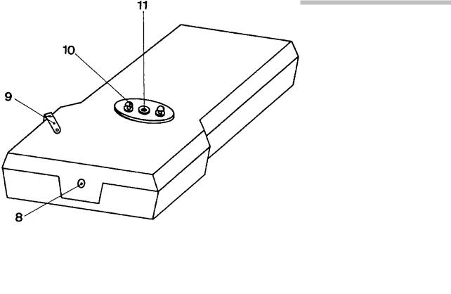
8) |
Tapped hole (1/4”) |
for rod to fit instrument onto a stand. |
9) |
Clamp |
the measuring system is locked when this lever is pushed in |
|
|
the direction of the arrow. |
10) |
Clamps |
for measuring cup (VT 01 only). |
11) Drive shaft for rotor |
When mounting a rotor, lock the measuring system with the |
|
|
|
clamp 9); attach the threaded coupling of the rotor to the |
|
|
drive shaft and switch on the drive motor. The coupling will |
|
|
be screwed in automatically. |
To remove the rotor, turn it in a clockwise direction (the threaded coupling has a left-handed thread).
5
 Loading...