

Page 1
9
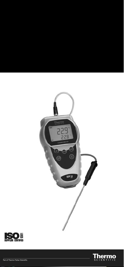
Instruction Manual
Precision RTD Thermometer
Temp-16
68X481903 Rev 0 03/0
Page 2

Page 3

TABLE OF CONTENTS
Quick
Start
Guide ....................................... 1
1. Introduction.......................................... 2
2. Safety Precautions............................... 3
3. Specifications ...................................... 4
4. Battery Installation And Replacement.. 6
5. Inserting And Removing Optional
Rubber Armour .................................... 7
6. Assembling Optional
Accesories
7.
Connecting
8. Key Functions...................................... 10
9. Display Overview................................. 11
10. Measurement Mode............................. 12
11. Selecting Temperature Scale .............. 13
12. Min And Max Function ........................ 14
13. Auto Off Function ................................ 14
14. Calibration ........................................... 15
15. Clear Field Calibration......................... 16
16. Field Calibration Unlock ...................... 16
17.
Field Calibration Lockout
18. Maintenance........................................ 18
19. Cleaning
20. Troubleshooting................................... 19
21. Service................................................. 20
22. Replacement Meter & Accessories...... 20
23. Warranty.............................................. 22
24. Product Return .................................... 22
25. Technical Assistance........................... 23
........................................... 8
An Rtd Probe .................... 9
............................................... 18
Handsfree
...................... 17
Page 4

Page 5

QUICK
START
GUIDE
To ensure best results please read the
complete manual.
1. Connect probe.
2. Press the on/off key.
Press again to turn on backlight.
3. Select °C or °F display using °C/°F key.
4. Insert probe in sample.
Allow adequate time for reading to
stabilize.
Response time will vary depending on
probe.
5. Take reading.
Press hold key to freeze display.
Press min/max to display minimum or
maximum temperature.
6. Press and hold the on/off key for three
seconds to turn meter off.
1
Page 6
1. INTRODUCTION
Thank you for choosing the
Temp-16 Precision RTD
Thermometer. This versatile
hand-held instrument
provides highly accurate
temperature measurements
and is designed for easy
operation which includes the
following features:
• Operator selection of Celsius or
Fahrenheit scale
• Resolution of 0.1° (auto ranging)
• Four-digit backlit LCD
• Hold feature to retain a reading
temporarily
• Field calibration capability
• Low battery warning
• Auto power off with Enable/Disable
function
• Min and max readings display
• 3-pin circular connector input
• Operates with a wide selection of
probes
2
Page 7

2. SAFETY PRECAUTIONS
W
G
Voltages present at the RTD may also be
present at the battery terminals. Always
disconnect the RTD when changing
batteries.
WARNIN
This instrument is designed to accept low
level signals supplied by standard 100 Ω
RTDs. Under no circumstances should the
input voltage exceed the specified 10 v rms.
1. Do not use or store this instrument in
microwave ovens or any abnormally hot
or cold areas.
2. Weak batteries should not be left in the
instrument. Dead batteries can leak and
cause damage to unit.
3
Page 8
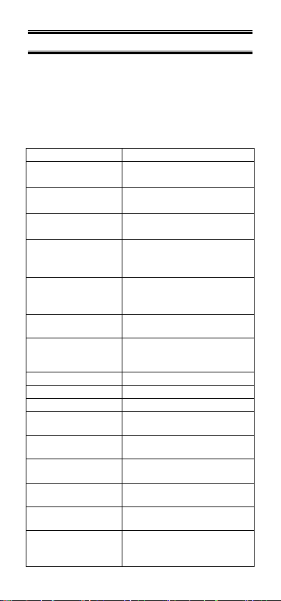
3. SPECIFICATIONS
Platinum RTD Probes
100 ohm platinum: alpha = 0.003850
–200 °C to 850 °C (–392 °F to 1562 °F)
Out of range display: “Ur”, “Or”, “OPEN”
Range Accuracy
–200.0 to –100.0 °C
(–392 to –148 °F)
–99.9 to 199.9 °C
(–148 to 392 °F)
200.0 to 850.0 °C
(392 to 1562 °F)
Resolution
Display
Display Update
Rate
Input
Input Protection
Battery
Battery Life
Auto Shutoff
Stated Accuracy
Useful Range
Storage
Humidity
Dimensions
Without armour
With armour
0.1° (–200.0 to 850.0 °C);
0.1° (–392.0 to 999.9 °F);
1° (1000 to 1562 °F)
4-digit LCD (¼ X ½" digits);
2
area
0.5 sec per update.
One probe with 3 pin
circular connector
(Switchcraft TA3F)
10V rms
Three AA, 1.5V alkaline
700 hours continuous
17 minutes after last
keypress.
18 to 28°C
(64 to 82°F)
0 to 40°C
(32 to 104°F)
-40 to 65°C
(-40 to 149°F)
10% to 90%
(non-condensing)
(L x W x H )
175 mm x 97 mm x 42 mm
180 mm x 102 mm x 52 mm
±2.0 °C
(±4.0 °F)
±0.2 °C
(±0.4 °F)
±2.0 °C
(±4.0 °F)
1
/3 X 1 ½" backlit viewing
4
Page 9

Weight
Without armour
With armour
Ingress Protection
(With Probe
Attached)
CE Compliance
267 g
362 g
Meets IEC-529 IP-54 for dust
and water-resistant
enclosures.
EN61326-1/A1:
1998 (EU EMC Directive)
5
Page 10

4. BATTERY INSTALLATION AND
REPLACEMENT
Voltages present at the RTD may also be
present at the battery terminals. Always
disconnect the RTD when changing
batteries.
Weak batteries should not be left in the
instrument. Dead batteries can leak and
cause damage to unit.
The typical battery life is about 700 hours.
Selected settings are stored in memory and
will remain in memory even after power
is turned off, or while batteries are being
replaced.
1. Before
2.
3.
4. Insert three
5.
changing
instrume
battery, tur
nt off
and disconnect probe
Loosen screw and
the
back
of case.
Remove
the t
hree
new
arity.
pol
Install
cover and
batteries
tighten
n
lift battery
AA batteries.
observing
screw
cover
.
.
off
6
Page 11

5. INSERTING AND REMOVING
OPTIONAL RUBBER ARMOUR
Figure 1: Removing Optional Rubber Armour
1. To insert thermometer into the optional
rubber armor, slide in from the top of
meter before pushing the bottom edges
of meter down to set it into position. Lift
up the stand at the back of meter for
bench top applications if necessary.
2. To remove thermometer from armor,
push out from the bottom edges of
meter until it is completely out of boot.
7
Page 12

6. ASSEMBLING OPTIONAL
HANDSFREE
ACCESORIES
You can use the optional magnets and strap
in the Hands Free Kit accessories for handsfree operations.
Figure 2: Hands Free Kit
8
Page 13

7.
CONNECTING
AN RTD PROBE
Use the correct 100 Ω RTD (alpha =
0.003850) for your instrument. Using an
incorrect probe type will result in erroneous
readings. Insert the 3-pin plug into the
mating connector on the top of the
instrument.
RTD Input
Figure 3: Top view of RTD Thermometer
9
Page 14

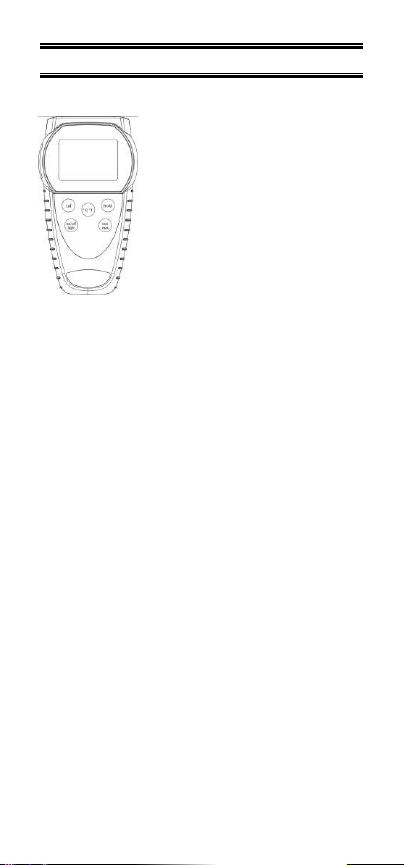
8. KEY FUNCTIONS
Figure 4: Keypad
Toggles between Celsius or
°C/°F
hold
max
on/off
light
Fahrenheit in measurement mode
and user calibration mode.
Press and hold this key for 3 seconds
cal
to enter Calibration mode if field
calibration is unprotected.
Activates/ Deactivates freezing of the
measured reading while in
measurement mode.
Toggles between minimum and
maximum readings (MIN and MAX
readings are calculated from the last
min
min/max keypress).
Press and hold this key for 3
seconds to clear the MIN/MAX
reading stored.
Powers on and shuts off the
thermometer by holding it for 3
seconds.
Press this key to activate/ deactivate
the backlight display. (Backlight will
automatically turns off within 30
seconds of activation).
10
Page 15

9. DISPLAY OVERVIEW
Figure 5: Meter Display
°C/°F Celsius or Fahrenheit indicator.
MIN Minimum reading annunciator.
MAX Maximum reading annunciator.
3 Bar : 700 – 550 hours
2 Bar : 350 – 550 hours
1 Bar : 150 – 350 hours
Blinking: < 150 hours
CAL
HOLD Remain in display during hold mode.
STABLE
Blinks during calibration mode.
Remains in display indicating field
calibration is active.
Displayed upon recognizing final
value.
11
Page 16

10. MEASUREMENT MODE
Press the on/off key. The thermometer
performs a self-test and all display digits and
indicators should remain on for
approximately two seconds before the meter
enters measurement mode.
If a probe is not connected or if the probe is
defective, the display will indicate “OPEN”.
°c
Figure 6: Display when no probe is detected
For optimum instrument accuracy, allow one
minute for ambient temperature stabilization.
If the unit has been stored at an extreme
ambient condition, more time will be needed.
A STABLE indicator appears at the top right
corner of the display when reading is
continuously stable for 5 seconds.
To freeze reading, press hold. Press hold
key again to release the reading and resume
normal operation.
HOLD STABLE
24.6
°c
Figure 7: HOLD and STABLE function
The display will show “Ur” (under range) or
“Or” (over range) if the temperature reading
is out of range of the instrument.
12
Page 17

11. SELECTING TEMPERATURE
SCALE
24.6
°C/°F
75.4
Figure 8: Press °C/°F key to toggle
between °C and °F
Select °C or °F by
h
time the
Eac
temperature
bet
ween °C and
during operatio
Each time
power up with
set when the unit was last
you
pressing
key is pressed,
scale will sw
°F
can be done
n.
turn the instrument on, it
the
same
°c
°F
the °C/°F
itch. Switc
settings that were
turned
off.
at
any
key
th
hing
time
e
will
.
13
Page 18

12. MIN AND MAX FUNCTION
Press the min/max key to toggle between
the minimum and maximum readings. The
minimum and maximum reading function is
ideal for monitoring unattended operations
while continually displaying every
temperature change that occurs. The
minimum and maximum values are sensed
and automatically stored. To exit and clear
the MIN/MAX reading stored, press and hold
the min/max key for 3 seconds.
13. AUTO OFF FUNCTION
The thermometer has a default auto off
function of 17 minutes.
To deactivate this function, press the
min/max key while turning the thermometer
on with the on/off key. “A.OFF no” flashes
to show indicate that the auto off function
has been disabled for that session.
A.off
Figure 9: Disabling the auto off function
14
Page 19

14. CALIBRATION
The CAL function allows single point
calibration of the thermometer at 0°C (32°F)
to compensate for probe offset error. Use
the field calibration feature to improve
thermometer/probe accuracy.
The Temp-16 Precision RTD Thermometer
comes with a calibration lock function to
prevent accidental changes to calibration
settings. A field calibration can only be
performed when the function has been
unlocked. To unlock field calibration, follow
steps 1 through 4 in FIELD CALIBRATION
UNLOCK section.
To calibrate:
1. Pack sensing end of probe in a
container tightly packed with crushed ice
and filled with distilled water. Allow
temperature to stabilize.
2. Press and release the cal key for 3
seconds to enter the calibration mode.
The CAL indicator starts blinking.
Release the cal key.
3. If the measured temperature is from
-5°C to 5°C (23 to 41°F) when the
temperature reading is stable, press the
cal key.
The CAL indicator will stop blinking, and the
reading will be set to 0°C (32°F). The CAL
indicator will remain in display, indicating
that field calibration is now active.
If “Err” is displayed, the displayed reading is
outside the above limits.
NOTE: Press any key (except the cal key)
while in calibration mode to abort
calibration.
15
Page 20

15. CLEAR FIELD CALIBRATION
To clear user calibration:
1. Turn the thermometer off.
2. Hold the cal key down while pressing
the on/off key.
3. The measurement mode window
appears without the CAL indicator to
indicate that the user calibration has
been successfully cleared.
16. FIELD CALIBRATION UNLOCK
The calibration unlock feature enables field
calibration operation. To unlock field
calibration:
1. Turn the thermometer off.
2. Hold the cal key and hold key down
simultaneously, then press the on/off
key.
3. The “CAL” indicator appears
momentarily with the version-model
window to indicate that the usercalibration function has been unlocked
successfully (Figure 10).
CAL
Rtd
Figure 10: Successful field calibration unlock
16
Page 21

4. When the cal and hold keys are
released, the unit will go to
measurement mode (Figure 11).
STABLE
°c
Figure 11: Unit goes to measurement mode
17.
FIELD CALIBRATION LOCKOUT
The calibration lockout feature prevents any
field calibration changes. The lockout
remains in effect until an unlock has been
performed. To lock the field calibration
operation:
1. Turn the thermometer off.
2. Hold the cal key and °C/°F key down
simultaneously, then press the on/off
key. Do not release cal and °C/°F keys
until the measurement mode is on
display.
3. If field calibration lockout is successful,
the version-model window appears
without the CAL indicator (Figure 12).
Rtd
Figure 12: Successful field calibration lockout
17
Page 22

4. When the cal and °C/°F keys are
released, the unit will return to
measurement mode (Figure 13).
STABLE
°c
Figure 13: Unit returns to measurement mode
18. MAINTENANCE
Properly used, the thermometer should
maintain calibration indefinitely and not
require service other than occasional
cleaning of the housing and changing of the
batteries. Do not clean with abrasives or
solvents. Use mild detergents; never
immerse nor use excessive fluid.
19. CLEANING
WARNING:
TO PREVENT IGNITION OF A
M
HAZARDOUS AT
LEC
TROSTATIC DISCHARGE, CLEAN
E
OSPHERE BY
WITH DAMP CLOTH.
Do
not
Use mild
clean wi
use excessive
th
abrasives or solven
detergents,
fluid.
never immerse nor
ts.
18
Page 23

20. TROUBLESHOOTING
Problem Cause Solution
Power on
but no
display
“OPEN”
display
on LCD
“Ur” or
“Or”
display
on LCD
Unstable
reading
Slow
response
Batteries not in
place or wrong
polarity.
Probe not
connected
Measurement
over (Or) or
Under (Ur) range
1. Probe not
deep enough
in sample
2. Broken probe
Dirty probe Clean probe
Insert batteries.
or re-insert
batteries in
correct polarity.
Make sure probe
is firmly
connected.
Ensure
temperature
taken is within
meter’s
specification.
1. Place probe
deeper in
sample.
2. Replace
probe.
19
Page 24

21. SERVICE
There are no internal adjustments or user
replaceable parts.
Note: Serial number label is located behind
the meter.
22. REPLACEMENT METER &
ACCESSORIES
Item
Temp-16 Thermistor TSTEMP16
Rubber Armour with Stand ARMORTEMP
Hands Free Kit (Two
Magnets and a Strap)
Thermo
Scientific
HNDSFRKIT
RTD Probes
ECPT56L
ECPT56C
ECPT56P
ECPT56A
RTD PT100 probe with
shaft length: 200 mm,
round-tip sensor tip: 3
mm diameter (for liquid
measurement); -50 to
+400 °C
RTD PT100 probe with
shaft length: 200 mm,
round-tip sensor tip: 5
mm diameter (for contact
measurement); -50 to
+400 °C
RTD PT100 probe with
shaft length: 500 mm,
penetration sharp sensor
tip: 4 mm diameter; ; -50
to +400 °C (for semisolid measurement)
RTD PT100 probe with
shaft length: 200 mm,
sensor tip: 4 mm
20
Page 25

ECPT56L 1/5 DIN
ECPT56 TFE
ECPT56/500
ECPT56/1000
ECTEM6TEM01R
diameter (for air
measurement); -50 to
+250 °C
RTD PT100 probe with
shaft length: 200 mm,
round-tip sensor tip: 3
mm diameter; -50 to
+400 °C
RTD PT100 probe with
shaft length: 100 mm,
round-tip sensor tip: 4
mm diameter; -50 to
+200 °C cable and probe
at 300 °C
RTD PT100 probe with
shaft length: 500 mm,
round-tip sensor tip: 6
mm diameter; -50 to
+400 °C
RTD PT100 probe with
shaft length: 1000 mm,
round-tip sensor tip: 6
mm diameter; -50 to
+400 °C
3 wire RTD Pt100
Temperature Probe
21
Page 26

23. WARRANTY
The Manufacturer warrants this product to
be free from significant deviations from
published specifications for a period of three
years. If repair or adjustment is necessary
within the warranty period, the problem will
be corrected at no charge if it is not due to
misuse or abuse on your part as determined
by the Manufacturer. Repair costs outside
the warranty period, or those resulting from
product misuse or abuse, may be invoiced
to you.
24. PRODUCT RETURN
To limit charges and delays, contact the
seller or Manufacturer for authorization and
shipping instructions before returning the
product, either within or outside of the
warranty period. When returning the
product, please state the reason for the
return. For your protection, pack the product
carefully and insure it against possible
damage or loss. Any damages resulting
from improper packaging are your
responsibility.
22
Page 27

25. TECHNICAL ASSISTANCE
If
you have any questions abo
prod
of this
or authorized se
uct, contact the
ller.
ut the
use
Manufacturer
For more information on Thermo Scientific
Products, please contact your nearest
distributor or visit our web site listed
below:
Thermo Scientific
Water Analysis Instruments
Blk 55 Ayer Rajah Crescent
#04-16 Singapore 139949
Tel: (65) 6778 6876
Fax: (65) 6773 0836
Website:
Email:
www.thermo.com
wai.asia@thermofisher.com
/water
23
Page 28

Distributed by
:
 Loading...