

Page 1
U
68X343601 Rev 1 05/07
SER GUIDE
RS-232C Adapter
(Model 91100-85)
Page 2

CONTENTS
Before You Begin… …………………………………1
Devices that can be used with this RS232 Adapter……1
What this adapter enables you to do…………………..1
What you need before using the adapter……………...1
Connecting Your RS232C Adapter………………….2
Setting Up Your Devices……………………………..3
Setting Up Your Thermo Devices…………………..4
91100-50 DuaLogR Set-Up…………………………….4
93210-50 and 93410-50 ThermoLogR Set-Up………......4
37003-02 HumidityLogR Set-Up………………………5
Transferring Live Readings……………………………...5
Transferring Stored Readings………………………….5
WINDOWS XP
HYPERTERMINAL Set-Up……………………………5
Port Settings for all other models…………..............6
Troubleshooting………………………………….…6
Accessories………………………………………..…7
Page 3
BEFORE YOU BEGIN…
Devices that can be used with this RS232 Adapter:
91100-50 DuaLogR Thermocouple Thermometer
93210-50 ThermoLogR Thermister Thermometer
93410-50 ThermoLogR RTD Thermometer
37003-02 HumidityLogR Thermohygrometer
pH/ ORP/ Ion/ Conductivity/ TDS/ Salinity/ Resistivity/ Dissolved
Oxygen Handheld Meters:
PCD 650
PC 650 & PD 650
CD 650
pH 620, 610 & 600
COND 610, 600 & DO 600
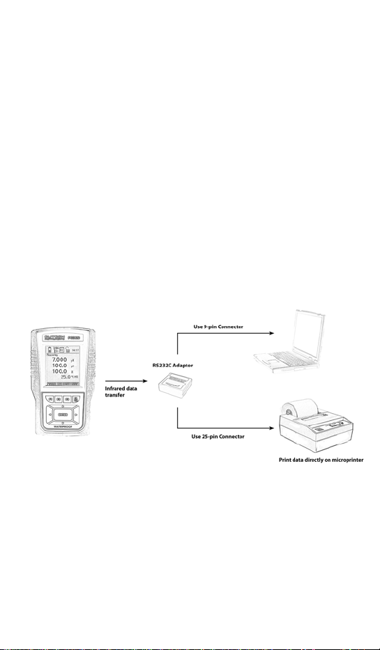
What this adapter enables you to do:
The RS232 Adapter receives your data via Infrared signals and lets you print
directly through a PC or a microprinter.
What you need before using the adapter:
• Your computer must have a serial communications port that can
be set at 300, 600,1200, 2400 baud.
• Your computer must have Windows Terminal, Windows
Hyperterminal or other compatible RS232 programs. However, it
is NOT compatible with the Cybercomm software.
1
Page 4

CONNECTING YOUR RS232C ADAPTER
If you are connecting to a Laptop or computer, please use the 9-pin plug.
1) Connect the phone jack cable to your RS232C adapter and the
NOTE: There is no need for a separate power supply for the RS232Cadapter
as it will be automatically powered by the PC or the microprinter’s main
power supply once you connect them.
other end to the 9-pin connector plug or 25-pin connector plug.
2) If using a PC, ensure that your PC is plugged into a power source
or has sufficient battery power.
3) If using the microprinter, plug in the power supply adapter to a
power source and connect the cable to the microprinter.
*Important: Please ensure that the RS232 adaptor shows a
red light.
2
Page 5

SETTING UP YOUR DEVICES
For 600 series devices:
PCD 650, PC 650 & PD 650
CD 650, pH 620, 610 & 600
COND 610, 600 & DO 600
In order to start printing on your Microprinter, you must first configure your
device to be compatible with it. Please follow these steps:
1) Turn your device on.
2) With the e or f arrows, shift the bar till you see SETP on the
screen and select it using the corresponding “F” button.
3) Then press ENTER to proceed.
4) You will see the word SYSTEM. Press ENTER again to select it.
5) Using the correct “F” button, select NEXT-P three times until you
reach SYSTEM –PAGE 4.
6) At this page, select PRINT MODE and change IrDA to LED by
using the c or darrows.
7) Then hit ENTER to move one step down to DATA FORMAT.
8) If you’re printing on a PC with the Hyperterminal* software or on
the microprinter, change the format to TEXT using the c or d
arrows.
9) Hit F4 to exit.
10) Face the device’s infrared window (usually on the left side of
device) directly to the RS232 Adapter’s infrared window. *Do Not
Move These Positions During Printing.
11) To print, simply use the e or f arrows to scroll until you see
PRIN.
12) Turn on your microprinter and select PRIN using the correct “F”
NOTE: Before printing, please refer to manual for microprinter to configure
it with a BAUD rate of 2400 BAUD, 8 data bits, parity = none, stop bits =1.
*This adapter only works on Hyperterminal and NOT Cybercomm software.
button.
3
Page 6

SETTING UP YOUR THERMO DEVICES
For these devices: 91100-50 DuaLogR Thermocouple Thermometer
91100-50 DuaLogR Set-Up
The interval may be set to any time from once every 3 seconds to once
every hour. This example will set the thermometer to print live readings
once every 3 seconds.
1. Press SETUP, then PRINT. The display indicates
“minutes:seconds” with the last printing interval setup shown.
The seconds will be flashing.
2. Press MAX (up) or MIN (down), until the flashing digits indicate
“03” seconds.
3. Press HOLD (enter). The display will show the minutes flashing.
4. Press HOLD again. The large upper display will show “HP”, “300”
or “600”.
5. Press MAX until “600” shows (use “300” for HYPERTERMINAL) in
the upper display.
6. Press SETUP to exit.
Aim the top of the unit at the red window of the adapter at a distance of 12
inches or less.
93210-50 and 93410-50 ThermoLogR Set-Up
The interval may be set to any time from once every 3 seconds to once
every hour. This example will set the thermometer to print live readings
once every 3 seconds.
1. Press SETUP, then PRINT. The display indicates
“minutes:seconds” with the
2. last printing interval setup shown. The seconds will be flashing.
3. Press MAX (up) or MIN (down), until the flashing digits indicate
“03” seconds.
4. Press HOLD (enter). The display will show the minutes flashing.
5. Press HOLD again. The large upper display will show “HP”, “300”,
“600”, “1200” or “2400”.
6. Press MAX until “2400” shows in the upper display.
7. Press SETUP to exit.
Aim the top of the unit at the red window of the adapter at a distance of 12
inches or less.
93210-50 ThermoLogR Thermister Thermometer
93410-50 ThermoLogR RTD Thermometer
37003-02 HumidityLogR Thermohygrometer
4
Page 7

37003-02 HumidityLogR Set-Up
The interval may be set to any time from once every 4 seconds to once
every hour.
This example will set the thermohygrometer to print live readings once
every 4 seconds.
Press SETUP, then PRINT. The display indicates “minutes:seconds” with the
last printing interval setup shown. The seconds will be flashing.
1. Press MAX (up) or MIN (down), until the flashing digits indicate
“04” seconds.
2. Press HOLD (enter). The display will show the minutes flashing.
3. Press HOLD again. The large upper display will show “HP”, “300”,
“600”, “1200” or “2400”.
4. Press MAX until “2400” shows in the upper display.
5. Press SETUP to exit.
Aim the top of the unit at the red window of the adapter at a distance of 12
inches or less.
Transferring Live Readings
To begin data transfer, press PRINT. Whenever the “PRINT” annunciator is
displayed on the unit, and the red light inside the RS-232 adapter is blinking,
data should appear on your computer screen.
Transferring Stored Readings
The “STO” annunciator on the unit’s display indicates that readings are
stored in memory. Press RECALL then PRINT to begin data transfer. “RCL”
and “PRINT” annunciators will be on the thermometer display, and the
number of readings remaining to be transferred will count down. The red
light inside the RS232 adapter should be blinking.
WINDOWS XP Hyperterminal Set-up
1. Click on Accessories, select Communications, then Hyperterminal.
2. Under NAME: Enter a name for your file and click on OK.
3. Under CONNECT USING: Choose COM1.
3. Click on OK.
4. Under COM1 PROPERTIES: Enter 2400, hit Tab, 8, hit Tab, None, hit Tab,
and 1.
5. Click on OK.
6. Check that the red light inside the window of the adapter is on.
7. Align the infrared windows and select PRIN.
5
Page 8

Port Settings for all other models:
Baud Rate Data Bits Parity Flow Control Stop Bits 2400 8 None None 1
1) Click on OK. A red light should now be visible in the window of the RS-
232C adapter.
2) To transfer the data, click on “Transfer”. Then “Capture Text”.
3) Enter a descriptive file name and click OK.
4) Press PRINT on the DuaLogR (see below). When all of the data has
transferred click on “Transfer”, “Capture Text”, then “Stop”.
The next time you run HYPERTERMINAL, you may select DuaLogR.ht. The
HYPERTERMINAL program will automatically be configured as above. Then,
if the “Connection Description” window pops up, just click on “Cancel”.
TROUBLESHOOTING
When incorrect or random characters appear on your screen, move the
adaptor away or shield it from other types of light sources such as
fluorescent lighting, as they may interfere with the data transfer.
6
Page 9

ACCESSORIES
Order Code Part No. Description
01X344202 01X344202 RS232 (LED) Interface Adaptor
ECMICROPRNTR01 01X230001 Serial Impact Microprinter (110
ECMICROPRNTR02 01X230002 Serial Impact Microprinter (220
ECMICROPRNTRO2CLK 01X230004 Serial Impact Microprinter with
ECMICROPRNTRO1CLK 01X230005 Serial Impact Microprinter
(for Meter to PC/Microprinter
Communication)
VAC)
VAC)
Real Time Clock (220 VAC)
(110/120 VAC) power adapter
7
 Loading...