

Page 1
Instruction Manual
Alpha Link 600
Data Acquisition Software for
Alpha 600 Series
68X450202 | Rev.0 | Oct 2008
Page 2

Page 3

Preface
This manual serves to explain the use of the Alpha 600 Link Data Acquisition
Software (DAS). The manual functions in two ways, firstly as a step-by-step guide to
help the user work with software application. Secondly, it serves as a handy reference
guide. It assumes that the user is familiar with setting up, calibrating & measuring with
the Alpha 600 series RF Transmitters. If there are doubts in the use of this software,
please do not hesitate to contact the nearest Authorized Distributor.
The information presented in this manual is subject to change without notice as
improvements are made, and does not represent a commitment on the part of Thermo
Scientific.
Thermo Scientific cannot accept any responsibility for damage or malfunction of the unit
due to improper use of the instrument.
Copyright © 2008
All rights reserved
Page 4

Page 5

TABLE OF CONTENTS
1 GETTING STARTED 1
1.1 Overview ········································································································1
1.2 Installing the Alpha Link 600 ·········································································· 2
1.3 Conn
ecting the Alpha 600 Transmitters to the Alpha Link 600 Program ······7
2 CUSTOMIZING YOUR PANEL VIEWS 8
2.1 The Alpha Link 600 Interface ········································································· 8
2.2 The Reading View Panel (Main Panel)··························································9
2.3 The Instrument View
Panel (Left Panel) ························································ 11
3 VIEWING & GENERATING REPORTS 12
3.1 Viewing Reports ····························································································· 12
3.2 Report Formats ······························································································13
4 ORDER INFORMATION 15
4.1 Thermo Scientific Instruments ······································································· 15
4.2 Eutech Instruments ························································································16
5 GENERAL INFORMATION 17
5.1 Warranty········································································································· 17
5.2 Return of Goods·····························································································17
Page 6

Page 7
1 GETTING STARTED
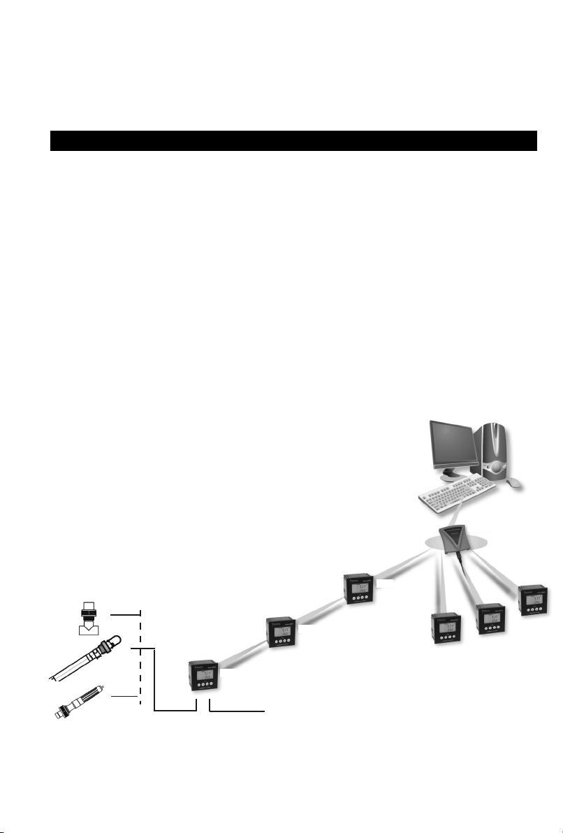
1.1 Overview
Alpha Link 600 is a Windows
®
based add-on application software to the Alpha 600
Transmitter series. This software allows you to monitor water quality parameters at up to
10 locations from the comfort of your desktop, round the clock and uninterrupted, so you
can detect and react to malfunctions faster.
Key features of CyberComm:
• 24/7 real-time data transfer from up to 10 meters, wirelessly and
simultaneously, to your computer
• Data-logging with time, date, temperature and locations
• Allows report generation of logged data in the form of raw
information, pie-chart and run-chart format
• Logs down each time a reading falls outside set range for future
system troubleshooting and analysis
Housing and
Sensors
Measurement
Cable
50m
50m
Power Adaptor
(9 V DC)
1
100m
100m
Wireless
100m
100m
Page 8
1.2 Installing the Alpha Link 600
System Requirements:
• Microsoft
®
Windows 2000, XP or Vista
• 1024 x 768 minimum screen resolution. A resolution of 1280 x
1024 is recommended.
• Recommended system memory 500 MB
• USB communication port
To install the Alpha Link 600 Program:
Note
Administrator rights are required to install this programme in your computer.
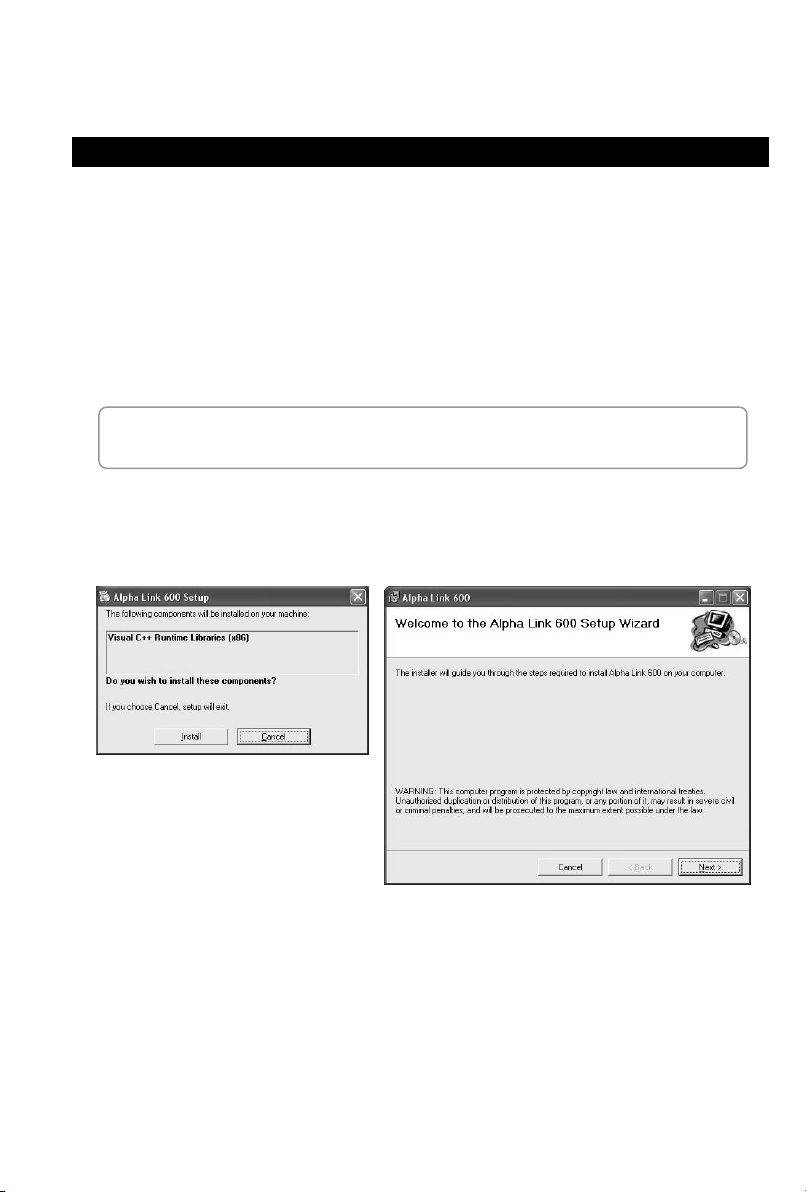
1. Insert the Alpha Link 600 installation CD into the CDROM drive of your PC. The
installation wizard should start running automatically (Figure 1).
Figure 1: Preparing to install
2. Click Install, followed by Next to continue.
2
Page 9
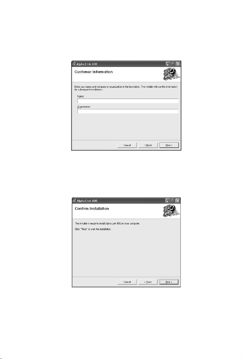
3. The next screen (Figure 2) gives you the option of entering your name & your
organization’s name, or leaving them blank. Click Next to continue.
Figure 2 : Customer information
4. By default, the program will be installed in the following directory: ‘C:/Program Files/
Thermo /Alpha Link 600’. Click “Next” to begin installing the program in this folder.
Click “Cancel” to stop installing and exit the installation wizard (Figure 3).
Figure 3 : Confirm installation
3
Page 10

5. The following screen is displayed upon successful installation of the program
(Figure 4). Click Close to exit the wizard. Do not remove the installation CD from
your CDROM drive.
Figure 4 : Installation completed
6. Connect the transceiver to your computer. The Found New Hardware Wizard
launches automatically upon detecting the transceiver to prompt for USB driver
installation. This is a one-time installation. Select “Yes, this time only”, then click
“Next” to proceed. (Figure 5).
Figure 5 : Found New Hardware Wizard
4
Page 11

7. The next screen prompts you to point the Wizard to the location of the USB driver.
This driver can be located in the Alpha Link 600 installation CD. Select “Install from
a list or specific location” (Figure 6). Click “Next” to proceed.
Figure 6 : Select “Install from a list or specific location”
8. Select “Search for the best driver in these locations”, follow by “Include this location
in the search” to narrow the search locations. Click “Browse” and select the folder
“USB Driver” in the CD (Figure 7). Click “Next” to proceed.
Figure 7 : Select “USB Driver” from the Alpha Link 600 Installation CD
5
Page 12

9. The Wizard proceeds to search and install the USB driver (Figure 8).
Figure 8 : The Wizard procceds to search and install the USB driver
10. The following screens are displayed upon successful installation of the USB driver
(Figure 9). Click Finish to exit the wizard.
Figure 9 : Installation complete
11. Locate the “Alpha Link 600” shortcut icon on your Desktop.
Launch the Alpha Link 600 program by double-clicking on the
icon. Your Alpha Link 600 is now ready to communicate with your
Alpha 600 series transmitters.
Note
To locate the program if the shortcut icon does not appear on
your desktop, go to: C:\Program Files\Thermo Fisher
Scientific\Alpha Link 600\Thermo Fisher Scientific
6
Page 13

1.3 Connecting the Alpha 600 Transmitters to the Alpha Link 600 Program
1.3.1 Instrument ID
Each Alpha 600 transmitter carries a unique instrument ID. This instrument ID is the
same as the serial number of the instrument, and must be registered on the Alpha Link
600 for the program to start transmitting and reading data from the transmitter. The
instrument ID of each transmitter is factory-assigned and cannot be changed or reassigned by the user. This is important in maintaining communication between the
transmitter and the host PC, and in ensuring data integrity of various instrument
transmitting at same time.
The transceiver is designed to ignore all other transmission signals except for those that
are from the registered transmitters, even if there are other transmitters within the
transceiver range. To check if your transmitter is registered on the software, select
Instrument ID > View Registered Instrument from the main menu. This will show you
a list of transmitters registered on the program.
1.3.2 Registering Your Alpha 600 Transmitter
Each trans
ceiver allows you to register up to 10 transmitters. The registration information
is stored within the transceiver, so the transceiver continues to detect the registered
transmitters no matter which computer the transceiver is connected to. To register your
Alpha 600 Transmitter on the Alpha Link 600 program:
1. Select Instrument ID > Register New
Instrument from the main menu.
2. Locate the six-digit numeric instrument
ID at the bottom of your Alpha 600
Transmitter
3. Type the instrument ID in the dialog box
(Figure 10) and select OK.
Figure 10 : Instrument ID Dialog
Note
The Alpha Link 600 will only be able to read transmitted data from your Alpha
600 transmitters after successful installation of the USB driver.
7
Page 14

2 CUSTOMIZING YOUR PANEL VIEWS
2.1 The Alpha Link 600 Interface
Figure 11 : Alpha Link 600 Interface
The Alpha Link 600 has two main view panels: The Reading View Panel (Main Panel), and the Instruments View Panel (Left Panel).
8
Page 15

2.2 The Reading View Panel (Main Panel)
your captio
The main panel of Alpha Link 600 comes with four view windows, V1, V2, V3 and V4
(Figure 12), allowing you to monitor 4 transmitters simultaneously, or one transmitter in
three different views.
2. Caption. Doubleclick on this to input
3. Measurement Mode
n.
1. Unique Instrument ID
4. Current Reading
5. Temperature
Reading
1. Data Reading View
Parameter, current reading,
temperature reading and ATC/MTC
setting.
6. Status of Transmission
Figure 12 : View Window
9
Page 16

2. Alarm Logging View
Log of alarms when measurements fall
below or exceed set limits.
3. Graph View
Line graph to exhibit measurement
trend over time.
To select the view you want:
1. Click on a view window. A pop-up menu will appear (Figure 13).
2. Select “Data”, “Alarm” or “Graph” according to the view you want.
Figure 13 : View Window Pop-Up Menu
10
Page 17

2.3 The Instrument View Panel (Left Panel)
The Instrument View Panel on the left of the screen displays all connected transmitters
within range, each represented by their unique ID number. A pop-up menu appears
when you click on a transmitter icon (Figure 14).
3. Unique Instrument ID
4. Caption. This can
only be customised in
the Reading View Panel
(Main Panel)
4. Status of transmission
Figure 14 : Transmitter icon in the Instrument View Panel
1. Setup Button for
customisation of
transmitter settings
2. To view the data of
a transmitter, simply
click on the Transmitter
icon and check V1, V2,
V3 and/or V4 to display
its data in the Reading
View Panels
Setup Button
The set-up button allows you to customise the data logging, high/low limit alarm and
graphical logging set up for each transmitter.
Figure 15 : Set-up Menu
11
Page 18

3 VIEWING & GENERATING REPORTS
3.1 Viewing Reports
The Alpha Link 600 saves and presents data according to user-assigned captions under
each meter.
To view report:
1. Select Report > View Report in the main menu. A dialog window will appear
(Figure 16)
2. Select the Instrument ID in the drop down box
3. Select the Measurement Mode.
4. Once the Instrument ID and Measurement Mode have been selected, a list of
available reports will appear. Double-click on a report to view it.
Figure 16 : Select Report
5. A report dialog window will appear, giving you four format options to view your
data.
12
Page 19

3.2 Report Formats
Users can choose to view data reports in four different formats:
3.2.1 Raw Data
Measurements
with date, time and temperature.
Figure 17 : Raw Data Report
3.2.2 Alarm Log
Log of measurements which fell outside set limits.
Figure 18 : Alarm Log
13
Page 20

3.2.3 Graph Report
Data displayed in line graph format to show fluctuation patterns. Hover mouse over a
node to see the measurement value, time and date of the data.
Figure 19 : Graph Report
3.2.4 Pie Chart Report
Data displayed in pie-chart format to show percentage of readings in each range, up to
0.1 intervals.
Figure 20 : Pie Chart Report
14
Page 21

4 ORDER INFORMATION
4.1 Thermo Scientific Instruments
pH Monitor Replacement and Accessories
Item Description
Alpha pH 600 wall-mount pH/ORP RF transmitter TSPHCTP0600
Wireless (RF) receiver with application software TSRCV0600S
Ryton®-body pH combi electrode with Pt100 RTD (ATC) & 20 m cable with BNC &
PMP
Ryton®-body pH combi electrode with Pt100 RTD (ATC) & 10 m cable with BNC &
PMP
Ryton®-body pH combi electrode with Pt100 RTD (ATC) & 5 m cable with BNC &
PMP
Ryton®-body pH combi electrode with 5 m cable with BNC & connector for PMP
(no ATC)
Ryton®-body pH combi electrode with 5 m cable with BNC connector (no ATC);
measures up to 110 ºC
Ryton®-body pH combi electrode without ATC & 5 m cable with BNC connector.
HF resistant glass
Ryton®-body pH combi electrode with 5 m cable with BNC connector (no ATC) ECARTSO05B
Ryton®-body ORP gold electrode with 5 m cable with BNC & PMP (no ATC) ECHTAUTSO05B
Ryton®-body ORP platinum electrode with 5 m cable with BNC & PMP (no ATC) ECHTPTTSO05B
Order Code
EC100GTSO20B
EC100GTSO10B
EC100GTSO05B
ECARGTSO05B
ECARHTTSO05B
ECARTSOHF05B
Calibration Solutions
Item Description
pH 4.01 buffer solution, 480 ml bottle EC-BU-4BT
pH 7.00 buffer solution, 480 ml bottle EC-BU-7BT
pH 10.01 buffer solution, 480 ml bottle EC-BU-10BT
pH 4.01 buffer sachets, 20 ml x 20 pcs. EC-BU-4BS
pH 7.00 buffer sachets, 20 ml x 20 pcs. EC-BU-7BS
pH 10.01 buffer sachets, 20 ml x 20 pcs. EC-BU-10BS
pH De-ionized water rinse sachets, 20 ml x 20 pcs EC-RIN-WT
pH sachet assortment pack – 5 each of pH 4.01, pH 7.00, pH 10.01 and de-ionized
water sachets per box
Protein cleaning solution for pH electrode EC-DPC-BT
Storage solution for pH electrode EC-RE-005
Order Code
EC-AST-PK
NOTE:
• pH buffer solutions (480 ml bottle) have ±0.01 pH accuracy at 25 °C
• pH buffer sachets are individually sealed, single use pouch containing
20 ml of fresh, contamination free calibration solution
• pH buffer sachets have ±0.01 pH accuracy at 25°C
15
Page 22

4.2 Eutech Instruments
pH Monitor Replacement and Accessories
Item Description
Alpha pH 600 transmitter 56706-00
Wireless RF receiver with application software 56706-50
pH/Temp electrode with PMPO and 10-ft cable 35807-20
Platinium ORP electrode with 10-ft cable 35801-21
BNC to spade lug adapter 05994-90
Order Code
Calibration Solutions
Item Description
pH 4.01 calibration buffer, 500 ml 00654-00
pH 7.01 calibration buffer, 500 ml 00654-04
pH 10.01 calibration buffer, 500 ml 00654-08
pH 4.01 calibration buffer solution pouches, 20/box 35653-01
pH 7.00 calibration buffer solution pouches, 20/box 35653-02
pH 10.00 calibration buffer solution pouches, 20/box 35653-03
pH De-ionized water rinse sachets, 20 ml x 20 pcs 35653-00
Assortment pack – 5 each of pH 4.01, pH 7.00 and pH 10.00 solution pouches. 35653-04
Electrode cleaning solution 00653-06
Electrode storage solution 00653-04
Order Code
NOTE: To order Eutech accessories, contact the nearest Oakton distributor
16
Page 23

5 GENERAL INFORMATION
5.1 Warranty
This transmitter is supplied with a one-year warranty against significant deviations in
material and workmanship from date of purchase and a six-month warranty for probe.
Each instrument will have a warranty card with a specific serial number. The warranty
card must be endorsed by the Authorized Distributor at the point of sale.
If repair or adjustment is necessary and has not been the result of abuse or misuse
within the designated period, please return – freight pre-paid – and correction will be
made without charge. Thermo Scientific/ Eutech will determine if the product problem is
due to deviations or customer misuse.
Out of warranty products will be repaired on a charged basis.
Exclusions
The warranty on your instrument shall not apply to defects resulting from:
• Improper or inadequate maintenance by customer
• Unauthorized modification or misuse
• Operation outside of the environment specifications of the products
5.2 Return of Goods
Authorization must be obtained from our Customer Service Department or authorized
distributor before returning items for any reason. A “Return Goods Authorization” (RGA)
form is available through our authorized distributor. Please include data regarding the
reason the items are to be returned. For your protection, items must be carefully packed
to prevent damage in shipment and insured against possible damage or loss. Thermo
Scientific will not be responsible for damage resulting from careless or insufficient
packing. A restocking charge will be made on all unauthorized returns.
NOTE: Thermo Scientific reserves the right to make improvements in design,
construction, and appearance of products without notice.
17
Page 24

Page 25

Page 26

Page 27

Page 28

Thermo Scientific
Water Analysis Instruments
North America 166 Cummings Center
Europe
Asia Pacific
Beverly, MA 01915 USA
Toll Free: 1-800-225-1480
Tel: 1-978-232-6000
Dom. Fax: 1-978-232-6015
Int’l Fax: 978-232-6031
www.thermo.com/process
Denmark House, Angel Drove
Ely, Cambridgeshire
CB7 4ET, UK
Tel: 44-1353-666111
Fax: 44-1353-666001
Blk 55, Ayer Rajah Crescent,
#04-16/24 Singapore 139949
Tel: (65) 6778 6876
Fax: (65) 6773 0836
E-mail: eutech@thermofisher.com
Oakton Instruments
P.O Box 5136,
Vernon Hills, IL 60061, USA
Tel (in U.S.): 888-462-5866
Tel (outside U.S.): 1-847-549-7600
Fax: (1) 847-247-2984
E-mail: info@4oakton.com
Web-site: http://
www.4oakton.com
Distributed by:
 Loading...