


HyPerforma 2:1 Single-Use
Bioreactor (S.U.B.) User’s Guide
DOC0014 • Revision H
January 2021

Contents
Warnings, safety, and warranty information 1
How to use this guide 7
Chapter 1 HyPerforma 2:1 Single‑Use Bioreactor overview 12
1.1 Introduction to the Single-Use Bioreactor 13
1.2 Hardware characteristics 15
1.2.1 S.U.B. hardware components 15
1.2.2 S.U.B. system features 17
1.2.3 Additional system components 18
1.3 End user and third-party supplied components 25
1.3.1 pH and DO probes 25
1.3.2 Controllers 26
1.4 BPC features 27
Chapter 2 Hardware assembly and setup 30
2.1 Initial installation preparation 31
2.1.1 Hardware shipment and setup 31
2.1.2 Hardware uncrating 31
2.1.3 Site preparation 31
2.2 Installation and setup 33
2.2.1 Preparing load cells 33
2.2.2 Leveling and connecting the system 35
2.2.3 Attaching the cable management system arm 37
Chapter 3 Operating information 38
3.1 General system operating information 39
3.1.1 BPC preparation 39
3.1.2 BPC handling instructions 39
3.1.3 BPC operating information 39
3.1.4 Hardware operating information 41
3.1.5 External data logging and control 44
3.2 BPC and drive shaft loading instructions for 50, 100,
and 250 L systems 44
3.2.1 Initial BPC loading steps for 50, 100, and 250 L
systems 44

Contents
3.2.2 Drive shaft insertion for 50, 100, and 250 L
systems 49
3.2.3 Final installation steps for 50, 100, and
250 L systems 53
3.3 BPC and drive shaft loading instructions for 500
and 1,000 L systems 55
3.3.1 Initial BPC loading steps for 500 and 1,000 L
systems 55
3.3.2 Drive shaft insertion for 500 and 1,000 L systems 61
3.3.3 Final installation steps for 500 and 1,000 L
systems 66
3.4 BPC and drive shaft loading, and condenser system
setup instructions for 2,000 L systems 69
3.4.1 Initial BPC loading steps for 2,000 L systems 69
3.4.2 Condenser system setup for 2,000 L systems 78
3.4.3 Drive shaft insertion for 2,000 L systems 89
3.4.4 Final installation steps for 2,000 L systems 95
3.5 Probe preparation and insertion 98
3.5.1 Preparation and sterilization 98
3.5.2 Making Kleenpak connections 99
3.5.3 Probe insertion 108
3.5.4 Probe calibration 109
3.6 Cell culture operating instructions 110
3.6.1 Operating conditions for cell culture applications 110
3.6.2 Checkpoints prior to media fill 111
3.6.3 Media fill 111
3.6.4 Agitation for units with E-Boxes 112
3.6.5 Agitation rate calculations 113
3.6.6 Drive shaft rotation 117
3.6.7 Temperature control 118
3.6.8 Sparging strategy 119
3.6.9 pH probe calibration 123
3.6.10 DO probe calibration 123
3.6.11 Checkpoints prior to inoculation 124
3.6.12 Cell inoculation 124
3.6.13 Volume scale up 124
3.6.14 In-process checkpoints 125

Contents
3.6.15 BPC sampling 125
3.6.16 Dispense and harvest 128
3.6.17 BPC disposal 128
3.6.18 S.U.B. shutdown 129
3.6.19 Preparation for the next run 129
3.7 Verification procedures 129
3.7.1 Mixing speed verification 129
3.7.2 Temperature controller verification 130
3.7.3 Pressure monitor verification (when present) 130
3.7.4 Load cell verification 130
Chapter 4 System features and specifications 131
4.1 Hardware features 132
4.1.1 Design features for 50–250 L systems 132
4.1.2 Design features for 500–1,000 L systems 133
4.1.3 Design features for 2,000 L systems 134
4.2 Hardware specifications 135
4.3 E-Box features 153
4.4 BPC specifications 154
4.5 Additional system component part numbers 175
Chapter 5 Maintenance and troubleshooting 179
5.1 Maintenance 180
5.1.1 Routine maintenance 180
5.1.2 Preventive maintenance 180
5.2 Troubleshooting and frequently asked questions 182
5.2.1 Hardware operation issues 182
5.2.2 Cell culture operation issues 185
5.2.3 Sparging issues 186
5.2.4 Probe and connector issues 187
5.2.5 Other issues 188
Chapter 6 General ordering information 190
6.1 Ordering instructions 191
6.2 Ordering/support contact information 191
6.3 Technical support 192

Contents
Appendices Appendix A—Installation of female electrical receptacle
for units with AC motors and electrical boxes 193
Appendix B—Mettler Toledo IND331 display load cell
calibration instructions 196
Appendix C—2,000 L S.U.B. agitator operation and
maintenance guidelines 198
Appendix D—Drive shaft use log 199

Warnings, safety, and warranty information
Warnings, safety, and warranty
information
Thank you for purchasing this high-quality Thermo Scientific
equipment. We have included safety information in this guide, based
on our knowledge and experience. It is important, however, for you
to work with your Safety Management personnel to ensure that this
equipment is integrated into your safety practices. Please take some
time to perform your own job safety analysis in order to identify and
control each potential hazard.
WARNING: Read and understand this user's guide before
operating the equipment.
The Thermo Scientific
is designed to be operated under traditional eukaryotic cell culture
conditions. A general understanding of bioreactor systems and their
operation is important prior to using the system for the first time. Read
and understand the user’s guide before operating; failure to do so
could result in injury and potential loss of product.
™
HyPerforma™ Single-Use Bioreactor (S.U.B.)
WARNING: Hazardous voltage inside.
The mixer motor, motor controller and control panel all have
electrical components. There is a risk of electrical shock and
injury. Disconnect power before opening electrical components.
Service should be performed by Thermo Fisher Scientific service
personnel only. Thermo Fisher Scientific recommends using standard
lockout procedures when working on electrical components. The main
breaker on the electrical box may be locked out.
WARNING: Static electricity may build up in BPCs.
• BioProcess Containers (BPCs) may act as insulators for
electrostatic charge. If electrostatic charge is transferred to a BPC,
the charge may be stored in the BPC and/or the product inside.
This phenomena varies by product and use; therefore, it is the sole
responsibility of the end user to ensure a hazard assessment is
conducted and the risk of electrostatic shock is eliminated.
• Where applicable, a product contact stainless steel coupler may be
grounded to the frame to dissipate electrostatic build up from the
material within a BPC. It is good practice to dissipate electrostatic
buildup by grounding all BPCs prior to coming in contact with them.
When working with BPCs, the use of non-conductive materials,
such as non-conductive gloves, is recommended.
HyPerforma 2:1 Single‑Use Bioreactor User's Guide | 1Thermo Scientific

Warnings, safety, and warranty information
WARNING: Rotating parts—entanglement hazard.
Rotating and moving parts can cause injury. Keep hands away from
moving parts during operation.
• Do not operate this equipment unless the supplied guarding is in
place and properly functioning.
• It is the responsibility of the end user to assess this equipment
and ensure that equipment and safeguards are in good working
condition, and that all operators are trained and aware of
entanglement hazards and associated protective devices, such as
hazard signs and guarding.
WARNING: Use ladders and elevated platforms with caution.
A few operations, such as loading a BPC into a large S.U.B., may
require the use of a ladder or platform. Before use, ensure the ladder
has been inspected and weight-rated for its user. When using a ladder
or platform, be sure it is stable, maintain three points of contact, and
make sure the steps are clean.
WARNING: Follow lockout/tagout procedures.
To prevent injury, when servicing equipment, use your company's
lockout/tagout procedures to isolate electrical, mechanical, pneumatic,
hydraulic, chemical, thermal, gravitational, or any other potential energy
and protect workers from the release of hazardous energy.
WARNING: Use caution with hazardous chemicals or materials.
Personnel servicing equipment need to know the hazards of any
chemicals or materials that may be present on or in the equipment.
Use general hazard communication techniques such as Safety Data
Sheets, labels, and pictograms to communicate any hazards.
WARNING: Potential confined space.
Operators may enter larger S.U.B. systems. Evaluate this equipment
against your confined space standards and procedures.
WARNING: Burst hazard—air under pressure.
The S.U.B. BPC chamber is under slight pressure under normal
operating conditions. Normal passive venting prevents any excess of
pressure building up within the chamber. Chamber pressure and inlet
line pressure should be monitored for proper settings.
• Contents under pressure
• Do not exceed 0.03 bar (0.5 psi) BPC pressure
• Do not exceed 0.34 bar (5 psi) inlet pressure
• Ensure vent filter is properly positioned and working properly
HyPerforma 2:1 Single‑Use Bioreactor User's Guide | 2Thermo Scientific

Warnings, safety, and warranty information
WARNING: Hot surface—do not touch.
The heating jacket is designed to heat the inner vessel wall. Normal
operating conditions generate heat and could create hot surfaces.
• Hot surface inside
• Contact with surfaces may cause burns
• Do not touch while in operation
WARNING: Pinch hazard.
The motor lift on 1,000 and 2,000 L S.U.B.s can be raised and lowered
using the handheld controller. Caution should be used when changing
the position of the motor to avoid pinching an operator or causing
damage to the equipment or the BPC.
WARNING: Tipping hazard. The vessel should only be moved by
pushing using the provided handles or at the mid-point of the
vessel.
If pulled or moved too quickly, the vessel can tip, potentially leading
to damage to equipment or injury to personnel. To reduce the risk
of tipping, the vessel should only be moved slowly over smooth, flat
surfaces by at least two qualified personnel. During movement, any
locking feet should be retracted, and casters should be in the unlocked
position. The vessel should not be moved by pulling of any kind.
WARNING: The Thermo Scientific HyPerforma Single-Use
Bioreactor may not be installed in a potentially explosive
atmosphere as set forth in the applicable EU ATEX Directive.
It is the responsibility of the end user to review and understand the
potential dangers listed in the ATEX 2014/34/EU guidelines.
Protective earth grounding
Protective earth grounding must be verified prior to plugging the
S.U.B. into any electrical outlet. Ensure the receptacle is properly earth
grounded.
Environmental conditions
• Operating: 17°C to 27°C; 20 to 80% relative humidity, noncondensing
• Storage: –25°C to 65°C
• Installation category II (over voltage) in accordance with IEC 664
• Altitude Limit: 2,000 meters
HyPerforma 2:1 Single‑Use Bioreactor User's Guide | 3Thermo Scientific

Warnings, safety, and warranty information
Electrical connections
Power should be supplied by a non-GFCI 15 amp circuit. Ground
faults occur when current is leaking somewhere, in effect, electricity is
escaping to the ground. Electrocution can occur when the human
body serves as the path for the leakage to the ground. A ground
fault circuit interrupter (GFCI) senses the current flowing to the ground
and switches off the power (trips the GFCI) in a fraction of a second at
currents well below those that are considered dangerous. Due to the
sensitivity of GFCIs to electrical leakage (a few mA), it is recommended
that the S.U.B. is NOT plugged into a GFCI outlet.
Water jacket vessel information
S.U.B. hardware unit with water jacket has been designed to be
operated with water as the heat transfer medium with temperatures
not exceeding 50°C (122°F) under less than 1 MPa (150 psig) operating
pressure. For the utmost safety it is recommended that the S.U.B. be
operated at 75 psig or less.
Note: The S.U.B. BPC operating limits for temperature are 5 to 40°C.
The internal pressure should not exceed 0.03 bar (0.5 psi). The water
jacket is not required to be registered, inspected and stamped with the
Code U symbol per section U-1(c)2(f) of the ASME Boiler and Pressure
Vessel Code and/or European Pressure Equipment Directive (PED)
97/23/EC. Upon request, a Declaration of Conformity, PED Sound
Engineering Practices can be made available.
Use of agitation speed governors and safety interlocks
Agitation speed governors set up on the bioreactor controller are used
to limit the maximum mixing speed, according to pre-defined liquid
volumes. Safety interlocks, which stop agitation when the volume in a
S.U.B. drops below defined limits, and speed-based governors prevent
damage to the drive shaft in the bioreactor. Agitation speed governors
and safety interlocks typically prevent the hazardous conditions listed
below.
• Operating the motor at any speed while loading the drive shaft
• Operating the agitator when volumes are less than 20% of a
system’s working volume
• Operating the agitator above recommended speeds based on
qualified power input to volume (P/V) thresholds
HyPerforma 2:1 Single‑Use Bioreactor User's Guide | 4Thermo Scientific

Warnings, safety, and warranty information
The hazardous conditions above must be avoided in order to ensure
qualified reliability. Using safety interlocks and agitation speed
governors eliminates the chance of human error, which could reduce
system reliability. Both the amount of liquid in the vessel and the
amount of power applied to the impeller have an impact on the applied
deflection on the shaft. Excess deflection and/or mixer speed may
damage the drive shaft.
For more information about using P/V and safety interlocks in 2,000 L
bioreactor systems, see section 3.6.5 of this publication.
Warranty information
Any warranties, if applicable, covering this equipment exclude: (a)
normal wear and tear; (b) accident, disaster or event of force majeure;
(c) your misuse, fault or negligence; (d) use of the equipment in a
manner for which it was not designed; (e) causes external to the
equipment such as, but not limited to, external puncturing, power
failure, or electrical power surges; (f) improper storage and handling of
the equipment; (g) use of the equipment in combination with equipment
or software that we did not supply; (h) equipment sold to you as ‘used’
products; (i) contact with improperly used or unapproved chemicals
or samples; (j) installation, removal, use, maintenance, storage, or
handling in an improper, inadequate, or unapproved manner, such as,
but not limited to, failure to follow the documentation or instructions in
the deliverables or related to the equipment, operation outside of stated
environmental or other operational specifications, or operation with
unapproved software, materials, or other products; (k) manufacture in
accordance with requirements you gave us; (l) installation of software
or interfacing or use of the equipment in combination with software
or products we have not approved; (m) use of the deliverables
or any documentation to support regulatory approvals; (n) the
performance, efficacy or compatibility of specified components; and
(o) the performance of custom equipment or products or specified
components or achievement of any results from the equipment,
specified components or services within ranges desired by you
even if those ranges are communicated to us and are described in
specifications, a quote, or a statement of work. ADDITIONALLY, ANY
INSTALLATION, MAINTENANCE, REPAIR, SERVICE, RELOCATION
OR ALTERATION TO OR OF, OR OTHER TAMPERING WITH, THE
EQUIPMENT PERFORMED BY ANY PERSON OR ENTITY OTHER
THAN US WITHOUT OUR PRIOR WRITTEN APPROVAL, OR ANY
USE OF REPLACEMENT PARTS WE HAVE NOT SUPPLIED, WILL
IMMEDIATELY VOID AND CANCEL ALL WARRANTIES WITH
RESPECT TO THE AFFECTED EQUIPMENT. IF THE EQUIPMENT
IS TO BE USED IN THE UNITED STATES, WE MAY VOID YOUR
WARRANTY IF YOU SHIP THE EQUIPMENT OUTSIDE OF THE
UNITED STATES.
HyPerforma 2:1 Single‑Use Bioreactor User's Guide | 5Thermo Scientific

Warnings, safety, and warranty information
Use restrictions
You must use this equipment in accordance with our documentation
and if applicable, with our other associated instructions, including
without limitation, a “research use only” product label or “limited use”
label license. This equipment is intended for research use or further
manufacturing in bioprocessing applications and not for diagnostic
use or direct administration into humans or animals, we do not submit
the equipment for regulatory review by any governmental body or
other organization, and we do not validate the equipment for clinical or
diagnostic use, for safety and effectiveness, or for any other specific
use or application.
Seismic guidance
The buyer of the equipment is responsible to ensure country specific
codes and seismic values are assessed for suitability of equipment
installation and safety at the designated site. In addition, it is the buyer’s
responsibility to assess the building structure for the designated
equipment to ensure correct seismic anchoring and tethering designs
for both the equipment and facility. It is highly recommended that
the buyer consult with a local, licensed third party architecture
and engineering firm to provide the buyer with correct engineering
analysis and stamped documentation prior to equipment installation
at the facility. In addition the buyer will be responsible for rigging and
anchoring of the equipment to a specified, fixed location. Thermo
Fisher can assist with establishing compliant seismic anchoring and
tethering designs for purchased equipment based on building and
country codes upon request at an agreed upon fee.
It is also noted that movable equipment (i.e. non-fixed or caster mount)
is exempt from seismic design requirements according to ASCE
7-16, Chapter 13, section 1.4. Although these units are exempt from
the seismic design requirements of ASCE 7, it should be noted that
such equipment is susceptible to overturning during a seismic event.
Therefore, it is the responsibility of the buyer to address seismic safety
for movable equipment at the designated facility.
HyPerforma 2:1 Single‑Use Bioreactor User's Guide | 6Thermo Scientific

How to use this guide
How to use this guide
Scope of this publication
This user's guide contains information about the standard Thermo
Scientific HyPerforma 2:1 S.U.B. systems, including hardware,
components, product design verification methods, installation,
operation, and specifications. It is intended for use by people who may
or may not have experience with Thermo Scientific systems, but who
have some knowledge of bioproduction processes and large-scale
mixing systems.
Document change information
Revision Date Section Change made Author
1.4 05/2016 -- Initial Release S. Jelus
B 12/2016
B 12/2016 4.2
C 12/2016
C 12/2016 2.2
C 12/2016 3.6.4
C 12/2016 5.1.2
C 12/2016 3.4
C 12/2016 3.4
C 12/2016 3.4
C 12/2016 3.4
C 12/2016 4.2
C 12/2016 4.2
C 12/2016 4.5 Added drive shafts as accessories S. Jelus/E. Hale
C 12/2016 Appendix D
How to Use This
Guide
Warnings and
Safety
Added How to Use This Guide section E. Hale
Fixed Electrical Power Supply Requirement in
Specifications section
Added information about safety interlocks to Warnings
and Safety section
Added serial number information and photo of ends of
multiple-section drive shafts
Added warning note about agitation rate and volume
requirements, and the use of safety interlocks
Added measurement to Table 1.10 for 2,000 L drive
shafts and cross-reference to Appendix D
Added information about 2-piece drive shaft and a note
about position of impeller tubing inside the BPC
Added serial number information and photo of ends of
multiple-section drive shafts
Added a note about not pushing drive shaft straight into
the assembly when loading
Added information and Figure 2:105 to illustrate proper
insertion of drive shaft
Added information about 2-piece drive shaft to 2,000 L
specifications
Added ceiling height requirements for 2-piece drive
shaft and detail about mixing speed to 2,000 L
specifications
Added Appendix D—2,000 L S.U.B. Agitator Operation
and Maintenance Guidelines
E. Hale
S. Jelus
S. Jelus/E. Hale
S. Jelus/E. Hale
S. Jelus
S. Jelus/E. Hale
S. Jelus/E. Hale
S. Jelus/E. Hale
S. Jelus/E. Hale
S. Jelus/E. Hale
S. Jelus/E. Hale
S. Jelus/E. Hale
D 02/2017 Appendix D Removed Table D.1 in Appendix D E. Hale
D 02/2017 3.6.5
Moved sections from Appendix D to new
Agitation Rate Calculations section
HyPerforma 2:1 Single‑Use Bioreactor User's Guide | 7Thermo Scientific
E. Hale

How to use this guide
Document change information (continued)
Revision Date Section Change made Author
D 02/2017 3.3
D 02/2017 3.4
D 02/2017 3.4
Changed “500–1,000L Electric Resistive Heater” to “500–1,000 L
Volumes” in BPC Loading section
Changed “BPC Loading 2,000L Water Jacket” to “BPC loading 2,000 L
volume” in BPC loading section
Moved “Securing access doors” step after port alignment step in 2,000
L BPC loading
E. Hale
E. Hale
E. Hale
D 02/2017 Appendix E Moved drive shaft log from Appendix D to Appendix E E. Hale
D 02/2017 3.3
Moved “Securing access doors” step from 50–250 L BPC loading to
500–1,000 L BPC loading
E. Hale
D 02/2017 6.2 Updated addresses, phone numbers, and email address E. Hale
D 04/2017
Warnings and
safety
D 04/2017 4.2
D 04/2017 4.2
Updated “Use of Agitation speed governors and safety interlocks” in
Warnings and safety
Changed “Maximum mixing rate” to “Agitation speed range” in hardware specifications
Added “Minimum acceleration and deceleration rate” to 2,000 L hardware specifications
E. Hale
E. Hale
E. Hale
D 04/2017 4.5 Corrected part numbers for 2,000 L S.U.B. drive shafts E. Hale
D 04/2017 3.6.3 Updated media fill instructions E. Hale
D 04/2017 5.1.2
D 05/2017
Warnings and
safety
D 05/2017 3.2, 3.3, 3.4
Updated drive shaft replacement intervals for 20 and 40 W/m
"Drive shaft longevity and replacement"
Added potentially explosive atmosphere (ATEX) warning E. Hale
Added step about removing plastic insert in the thermowell before
inserting RTD
3
P/V in
E. Hale
E. Hale
D 05/2017 2.1, 3.1 Updated 2,000 L load cells and unlocking instructions E. Hale
D 05/2017 Chapter 1, 4.2
Removed electric resistive heater options for 500, 1,000, and 2,000 L
systems
E. Hale
D 05/2017 4.4 Corrected format for units of measurement in BPC specifications E. Hale
E 06/2018
Warnings and
safety
Replaced the images for the following warning labels: "Read and understand the user's guide..." and "Entanglement hazard"
K. Leeman
Warnings, safety,
E 06/2018
and warranty
Added warranty information and use restrictions K. Leeman
information
E 06/2018 3.6.5
E 06/2018 3.6.5 Changed footnote in Table 1.7 from "40 W/m
Revised Graph 1.2 by changing 2,000 L line to 750 L, and 1,000 L line
to 375 L
3
" to "> 20 W/m3" K. Leeman
K. Leeman
Added information about protection against drive shaft instability,
E 06/2018 3.6.5
including a graph depicting regions of potential agitator harmonics and
K. Leeman
cavitation for liquid working volumes of the 2,000 L S.U.B.
E 06/2018 3.6.5 Added 20–40% fill agitation rates for all S.U.B. sizes to Table 1.8 K. Leeman
E 06/2018 3.6.5 Changed first footnote in Table 1.9 from "40 W/m
3
" to "> 20 W/m3" K. Leeman
E 06/2018 5.1.2 Removed 2,000 L row from Table 1.10 K. Leeman
HyPerforma 2:1 Single‑Use Bioreactor User's Guide | 8Thermo Scientific

How to use this guide
Document change information (continued)
Revision Date Section Change made Author
Under "Drive Shaft Longevity and Replacement," added "of cumulative
use" after "we recommend replacing your drive shaft every 360 days."
E 06/2018 5.1.2
E 06/2018 3.4
E 06/2018 3.1 Revised Table 1.3 to reflect the recommended heating times for S.U.B.s K. Leeman
E 06/2018 3.6.4
E 06/2018 5.1.2
E 06/2018 4.2
E 06/2018 -- Reformatted using new template and reorganized chapters/content E. Hale
E 06/2018 4.2
E 06/2018 5.2 Added FAQ about excessive residue buildup in condenser bag E. Hale
In the second sentence of the second paragraph, verbiage was changed
to "...every 180 days of cumulative use." In the first sentence of the
note, added "at < 50% working volume"
Replaced Figure 2.105 with an image to reflect the deep pocket
impeller change
Added note to Tables 1.8 and 1.9 about system recommended speed/
volume control parameters
Added Table 1.11 and related note describing 2-piece drive shaft
operating parameters for 2,000 L S.U.B.s
Updated "Operating temperature" in specifications for all sizes to
"Ambient to 40 ± 0.5°C (104 ± 0.9°F)"
Corrected ceiling height requirement for 2,000 L S.U.B. 4-piece drive
shaft loading, and added noise level to specifications for all S.U.B. sizes
K. Leeman
K. Leeman
K. Leeman
K. Leeman
E. Hale
E. Hale
E 06/2018
E 06/2018 1.2.3, 3.4.2 Added side-mounted condenser system illustration and information E. Hale
E 06/2018 3.2.1
E 06/2018 -- Removed references to 4-piece drive shafts for 2,000 L S.U.B.s E. Hale
E 08/2018
F 11/2018
F 11/2018 -- Removed references to metal probe clips E. Hale
F 11/2018 2.1.3, 3.6.4, 4.3 Updated text about and images of the E-Box E. Hale
F 11/2018
F 11/2018 Appendices
F 11/2018 2.2.3, Various
F 12/2018 3.1.4, 3.6.4 Edited sentence (3.1.4) and reworded step #2 (3.6.4) E. Hale
F 12/2018 4.2 Added tolerance to "Agitation speed range" in all specifications E. Hale
F 12/2018 3.7.1
How to use this
guide
Warnings, safety,
and warranty
information
Warnings, safety,
and warranty
information
How to use this
guide
Added "Abbreviations/acronyms" section E. Hale
Updated image of media ground clip connection for 50–250 L BPC
loading
Added seismic guidance K. Leeman
Added emphasis to "Electrical connections" section, changed "certified
personnel" to "Thermo Fisher Scientific service personnel," and updated
ATEX warning
Changed "Input into Thermo Scientific publications" section to
"Questions about this publication"
Removed Appendix B (AC-Tech variable speed drive settings) and
renamed Appendices C, D, and E to Appendices B, C, and D
Removed section 2.2.3 (Attaching the cable management system
arm) and edited images showing the arm
Updated expected accuracy in "Mixing speed verification" to ± 1.5
rpm or 1% of setpoint, whichever is greater
E. Hale
E. Hale
E. Hale
E. Hale
E. Hale
E. Hale
HyPerforma 2:1 Single‑Use Bioreactor User's Guide | 9Thermo Scientific

How to use this guide
Document change information (continued)
Revision Date Section Change made Author
G 10/2019 4.2, Various Minor revisions and updated cart length demention on Figure 4.10 T. Golightly
G 06/2020 -- Minor formatting revisions T. Golightly
Warnings, safety,
G 06/2020
G 06/2020 3.2.1 Removed former Step 13, and removed former Figure 3.11 T. Golightly
G 06/2020 3.2.1
G 06/2020 3.3.1, 3.4.1 Added a CAUTION note to the BPC loading instructions T. Golightly
H 11/2020 4.2 Corrected the overall width, length, and height in Tables 4.2 and 4.4 E. Hale
H 11/2020 4.2 Replaced Figures 4.7–4.10 with updated dimensions T. Golightly
H 11/2020 1.3.1, 4.4
H 11/2020 4.4
and warranty
information
Added Warnings for Pinch Hazard and Tipping Hazard T.Golightly
Added a CAUTION note below Step 12 for the BPC loading
instructions
Updated "Finesse" and "PreSens" sensors to "Hamilton" sensors in
Tables 1.1 and 4.23
Removed the "PreSens and Finesse" sensors and replaced with
"Hamilton" sensors in Table 4.23
T.Golightly
T. Golightly
T. Golightly
HyPerforma 2:1 Single‑Use Bioreactor User's Guide | 10Thermo Scientific

How to use this guide
Questions about this publication
If you have any questions or concerns about the content of
this publication, please contact technicaldocumentation@
thermofisher.com and your Thermo Fisher Scientific sales team.
Related publications
Please contact your local sales representative for information about the
related publications listed below.
Publication Description
Thermo Scientific HyPerforma 2:1 S.U.B. Validation
Guide (DOC0016)
Thermo Scientific HyPerforma 2:1 S.U.B. Data Sheets
(for various sizes)
Information about validation
procedures
Product descriptions and ordering
information
Abbreviations/acronyms
Refer to the list below for definitions of the abbrieviations and acronyms
used in this publication.
BPC BioProcess Container
DO Dissolved oxygen
ETP Equipment Turnover Package
GFCI Ground fault circuit interrupter
HMI Human machine interface
ID Inner diameter
IEC International Electrical Code
OD Outer diameter
PED Pressure Equipment Directive
PID Proportional integral derivative
P/V Power input to volume
RTD Resistance temperature detector
STR Stirred tank reactor
S.U.B. Single-Use Bioreactor
TCU Temperature control unit
VFD Variable frequency drive
HyPerforma 2:1 Single‑Use Bioreactor User's Guide | 11Thermo Scientific

Chapter 1 | S.U.B. overview
1
HyPerforma 2:1
Single‑Use Bioreactor
overview
Chapter contents
1.1 Introduction to the Single‑Use Bioreactor
1.2 Hardware characteristics
1.3 End user and third‑party supplied components
1.4 BPC characteristics
HyPerforma 2:1 Single-Use Bioreactor User's Guide | 12Thermo Scientific

Chapter 1 | S.U.B. overview
1.1 Introduction to the Single‑Use Bioreactor
The Thermo Scientific™ HyPerforma™ Single‑Use Bioreactor (S.U.B.) has
been designed as a single‑use alternative to conventional stirred tank
bioreactors currently utilized in eukaryotic cell culture. Based on years
of accepted stirred tank reactor (STR) design, the S.U.B. emulates STR
scalability and operating parameters, yet it has the unique advantage
of being a single‑use device. Ease of setup with respect to system
operation, and integration into existing facilities makes the S.U.B. an
attractive alternative to its conventional STR counterpart.
Critical design parameters such as height‑to‑diameter ratios, mixer
design and location, and typical control system interfaces have been
maintained. A key element to the single‑use design is the plastic
(polyethylene) impeller with a bearing/seal assembly linking to an
external mixer drive. Quick setup and changeover allows for faster
turnover in cell culture runs over traditional reusable systems.
The S.U.B. system consists of the following primary components:
1. Outer support container with water jacket heating system, or
resistive heater for 50, 100, and 250 L systems
2. S.U.B. BioProcess Container (BPC), which is supplied gamma
irradiated
3. Control system for units with AC motors for agitation
4. Direct drive agitation mixing assembly with an AC or DC
motor, drive shaft, and impeller
Figure 1.1. 50–500 L S.U.B.s.
HyPerforma 2:1 Single-Use Bioreactor User's Guide | 13Thermo Scientific

Chapter 1 | S.U.B. overview
The outer support container is engineered and fabricated to fully
support each BPC and allow easy access for operation. It is a stainless
steel vessel that holds and supports the BPC. The outer support
container contains the mixing drive and water jacketed or resistive tank
on casters (2,000 L S.U.B.s are not on casters). Water jacketed heating
is an option for all tank sizes, and resistive heating is available for 50,
100, and 250 L tanks. The drive shaft is detachable and reusable,
and is inserted into the BPC through the mixing assembly and into the
bearing port. Load cells are standard on 1,000 and 2,000 L systems,
and are optional for smaller systems.
The BPC includes the impeller assembly, sparger, vent filter inlet/
outlet ports, probe integration ports, filling, dispensing, and sampling
ports. Each BPC comes fully assembled and gamma irradiated. The
materials are fully qualified for biological product contact per USP
Class VI plastics. Each assembly is manufactured under cGMP and is
supported by qualification and validation information. No reuse cleaning
is required. Innovative, proprietary technology allows for the integration
of the mixing shaft and pH and dissolved oxygen (DO) probes, and the
resistance temperature detector (RTD). The probe and temperature
interfaces are comparable to traditional systems with the design
allowing for simple aseptic connections. Integrated spargers are built
into the BPC through universal ports.
The Thermo Scientific S.U.B. utilizes an open architecture design for
the control system, allowing for integration with customer systems
or with third‑party controllers for feed pumps, mass flow controls,
and human‑machine interface (HMI) screens. Controls for agitation
are integrated into the S.U.B., with pH/DO probes and controls being
supplied by the user or a third‑party integrator. HyPerforma S.U.B.
systems require a temperature control unit selected and supplied by
the end user or by Thermo Fisher Scientific.
This user’s guide covers the setup, operation, maintenance, and
troubleshooting of all 2:1 S.U.B. systems in the following volumes—50,
100, 250, 500, 1,000, and 2,000 L.
Note: This guide is for S.U.B. systems that operate at a minimum
working volume of 50% (also known as 2:1 mixing). If you are using
a S.U.B. system capable of operating at 20% working volume (5:1
mixing), refer to the HyPerforma 5:1 Single‑Use Bioreactor User's Guide
(DOC0022).
HyPerforma 2:1 Single-Use Bioreactor User's Guide | 14Thermo Scientific

Chapter 1 | S.U.B. overview
1.2 Hardware characteristics
1. 2.1 S.U.B. hardware components
Figures 1.2 and 1.3 below illustrate all available components of a water‑
jacketed 500 L S.U.B. system. Note: 50, 100, and 250 L systems do
not have a BPC loading door, and use a one‑piece drive shaft.
1
2
12
4
13
3
6
8
9
10
Figure 1.2. Front/side view of 500 L S.U.B. Figure 1.3. Back view of 500 L S.U.B.
1. Exhaust vent filter holder
2. Mixing assembly with shield
3. Mixer motor
4. Bearing port receiver with clamp
5. Liquid sight windows
6. Drive shaft, stored
7. Electrical control panel (E-Box), optional
8. Probe hanger bracket
9. Probe access windows
10. Leveling casters
5
7
15
11
17
11. Cart assembly
12. 0.95 cm (3/8 in.) Dimpled water jacket (not present
in resistive 50, 100, and 250 L S.U.B.s)
13. Standard tool set: 10 mm (3/8 in.) x 16.9 Nm (150
in-lb.) square torque wrench, load cell and motor cap
lockout wrench
14. Stainless steel outer support container
15. Bleed valve
16. Bottom cutouts/pins for BPC attachment/alignment
17. Quick connect water inlet/outlet ports (for waterjacketed S.U.B.s only)
14
16
HyPerforma 2:1 Single-Use Bioreactor User's Guide | 15Thermo Scientific

Chapter 1 | S.U.B. overview
2
Figures 1.4 and 1.5 below illustrate all available components of a
2,000 L S.U.B. system. Note: 1,000 L systems have a cutout instead
of a back access door. See section 4.1.3 for a complete illustration of a
1,000 L S.U.B.
1
12
3
4
5
6
7
11
8
9
10
14
15
16
13
17
Figure 1.4. Front/side view of 2,000 L S.U.B. Figure 1.5. Side/bottom view of 2,000 L S.U.B.
1. Bag lift assembly
2. Auxiliary emergency stop (E-Stop)
3. Mixing assembly with shield
4. Mixer motor
5. Standard tool set
6. Load cell display
7. Electrical control panel (E-Box)
8. Probe access window
9. Probe clips
10. Bottom cutouts/pins for BPC alignment
11. Pneumatic bag lift control
12. Water jacket
13. Stainless steel outer support container
14. Load cell summing block
15. Quick connect water inlet/outlet ports
16. Load cells (3)
17. Sparge plate access
HyPerforma 2:1 Single-Use Bioreactor User's Guide | 16Thermo Scientific

Chapter 1 | S.U.B. overview
1.2.2 S.U.B. system features
The S.U.B. is designed for system mobility and easy integration, and
utilizes a straightforward operator interface. The following sections give
general descriptions of S.U.B. hardware features.
Agitation
If your system uses an AC motor and a Thermo Scientific electrical
control panel (E‑Box), the stirring speed is adjusted by using the
keypad interface on the control panel. The agitation control interface
utilizes a digital display to indicate stirring speed in units of revolutions
per minute (rpm). Power is supplied to the motor by a two‑position
power switch. The up and down arrows on the agitation keypad
adjust the stirring speed. If your 50, 100, 250, or 500 L system has a
DC motor and is integrated and managed by a third‑party controller,
agitation is managed by the controller. Thermo Fisher Scientific does
not provide electrical control for units with DC motors.
Bioreactor control system
The S.U.B. is designed to integrate with existing bioreactor control
systems in their numerous configurations. The S.U.B. control system
supplied with the Thermo Scientific E‑Box manages the agitation
process parameters. Parameters of pH and DO, gas management,
feed addition, and base addition control must be managed by an
external controller supplied by the end user or a third‑party integrator.
Temperature
The S.U.B. can be operated within the temperature range from ambient
to 40°C. For 50, 100, and 250 L systems with resistive heaters and
Thermo Scientific E‑Boxes, temperature setpoints can be adjusted
via the temperature controller located on the front panel of the S.U.B.
E‑Box. This controller is pre‑programmed to avoid overshoot during
heat‑up, and to maintain a target temperature of ± 0.5°C based on
the set value display. The process temperature is measured by means
of a supplied resistive temperature detector (RTD) (pt‑100) that is
inserted into the thermowell of the S.U.B. BPC. Water jacket system
temperature control is maintained through the temperature control unit
(TCU).
Heating performance
Heating times for the S.U.B. systems vary based on operating liquid
volume and temperature, ambient or heating fluid temperature, sparger
rate, and mixing rate. Users should adjust process liquid staging
and seeding strategies to the unique aspects of the S.U.B. Process
controllers and heaters in 50–250 L resistive systems are designed to
provide optimum heat transfer, and to minimize heat‑up times, while
maintaining the material integrity of the polymer film construction of the
BPC. Refer to section 3.1.4 for expected heating times.
HyPerforma 2:1 Single-Use Bioreactor User's Guide | 17Thermo Scientific

Chapter 1 | S.U.B. overview
1.2.3 Additional system components
Drive shafts
The S.U.B. drive shaft is detachable and reusable. It is inserted into
the BPC through the hollow pass‑through of the motor assembly, into
the bearing port, through the tubing sleeve inside the BPC, and into
the polyethylene impeller. Drive shaft rods may be made of aluminum,
stainless steel, or carbon fiber, depending on the size of the vessel and
the strength requirements.
As a general rule, drive shafts should be replaced after 360 days of
service, or as specified in Chapter 5 of this publication. Always keep a
log of actual drive shaft usage. Appendix D includes a form that can be
used for this purpose.
AC and DC motors
AC and DC motor options are available to help tailor the system to
specific needs. The DC motor operates at a lower voltage and, when
integrated with a controller system that receives sensor feedback,
provides more accurate speed control through a digital program
transmitter. The DC motor comes with an encoder, but does not
come with a motor control option from Thermo Scientific, and must be
specified by the end user.
The AC motor may be used with the Thermo Scientific E‑Box, includes
the variable frequency drive, and is controlled using either the provided
keypad or a controller specified by the end‑user.
Options and accessories
The following additional system components may or may not be
installed on your S.U.B. system. To order accessories for retro‑fitting to
your unit, contact your sales representative.
Exhaust vent filter heaters
The exhaust vent filter heater system, which includes the heater,
a controller, and power cord (Figure 1.6), is available for increased
longevity of the exhaust filter on the BPC.
The heating element is fully insulated with molded silicone and secured
around the filter by use of snap retainers, fully encapsulating the
exhaust filters for consistent temperature regulation. Heating the filter
sufficiently to eliminate the formation of condensation reduces the risk
of fouling the filter membrane. The heater is factory‑preset to operate
between 40°C–50°C, but can easily be adjusted to the demand of the
application. Temperature settings above 60°C are not recommended.
HyPerforma 2:1 Single-Use Bioreactor User's Guide | 18Thermo Scientific

Chapter 1 | S.U.B. overview
Figure 1.6. Vent filter heater.
Condenser systems (for 2,000 L units only)
The condenser system supports the effective use of 2,000 L S.U.B.s,
and condenser systems with a cart assembly are also available as
an auxiliary component for other S.U.B. sizes. The condenser system
efficiently condenses exhaust gases and transfers condensate back
into the bioreactor, preventing potential vent filter blockage and
reducing fluid loss due to evaporation. It is offered in both single
and double chill‑plate formats. The condenser plate on condenser
systems with a cart assembly is chilled by a closed bath recirculating
chiller, which has sufficient capacity to cool two condenser plates
simultaneously. The condenser plate on side‑mounted condenser
systems is chilled by a house recirculating chilling loop.
The condenser system protects against filter blockage by condensing
out moisture prior to exhaust gases reaching the vent filters. BPCs are
not intended to operate under pressure, and fouled (blocked) exhaust
filters lead to bag pressurization. While vent filter heaters may prevent
condensate buildup in many instances, in larger bioreactors (such
as the 2,000 L S.U.B.) this becomes less effective. Condensing out
the moisture first is a more reliable method for preventing liquid from
reaching the filters.
The S.U.B. condenser system with cart assembly Figure 1.7) consists
of the following components:
• Cart and brackets provide convenient means of organizing and
transporting key working elements of the condenser system.
• Chill plates secure disposable double chamber condenser bags
to cool exhaust gases. Up to two plates can be used per system.
• Peristaltic pump, for returning condensate to the bioreactor.
• Temperature control unit (TCU, also referred to as a chiller),
which circulates water to cool the condenser plate.
• Condenser disposables include the BPC (double‑chambered
bag), tubing, and exhaust filters though which the exhaust gases
flow and are chilled, and in which the condensate collects and is
returned to the bioreactor.
HyPerforma 2:1 Single-Use Bioreactor User's Guide | 19Thermo Scientific

Chapter 1 | S.U.B. overview
Condenser disposables Condenser hardware
Complete condenser
system
Exhaust
vent
filters
Condenser
bag gas
outlet port
Dual chamber
condenser bag
Condenser bag
liquid drain ports
Exhaust line
from S.U.B.
Condenser
return line
back to S.U.B.
Condenser
bag gas
inlet port
Gripping
tabs
Alignment
holes
Figure 1.7. Overview of condenser system cart assembly option for 2,000 L S.U.B.s.
Filter straps
Condenser
plate assembly
Dual
headed
peristaltic
pump
Closed bath
recirculating
chiller
Filter bracket
assembly
Condenser post
assembly
Post receivers
Cart
assembly
Side‑mounted condenser systems (Figure 1.8) are only available for
2,000 L S.U.B.s, and attach directly to the outer support container.
Figure 1.8. Side-mounted condenser
system option for 2,000 L S.U.B.s.
HyPerforma 2:1 Single-Use Bioreactor User's Guide | 20Thermo Scientific
Chapter 1 | S.U.B. overview
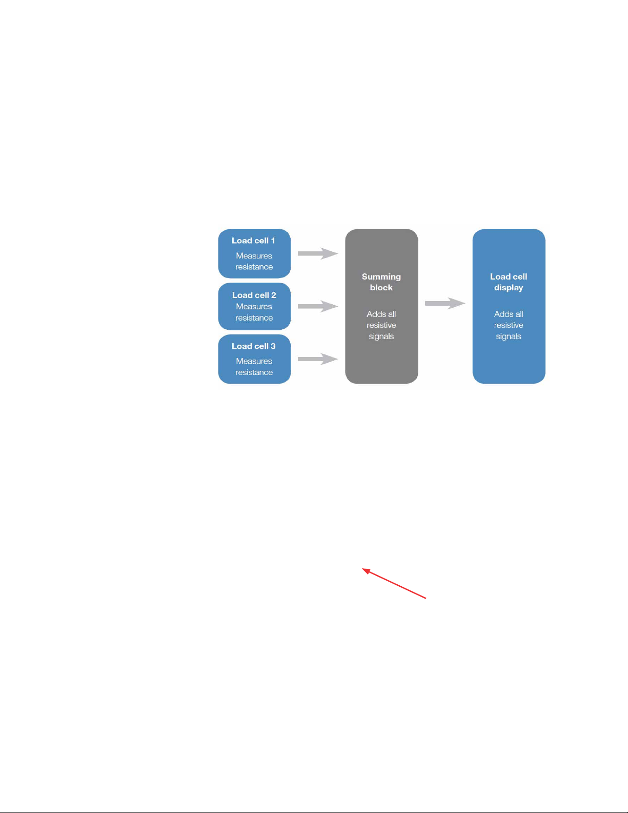
Load cells
Load cells, which are used to determine the weight of the contents
of a S.U.B., are installed on standard 1,000 and 2,000 L S.U.B.
systems, and are available as an option for 50–500 L units. Load cell
retro‑fit kits can also be added to existing S.U.B. units by a certified
service technician. Note: Load cells arrive uncalibrated. The load cell
manufacturer or a qualified technician should calibrate these systems
onsite. The load cell kit comes with three load cells, summing block,
wiring, and a display screen with a choice of several data interfaces
(Figure 1.9).
Figure 1.9. Load cell system overview.
Load cells are typically radial‑mounted in sets of three. The mounting
location (Figure 1.10) varies slightly for each size in order to allow easy
access to the bottom drain or sparging mechanisms and tubing.
Load cell
Figure 1.10. Load cell location.
HyPerforma 2:1 Single-Use Bioreactor User's Guide | 21Thermo Scientific
Chapter 1 | S.U.B. overview
Probe integration
The autoclave tray (Figure 1.11) holds the electrochemical probes and
bellows in place during the autoclave sterilization process. Design
elements include the following.
• Fabricated from stainless steel
• Features a plastic handle for easy transport right out of the
autoclave
• Positions probes on 15% incline for greater probe/membrane
longevity
• Will restrain probe bellows from collapsing during sterilization
• Accommodates two probes
Note: Figure 1.11 shows the autoclave tray used for probes with
™
Kleenpak™ aseptic connectors. Your system may use CPC™
Pall
AseptiQuik
™
aseptic connectors instead. Consult your sales
representative for more information on AseptiQuik connectors.
Handle
Probe assembly
Autoclave tray
for probe kits
Figure 1.11. Autoclave tray and probe assembly.
The probe assembly (Figure 1.12) is an innovative design to package
user‑supplied pH and DO probes for sterilization, and to aseptically
connect them to the BPC. The probe assembly includes a Kleenpak
aseptic connector, molded bellows cover, and threaded probe adapter.
Aseptic
connector
Molded bellows cover
Threaded probe
adapter
Figure 1.12. Probe assembly.
HyPerforma 2:1 Single-Use Bioreactor User's Guide | 22Thermo Scientific

Chapter 1 | S.U.B. overview
Channels for
sparge lines
Cable management systems
The cable management system (Figure 1.13) is available as on option
on 50, 100, 250, 500, and 1,000 L units. It is used to organize various
lines and includes the following components.
• Internal channel for sparge lines
• External channels for feed and base addition lines
• Harvest line hook
Channels for
feed and base
addition lines
Harvest line
hook
Figure 1.13. 500 L S.U.B. with cable management system.
Miscellaneous items
The miscellaneous items listed below are ancillary components
that support the operation of the HyPerforma S.U.B. for cell culture
production, and enhance the overall performance of the complete
system.
• Sampling manifold with luer lock
• S.U.B. temperature/sample port—For resistance temperature
detectors (RTD) calibration/validation
• Sparge line support—Keeps the drilled hole sparge line in
a vertical position for optimal gas flow (Figure 1.14). For more
information see section 2.2, Installation and setup.
HyPerforma 2:1 Single-Use Bioreactor User's Guide | 23Thermo Scientific

Chapter 1 | S.U.B. overview
Figure 1.14. Sparge line support.
• Heavy-duty tubing clamps (typically four or five)—Tu bi ng
clamps (Figure 1.15) are required for pinching off line sets that are
not in use, in order to prevent process fluids from moving into the
line sets. Prior to sterile probe insertion, tubing clamps must be in
place to close off probe ports. For more information, see the BPC
and drive shaft loading instructions in sections 3.2, 3.3, and 3.4.
Figure 1.15. Heavy-duty tubing clamps.
Note: The sparge line support is included with all standard S.U.B.
units. Other items are sold separately. Please contact your sales
representative for more information.
HyPerforma 2:1 Single-Use Bioreactor User's Guide | 24Thermo Scientific

Chapter 1 | S.U.B. overview
Table 1.1. Manufacturers and models of compatible pH/DO probes.
Probe lengths (from O-ring to tip) must not exceed 235 mm O-ring to probe tip
Probe manufacturer
and type
AppliSens DO Z010023525
AppliSens pH Z00102 3551
Mettler Toledo DO
Mettler Toledo pH
Broadley-James DO D140-B220-PT-D9
Broadley-James pH F-635-B225-DH
Hamilton DO 237542
Hamilton pH 238633-2543
Note: Consult the probe manufacturer’s website for appropriate probe cable connection and part number.
1.3 End user and third‑party supplied
components
1. 3 .1 pH and DO probes
Table 1.1 shows the length and diameter requirements for traditional
sensors (probes) that can be integrated into the S.U.B. These
requirements are based on the necessary insertion depth of the probe
when used with the probe ports. Note: The presence of a properly
positioned O‑ring on the probe is critical for use with the S.U.B.
Part number Diameter Thread type
12 mm
(0.47 in.)
12 mm
(0.47 in.)
InPRO 6800/12/220, PN
52200966
405-DPAS-SC-K8S/225, PN
104054481IG
12 mm
(0.47 in.)
12 mm
(0.47 in.)
12 mm
(0.47 in.)
12 mm
(0.47 in.)
12 mm
(0.47 in.)
12 mm
(0.47 in.)
13.5 PG
13.5 PG
13.5 PG
13.5 PG
13.5 PG
13.5 PG
13.5 PG
13.5 PG
Print/lit.
length
235 mm
(9.25 in.)
235 mm
(9.25 in.)
215 mm
(8.46 in.)
195 mm
( 7.6 7 in . )
215 mm
(8.46 in.)
225 mm
(8.85 in.)
225 mm
(8.85 in.)
225 mm
(8.85 in.)
Actual
length
235 mm
(9.25 in.)
235 mm
(9.25 in.)
215 mm
(8.46 in.)
219 mm
(8.62 in.)
214 mm
(8.42 in.)
219 mm
(8.62 in.)
220 mm
(8.66 in.)
220 mm
(8.66 in.)
HyPerforma 2:1 Single-Use Bioreactor User's Guide | 25Thermo Scientific

Chapter 1 | S.U.B. overview
1.3. 2 Controllers
Thermo Scientific products are designed with an open‑architecture
approach to the integration of controls. Our industry‑leading S.U.B.
has been integrated with most controllers on the market, allowing
customers to choose the control system they want, or to reduce
expense by integrating with a controller that is already onsite. In
order to facilitate integration, electrical schematics are provided in the
Equipment Turnover Package (ETP) supplied with the HyPerforma
S.U.B. Companies that offer control solutions in either cGMP or non‑
cGMP format for Thermo Scientific S.U.B. units are listed below.
• ABEC
• Bellco
• Broadley‑James
• Dasgip
• Emerson
• Honeywell
• New Brunswick Scientific
• Pendotech
• Sartorius Stedim Biotech
The HyPerforma 2:1 S.U.B is also available as a complete turnkey
system through Thermo Fisher Scientific. These S.U.B. units may be
provided with integrated controls, pump towers, a control monitor, and
advanced features such as data logging, multiple S.U.B. connections
and optional 21CFR part 11 compliance for cGMP manufacturing. A
variety of single‑use sensors are available for pH, DO and pressure
control. Thermo Fisher Scientific can provide complete, integrated
solutions using the manufacturers listed below.
• Allen Bradley
• Applikon PLC eZ‑controller
• Emerson Delta V
• Finesse PC controller
• Siemens
Contact your local sales representative for more information.
Note: The S.U.B. will work well with any of the various control system
platforms, such as PLC, PC, DCS, or proprietary operating system
based controllers.
HyPerforma 2:1 Single-Use Bioreactor User's Guide | 26Thermo Scientific

Chapter 1 | S.U.B. overview
1.4 BPC features
The cell culture itself is contained inside the BPC (Figures 1.16–1.18).
The chamber is manufactured from film, which is a co‑extruded
structure specifically designed for biopharmaceutical process usage.
All materials are qualified for a broad range of physical, mechanical,
biological, and chemical compatibility requirements. Refer to data
in our BPC Catalog and film validation guides; contact your sales
representative for a copy. The bioreactor BPC is supplied gamma
irradiated.
Operating pressure
The S.U.B. BPC does not operate as a closed system, as it has both
inlet and exhaust filters that are utilized to maintain an environment
for cells to grow without concern for contamination. However,
conditions can be encountered when gas inlet flow rate may exceed
exhaust flow rate. This may be encountered in the unlikely event of a
pressure regulator failure on a gas feed, or when excessive foaming
creates conditions of vent blockage. The S.U.B. BPC is not rated
as a pressure vessel [gas pressure should not exceed 0.03 bar (0.5
psi) within the BPC]. Custom BPCs can be ordered with an optional
single‑use pressure transducer for monitoring the pressure within the
S.U.B. (supplied standard with 1,000 and 2,000 L systems).
Exhaust vent filter
The exhaust vent filter used on 50–1,000 L S.U.B.s is a Pall KA3
series filter utilizing hydrophobic PVDF membranes. To maintain a
sterile connection, the standard BPC is supplied with the filter arrow
pointing toward the BPC. This ensures that the filter vents are outside
of the sterile connection. For users with more demanding applications,
an optional vent filter heater can be used.
™
The exhaust vent filters used on 2,000 L S.U.B.s are Meissner
™
UltraCap
series filters utilizing hydrophobic PVDF membranes. These
filters are provided in normal orientation with the flow arrow on the
filter housing pointing away from the BPC. The normal orientation
provides maximum filter capacity. No side vents are provided.
Condensate must be managed by use of the condenser system or
vent filter heater.
Draining and harvest
The S.U.B. is equipped with a bottom drain line that allows for liquid
harvest by means of peristaltic pump. Connection of the bottom
drain line can be accomplished by using a tubing welder, the quick
connect, or fitting provided. Manipulation of the BPC as the last few
liters of media are removed can minimize liquid hold‑up in the S.U.B.
HyPerforma 2:1 Single-Use Bioreactor User's Guide | 27Thermo Scientific

Chapter 1 | S.U.B. overview
Sparging
Gas to liquid mass transfer in cell culture bioreactors is controlled
by the solubility of the gas in the liquid, its distribution, and the
temperature and pressure. Direct air sparging is a method of providing
for the oxygen requirements of eukaryotic cell cultures. The standard
S.U.B. BPC incorporates a unique single‑use dual sparging design that
allows for optimal aeration of the culture process and effective carbon
dioxide stripping.
Connections
Multiple aseptic connection options exist for S.U.B. users. Standard
BPCs include tubing welder sections, quick connects, and Pall
Kleenpak connections. Note: CPC AseptiQuik connectors are also
available. The BPC is designed with various lengths and dimensions of
thermoplastic tubing for the purpose of adding to and dispensing from
the BPC.
Sampling port
The S.U.B. is equipped with a small volume sample port that is
adjacent to the BPC thermowell. This small‑diameter silicone dip tube
of 152.4 mm length (6 in.) allows low void volume samples to be taken
for cell viability and density, as well as analyte analysis. This dip tube
is supplied with a luer lock connector
(SmartSite™)
that allows for
direct sampling or attachment of various sampling manifolds by use of
standard luer lock connection. Alternatively, manifolds can be welded
onto the C‑Flex
™
sample line using a tubing welder.
Figures 1.16–1.18 on the following page, show the features of all sizes of
2:1 S.U.B. BPCs. For more information about the components labeled
in the figures, see Table 1.2.
HyPerforma 2:1 Single-Use Bioreactor User's Guide | 28Thermo Scientific

Chapter 1 | S.U.B. overview
1
2
3
4
2
3
4
1
2
1
3
4
5
5
5
6
6
7-8
7-8
9
9
10
10
10
Figure 1.16. Standard
BPC for 50, 100, and
250 L systems.
Figure 1.17. Standard BPC for
500 and 1,000 L systems.
Figure 1.18. Standard BPC for 2,000 L systems.
Table 1.2. BPC information for Figures 1.16–1.18.
Item Component Description
1 Exhaust vent filter Single-use capsule filter for exhaust gas exchange
2 Gas overlay port Protected by gas filter
3 Ports For addition of media and other liquids
4 Seal/bearing assembly Links with motor mixer and allows impeller to turn while retaining integrity of the BPC
5 Impeller
Injection-molded plastic, linked to seal/bearing assembly by C-Flex tubing contact
material of the shaft
6 Ports with Kleenpak connectors For integration of standard 12 mm (0.47 in.) monitoring pH and DO probes
6
3
7-8
9
7 Temperature RTD port For integration of temperature probe while retaining integrity of the BPC
8 Sampling port For needleless sampling or connection to sampling manifold
9 Drain port For draining the S.U.B.
10 Gas sparge lines
Sparger integrated into the chamber and protected by gas filters; dual micro sparger
(porous frit) and macro sparger (with open pipe or drilled hole) options are available
Integrates with chiller plate to remove condensate from exhaust; supports effective
11 Condenser system bag
use of 2,000 L systems (can also be used with smaller sizes) S.U.B.s that require
custom gassing strategies and demand higher exhaust rates and longer durations
HyPerforma 2:1 Single-Use Bioreactor User's Guide | 29Thermo Scientific

Chapter 2 | Hardware assembly and setup
Hardware assembly
and setup
2
Chapter contents
2.1 Initial installation preparation
2.2 Installation and setup
HyPerforma 2:1 Single-Use Bioreactor User's Guide | 30Thermo Scientific

Chapter 2 | Hardware assembly and setup
2.1 Initial installation preparation
2.1.1 Hardware shipment and setup
The Single‑Use Bioreactor (S.U.B.) hardware will arrive crated. For
unpacking instructions and detailed contents of the crate, please refer
to the unpacking and assembly instructions, as well as the packaging
drawings, which are included in the shipping crate. Be sure to follow
the unpacking instructions provided and retain all packaging materials.
2.1. 2 Hardware uncrating
The S.U.B. hardware will arrive with the following items:
• Outer support container [platform, tank, and electrical control panel
• Drive shaft, resistance temperature detector (RTD), four probe
• Equipment Turnover Package (ETP), provided on a USB drive
(E‑Box)]
brackets, and standard tool set (spanner wrench and torque
wrench)
(shipped separately)
After uncrating, contact your sales representative immediately if any
damage has occurred.
2.1.3 Site preparation
Electrical connections for units with AC motors and E-Boxes
S.U.B. hardware using AC motors cannot be used on circuits equipped
with Ground Fault Circuit Interrupter (GFCI) circuit protection because
of the potential for nuisance tripping. The electrical plug on the S.U.B.
is a connector that offers a secure ground. These connectors meet
the electrical safety codes for portable equipment and are International
Electrical Code (IEC) rated (meet IEC standard 60309). This plug
provides electrical ground prior to power connection. The supplied
electrical receptacle should be hardwired into the facility by a qualified
electrical technician; for U.S. installations, the receptacle will require the
use of an adapter mounting plate (supplied), which will fit into a two‑
gang box. For additional information on the adapter mounting plate,
please see the ETP. Alternatively, the system can be hardwired directly
into the facility. Note: The yellow plug and receptacle are for 120 VAC
and the blue are for 240 VAC S.U.B.s.
HyPerforma 2:1 Single-Use Bioreactor User's Guide | 31Thermo Scientific

Chapter 2 | Hardware assembly and setup
Electrical connections for systems with DC motors
S.U.B. units using DC motors are not supplied with E‑Boxes. When
using a DC motor, electrical connections must be supplied by a third‑
party integrator.
Outer support container preparation
Each outer support container is shipped directly from the manufacturer
and arrives with various safety mechanisms in place. Follow the
guidelines below to set up the S.U.B. upon arrival.
WARNING: Any procedure that requires the E‑Box to be opened
should be performed with the main electrical disconnect in the
locked out position, and all power sources removed from the E‑Box.
For operator safety, secure the location of the S.U.B. outer support
container by disabling the swivel casters before servicing.
Electrical preparation for 50–2,000 L systems with AC motors
and E-Boxes
1. Using a flat‑head screwdriver, open the E‑Box and locate the
breakers for the pressure sensor, continuous power outlets
non E‑stoppable (2), and continuous power outlets E‑stoppable
(2) (Figure 2.1). These breakers should be in the "on" position
during operation, which will be in the "up" position or pressed in,
depending on the breaker type. For electrical schematics, refer to
the ETP, which is provided on a USB drive.
Figure 2.1. 50–2,000 L S.U.B. E-Box interior.
VFD breaker
Main power
breaker
Temp. display
breaker
Pressure
breaker
E-Stop power
breaker
Continuous power
breaker
HyPerforma 2:1 Single-Use Bioreactor User's Guide | 32Thermo Scientific

Chapter 2 | Hardware assembly and setup
2. Verify that the three‑way motor controller switch is in the middle
3. Close the E‑Box. Use a screwdriver to lock the E‑Box before
4. For S.U.B. hardware units purchased with factory‑installed load
position. For reference:
• The middle position enables the speed control keypad
• The top position is for 0–10 V controllers
• The bottom position is for 4–20 mA controllers
Verify that the position of the two‑way temperature control switch is
in the up position. This will enable the PID temperature controller.
continuing.
cells, the load cells are shipped in the locked position (threaded
up) for equipment protection. Refer to the load cell preparation
instructions later in this section for more information.
2.2 Installation and setup
2.2.1 Preparing load cells
All manual movements of mobile S.U.B. hardware should be over
smooth surfaces, with the S.U.B. empty and disconnected from all
power and gas/feed sources. All load cells must be fully locked down
in order to move the S.U.B.
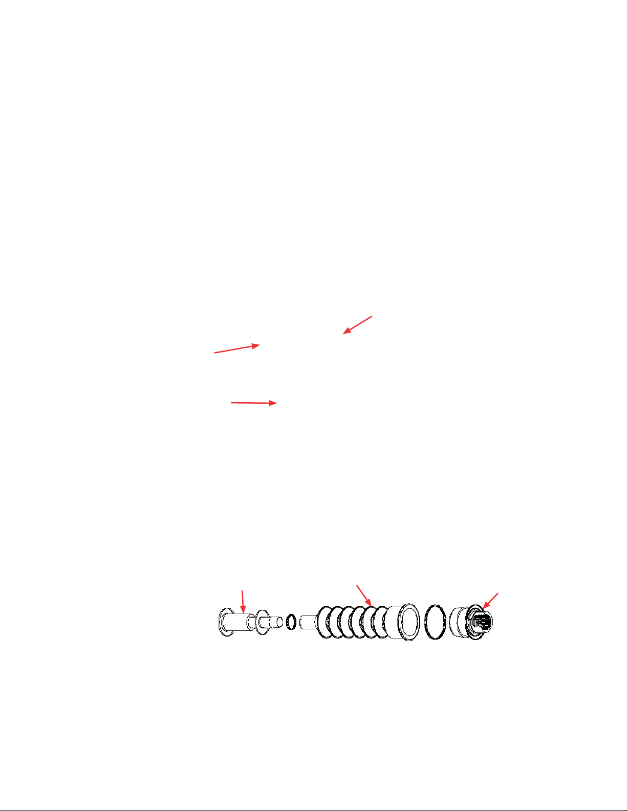
Use the following steps below to prepare load cells for use. Figure 2.2
illustrates the location and components of load cells, which will be
referenced throughout the load cell preparation process.
1. For S.U.B. hardware units purchased with factory‑installed load
cells, the load cells are shipped in the locked position (threaded up)
for equipment protection.
2. To unlock the load cells, remove and discard the delrin slip ring (if
present). Remove the tri‑clamp. Use the small end of the supplied
tool (Figure 2.3) to loosen the lockout nut until the nut is tight
against the base or leg of the S.U.B. Repeat this process for
each load cell until all of the lockout nuts are disengaged from the
lockout posts. Do not reinstall the tri‑clamp.
HyPerforma 2:1 Single-Use Bioreactor User's Guide | 33Thermo Scientific

Chapter 2 | Hardware assembly and setup
Lockout
nut
38.1 mm
(1. 5 in.)
tri-clamp
Lockout
post
Drive shaft
cap end
A
Delrin slip
ring
Figure 2.2. Close-up view of load cells.
Load cell
lockout end
Figure 2.3. Supplied wrench.
3. At this point, the S.U.B. hardware is ready to be prepared for a cell
culture run.
4. For systems with load cell display screens, refer to Appendix B for
information about calibrating load cells.
CAUTION: Do not move the unit (especially when filled) while load cells
are unlocked, as this can damage the load cells.
5. To lock load cells that have been unlocked, hand‑tighten the
lockout nut onto the post. Use the supplied tool to turn the nut an
extra 1/4 turn.
CAUTION: To avoid damaging the load cells, do not over‑tighten the
nut. Assemble a standard stainless 38.1 mm (1.5 in.) tri‑clamp around
the flanges. Complete this process for all load cells.
HyPerforma 2:1 Single-Use Bioreactor User's Guide | 34Thermo Scientific

Chapter 2 | Hardware assembly and setup
2.2.2 Leveling and connecting the system
All manual movements of mobile S.U.B. hardware should be made over
smooth surfaces, with the S.U.B. empty and disconnected from all
power and gas/feed sources. All load cells must be fully locked down
in order to move a S.U.B. Refer to the previous subsection of this guide
for illustrations.
1. Verify that the facility electrical supplies are sufficient to support the
2. Locate the outer support container in the area for the cell culture
3. When monitoring the batch volume, the unit may be placed on a
power requirements of the S.U.B. and ancillary components, such
as controllers or pumps.
run.
weight scale if load cells are not part of the system. Other methods
may be used to measure all incoming and outgoing liquids.
4. Level the platform by disabling the swivel casters on the bottom of
the outer support container. This is accomplished by threading the
leveling feet (at the center of each caster) to the floor.
5. Verify the location of the pH/DO controllers and ensure that the
cable and tubing lengths are sufficient.
WARNING: Risk of electrical shock.
6. Verify that the main power is off and the emergency stop is pulled
out. Note: The emergency stop disconnects all power to the
system. An alarm buzzer will sound when the emergency stop is
activated.
7. Verify that the main motor power switch is in the "off" position.
8. Connect all electrical plugs to facility power. Note: 120
VAC–250 L S.U.B. should be connected to a dedicated 20 A circuit.
Refer to hardware/electrical labels and schematics to ensure proper
electrical voltage is connected to the S.U.B. The main power switch
can now be turned on.
9. For resistive 50, 100, and 250 L systems, verify that the
temperature controller is off. The display should be flashing in the
stand‑by position.
HyPerforma 2:1 Single-Use Bioreactor User's Guide | 35Thermo Scientific

Chapter 2 | Hardware assembly and setup
10. For 1,000 L units only, the water jacket ports are removed for
shipping. Attach the ports to the S.U.B. using the tri‑clamps
provided (Figure 2.4).
Figure 2.4. Attaching water jacket port using tri-clamp.
Inlet port
11. Connect water inlet and outlet lines from the temperature control
unit quick connects to the jacket (Figure 2.5). For 50, 100, 250, 500,
and 2,000 L units, the inlet is typically on the left side if you are
facing the connectors. For the 1,000 L S.U.B. unit, the inlet is the
lower connection, and the outlet is the upper.
Outlet port
Figure 2.5. Inlet and outlet ports.
HyPerforma 2:1 Single-Use Bioreactor User's Guide | 36Thermo Scientific

Chapter 2 | Hardware assembly and setup
12. Insert the sparge line support (Figure 2.6) into the bottom of
the S.U.B. unit, directly below where the sparger will be placed.
This component holds the sparge line vertically for maximum
effectiveness. The sparge line can be wound through the coil of the
holder to keep the sparger properly oriented.
Figure 2.6. Sparge line support.
2.2.3 Verifying drive shaft segments for 2,000 L systems
The 2,000 L S.U.B. is supplied with a special drive shaft that differs in
appearance and material when compared to the metallic shafts used in
smaller S.U.B. sizes. Due to the higher mechanical stress generated in
2,000 L S.U.B.s, these systems require:
• Drive shafts made of carbon fiber composites to reduce the weight
of the long shaft
• Special quick connect designs to reduce joint fatigue in multiple‑
segment drive shafts
Note: 2,000 L systems include two‑piece drive shafts. Before starting
to load a drive shaft, verify that the drive shaft serial numbers match on
both shaft segments.
Always maintain a log history of the drive shaft and confirm that it
has sufficient life remaining. For warranty purposes, users must
show documentation of proper drive shaft use. A sample log
for documenting drive shaft use is provided in Appendix D of this
publication. If the age or history of a drive shaft is questionable, it
should be discarded.
HyPerforma 2:1 Single-Use Bioreactor User's Guide | 37Thermo Scientific

Chapter 3 | Operating information
3
Operating information
Chapter contents
3.1 General system operating information
3.2 BPC and drive shaft loading instructions for 50, 100, and
250 L systems
3.3 BPC and drive shaft loading instructions for 500 and 1,000 L
systems
3.4 BPC and drive shaft loading, and condenser system setup
instructions for 2,000 L systems
3.5 Probe preparation and insertion
3.6 Cell culture operating instructions
3.7 Verification procedures
HyPerforma 2:1 Single-Use Bioreactor User's Guide | 38Thermo Scientific

Chapter 3 | Operating information
3.1 General system operating information
3.1.1 BPC preparation
Each outer support container is designed for a specific BioProcess
Container (BPC). Confirm that the correct volume and type of BPC
is being used for the corresponding volume outer support container.
Sections 3.2, 3.3, and 3.4 cover the installation and setup of BPCs.
Follow these instructions in the order in which they are presented.
3.1. 2 BPC handling instructions
If you are using a sharp object when opening outer polybags, take care
to avoid damaging the BPC. Do not drag containers over corners or
sharp objects. Do not lift the container by the corners or top seams.
Carefully coil the tubing on top of the BPC to prevent puncturing the
container with cable ties or clamps. Use cushioning between the tubing
and the container in storage and transport.
3.1. 3 BPC operating information
Working volume
Each Single‑Use Bioreactor (S.U.B.) is designed for a specific working
volume range. The minimum working volume and the rated working
volume are listed in the specification tables provided in Chapter 4
of this user's guide. The total volume listed includes the headspace
needed for proper aeration and gas management. Actual working
volumes should not exceed the indicated rated working volumes by
more than 10%.
CAUTION: Operating 2:1 S.U.B.s at working volumes less than
50% of the rated volume without consultation from Thermo
Fisher Scientific engineers can result in damage to the BPC
and/or the S.U.B. hardware.
Operating pressure
The BPC does not operate as a closed system; it has both inlet and
exhaust filters that are utilized to maintain a sterile environment for cell
growth. However, conditions can be encountered when the gas inlet
flow rate may exceed the exhaust flow rate. This may be encountered
in the unlikely event of a pressure regulator failure on a gas feed, or
when excessive foam within the bioreactor creates a vent blockage.
HyPerforma 2:1 Single-Use Bioreactor User's Guide | 39Thermo Scientific

Chapter 3 | Operating information
WARNING: The BPC is not rated as a pressure vessel. Gas
pressure within the BPC headspace should not exceed 0.03 bar
(0.5 psi) at any time. Pressure above 0.03 bar (0.5 psi) may result in
BPC damage or personal injury.
• More demanding applications may warrant an optional exhaust vent
heater.
• If foaming is excessive in your cell culture process, it is best to
reduce the operating volume of the process to 80% of maximum
rated working volume of the S.U.B. system being used to provide
greater headspace volume.
• Single‑use pressure transducers are available on custom S.U.B.
configurations. This technology combined with high‑level control
systems (common with industrial applications) can regulate gas
pressure within the confines of the S.U.B.
Aeration
Gas to liquid mass transfer in cell culture bioreactors is controlled
by the solubility of the gas in the liquid, its distribution, and the
temperature and pressure. Direct air sparging provides for the oxygen
requirements of eukaryotic cell cultures. It allows optimal aeration of the
culture process and effective carbon dioxide
stripping.
The standard BPC is designed with special spargers that produce
very efficient mass transfer of oxygen and typically will require much
less gas inflow than conventional spargers. Gas inflow should only
be limited to prevent foam generation and excessive pressure within
the BPC. Gas flow rates supplied as overlay should also be reduced
as much as possible or eliminated, which will minimize both liquid
evaporation and demand on the exhaust filter. Ideally, this will reduce
the likelihood that gas inflows will exceed gas outflow of the system
and reduce the occurrence of foam in the headspace that may plug the
exhaust filter. For more information, refer to the "Operating pressure"
section on the previous page, and section 3.6.8 of this guide.
Aseptic connections
The most commonly recommended process for making connections
to tubing lines is with an aseptic tubing fuser. Other connection
options are available as a custom BPC assembly. By following the
recommended tubing welder operating instructions, successful
connections can be made for filling, supplementing, sampling, or
dispensing from the BPC as needed.
HyPerforma 2:1 Single-Use Bioreactor User's Guide | 40Thermo Scientific

Chapter 3 | Operating information
Draining and harvest
The S.U.B. is equipped with a bottom drain line that allows for liquid
harvest by means of peristaltic pump. Connection of the bottom drain
line can be accomplished by use of a tubing welder or the fitting that is
provided. The bottom drain exits the BPC at the lowest vertical position
on the side of the S.U.B. This allows for easy access for the user and
minimizes the accumulation of cells in the area of the drain during the
cell culture run. Manipulation of the BPC as the last few liters of media
drain will minimize liquid hold‑up within the S.U.B. The 2,000 L S.U.B. is
provided with a 25.4 mm (1 in.) bottom drain near the center line of the
tank bottom.
3.1.4 Hardware operating information
Heating performance
Heating times for S.U.B. systems vary based on liquid volume and
temperature, ambient or heating liquid temperature, sparging rate, and
mixing rate. For heating times, see Table 3.1.
WARNING: Do not heat the system if the BPC is not at 50%
liquid volume or greater. Batch temperature should not exceed
40°C.
Table 3.1. Approximate heating times for 2:1 S.U.B. systems. Ambient temperature of 25°C.
Liquid batch
System
50 L electric 25–50 L 456 N /A 18.2–9.2 W/L 5°C 37°C N/A–4.3 hr
50 L jacketed 25–50 L 2800 TF2500 112– 5 6 W/ L 5°C 37°C 0.8–1.1 hr
100 L electric 50–100 L 865 N/A 17.3–8.7 W/L 5°C 37°C N/A– 4.9 hr
100 L jacketed 50–100 L 2800 TF2500 56–28 W/L 5°C 37°C 1.2 –1.9 hr
250 L electric 125–250 L 1358 N/A 10.9–5.4 W/L 5°C 37°C N/A –7. 5 h r
250 L jacketed 125–250 L 2800 TF5000 22.4–11.2 W/L 5°C 37°C 2.1– 3.1 h r
500 L jacketed 250–500 L 6100 TF10000 24.4–12.2 W/L 5°C 37°C 1.5–2.6 hr
1,000 L jacketed 500–1,000 L 22500 TF24000 45 –22.5 W/L 5°C 37°C 1.3 –1.8 hr
2,000 L jacketed 1,000–2,000 L 22500 TF24000 22.5–11.3 W/L 5°C 37°C 2–2.8 hr
volume (half
[min.]–full)
Watts TCU
TCU watts/L
(half–full)
Initial
liquid
temp.
Liquid
target
temp.
Time
(half–full)
HyPerforma 2:1 Single-Use Bioreactor User's Guide | 41Thermo Scientific

Chapter 3 | Operating information
Protective earth grounding for units with AC motors
For units with AC motors, protective earth grounding for the S.U.B.
hardware system and the controller is provided through the ground
terminal of the power plug. Source power to the controller must
provide protective earth grounding to this terminal in order to minimize
the hazard of a possible shock in the occurrence of a fault condition.
Please refer to Appendix A for information about electrical receptacles.
A ground wire is provided underneath the S.U.B. and must be tied to
the controller before operation.
Agitation control interface for units with AC motors and
electrical box enclosures
The agitation control interface utilizes an LED digital display to indicate
stirring speed in units of revolutions per minute (rpm). Power is supplied
to the motor by a two‑position power switch that is illuminated in green
when turned to the on position (right position). The agitation should
not be operated at volumes less than 50%. Stirring speed is adjusted
using the up and down arrows on the agitation keypad interface on
the control panel, or using the settings on an integrated third‑party
controller. Note: Due to the auto‑restart capabilities of the S.U.B., the
green start button on the keypad has been disabled; however, the red
stop button on the keypad is active.
If the red stop button has been used to stop the motor, the controller
can be reset and agitation restarted by using the main motor toggle
switch on the left side of the control panel. For more information, see
the illustrations in the control panel detail in section 4.3.
Circuit protection for units with AC motors
Electrical components of the S.U.B. are equipped with circuit
protection. The variable frequency drive used to power the mixer
motor is protected by the use of a 10 A double pull resettable breaker
with a type C time delay (5–10 x LN). Other components, such as
the temperature controller and heating element, are protected with
resettable breakers.
In the case of an electrical fault condition, these safety devices
are designed to protect the user from electrical shock and prevent
electrical system components from being damaged. Fuses can be
replaced and/or the breakers reset once the fault condition is resolved.
HyPerforma 2:1 Single-Use Bioreactor User's Guide | 42Thermo Scientific

Chapter 3 | Operating information
Electrical breaker notes:
• The normal "on" setting for these breakers is in the up position.
• A tripped breaker will be in the mid position.
• The "off" setting is in the fully down position.
• To reset a tripped breaker, it must first be moved from the mid
position to the "off" setting (fully down position) before moving it to
the "on" setting (fully up position).
Scales and weighing systems
Monitoring liquid volume within the S.U.B. during operation can be
critical in cell culture applications that involve nutrient media feeds. This
can also be a useful method for increasing the scalability of the S.U.B.,
by starting the process run at minimum operating volume. The ability
to track operating volume by use of load cells or weigh scales allows
the user the ability to control liquid volume and cell density as the
bioreactor is increased to rated working volume during the process run.
A load cell kit for weight/volume measurement is available for all S.U.B.
units, which can be installed at the factory or can be added later by
a certified service technician. The load cell kit comes with three load
cells, summing block, wiring, and display with a choice of several
interfaces.
Refer to Appendix B for load cell display calibration instructions.
Ensure that load cells are locked down before any movement of
the S.U.B. unit.
To lock the load cells before transporting any size S.U.B., follow the
steps below and refer to Figures 2.2 and 2.3 in section 2.2.1.
1. Hand‑tighten the load cell lockout nut onto the load cell lockout
post. You may need to use the small end of the supplied wrench to
loosen the load cell lockout nut from the bottom of the base.
2. After the nut is hand‑tightened against the post, use the small end
of the supplied wrench to turn it an extra 1/4 turn.
CAUTION: To avoid damaging the load cell, do not overtighten
the nut.
3. Assemble a standard stainless 28.6 mm (1.5 in.) tri‑clamp around
the flanges.
4. Repeat steps 1 through 3 for all load cells on the S.U.B.
HyPerforma 2:1 Single-Use Bioreactor User's Guide | 43Thermo Scientific

Chapter 3 | Operating information
3.1.5 External data logging and control
Digital display weighing scales can be sourced from manufacturers
such as Mettler Toledo. Bench top scales are commonly used to
measure the amount of bulk source media stored in a smaller‑volume
BPC as it is transferred by peristaltic pump into the S.U.B.
Floor scales can be used to measure the fluid content within the S.U.B.
This is accomplished by rolling the S.U.B. onto the scale platform and
leveling the S.U.B. skid once in position.
The S.U.B. hardware systems are designed to allow advanced users to
control all aspects of the operation of the bioreactor. Contact technical
support for Thermo Scientific HyPerforma products general integration
guidance.
3.2 BPC and drive shaft loading instructions for
50, 100, and 250 L systems
3.2.1 Initial BPC loading steps for 50, 100, and 250 L
systems
Each outer support container is designed for a specific BPC. Verify
that the correct volume and type of BPC is being used for the
corresponding volume outer support container. Use the following steps
to install and set up the BPC.
1. Remove the irradiated BPC from the protective double polybags
(Figure 3.1). Remove the cable ties from the drain line.
2. Load the BPC from the top into the outer support container,
avoiding any sharp edges that may damage the BPC (Figure 3.2).
3. Orient the BPC with the bearing port up and toward the motor drive
with the aseptic connector probe ports facing the bottom access
cutout.
4. Place the bearing port into the bearing port receiver (Figure 3.3),
close the door, and close the clamp.
HyPerforma 2:1 Single-Use Bioreactor User's Guide | 44Thermo Scientific

Chapter 3 | Operating information
Figure 3.1. BPC removed from
protective polybags.
Figure 3.2. BPC loading.
Figure 3.3. Bearing port insertion.
5. Use the back access window to route the side and bottom ports
through the opening in the outer support container (Figure 3.4).
6. Route the sparge lines, bottom drain, and sampling lines through
the appropriate openings (Figures 3.5 and 3.6).
7. Route the sparge lines through the bottom plate and loop them
around the sparge line holder (Figure 3.5).
Figure 3.4. Bottom line access.
HyPerforma 2:1 Single-Use Bioreactor User's Guide | 45Thermo Scientific
Figure 3.5. Sparge line setup.

Chapter 3 | Operating information
Figure 3.6. Drain line and port setup.
8. If a cable management system is available (see system shown
in Figure 3.7), attach the lines to the appropriate inlet ports
(Figure 3.8).
Figure 3.7. Cable management
system in use.
Figure 3.8. Incoming line connection
to inlet ports.
9. Connect the incoming gas feed lines to both the overlay filter and
the sparger filter. Ensure that the filters are located above the
maximum liquid level (Figure 3.9).
HyPerforma 2:1 Single-Use Bioreactor User's Guide | 46Thermo Scientific

Chapter 3 | Operating information
Figure 3.9. Inserting lines into the
cable management system channels.
10. Inflate the BPC with air through the overlay filter, but do not exceed
25 standard liters per minute (slpm) or 0.03 bar (0.5 psi) internal
BPC pressure. Inflation time is approximately 10–20 minutes. Time
will vary based on flow rate, inlet pressure, and container volume.
As the BPC inflates, ensure that the ports, drain, and sparge lines
are properly oriented in the support container.
WARNING: The BPC is not rated as a pressure vessel. The BPC
should not be allowed to become tight during inflation or operation.
DO NOT EXCEED 0.03 bar (0.5 psi) within the BPC or it could fail. For
reference, the BPC will appear to be tight at 0.007 bar (0.1 psi). See
Tables 3.7 and 3.8 in section 3.6.8 for recommended air flow rates. The
operating pressures at the level of the S.U.B. are of primary importance
and these values must be adhered to.
11. As the container fills with air, check to make sure the sparge lines
are properly aligned.
Sparge line note: While a sparge line check valve is provided
for each sparge line, it is not uncommon for some fluid to bypass
check valves during typical use. Elevating the filter will reduce the
chance that the filter is exposed to liquid.
12. Use the four bottom cutouts located at the base of the support
container as a reference to align the hanging tab on the BPC
(Figure 3.10).
CAUTION: Do not attach cutouts to any of the bottom hanging
tabs; only use them for reference in aligning the BPC within the
tank. Doing so may potentially stretch and/or tear the film.
HyPerforma 2:1 Single-Use Bioreactor User's Guide | 47Thermo Scientific

Chapter 3 | Operating information
Figure 3.10. Hanging tab and hook.
13. Position the bottom side drain, pulling out and downward to
position the port toward the bottom edge of the S.U.B.
14. Align the row of probe ports within the access window (Figure 3.11).
Note: Verify all port clamps are closed and located as close as
possible to the body of the BPC.
Figure 3.11. Aseptic connector alignment.
15. Connect the media ground clip to the stainless steel insert in the
sample line on the BPC. This grounds the media inside the BPC
and helps eliminate electrostatic charge (Figure 3.12).
Ground clip
connection
Figure 3.12. Media ground clip
connection.
HyPerforma 2:1 Single-Use Bioreactor User's Guide | 48Thermo Scientific

Chapter 3 | Operating information
3.2.2 Drive shaft insertion for 50, 100, and 250 L
systems
WARNING: Before you insert the drive shaft, the BPC must be
adequately inflated so that it is sitting upright in the outer support
container.
Figure 3.13 illustrates the components of the motor and mixing
assembly. The parts labeled on the figure will be referenced
throughout the drive shaft insertion process. Use the steps on the
following pages to insert the drive shaft.
Motor
cap
Hollow
passthrough
Safety
cover
Drive
shaft
Drive shaft
head
Motor drive
keyway
Latch pin
Motor
Figure 3.13. Motor and mixing assembly.
1. Remove the latch pin from the safety cover over the mixing
assembly and open the cover. Unscrew the motor cap covering the
hollow pass‑through of the motor (Figure 3.14).
HyPerforma 2:1 Single-Use Bioreactor User's Guide | 49Thermo Scientific

Chapter 3 | Operating information
Figure 3.14. Removing motor cap.
2. Insert the drive shaft through the hollow pass‑through of the motor
assembly in the following manner (Figures 3.15–3.18).
• Use two hands to load the drive shaft through the top of the
motor assembly; a slight back‑and‑forth twisting motion will aid
in insertion and avoid stretching the impeller tubing (Figures 3.15
a n d 3.16 ).
Figure 3.15. Loading drive shaft.
Figure 3.16. Twisting drive shaft to aid
insertion.
HyPerforma 2:1 Single-Use Bioreactor User's Guide | 50Thermo Scientific

Chapter 3 | Operating information
• When approximately 50.8–76.2 mm (2–3 in.) of the shaft remains,
twist back and forth slightly to engage the impeller (Figure 3.17).
• When approximately 25.4–50.8 mm (1–2 in.) of the shaft remains,
twist back and forth slightly to engage the bearing assembly.
• When approximately 6.4 mm (0.25 in.) of the shaft remains, twist
to align the motor drive keyway with one of the four outer slots
on the drive shaft head (Figure 3.18).
Figure 3.17. Engaging impeller.
3. Directly couple the drive shaft to the motor drive (Figures 3.19–3.21).
• Place the motor cap on the hollow pass‑through and hand‑
tighten clockwise (Figure 3.19).
Figure 3.19. Replacing motor cap.
Figure 3.18. Drive shaft head aligned.
HyPerforma 2:1 Single-Use Bioreactor User's Guide | 51Thermo Scientific

Chapter 3 | Operating information
• Tighten the motor cap by placing a spanner wrench on the
hollow pass‑through and tighten the motor cap using the
supplied torque wrench (Figure 3.20). Wrench note: The
torque wrench is a standard 10 mm (3/8 in.) square drive, and is
calibrated at the factory at 150 in‑lb.
Figure 3.20. Tightening cap.
• Remove the wrenches from the system and place in the storage
holders.
• Close the safety access cover and insert the latch pin
(Figure 3.21).
Figure 3.21. Replacing and latching cover.
HyPerforma 2:1 Single-Use Bioreactor User's Guide | 52Thermo Scientific

Chapter 3 | Operating information
3.2.3 Final installation steps for 50, 100, and 250 L
systems
1. The air supply to the overlay can be turned off once the drive shaft
has been inserted.
2. Optional: Wrap and secure the vent filter heater on the exhaust filter.
Connect the heater to the controller and verify that it is plugged into
an appropriate 120 or 240 VAC outlet, then connect the power cord
to the controller. Note: The controller is preset to 50°C.
3. Secure the exhaust vent filter on its holder (Figure 3.22).
Note: Some custom BPCs are supplied with dual exhaust vents.
The vent bracket can accommodate 10 in. and 4 in. filters in either
single or dual configuration.
Figure 3.22. Vent filter installation.
4. Attach the overlay sparge line and any other lines to the cable
management system, if available (Figure 3.23). Then, position and
close a bar clamp on the bottom drain line as close as possible to
the BPC port (Figure 3.24).
HyPerforma 2:1 Single-Use Bioreactor User's Guide | 53Thermo Scientific

Chapter 3 | Operating information
Figure 3.23. Optional cable
management system on a S.U.B. unit.
Figure 3.24. Bar clamp installation.
5. Remove the plastic insert located in the thermowell, if present.
6. Insert the resistance temperature detector (RTD) or selected
temperature sensor into the thermowell (Figures 3.25 and 3.26).
• Place a small amount of glycerol (0.5 mL) in the well to aid in
heat transfer. The glycerol also acts as a lubricant, which helps
with probe insertion.
• The sensor should be inserted until the base of the probe meets
the mouth of the thermowell. Rotate the probe either clockwise
or counter‑clockwise to aid insertion.
• Secure by twisting the luer lock collar, if provided. The
thermowell will stretch slightly when the RTD is seated.
HyPerforma 2:1 Single-Use Bioreactor User's Guide | 54Thermo Scientific

Chapter 3 | Operating information
Figure 3.25. Sensor insertion.
7. Optional: Connect a pressure sensor to the aseptic connector
at the top of the BPC. Then connect the appropriate pressure
transducer cable to the third‑party controller.
8. Refer to section 3.5.3 for probe insertion instructions.
3.3 BPC and drive shaft loading instructions for
500 and 1,000 L systems
3.3.1 Initial BPC loading steps for 500 and 1,000 L
systems
Checkpoints prior to BPC loading
9 The correct volume BPC is being used for the corresponding
volume outer support container.
9 The outer support container is stationary with the casters locked
into place. BPC loading may require operators to step inside the
bioreactor, and the unit must be stationary for the safety of both the
operator and equipment.
9 Two operators are available for ease in BPC loading.
9 A ladder or other means of elevation is available for drive shaft
insertion.
Figure 3.26. Securing sensor.
Use the following steps to install and set up the BPC.
1. Open the door on the bioreactor support container and reach
inside to open the clamp on the bearing port receiver located below
the motor (Figures 3.27 and 3.28).
HyPerforma 2:1 Single-Use Bioreactor User's Guide | 55Thermo Scientific

Chapter 3 | Operating information
Figure 3.27. Opening the bioreactor door.
Figure 3.28. Close-up of bearing
receiver clamp.
2. Remove the irradiated BPC from the protective double polybags
(Figure 3.29). Do not remove the polybags from the line sets at this
stage, as the BPC may become difficult to manage. Do not allow
the BPC or line sets to touch the floor.
3. Reach into or step inside the outer support container with the
front face (bearing port side) of the BPC oriented toward the motor
(Figure 3.30).
Figure 3.29. BPC removed from
protective polybags.
Figure 3.30. Bearing port
orientation.
4. Place the top line sets, still in polybags, over the top edge of the
tank (Figure 3.31). This will keep the container from being restricted
during the air inflation step.
HyPerforma 2:1 Single-Use Bioreactor User's Guide | 56Thermo Scientific

Chapter 3 | Operating information
Figure 3.31. Line sets on edge of tank.
5. Load the container bearing port into the receiver (Figure 3.32).
Close the door and clamp it shut (Figure 3.33).
Figure 3.32. Bearing port in receiver.
6. Remove the bubble wrap from the sparger filters. Guide the sparge
inlet lines and filters through the bottom cutouts in the outer
support container (Figure 3.34). The operator can reach just below
the S.U.B. to further extend the sparge lines from the cutouts
(Figure 3.35).
Figure 3.33. Door clamped shut.
HyPerforma 2:1 Single-Use Bioreactor User's Guide | 57Thermo Scientific

Chapter 3 | Operating information
Figure 3.34. Sparge line insertion.
Figure 3.35. Sparge line extension.
7. Pass the bagged drain line set and temperature/sampling port
set through the large cutout in the front of the outer support
container (Figure 3.36). Extend the drain line set through the cutout
(Figure 3.37).
Figure 3.36. Drain/sampling line set
insertion.
Figure 3.37. Drain/sampling line
extension.
8. Connect the pressure transducer to the monitor. After the display
has stabilized, tare the monitor. Note: The monitor should be
allowed to warm up for 30 minutes before taring. Verify that the
monitor reads zero.
HyPerforma 2:1 Single-Use Bioreactor User's Guide | 58Thermo Scientific

Chapter 3 | Operating information
9. The BPC must be partially inflated until it is sitting upright. This
allows proper insertion of the drive shaft and aids in the proper
alignment of the BPC in the outer support container.
• Attach the air supply to the overlay gas inlet line. Note: Air
pressure to the overlay gas line on the S.U.B. BPC should be
less than 25 slpm or 0.2 bar (3 psi).
• Begin air inflation through the overlay gas line. Filling the
container with air takes approximately 15–20 minutes before
drive shaft insertion can begin. Times will vary based upon flow
rate and inlet pressure.
• Steps 10 through 13 can be completed while the BPC is filling
with air.
WARNING: The BPC is not rated as a pressure vessel. DO NOT
EXCEED 0.03 bar (0.5 psi) within the BPC or the system could fail,
causing personal injury or damage to equipment. DO NOT leave the
BPC unattended while inflating. See Tables 3.7 and 3.8 in section 3.6.8
for recommended air flow rates. The operating pressures at the level
of the S.U.B. are of primary importance and these values must be
adhered to.
10. Attach the incoming gas supply to the sparger gas inlet line. Note:
Air pressure to the sparger on the BPC should not exceed 0.55
bar (8 psi). While a sparge line check valve is provided for each
sparge line, some fluid may bypass check valves during typical
use. Elevating the filter to ensure that it is not at the low point of the
sparge line will reduce the chance that the filter is exposed to liquid.
11. Tare the load cell display before proceeding.
12. Attach all of the hanging tabs on the BPC to the hooks on the
bottom of the outer support container to help position the ports
(Figures 3.38 and 3.39).
CAUTION: For the 500 L systems, only attach the front 2 hanging
tabs to the pins to assist in aligning the probe belt, drain port, and
spargers.
HyPerforma 2:1 Single-Use Bioreactor User's Guide | 59Thermo Scientific

Chapter 3 | Operating information
Figure 3.38. Hanging tab and hook.
Figure 3.39. Attaching tab.
13. Verify that the sparger filter and spargers remain in the correct
position. It is recommended that users secure the hanging tabs
on the front BPC panel first. This way the door will not be an
obstruction when connecting the last set of hooks.
14. Remove the protective packaging from the exhaust vent filters
(Figure 3.40).
Figure 3.40. Removing protective packaging.
HyPerforma 2:1 Single-Use Bioreactor User's Guide | 60Thermo Scientific

Chapter 3 | Operating information
3.3.2 Drive shaft insertion for 500 and 1,000 L systems
The drive shaft is constructed in multiple segments, which must be
assembled and inserted in pieces. Operators should be elevated (i.e.
with the use of a ladder) to effectively assemble and insert the drive
shaft.
CAUTION: Review ceiling height requirements in Chapter 4 of this
user's guide before trying to insert the drive shaft.
Figure 3.41 illustrates the components of the motor and mixing
assembly. The parts labeled on the figure will be referenced throughout
the drive shaft insertion process. Use the steps in this section to
assemble and insert the drive shaft.
Motor
cap
Hollow
passthrough
Safety
cover
Drive
shaft
Drive shaft
head
Motor drive
keyway
Latch pin
Motor
Figure 3.41. Motor and mixing assembly.
1. Prepare the hollow pass‑through by first removing the latch
pin on the safety cover (Figure 3.42), opening the safety cover
(Figure 3.43), and removing the motor cap of the mixing assembly
(Figure 3.44).
HyPerforma 2:1 Single-Use Bioreactor User's Guide | 61Thermo Scientific

Chapter 3 | Operating information
Figure 3.42. Latch pin removal. Figure 3.43. Opening safety cover.
Figure 3.44. Cap removal.
2. Verify that the two or three segments of the drive shaft, all with
matching serial numbers, are located in the drive shaft holders
on the side of the outer support container. For the three‑piece
drive shaft loading described here, the segments will be referred
to as upper (the segment with the drive shaft head), middle (the
segment with the internal/external threads on each end) and lower
(the segment with the square end). For 1,000 L systems, lubricate
the threaded ends with a light coat of food‑grade anti‑seize with
each use. Each time drive shafts are assembled and used,
operators must verify that the segments have matching
serial numbers.
3. First, insert the lower segment through the hollow pass‑through
of the mixer drive (Figure 3.45). Slide the latch pin from the motor
assembly into the shaft to prevent it from falling into the tube
(Figure 3.46). Assemble the middle and lower segments of the
drive shaft by joining them with a twisting motion, fastening the two
segments together (Figure 3.47).
Note: Segmented shafts are left‑threaded (reverse‑threaded) to avoid
loosening during operation.
HyPerforma 2:1 Single-Use Bioreactor User's Guide | 62Thermo Scientific

Chapter 3 | Operating information
Figure 3.45. Inserting lower section.
Figure 3.47. Segment assembly.
Figure 3.46. Latch pin in shaft.
4. Place one wrench on the flat area in the middle drive shaft segment
and another wrench on the lower segment, then tighten the
connection using a counterclockwise rotation (Figure 3.48). After
the segments are secure, return the wrenches to the tool holder.
CAUTION: Do not over‑tighten; a snug fit is sufficient. Remove the
latch pin.
HyPerforma 2:1 Single-Use Bioreactor User's Guide | 63Thermo Scientific

Chapter 3 | Operating information
Figure 3.48. Tightening of shaft
connections.
5. Load the partially‑assembled drive shaft through the hollow pass‑
through and hold it in position with the latch pin. Obtain the upper
segment of the drive shaft and assemble it to the middle segment
in the manner described previously.
6. Using two hands, carefully guide the assembled drive shaft into the
BPC using a slight back and forth twisting motion. Note: It may be
necessary for another operator to assist with drive shaft insertion.
As one operator inserts the drive shaft, another operator should
carefully manipulate the impeller as the end of the drive shaft
begins to couple with the impeller.
• When 50.8–76.2 mm (2–3 in.) of the shaft remains, twist slightly
to engage the impeller (Figure 3.49).
Figure 3.49. Drive shaft insertion.
HyPerforma 2:1 Single-Use Bioreactor User's Guide | 64Thermo Scientific

Chapter 3 | Operating information
• When 25.4–50.8 mm (1–2 in.) of the shaft remains, twist slightly
to engage the bearing assembly.
• When 6.35–12.7 mm (0.25–0.50 in.) of the shaft remains, twist
to align the motor drive keyway with one of the four outer slots
on the drive shaft head (Figure 3.50).
Figure 3.50. Drive shaft head aligned.
7. Directly couple the drive shaft to the motor by placing the motor
cap back on the hollow pass‑through and tighten.
8. Tighten the motor cap by placing the spanner wrench
counterclockwise on the hollow pass‑through and tighten using the
supplied torque wrench (Figure 3.51). Wrench note: The torque
wrench is a standard 10 mm (3/8 in.) square drive, and is calibrated
at the factory at 150 in‑lb.
Figure 3.51. Tightening motor cap with wrenches.
HyPerforma 2:1 Single-Use Bioreactor User's Guide | 65Thermo Scientific

Chapter 3 | Operating information
9. Verify that the wrenches have been removed from the system and
returned to the storage holders.
10. Close the safety access cover and insert the latch pin.
3.3.3 Final installation steps for 500 and 1,000 L
systems
1. Secure the exhaust vent filters to the top‑mounted holders
(Figure 3.52), or if you are using elevated dual exhaust filters, use
the adapter piece and extended filter bracket (Figure 3.53). Note:
500 L BPCs and some custom BPCs are supplied with dual
exhaust vents. The vent bracket can accommodate 10 in. and 4 in.
filters in either single or dual configuration.
Figure 3.52. Vent filter. Figure 3.53. Extended dual filter bracket.
2. Fully extend the drain line set through the front cutout and attach
the probe shelf.
3. Remove the polybag from the drain line set, position the line clamp
as close as possible to the BPC port, and close the clamp. Use a
cable tie around the clamp to ensure it does not open.
4. Align the aseptic connector ports through the front access window
(Figure 3.54).
HyPerforma 2:1 Single-Use Bioreactor User's Guide | 66Thermo Scientific

Chapter 3 | Operating information
Figure 3.54. Aseptic connector port alignment.
5. Remove the plastic insert located in the thermowell, if present.
6. Insert a resistance temperature detector (RTD) or another selected
temperature sensor into the thermowell (Figure 3.55).
• Place a small amount of glycerol (0.5 mL) in the thermowell to aid
in heat transfer. The glycerol also serves as a lubricant and aids
in insertion.
• The sensor should be inserted until the base of the RTD meets
the mouth of the thermowell.
• Secure by twisting the luer lock collar, if provided; the thermowell
will stretch slightly when the RTD is seated (Figure 3.56).
Note: Verify that all port clamps are closed and located as close as
possible to the body of the BPC.
Figure 3.55. Inserting a temperature sensor.
HyPerforma 2:1 Single-Use Bioreactor User's Guide | 67Thermo Scientific
Figure 3.56. Securing the temperature sensor.

Chapter 3 | Operating information
7. Optional: Connect a pressure sensor to the CPC aseptic connector
at the top of the BPC. Then connect the appropriate pressure
transducer cable to the third‑party controller.
8. Refer to section 3.5.3 for probe insertion instructions.
9. Close the bottom access door. The proper latch tension can be
obtained by a combination of feel and visual inspection. When
closing the latch, the handle should begin to provide resistance
to closing when the leading edge of the safety pin pass‑through
of the latch handle aligns with the outside edge of the latch base
(Figure 3.57). Note: When the latch is under‑tensioned, the safety
pin pass‑through of the latch handle will be covered within the
latch base and the handle will close very easily. If the latch is over‑
tensioned, the handle will be excessively difficult to close.
Safety pin passthrough of latch
set
Latch retainer
Figure 3.57. Latching the access door.
10. The access doors must be closed and fully latched prior to filling
the system with liquid.
HyPerforma 2:1 Single-Use Bioreactor User's Guide | 68Thermo Scientific

Chapter 3 | Operating information
3.4 BPC and drive shaft loading, and
condenser system setup instructions for
2,000 L systems
3.4.1 Initial BPC loading steps for 2,000 L systems
Checkpoints prior to BPC loading
9 The correct volume BioProcess Container (BPC) is being used for
the corresponding volume outer support container.
9 Three operators are available for BPC loading.
9 A ladder or other means of elevation is available for drive shaft
insertion (see the specifications in Chapter 4 for system ceiling
height requirements).
9 The equipment has been evaluated against your confined space
safety standards and procedures.
Use the following steps to install and set up the BPC.
1. Switch on the main power to the control panel. Ensure that the
drive motor is not running. Open both the front and rear doors on
the outer support container.
2. Use an elevated platform to open the clamp on the bearing port
receiver located below the motor. Lower the hoist lifting frame to a
position just above the top of the rear door by using the pneumatic
control lever (near the rear door).
3. Two operators should carefully remove the irradiated BPC from
the protective double polybags (Figure 3.58). Do not remove the
polybags from the line sets at this stage, as the BPC may become
difficult to manage. Do not allow the BPC or line sets to touch or
drag on the floor.
Figure 3.58. Removing the BPC from polybags.
HyPerforma 2:1 Single-Use Bioreactor User's Guide | 69Thermo Scientific

Chapter 3 | Operating information
4. Load the BPC through the rear access door (Figure 3.59), orienting
the bottom of the container into the door first with the bearing
port facing upward. Keep the container folded as supplied in the
packaging to allow the BPC to unfold naturally when it is lifted by
the hoist.
Figure 3.59. Loading the BPC.
5. Using the rear or front door for access, connect the retainer hooks
on the hoist to the top of the BPC via the hanging tabs, starting
with the furthermost two tabs (Figure 3.60). Finish with the closest
two tabs (Figure 3.61).
Figure 3.60. Connecting furthermost
retainer hooks.
Figure 3.61. Connecting closest
retainer hooks.
HyPerforma 2:1 Single-Use Bioreactor User's Guide | 70Thermo Scientific

Chapter 3 | Operating information
6. Raise the BPC using the pneumatic lift. One operator should
observe from above while another operator controls the lifting valve
at ground level (Figure 3.62).
CAUTION: While operating the 2,000 L bag hoist watch for
excess stress on the BPC during lifting. Reposition the BPC as
necessary to avoid tearing the BPC hanging tabs.
Figure 3.62. Operating the pnuematic
lift control to raise the bag hoist.
7. Raise the hoist until the lift reaches full stroke. Once lifting stops,
the top‑level operator should hold the hoist frame and apply
minimal lifting force. This will assist the lifting device to pull in any
remaining slack in the cable, and ensure the lift device has been
fully raised. Place the valve in the "stop" position.
8. Use an elevated platform to open the clamp on the bearing port
receiver located underneath the motor. Remove the black protective
cap from the bearing port (Figure 3.63), load the BPC bearing port
into the receiver (Figure 3.64), close the bearing assembly door, and
latch it (Figure 3.65).
Figure 3.63. Removing the cap. Figure 3.64. Bearing port loading. Figure 3.65. Closing/latching door.
HyPerforma 2:1 Single-Use Bioreactor User's Guide | 71Thermo Scientific

Chapter 3 | Operating information
9. Place the top line sets (still in polybags) over the side of the outer
support container. This will help support the weight of the BPC and
also keep the BPC from being restricted during the air inflation step.
10. Open the tubing set polybag and connect the pressure transducer
to the monitor. After the display has stabilized, tare the monitor.
Note: Allow the monitor to warm up for 30 minutes and connect
the sensor 10 minutes before taring. Verify that the monitor reads
zero.
11. If you are using the exhaust condenser system, follow the setup
instructions in section 3.4.2 of this guide. If you are using elevated
exhaust vent filters, use the corresponding extended dual vent filter
bracket and filter heaters.
To load the optional exhaust vent filters, follow the steps below.
• Clip each filter one at a time into the elevated vent filter holder
system (Figure 3.66). Carefully center the filter housing, allowing
the clip to secure it near the hose barb connections.
Figure 3.66. Clipping filter to
holder.
• Ensure that the routing of the exhaust tubing is not likely to
become kinked.
• Place the vent heaters around each filter (Figure 3.67), verifying
that the snap retainers are secured. Position the power leads to
avoid interfering with the vent holder brackets.
HyPerforma 2:1 Single-Use Bioreactor User's Guide | 72Thermo Scientific

Chapter 3 | Operating information
Figure 3.67. Installing heaters.
• Raise and rotate the vent holder bracket as needed (Figure 3.68).
Make a final inspection to ensure that no kinks or low spots will
occur in the tubing between the BPC and the filter, even if the
BPC becomes pressurized.
Figure 3.68. Raising the vent holder
bracket.
• Connect the power to the vent heaters and verify operation of
the controllers.
• Inspect the controller setpoints (recommended 60°C). After two
to five minutes of operation, verify that the vent heaters are warm
and are near the desired temperature setpoints. Verify that no
alarm indicators are active.
HyPerforma 2:1 Single-Use Bioreactor User's Guide | 73Thermo Scientific

Chapter 3 | Operating information
12. Fill the BPC with air via the DHS and overlay gas inlet line.
13. Clamp the drilled hole sparge and exhaust lines so that the air
supplied by the overlay gas inlet line flows directly into the BPC
(Figure 3.69). Note: Remove the clamp prior to sparging.
Figure 3.69. Clamping the exhaust lines prior
to filling the BPC with air.
14. The BPC must be partially inflated to aid in the proper alignment of
the BPC in the outer support container, and proper insertion of the
drive shaft.
• Attach the air supply to the overlay gas inlet line at the top of
the BPC.
• Begin filling the BPC with air. Allow the container to fill to greater
than half volume. This typically takes less than 20 minutes.
• Steps 15 through 18 can be completed while the BPC is filling
with air.
Note: Air pressure to the overlay gas line on the BPC should be
less than 100 slpm or 0.34 bar (5 psi).
WARNING: The BPC is not rated as a pressure vessel. DO NOT
EXCEED 0.03 bar (0.5 psi) within the BPC or the system could
fail, causing personal injury or damage to equipment. Do not leave
the BPC unattended while inflating. See Table 3.7 in section 3.6.8 for
recommended air flow rates. The operating pressures at the level of the
S.U.B. are of primary importance, and these values must be adhered
to.
HyPerforma 2:1 Single-Use Bioreactor User's Guide | 74Thermo Scientific

Chapter 3 | Operating information
15. Feed the probe belt, sample line, and the subsurface addition lines
through the front access door (Figure 3.70).
Figure 3.70. Feeding lines through the front access door.
16. Remove the sparge lines from the polybags and the bubble wrap
from the sparge filters. Use the rear door to gain inside access to
the floor of the hardware. Place a clamp on the bottom drain line at
this time (Figure 3.71).
Figure 3.71. Clamping bottom drain line.
17. The center insert on the tank floor provides the port locations for
both the bottom drain (Figure 3.72) and the gas lines for the open
pipe or drilled hole sparger. Guide the sparger inlet line and filter
through the bottom cutout in the tank (Figure 3.73) to provide
access for loading the porous frit sparger gas line (Figure 3.74). To
remove the bottom cutout, lift and rotate it in a counterclockwise
direction.
HyPerforma 2:1 Single-Use Bioreactor User's Guide | 75Thermo Scientific

Chapter 3 | Operating information
Figure 3.72. Drain line support.
Figure 3.74. Porous frit sparger line
loading.
Figure 3.73. Macro sparger line
support.
18. Three cutout holes are provided in the tank for porous frit spargers.
These holes are located furthest from the tank center line and align
with the inside edge of the access cover door (Figure 3.75).
Figure 3.75. Cutouts for porous frit
spargers.
HyPerforma 2:1 Single-Use Bioreactor User's Guide | 76Thermo Scientific

Chapter 3 | Operating information
Sparger notes:
• Air pressure to the spargers on the BPC should not exceed
0.55 bar (8 psi).
• While a sparge line check valve is provided for each sparge
line, it is not uncommon for some fluid to bypass check valves
during typical use. We recommend elevating the sparge line
filter as is feasible to help reduce this tendency.
19. Attach all of the hanging tabs to help position the ports. Secure
the BPC by attaching the tabs on the bottom of the BPC onto the
position tab pins (Figures 3.76 and 3.77). Verify that the sparger
filter and spargers remain in position while attaching the tabs.
It is recommended that users secure the tabs on the front BPC
panel first. This way, the larger rear door will allow access when
connecting the last set of tab pins.
Position
tab pin
Figure 3.76. Pulling the container tab toward
the pin.
20. After the BPC has filled to greater than half volume, unclamp the
drilled hole and exhaust lines.
Figure 3.77. Securing the container tab on
the pin.
HyPerforma 2:1 Single-Use Bioreactor User's Guide | 77Thermo Scientific

Chapter 3 | Operating information
3.4.2 Condenser system setup for 2,000 L systems
Condenser system functional overview
The condenser system is intended to be used as an accessory for
large S.U.B.s as an alternative to vent filter heaters. Condenser systems
are recommended for use with 2,000 L S.U.B.s. The condenser
prevents liquids and solids from condensing and collecting inside of
the vent filters of the S.U.B. The condenser system cools the exhaust
gases leaving the S.U.B. chamber, condensing the moisture out of the
saturated gases coming from the S.U.B. The liquid condensate that is
stripped from the exhaust gases is then pumped back into the BPC
chamber, creating a sterile loop and significantly reducing liquid loss
due to evaporation. The condenser plate on condenser systems with
a cart assembly is chilled by a closed bath recirculating chiller, which
has sufficient capacity to cool two condenser plates simultaneously.
The condenser plate on side‑mounted condenser systems is chilled
by a house recirculating chilling loop. Figures 3.78 and 3.79 show both
the cart assembly and side‑mounted (2,000 L systems only) condenser
system options.
Condenser disposables Condenser hardware
Exhaust
vent
filters
Condenser
bag gas
outlet port
Dual chamber
condenser bag
Condenser bag
liquid drain ports
Exhaust line
from S.U.B.
Condenser
return line
back to S.U.B.
Condenser
bag gas
inlet port
Gripping
tabs
Alignment
holes
Figure 3.78. Overview of condenser system cart assembly option for 2,000 L S.U.B.s.
Filter straps
Condenser
plate assembly
Dual
headed
peristaltic
pump
Closed bath
recirculating
chiller
Filter bracket
assembly
Condenser post
assembly
Post receivers
Cart
assembly
Complete condenser
system
HyPerforma 2:1 Single-Use Bioreactor User's Guide | 78Thermo Scientific

Chapter 3 | Operating information
Figure 3.79. Side-mounted condenser
system option for 2,000 L S.U.B.s.
When to use the condenser system
2,000 L S.U.B. BPC with single-use condenser system
Large 254 mm (10 in.) hydrophobic PVDF filters with a nominal 0.2
micron pore size were specified in order to increase the available
surface area for off‑gassing. In conjunction, the standard 2,000 L
S.U.B. is designed for use with a single‑use condenser system. This
allows the S.U.B. to utilize a powerful phase‑change type system which
provides improved exhaust vent protection and reliability due to the
ability to strip condensate and atomized materials that may be present
from the off‑gas stream of the S.U.B. This system has been shown to
significantly reduce the “fouling” load on the vent filters that inherently
increases operating back pressure as the cell culture run batch
progresses. See the HyPerforma 2:1 Single‑Use Bioreactor Validation
Guide (DOC0016) for details.
HyPerforma 2:1 Single-Use Bioreactor User's Guide | 79Thermo Scientific

Chapter 3 | Operating information
2,000 L S.U.B. BPC with vent and heaters only
Some end users may prefer to omit the condenser system on the
2,000 L S.U.B. with the expectation that this will allow for a more
uniform installation (similar to smaller S.U.B. systems used in the
upstream seed train), or will perhaps reduce system complexity and
cost. The use of exhaust vent heaters and 254 mm (10 in.) filters will
provide impressive flow capacity over short periods (less than 5 days).
However, the high sparge rates required during the scale‑up of the
S.U.B. to the 2,000 L working volume may eventually create conditions
of increased operating back pressure, usually due in part to blocking
of the filter media. Depending upon the application, the user has
the option of using both filters in parallel or initiating the run with a
single filter, temporarily clamping off the line to the other filter (it being
reserved as redundant back‑up).
Table 3.2 may help end users specify the BPC configuration and
operating parameters for custom 2,000 L S.U.B. applications when
not utilizing the exhaust condenser. Because the operating parameters
of different cell cultures vary widely, a safety factor should be used to
temper the data. Accordingly, the data we used to generate a control
base line are for reference only (filter fouling will vary and must be
considered to ensure reliable performance). It is assumed that no foam
is present in the exhaust stream.
Table 3.2. Condenser system overview.
S.U.B. system
2 each 254 mm (10 in.) vents
2,000 L S.U.B. 7 days 40 slpm 2x
2,000 L S.U.B. 10 days 32 slpm 2.5x
2,000 L S.U.B. 14 days 27 slpm 3x
2,000 L S.U.B. 21 days Single-use condenser strongly recommended
Run
duration
Maximum combined flow
rate recommended
Resulting
safety factor
The above recommendations were generated using the test
conditions shown in Graph 3.1. In this case, a 2,000 L S.U.B. was
filled with 2,000 liters of DI water with a batch temperature of 40°C
using a MKS vent filter heater at 60°C. Safety factor estimates are
based on a maximum continuous internal S.U.B. BPC pressure not
to exceed 0.006 bar (0.1 psi), which corresponds to 40 slpm with
a single 254 mm (10 in.) vent. Note: These results do not take into
consideration a “fouling” safety factor.
HyPerforma 2:1 Single-Use Bioreactor User's Guide | 80Thermo Scientific

2,000L S.U.B. BPC - Pressure Trending
Overlay Pressure (psi)
Air Sparge (lpm)
Direct Sparge Gas Loading, 2,000 L DI Water @ 40°C, Vent Heater @ 60°C
0.25
0.20
0.15
0.10
0.05
0
10
20 30 40
50
60 70 80 90
Single Meissner 10” Vent (0.2 micron PVDF)
Chapter 3 | Operating information
Graph 3.1. 2,000 L S.U.B. pressure trending.
Also consider the size and type of tubing used to connect the exhaust
vents to the S.U.B. BPC (when not using an exhaust condenser).
Braid reinforced tubing provides the best protection against kinking or
accidental pinching of the exhaust line. The 254 mm (10 in.) vents are
supplied with 19.1 mm (0.75 in.) hose barbs. This tubing diameter will
allow condensate to return to the S.U.B. at total off‑gas flow rates up to
30 slpm, assuming that the tubing is near a vertical orientation. Testing
has shown that large‑diameter tubing will allow for lower exhaust gas
velocities, and if the vapor velocity is below 0.6 m/s, gravity will allow
the condensate formed in the tubing to return to the batch process
(Graph 3.2).
Note: Restrictive tubing connectors can create flow bottle necks;
12.7 mm (0.5 in.) inner diameter (ID) tubing is typically deemed too
small for the 2,000 L S.U.B.
HyPerforma 2:1 Single-Use Bioreactor User's Guide | 81Thermo Scientific

Tubing I.D. Recommendation (inches)
Gas Vapor Velocity (m/s)
Flow (lpm)
Flow Rate (lpm) Versus Vapor Exit Velocity (m/s) - 0.61 m/s Velocity Threshold
0
0
0.5
1.0
1.5
2.0
2.5
10
20 30 40
0.63 0.75 1.00 Threshold
50
60 70 80 90 100
Chapter 3 | Operating information
Graph 3.2. Tubing inner diameter recommendation.
Various vent filter configurations are available on the S.U.B. depending
upon the process scale and intended application. Graph 3.3 provides
a reference for determining the relative capacity of different filters,
depending on the amount of gas flow anticipated and the length of
the run. In all cases, using a vent filter heater will reduce the chance of
condensate blocking the filter, but over time, suspended solids carried
in the exhaust stream will impede the flow of exhaust gas (resulting in
increased back pressure). In addition, it is good practice to monitor
the amount of foam present in the head space. In all cases, a vent
filter heater has very little tolerance for handling the presence of foam
in the exhaust stream. A small feed of antifoam (e.g., FoamAway
Irradiated AOF Antifoaming Agent, catalog number A1036901) added
directly to the liquid surface of the culture head space typically provides
excellent foam control. 1,000 and 2,000 L systems can benefit from
the use of a condenser system. It has been shown to increase system
reliability at high flow rates (beyond 50 slpm) and should warrant strong
consideration when performing batch runs beyond 10 days. Results
will vary; however, it is strongly recommended that end users select a
vent filter configuration providing reserve capacity where possible. For
example, dual vent configurations can be used independently, with the
second filter serving as a redundant backup (providing a quick reserve
in the event that issues arise in process).
™
HyPerforma 2:1 Single-Use Bioreactor User's Guide | 82Thermo Scientific

Chapter 3 | Operating information
Graph 3.3. Off-gassing management guidelines.
Condenser system setup
1. Remove the reservoir cap of the chiller and add the appropriate
type and volume of fluid per the chiller user's guide.
2. Verify that the peristaltic pump and chiller power cords are
connected to a power source.
3. If you are using a condenser system with a cart assembly, plug in
the system.
4. Turn on the power to the chiller. This will allow the chiller to prime.
5. If you are using a temperature control unit (TCU), ensure that the
TCU coolant is filled to the maximum level.
CAUTION: Low TCU coolant levels can increase the temperature
of the plates, and cause excessive pressure and/or residue buildup
in the condenser bag. Please note that the chiller plates may run
warmer than the TCU setpoint.
6. Purge the chill plate by loosening the bleed plug on top of the
plate. This is accessed using a hex wrench passing through the top
tensioning plate of the chill plate assembly. Loosen the plug only
enough to allow trapped air to escape, then re‑tighten.
HyPerforma 2:1 Single-Use Bioreactor User's Guide | 83Thermo Scientific

Chapter 3 | Operating information
7. The settings for the chiller and peristaltic pump are preset at the
factory. These settings allow for the system to resume setpoint if
the power is temporarily disrupted. Verify that the chiller and pump
setpoints are at the recommended levels (5°C and 12 rpm).
8. If you are using a condenser system with a cart assembly, verify
that the peristaltic pump is in place on the cart beneath the chill
plate. Side‑mounted condenser systems have an attached tray for
the peristaltic pump.
Condenser system loading
Two operators are required to safely set up the exhaust system. Setup
time is typically 2–3 minutes.
Note: The figures in this section show a condenser system with a cart
assembly. Side‑mounted condenser systems have the same chiller
plate, and use the same loading instructions.
1. One operator, located at an elevated position, should remove
the condenser BPC carefully from the polybag packaging. Lower
the assembly (directed in a vents‑first orientation) to the second
operator located at ground level, standing to the rear of the S.U.B.
For systems with a cart assembly, the second operator should
stand between the condenser cart and the S.U.B. (Figure 3.80).
Figure 3.80. Removing condenser from
packaging.
HyPerforma 2:1 Single-Use Bioreactor User's Guide | 84Thermo Scientific

Chapter 3 | Operating information
2. The operator at the upper position should move to ground level,
open both doors on the chiller plate (Figure 3.81), and load the
condenser BPC from the front, keeping the BPC in a saddle bag
shape. Allow the vents to hang freely.
Figure 3.81. Opening the chiller plate
doors.
3. Route the gas inlet lines around and behind the vent holders.
Inspect both lines to ensure they are connected to the S.U.B. and
are not twisted or kinked (Figure 3.82). Adjust as needed.
Figure 3.82. Routing gas inlet lines.
4. The second operator should hold the vent filters and place them
into the vent filter holders above the chill plate (Figure 3.83).
HyPerforma 2:1 Single-Use Bioreactor User's Guide | 85Thermo Scientific

Chapter 3 | Operating information
Figure 3.83. Placing vent filters.
5. The first operator should use the Velcro straps to secure the filters
in position (Figure 3.84). Then use the grasping tabs to position the
container using the two lower button pins on each side of the chiller
plate (Figure 3.85).
Figure 3.84. Securing vent filters. Figure 3.85. Positioning container.
6. Close the clear side doors while carefully manipulating first the gas
inlet line and then the gas outlet line (Figure 3.86) to clear the doors
as each is closed and latched (Figure 3.87).
HyPerforma 2:1 Single-Use Bioreactor User's Guide | 86Thermo Scientific

Chapter 3 | Operating information
Figure 3.86. Moving gas lines.
Figure 3.87. Latching door.
7. As the doors are closed and latched, the second operator should
route the gas inlet lines into the clips behind the vents (Figure 3.88).
Figure 3.88. Clipping gas lines into place.
8. The first operator should load the peristaltic tubing into the pump
(located on the cart for condenser systems with a cart assembly,
or on the tray for side‑mounted condenser systems), verifying
that there is sufficient slack at each end of the pump tubing. Then
align the tubing in the pump channel and close the pump ramp
(Figure 3.89).
HyPerforma 2:1 Single-Use Bioreactor User's Guide | 87Thermo Scientific

Chapter 3 | Operating information
Figure 3.89. Loading pump tubing.
9. Start the pump by pushing the red button (Figure 3.90). Verify that
both the pump and chiller are enabled and running at the proper
settings. We recommend setting the pump at 12–30 rpm and the
chiller at 5°C. The specified pumping system is qualified to run
continuously (wet or dry) beyond 21 days.
Figure 3.90. Starting the pump.
10. After setup, verify the following:
9 The elbow fittings on the inlet and outlet of the condenser
saddle bag are straight and level.
9 The gas inlet line and the condensate line are not twisted,
pinched, or obstructed.
9 There are no low spots in the gas inlet line. Adjust the lines to
avoid condensation pooling.
9 The pump union is loose on both ends of the pump and running
smoothly in the peristaltic rollers.
Contact technical support for specific condenser system performance
questions.
HyPerforma 2:1 Single-Use Bioreactor User's Guide | 88Thermo Scientific

Chapter 3 | Operating information
3.4.3 Drive shaft insertion for 2,000 L systems
The drive shaft is constructed by assembling two quick‑connect
segments. These segments must be assembled and inserted in
sections. Operators should be elevated (i.e. with the use of a ladder) to
assemble and insert the drive shaft.
CAUTION: Review ceiling height requirements in Chapter 4 of this
user's guide before trying to insert the drive shaft.
Figure 3.91 illustrates the components of the motor and mixing
assembly. The parts labeled on the figure will be referenced throughout
the drive shaft insertion process.
Motor
cap
Hollow
passthrough
Safety
cover
Drive
shaft
Drive shaft
head
Motor drive
keyway
Latch pin
Motor
Figure 3.91. Motor and mixing assembly.
HyPerforma 2:1 Single-Use Bioreactor User's Guide | 89Thermo Scientific

Chapter 3 | Operating information
Use the following steps to insert the drive shaft.
1. The BPC must be filled with air to greater than approximately 50%
volume to allow for unrestricted loading of the angled drive shaft.
Note: After inflation, the impeller tubing should be hanging straight
down inside the BPC, with the impeller near the bottom.
2. Verify that the proper drive shaft segments and tools are available.
3. Prepare the hollow pass‑through by first removing the latch
pin on the safety cover (Figure 3.92), opening the safety cover
(Figure 3.93), and removing the threaded cap by turning it
counterclockwise. Use the wrench and spanner provided, if
necessary.
Figure 3.92. Removing latch pin. Figure 3.93. Opening safety cover.
4. Verify that both segments of the drive shaft have matching serial
numbers, and are located in the drive shaft holders on the side of
the outer support container. The segments will be referred to as
the upper (segment with the drive shaft head) and lower (segment
with the square end). Important notes: Each time drive shafts are
assembled and used in the S.U.B., operators must verify that the
segments have matching serial numbers. No lubrication is required
with the quick connect assembly design.
5. First, insert the lower segment through the hollow pass‑through of
the mixer drive (Figure 3.94). Once inserted, slide the latch pin from
the mixing assembly into the shaft to prevent it from falling into the
impeller sleeve (tube) (Figure 3.95).
HyPerforma 2:1 Single-Use Bioreactor User's Guide | 90Thermo Scientific

Chapter 3 | Operating information
Figure 3.94. Insertion of the lower
section of the drive shaft.
Figure 3.95. Use of the latch pin.
6. To connect two shafts together, depress the button on the female
side (Figure 3.96) and slide the sleeve back. This will expose a red
ring underneath the sleeve (Figure 3.97). This is a visual indicator
that the sleeve is not in a locked position.
Figure 3.96. Button used for
connection.
Figure 3.97. Sliding sleeve exposing
red "not locked" indicator.
7. Obtain the upper section of the drive shaft. Place the female
side of the quick connect over the male end of the lower section
(Figure 3.98). The connection is fully seated when the red indicator
ring (Figure 3.99) on the male end is no longer exposed.
HyPerforma 2:1 Single-Use Bioreactor User's Guide | 91Thermo Scientific

Chapter 3 | Operating information
Figure 3.98. Quick connection.
Figure 3.99. Red indicator ring
exposed.
8. Slide the sleeve toward the connection, allowing the push button to
lock into position. This will engage the locking mechanism and also
cover the red indicator ring (Figure 3.100).
Note: When fully connected, no red coloring should be visible.
Figure 3.100. Sliding the sleeve into place.
9. Once the sections are secure, remove the latch pin and return the
wrenches to the tool holder.
HyPerforma 2:1 Single-Use Bioreactor User's Guide | 92Thermo Scientific

Chapter 3 | Operating information
10. Using two hands, carefully guide the completed drive shaft into the
BPC using a slight back and forth twisting motion, or a counter‑
clockwise rotation (Figure 3.101). Do not push the drive shaft
straight in.
Note: Figures 3.101 and 3.102 show a drive shaft with a white shaft
head. All 2,000 L S.U.B.s use a new, longer drive shaft with a black
drive shaft head.
Figure 3.101. Insertion of the drive
shaft.
Figure 3.102. Engaging the bearing
port.
• When 50.8–76.2 mm (2–3 in.) of the shaft remains, twist slightly
to engage the impeller.
• When 25.4–50.8 mm (1–2 in.) of the shaft remains, twist slightly
to engage the bearing assembly (Figure 3.102, above).
• When 6.4 mm (0.25 in.) of the shaft remains, twist to align the
motor drive keyway with one of the four outer slots on the drive
shaft head.
11. Ensure that the head is fully seated before directly coupling the
drive shaft to the motor. Any spring‑back indicates that the drive
shaft is not properly seated in the impeller. Figure 3.103 illustrates a
drive shaft that is completely inserted into the impeller.
Note: The cap should be easy to install when the drive shaft head
is fully engaged in the hollow pass‑through. Otherwise, repeat
steps 1 through 10 before replacing the cap.
HyPerforma 2:1 Single-Use Bioreactor User's Guide | 93Thermo Scientific

Chapter 3 | Operating information
Drive shaft end
Figure 3.103. Drive shaft fully inserted into the
impeller.
12. Place the threaded cap back on the hollow pass‑through. Secure
the cap by placing a spanner wrench on the hollow pass‑through
and tightening, using the supplied torque wrench (Figure 3.104).
Note: The torque wrench is a standard 10 mm (3/8 in.) square
drive, and is calibrated at the factory at 150 in‑lb.
Figure 3.104. Tightening cap.
13. Verify that the wrenches have been removed from the system and
returned to the storage holders.
14. Close the safety access cover and insert the latch pin.
HyPerforma 2:1 Single-Use Bioreactor User's Guide | 94Thermo Scientific

Chapter 3 | Operating information
3.4.4 Final installation steps for 2,000 L systems
1. Verify the proper position of the exhaust filters. The exhaust flow
path must be unobstructed. Connect the gas supply lines. Verify
the intended flow paths for overlay, porous frit, and drilled hole
spargers.
2. Verify that the overlay and direct sparger lines are correctly
positioned and free of kinks. Verify that the rear access door is
closed with proper latch tension.
3. Remove the polybag from the drain line set and verify that the
redundant line clamps are in position. Use a cable tie around the
clamp to ensure the clamp cannot be accidentally opened.
4. Align the aseptic ports through the front access window
(Figure 3.105). This will be the lower cutout if your system is
supplied with two horizontal slots. Note: The latest style of
hardware has a third opening.
Figure 3.105. Aseptic port alignment.
5. Secure the access doors with the latches. Proper tension is
obtained by adjusting the threaded latch pin. Tension of the latch is
adjusted by varying the position of the pin on the threaded shank.
The proper latch tension can be obtained by a combination of feel
and visual inspection. When closing the latch, the handle should
begin to provide resistance to closing when the leading edge of the
safety pin pass‑through of the latch handle aligns with the outside
edge of the latch base (Figure 3.106).
HyPerforma 2:1 Single-Use Bioreactor User's Guide | 95Thermo Scientific
 Loading...