

ThermoFisher Scientific DataTaker DT90 Series, Data Taker DT90L, Data Taker DT90N User Manual
Intelligent Data Logging Products
DT90 Range
DT90L and DT90N
User's Manual
A complete guide to:
data acquisition
data logging
programming
sensor wiring
communications
www.datataker.com
© 2019 ThermoFisher Scientific
DT90 Range User’s Manual
Domain
Applicable Standards
Safety (Product with Integrated Modem)
AS/NZS 60950.1:2015
EMC
EN 55032: 2015
EN 55035: 2017
EN 61000-3-2: Ed. 4.0 (2014)
EN 61000-3-3: Ed. 3.0 (2013)
AS/CA S042: 2015
FCC & IC
CFR47 FCC Part 15, Subpart B (Class B)
CE RED for Integrated Modem
EN 62311:2008
EN 60950-1:2006+A11:2009+A1:2010+A12:2011+A2:2013
EN 301 489-1 V2.2.1
EN 301 489-19 V2.1.0 (Draft)
EN 301 489-52 V1.1.0 (Draft)
EN 301 511 V12.5.1 (2017-03)
EN 301 908-1 V11.1.1 (2016-07)
EN 301 908-2 V11.1.1.2 (2017-08)
EN 301 908-13 V11.1.2 (2017-07)
EN 303 413 V1.1.1
© Copyright 2005-2018 Thermo Fisher Scientific Australia Pty Ltd ABN 52 058 390 917
UM-0090-B1E
Warranty
Thermo Fisher Scientific Australia Pty Ltd (“Thermo Fisher”) warrants the instruments it manufactures against defects in
either the materials or the workmanship for a period of three years from the date of delivery to the original customer.
This warranty is limited to, and purchaser’s sole remedy for a breach of this warranty is, the replacement or repair of
such defects, without charge, when the instrument is returned to Thermo Fisher or to one of its authorized dealers
pursuant to Thermo Fisher’s return policy procedures.
The obligations set forth above shall be void with respect to any damage to the instrument resulting from accident,
abuse, improper implementation or use, lack of reasonable care, loss of parts, force majeure, or any other third party
cause beyond Thermo Fisher’s control. Any installation, maintenance, repair, service, or alteration to or of, or other
tampering with, the instruments performed by any person or entity other than Thermo Fisher without its prior written
approval, or any use of replacement parts not supplied by Thermo Fisher, shall immediately void and cancel all
warranties with respect to the affected instruments.
Thermo Fisher shall not be liable for any incidental, indirect, special, punitive or consequential loss or damages resulting
from or arising out of the use of the instrument, In no event shall Thermo Fisher’s liability with respect to the instrument,
the use thereof, this warranty statement or any cause of action related thereto, under any circumstances exceed the
purchase price of the instrument actually paid by purchaser.
Where Thermo Fisher supplies to the customer equipment or items manufactured by a third party, then the warranty
provided by the third party manufacturer shall pass through to purchaser, but only to the extent allowed by the original
manufacturer or third party supplier.
EXCEPT AS EXPRESSLY PROVIDED IN THIS WARRANTY STATEMENT, THERMO FISHER DISCLAIMS ALL
OTHER WARRANTIES, WHETHER EXPRESS OR IMPLIED, ORAL OR WRITTEN, WITH RESPECT TO THE
INSTRUMENTS, INCLUDING WITHOUT LIMITATION ALL IMPLIED WARRANTIES OF MERCHANTABILITY OR
FITNESS FOR ANY PARTICULAR PURPOSE. THERMO FISHER DOES NOT WARRANT THAT THE INSTRUMENTS
ARE ERROR-FREE OR WILL ACCOMPLISH ANY PARTICULAR RESULT. ANY ADVICE OR ASSISTANCE
FURNISHED BY THERMO FISHER IN RELATION TO THE INSTRUMENTS SHALL NOT GIVE RISE TO ANY
WARRANTY OR GUARANTEE OF ANY KIND, AND SHALL NOT CONSTITUTE A WAIVER BY THERMO FISHER.
The Purchaser shall be solely responsible for complying with all applicable local, state and Federal laws with respect to
the installation, use and implementation of the equipment.
Trademarks
dataTaker is a registered trademark of Thermo Fisher Scientific Australia Pty Ltd. All other brand and product names are
trademarks or registered trademarks of their respective holders.
Regulatory Notices
This equipment has been tested and found to comply with the limits for a Class A digital device, pursuant to part 15 of
the FCC Rules. These limits are designed to provide reasonable protection against harmful interference when the
equipment is operated in a commercial environment. This equipment generates, uses, and can radiate radio frequency
energy and, if not installed and used in accordance with the instruction manual, may cause harmful interference to radio
communications. Operation of this equipment in a residential area is likely to cause harmful interference in which case
the user will be required to correct the interference at his own expense.
Please refer to the following table and information for compliance requirements of the DT90 Series.
UM-0090-B1E DT90 Range User Manual Page 2
RG

FCC / IC Statements
This equipment has been tested and found to comply with the limits for a Class B digital device, pursuant to part 15 of
the FCC Rules. These limits are designed to provide reasonable protection against harmful interference when the
equipment is operated in a commercial environment. This equipment generates, uses, and can radiate radio frequency
energy and, if not installed and used in accordance with the instruction manual, may cause harmful interference to radio
communications. Operation of this equipment in a residential area is likely to cause harmful interference in which case
the user will be required to correct the interference at his own expense.
Changes or modifications not expressly approved by the party responsible for compliance could void the user's authority
to operate the equipment.
Cet équipement a été testé et reconnu conforme aux limites d'un appareil numérique de classe B, conformément à la
partie 15 des règles de la FCC. Ces limites sont conçues pour fournir une protection raisonnable contre les interférences
nuisibles lorsque l'équipement est utilisé dans un environnement commercial. Cet équipement génère, utilise et peut
émettre de l'énergie radiofréquence et, s'il n'est pas installé et utilisé conformément au manuel d'instructions, peut
causer des interférences nuisibles aux communications radio. Le fonctionnement de cet équipement dans une zone
résidentielle est susceptible de causer des interférences nuisibles, auquel cas l'utilisateur devra corriger l'interférence à
ses propres frais.
Les changements ou modifications non expressément approuvés par la partie responsable de la conformité pourraient
annuler l'autorisation de l'utilisateur d'utiliser l'équipement.
This product contains modem – FCC ID ZMONL668AM00
Disposal of Product and Batteries
This product is subject to the EU Directive 2012/19/EU for Waste Electrical and Electronic Equipment
(WEEE). As such product must not be disposed of in general waste facilities. Please refer to local
regulations or contact your distributor on how to dispose this product in an environmentally friendly
manner.
Dispose of used batteries via an appropriate recycling facility only.
Warning
dataTaker products are not authorized for use as critical components in any life support system where failure of the
product is likely to affect the system’s safety or effectiveness.
This equipment is compliant with class B of EN55032. In residential environment this equipment may cause radio
interference.
Important: Firmware Version Covered in This Manual
This version of the dataTaker DT90 Range User’s Manual (UM-0090-B1E) applies to the DT90 range of data loggers
(DT90L, DT90N).
UM-0090-B1E DT90 Range User Manual Page 3
RG

Content
Content ...................................................................................................................... 4
Part A – The DT90 ........................................................................................ 6
DT90 Concepts .......................................................................................................... 6
What is the DT90? ........................................................................................................................................ 6
The DT90 Product Family ............................................................................................................................. 6
DT90-Friendly Software ................................................................................................................................ 6
About This Manual ........................................................................................................................................ 6
A Tour of the DT90's Interfaces .................................................................................................................... 7
Getting Started .............................................................................................................................................. 7
Getting Help .................................................................................................................................................. 7
Designing Your Data Logging System .......................................................................................................... 7
Measurements ........................................................................................................... 8
What can the DT90 Measure? ...................................................................................................................... 8
Part B – DT90 Configuration........................................................................ 9
Main Menu.................................................................................................................. 9
Page Description ........................................................................................................................................... 9
Configuration ........................................................................................................... 10
Page Description ......................................................................................................................................... 10
Sensors ....................................................................................................................................................... 10
Global Sensor Settings ............................................................................................................................... 13
Data Transmission ...................................................................................................................................... 16
Alarm ........................................................................................................................................................... 16
Setting ......................................................................................................................................................... 17
Connect .................................................................................................................... 18
Page Description ......................................................................................................................................... 18
Instantaneous Measurement ................................ ................................ .................. 18
Page Description ......................................................................................................................................... 18
Measurement .............................................................................................................................................. 19
Load Data ................................................................................................................................................... 19
Get Time ..................................................................................................................................................... 19
Clear Log .................................................................................................................................................... 19
Firmware Update ..................................................................................................... 19
Requirements .............................................................................................................................................. 19
Update Process .......................................................................................................................................... 20
Display Data ............................................................................................................. 20
Page Description ......................................................................................................................................... 20
About DT90 Configuration ...................................................................................... 21
Part C – Sensors & Channels .................................................................... 22
Connector and Pin Assignment ............................................................................. 22
Power and Communication Connector (PC) ............................................................................................... 23
Analog Input Connectors (A1 – A2 – A3 – A4) ............................................................................................ 23
Digital/ Serial Input Connectors (D1 – D2) .................................................................................................. 24
Voltage Output ............................................................................................................................................ 26
Connector Labelling .................................................................................................................................... 26
UM-0090-B1E DT90 Range User Manual Page 4
RG

Part D – References ................................................................................... 27
DT90 Series Specifications .................................................................................... 27
Analog Channels ......................................................................................................................................... 27
Digital Channels .......................................................................................................................................... 27
Data Processing .......................................................................................................................................... 27
Hardware .................................................................................................................................................... 28
Care and Maintenance ............................................................................................ 29
Transport ..................................................................................................................................................... 29
Installation ................................................................................................................................................... 29
Battery Installation, Inspection and Replacement ....................................................................................... 29
Moisture Absorber Replacement ................................................................................................................. 30
Glossary ................................................................................................................... 31
Safety Information ................................................................................................... 32
General ................................ ................................ ....................................................................................... 32
Index ......................................................................................................................... 33
UM-0090-B1E DT90 Range User Manual Page 5
RG
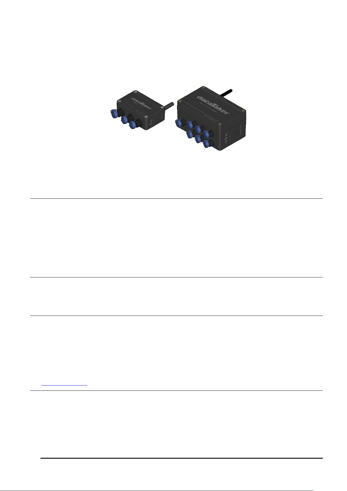
Part A – The DT90
Figure 1: dataTaker DT90N (left); DT90L (right)
DT90 Concepts
What is the DT90?
The DT90L and DT90N dataloggers, are compact all-in-one monitoring modules, designed specifically for remote
measurements, where emphasis is on low power, small size and ease of deployment. Having an analogue 16-bit channel
resolution and digital counters with SDI-12 / MODBUS RTU support it makes it possible to connect various sensors in the
field with minimum time.
Simple connectivity via USB on-site makes it easy to configure and test the deployed monitoring module. Remote
configuration gives the possibility to tune the system to arising needs. Variable sampling and transmission schedules are
possible to set up. The whole design is made to keep it small, simple and effective, meaning; low maintenance, long
uninterrupted working time and money saved!
The DT90 Product Family
The DT90 product family includes the following models:
The DT90L is a low cost, low power Compact variant of data logger
The DT90N is a Nano variant which is smaller model of DT90
DT90-Friendly Software
DT90 Configuration is a desktop based application for programming and monitoring DT90 Series data loggers. This
Config software requires installation in your PC. It provides a totally simple interface to create and set channels, each
channel can have different reading rate.
DT90 Configuration has inbuilt chart to view historic data values and download data. It also possible to trigger
instantaneous measurement.
All software is provided on the CD supplied with your DT90, and updates are available from the dataTaker website,
www.datataker.com (Support/ Downloads section).
About This Manual
This manual is intended for all users of the DT90. It describes:
How to connect sensors and other devices to the DT90's input and output channels.
How to program the DT90 to collect and return data as required.
How to manage the data that the DT90 collects.
UM-0090-B1E DT90 Range User Manual Page 6
RG

A Tour of the DT90's Interfaces
The DT90 have 2 interfaces with the outside world:
Communication/ Power and Sensor Interface
On the bottom part of DT90, there are nine round connectors – in which each connector has a dedicated interface:
Connector PC: External power and communication to PC interface
DT90L only:
Connector A1: 2 x voltage inputs or 2 x current inputs and 2 x 12V voltage excitation
Connector A2: 2 x voltage inputs or 2 x current inputs and 2 x 12V voltage excitation
Connector A3: 2 x RTD (PT100) inputs in 3 wire configuration or 2 x voltage inputs
Connector A4: 2 x RTD (PT100) inputs in 3 wire configuration or 2 x voltage inputs
DT90L and DT90N:
Connector D1: 3 x pulse inputs and 1 x 12V voltage excitation
Connector D2: 1 x SDI12 input and 1 x MODBUS input
Modem Interface
On the top part of DT90, there is coaxial screw connector for main antenna.
Getting Started
Power
DT90 models include an internal 3.6 V Li-ion battery which can power the logger if the main external supply is
interrupted. Several selection for main power are AC/DC adaptor, 12V/ 24V external battery or 9V/ 12V solar panel.
When power is connected and the lid is open, you could observe one LED below the left white terminal will start blinking.
Important: The DT90 is shipped with its internal battery disconnected. We recommend the battery is connected as soon as practical so
that it can charge from the mains adaptor or other external power source.
Connecting to a Host Computer
In order to program the DT90, it is generally necessary to connect it to a "host" computer. There is a cable for Connector
PC for USB connection to a PC. 3. The Windows "New Hardware Found" wizard will then run automatically (if required)
to complete the installation of the necessary drivers.
Launch DT90 Configuration to establish a connection.
Getting Help
This user manual is available in dataTaker website (www.datataker.com), including database of frequently asked
questions, code examples, sensor information, application notes, video tutorials and an online forum.
Designing Your Data Logging System
Data acquisition and data logging are orderly processes and should be undertaken in a systematic way. In order to
obtain effective information efficiently, do the following:
Identify the quantities to be measured.
Select the sensors, considering measurement range, accuracy, stability, ruggedness and cost.
Select the wiring configuration and data rates.
Determine sensor output scaling, that is, the relationship between sensor output voltage/ current and the actual
quantity.
Decide on the sample frequency – don't sample faster than you need to.
Decide on the method of data recovery and alarms.
The remainder of this manual will help you address these questions and then generate a suitable program for your DT90.
UM-0090-B1E DT90 Range User Manual Page 7
RG

Measurements
What can the DT90 Measure?
Analog
Using its analog inputs, the DT90 can directly measure the following:
DC voltage (50mV, 2.5V ranges)
4-20mA current loop
temperature (RTDs)
Digital
The DT90’s counter channels allow the measurement of:
pulse count (32 bit)
Serial
Various “smart sensors” can also be read:
SDI-12 based sensor networks
MODBUS RTU via RS485
UM-0090-B1E DT90 Range User Manual Page 8
RG
Part B – DT90 Configuration
What is DT90 Configuration?
DT90 Configuration is a desktop application to program DT90 series data logger, it will need to be installed on a PC.
This application will set channels, excitation output, data transfer and alarm. It is also possible to plot a chart on historical
data.
Connecting to DT90 Configuration
You can establish a connection to DT90 via USB cable.
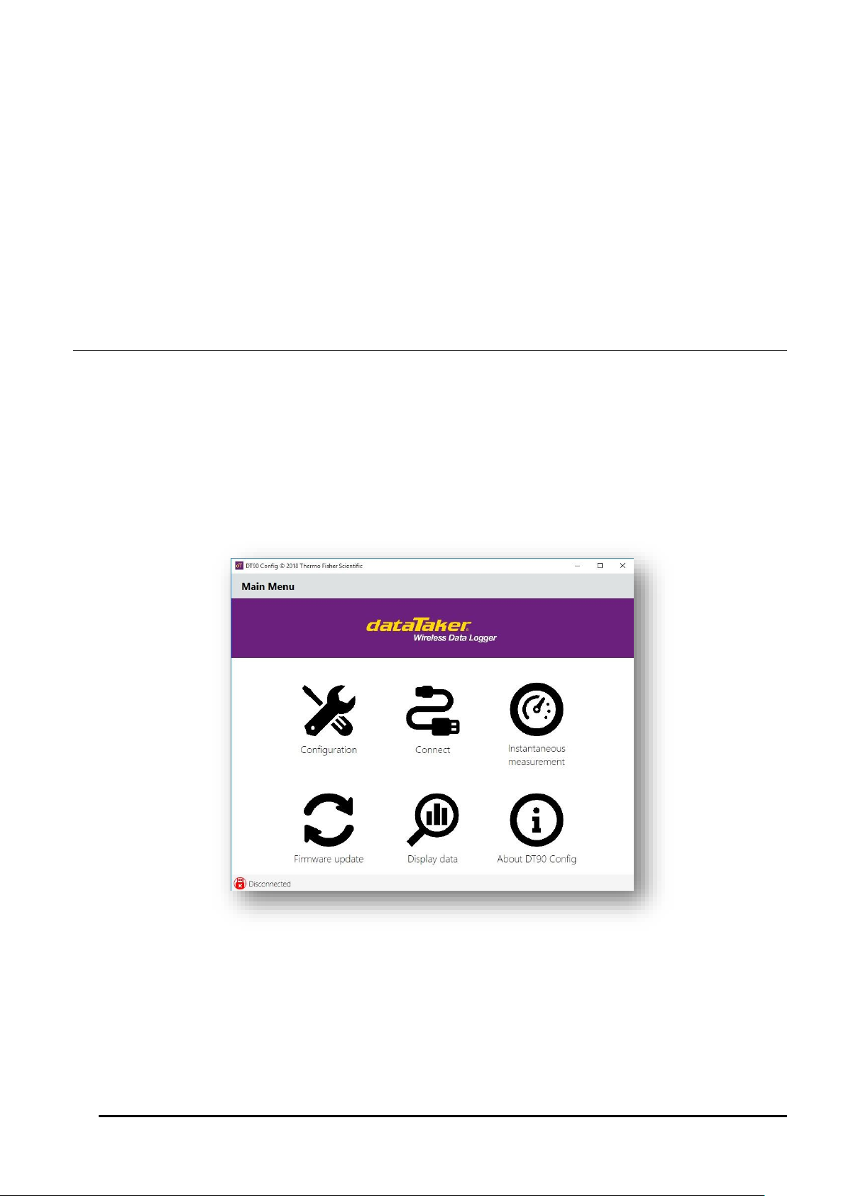
Main Menu
Page Description
The Main Menu of DT90 Configuration provides 6 options:
- Configuration – to configure the logger for reading signal from sensors, setting up data transmission and alarms.
- Connect – to establish connection to the logger
- Instantaneous Measurement – to get instantaneous reading from logger, download data, set up time and clear
logged data.
- Firmware Update – to update firmware
- Display Data – to display downloaded data
- About DT90 Configuration – to display software version
Figure 2: Main Menu Windows
UM-0090-B1E DT90 Range User Manual Page 9
RG
13
channels
Date
Time
Zone
Empty1
Empty2
Empty3
…
Empty12
Empty13
26
channels
Date
Time
Zone
Empty1
Empty2
Empty3
…
Empty25
Empty26
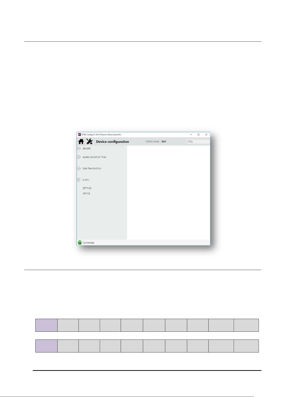
Configuration
Page Description
Configuration menu provides simple and intuitive access to the logger’s operation, Select Configuration option from
the main menu to access the configuration window.
Configuration windows comprises the following elements:
- Properties Pane on the right hand side is used to display various setting depending on menu selection. User
can define these setting according to requirements.
- Menus on the left hand side are used to access each configuration setting. There are four menus: Sensors,
Global Sensor Settings, Data Transmission and Alarm. Clicking on a menu will reveal menu items and each
item selection would be displayed in the properties pane.
- The banner area along the top screen contains one Home button which provides a link back to Main Menu and
two information tags: Station Name and Logger Type.
- The bottom of the screen displays Connection Status to the logger.
Figure 3: Configuration Windows
Sensors
Sensors menu is used to create measurement channel based on sensor’s output signal. There are 2 possible “maximum
number” of available channels in a logger unit depending on firmware version, 13 channels (factory default) and 26
channels (optional).
The above selection will determine the number of maximum data point to be recorded in FLASH memory, with 16 MB in
size the logger can hold 260,000 data points (for 13 channels) or 130,000 data points (for 26 channels).
Table 1: Logger memory mapping
UM-0090-B1E DT90 Range User Manual Page 10
RG
 Loading...