

Page 1

CTS™ Rotea™ Counterflow Centrifugation
System
USER GUIDE
Catalog Number A44769
Publication Number MAN0018908
Revision B.0
For Research Use or Manufacturing of Cell, Gene, or Tissue- Based
Products.
Page 2
Life Technologies Holdings Pte Ltd | Block 33 | Marsiling Industrial Estate Road 3 | #07-06, Singapore 739256
For descriptions of symbols on product labels or product documents, go to thermofisher.com/symbols-definition.
The information in this guide is subject to change without notice.
DISCLAIMER: TO THE EXTENT ALLOWED BY LAW, THERMO FISHER SCIENTIFIC INC. AND/OR ITS AFFILIATE(S) WILL NOT BE
LIABLE FOR SPECIAL, INCIDENTAL, INDIRECT, PUNITIVE, MULTIPLE, OR CONSEQUENTIAL DAMAGES IN CONNECTION WITH OR
ARISING FROM THIS DOCUMENT, INCLUDING YOUR USE OF IT.
The CTS™ Rotea™ Counterflow Centrifugation System is for use in further manufacturing applications only and not for fill and finish
applications. Drug manufacturers are responsible for ensuring the purity, potency, safety and identity of finished drug products and for
obtaining the appropriate regulatory approvals.
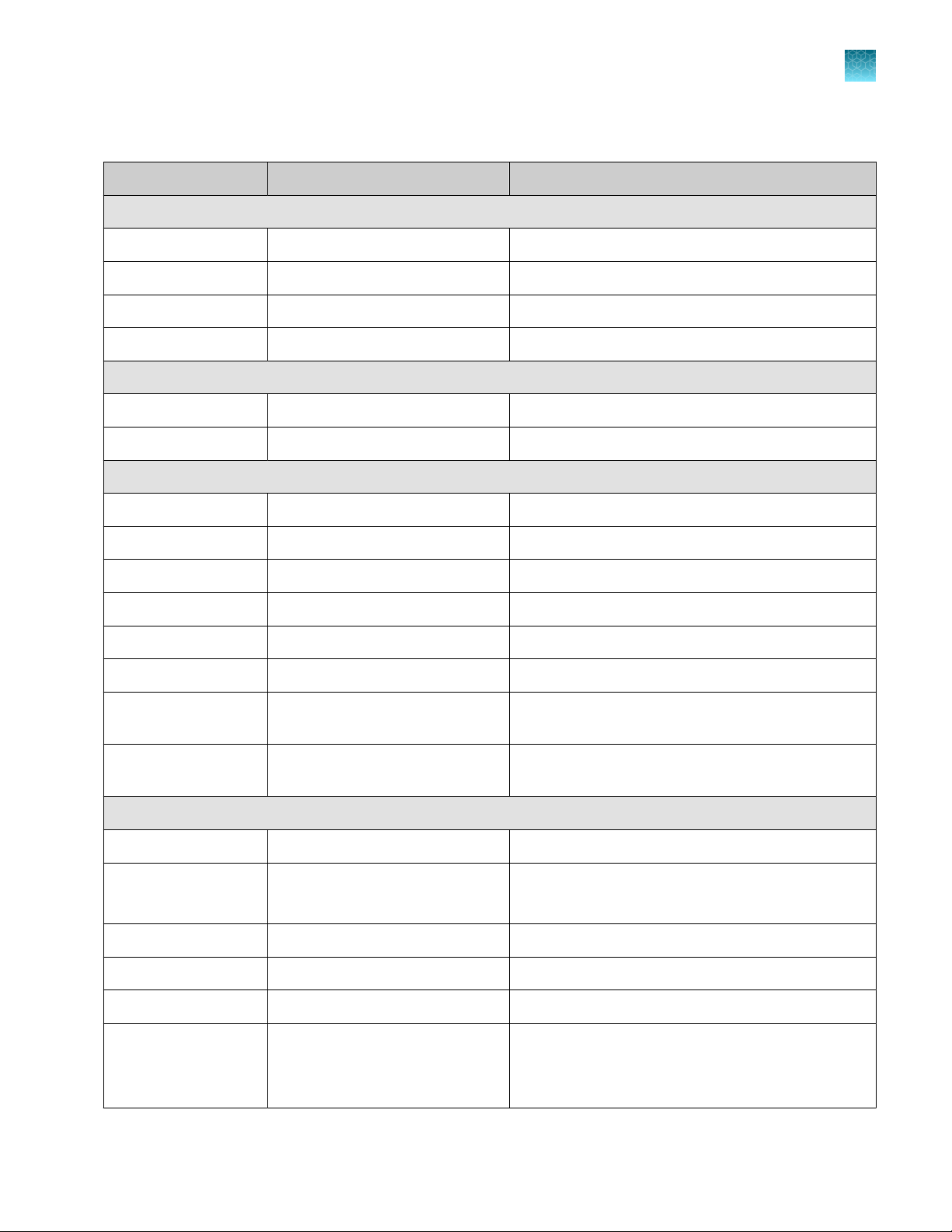
Revision history: Pub. No. MAN0018908
Revision Date Description
B.0 02 December 2020 Minor change to CTS™ Rotea™ Counterflow Centrifugation System
A.0 20 October 2020 New document. User guide for new workflow.
specific disclaimer statement.
Important Licensing Information: This product may be covered by one or more Limited Use Label Licenses. By use of this product,
you accept the terms and conditions of all applicable Limited Use Label Licenses.
TRADEMARKS: All trademarks are the property of Thermo Fisher Scientific and its subsidiaries unless otherwise specified.
©2020 Thermo Fisher Scientific Inc. All rights reserved.
Page 3

Contents
■
CHAPTER 1 Product information .................................................. 7
Product description ............................................................. 7
Features ....................................................................... 7
Contents ....................................................................... 7
System overview ................................................................ 8
Instrument description ....................................................... 8
Instrument dimensions ..................................................... 10
Working space ............................................................ 10
Instrument weight ......................................................... 10
Instrument properties ...................................................... 11
Push button controls ....................................................... 13
CTS™ Rotea™ Single-Use Kit schematic ...................................... 14
Wetted components ....................................................... 15
Allowed chemicals for wetted surfaces ....................................... 15
■
CHAPTER 2 Installation and setup ............................................... 16
Packaging contents ............................................................ 16
Instrument installation .......................................................... 16
Power instrument “On” ......................................................... 18
Power instrument “O” ......................................................... 19
Installation .................................................................... 20
First time setup ................................................................ 24
Download protocols ............................................................ 27
Create protocols ........................................................... 27
Load a protocol ........................................................... 27
Rotea™ GUI dashboard ..................................................... 31
User Management ......................................................... 32
Uninstall ...................................................................... 37
Logging ....................................................................... 38
™
Rotea™ Counterflow Centrifugation System User Guide
CTS
3
Page 4

Contents
■
CHAPTER 3 Basic instrument operation ........................................ 41
Open the door ................................................................. 41
Kit preparation, loading and removal ............................................. 43
Kit configuration ........................................................... 43
Pre-assembly of processing kit .............................................. 45
Connecting vessels, bags and reagents ...................................... 46
Bubble Trap ............................................................... 47
Kit installation ............................................................. 48
Initiate a protocol .......................................................... 54
Run a protocol ................................................................. 61
Rotea™ GUI navigation and instrument operation .............................. 61
Error messages ............................................................ 67
Kit removal .................................................................... 69
Aseptic disconnection of the kit components ...................................... 74
System settings ................................................................ 75
Instrument firmware ........................................................ 75
OPC-UA .................................................................. 80
Settings .................................................................. 81
Licenses .................................................................. 82
Calibration .................................................................... 83
■
CHAPTER 4 OPC-UA interface ................................................... 87
Introduction ................................................................... 87
Definitions .................................................................... 87
Scope of system ............................................................... 88
Instrument hardware configuration ........................................... 88
Single-Use Kit ............................................................. 88
Protocol file ............................................................... 89
Protocol metadata ......................................................... 89
MES interface ................................................................. 89
Background ............................................................... 89
Electronic communications ................................................. 90
Communications protocol .................................................. 90
MES – Commands and reports overview .......................................... 91
Enable OPC-UA ........................................................... 92
Log in to instrument ........................................................ 92
Load protocol ............................................................. 92
Load kit .................................................................. 93
Transfer metadata ......................................................... 93
Initialize protocol on to instrument ........................................... 93
Start/Stop/Pause/Resume protocol .......................................... 93
Instrument run status ....................................................... 94
4
CTS™ Rotea™ Counterflow Centrifugation System User Guide
Page 5

MES batch history data ..................................................... 94
Alarm recovery tools ....................................................... 95
OPC-UA interface .............................................................. 96
Commands OPC-UA to Rotea™ application ................................... 96
Reports Rotea™ application to OPC-UA ...................................... 97
Use case sequence diagrams .................................................. 104
MES run a protocol ....................................................... 104
Protocol with parametric data .............................................. 105
MES drives Rotea in response to external systems ........................... 106
MES drives steps within protocol ........................................... 106
MES manage error recovery events with admin user .......................... 107
Use list file to load protocol ............................................... 108
■
CHAPTER 5 Maintenance ....................................................... 110
User maintenance schedule .................................................... 110
Instrument cleaning ........................................................... 110
Inspect casing ................................................................ 110
Open the door without power .................................................. 111
Power and fuses .............................................................. 112
Power supply ............................................................ 112
Fuses ................................................................... 112
Contents
■
CHAPTER 6 Troubleshooting ................................................... 113
■
CHAPTER 7 Compliance ........................................................ 115
■
CHAPTER 8 Safety instructions ................................................ 116
Labels ....................................................................... 116
Emergency procedures ........................................................ 116
Instrument emergency stop events ......................................... 116
Emergency shut down .................................................... 117
Restart after shut down ................................................... 117
Protocol recovery process ................................................. 118
Warnings and precautions ..................................................... 119
Warnings ................................................................ 119
Cautions ................................................................ 120
CTS™ Rotea™ Counterflow Centrifugation System User Guide
5
Page 6

Contents
■
APPENDIX A Safety .............................................................. 121
Symbols on this instrument .................................................... 121
Standard safety symbols .................................................. 122
Control and connection symbols ........................................... 122
Conformity symbols ...................................................... 122
Safety information for instruments not manufactured by Thermo Fisher Scientific ..... 124
Instrument safety ............................................................. 124
General ................................................................. 124
Physical injury ............................................................ 125
Electrical safety .......................................................... 125
Cleaning and decontamination ............................................. 126
Safety and electromagnetic compatibility (EMC) standards ......................... 126
Safety standards ......................................................... 126
EMC standards ........................................................... 127
Environmental design standards ............................................ 127
Chemical safety .............................................................. 128
Biological hazard safety ....................................................... 129
■
APPENDIX B Documentation and support .................................... 130
Customer and technical support ................................................ 130
Limited product warranty ...................................................... 130
6
CTS™ Rotea™ Counterflow Centrifugation System User Guide
Page 7

1
IMPORTANT! Before using this product, read and understand the information in the “Safety” appendix
in this document.
Product description
The CTS™ Rotea™ Counterflow Centrifugation System is an automated, closed-flow benchtop
instrument that can perform a wide variety of cell processing steps across dierent cell types.
The CTS™ Rotea™ Single-Use Kit is specifically designed for a range of cell processing applications
such as separation, isolation, buer exchange, wash and concentrate. Each kit has 8 input/output
sterile weldable tubes, counterflow centrifuge and Carrier Frame for unparalleled setup flexibility.
The CTS™ Rotea™ Software is user-programmable and allows users to save, create, and modify
protocols depending on the application. The system's open design and integrated camera allows users
to visualize cells in real-time to more easily optimize protocols.
Product information
Features
CTS™ Rotea™ Counterflow Centrifugation System easily fits into existing workflows, from research to
commercial manufacturing.
•
Integrated camera provides real-time sample visualization
•
Patented technology that can process up to 20 L of starting volume to as little as 5 mL of output
volume
•
Gentle fluidized bed results in unmatched cell recovery and viability
•
Seamlessly transition from process development to GMP manufacturing on the same system.
Contents
Table 1 CTS™ Rotea™ Counterflow Centrifugation System (Cat. No. A44769)
Contents
CTS™ Rotea™ Centrifuge 1 ea
CTS™ Rotea™ Single-Use Kit Available separately
Protocol Development Application 1 ea
Amount
Dell™ 2-in-1 laptop for operation/programming 1 ea
CTS™ Rotea™ Counterflow Centrifugation System User Guide
7
Page 8
2
1
3
4
5
6
7
8
9
10
11
12
13
14
15
16
17
18
Chapter 1 Product information
1
System overview
System overview
Instrument description
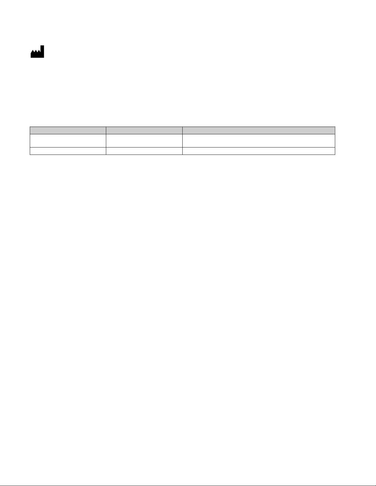
Figure 1 Instrument – Front View
Instrument Door
1
Pinch Valves (J & K)
2
Kit Location Button
3
2D Barcode Reader
4
CFC Chamber Detector
5
CFC Chamber Carrier
6
Camera
7
Moisture Sensor
8
Pushbutton Controls
9
8
Optical Density Sensor & Pressure Sensor (P1)
10
Peristaltic Pump
11
Pump Clamp Arm
12
Pinch Valve (H)
13
Kit Location Button & Pressure Sensor (P2)
14
Door Latch
15
Pinch Valves (A, B, C, D, E, F, & G)
16
Bubble Sensors
17
Hanger Posts
18
CTS™ Rotea™ Counterflow Centrifugation System User Guide
Page 9
8
7
6
5111
1
432
Chapter 1 Product information
System overview
1
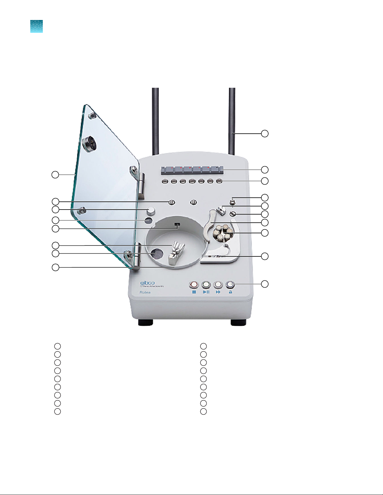
Figure 2 Instrument – Rear View
Power Switch
1
Mains Connector
2
CAN bus (2 o)
3
Ethernet (RJ-45)
4
USB-C
5
Bag Hooks
6
Hanger Post
7
Hanger Post Adjustment
8
CTS™ Rotea™ Counterflow Centrifugation System User Guide
9
Page 10
1
Chapter 1
System overview
Product information
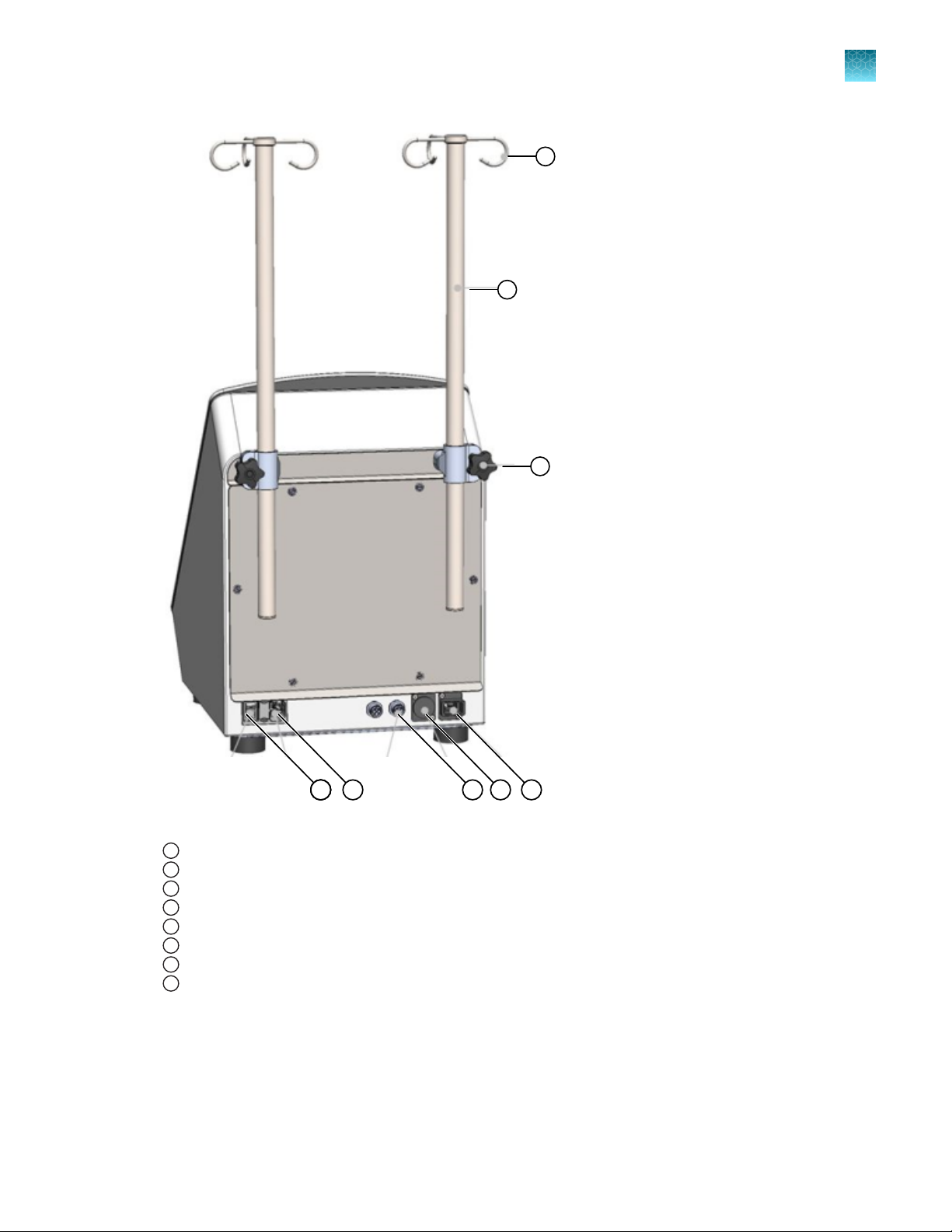
Instrument dimensions
Working space
The Rotea™ instrument is designed for bench top use and requires a working space of approximately
Height: 30” (76 cm), Width: 25” (63.5 cm), Depth: 20” (50.8 cm).
Note: The 2‑in‑1 laptop is connected via a USB-C cable and hence can be located in a range of
positions. The width dimension of 25” assumes that the laptop is located on the bench beside the
instrument.
Instrument weight
The Rotea™ instrument weighs 44 lbs (20 kg) with hanger posts installed.
10
CTS™ Rotea™ Counterflow Centrifugation System User Guide
Page 11
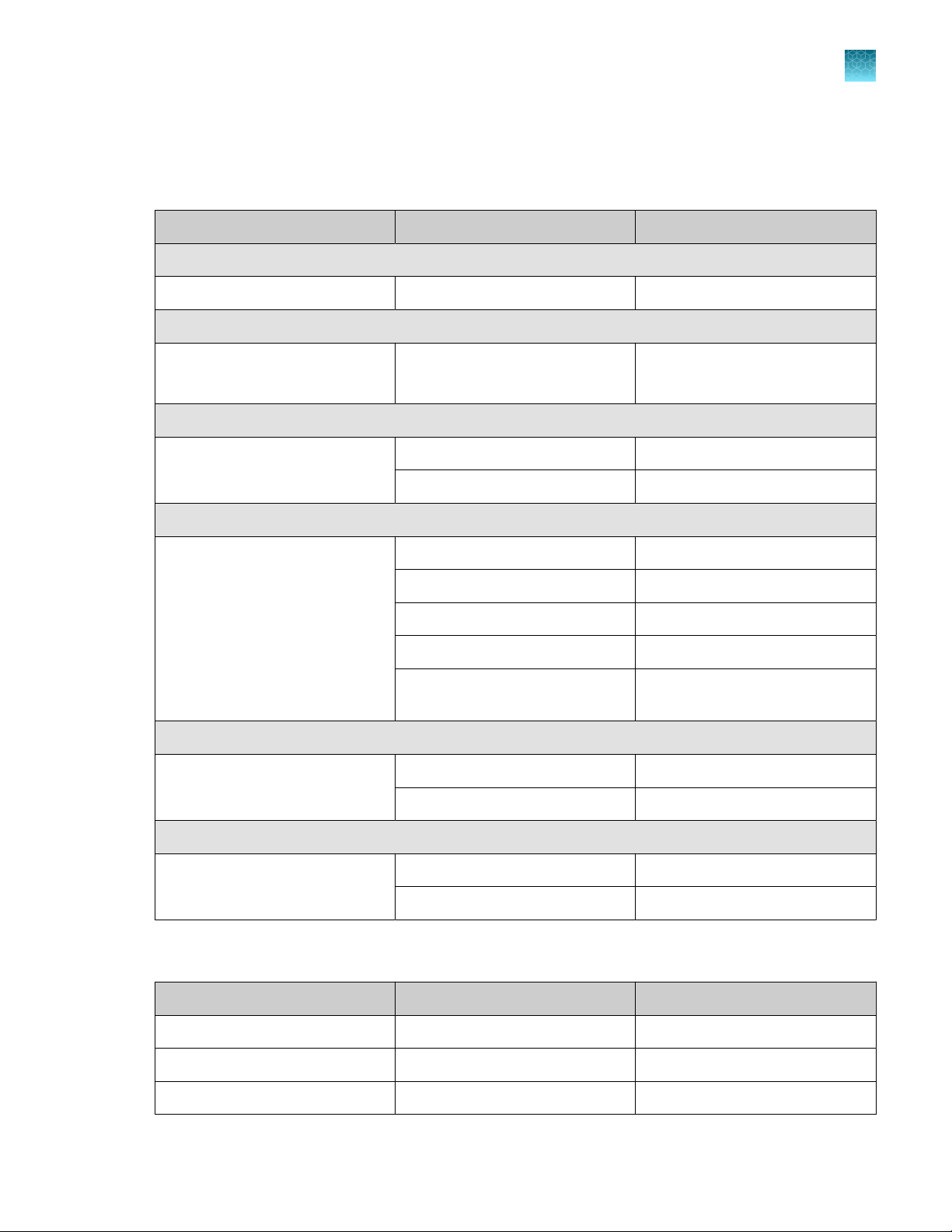
Instrument properties
Chapter 1 Product information
System overview
1
Category
Electrical
Sound level
Environmental ranges
Property Value
Supply voltage 100–240 V AC ±10%, 50/60 Hz
Phases Single
Maximum Rated Input Current 5 A
Fuses 2 x 5 A
Maximum sound level 70 dBA (measured 1 m from instrument)
Typical sound level 65 dBA (measured 1 m from instrument)
Ambient temperature 15℃ to 30℃
Transport temperature 0℃ to 45℃
Storage temperature 15℃ to 30℃
Maximum relative humidity 80% (non-condensing)
Operating limits
Altitude (max.) 2000 m
Indoor use only —
Not intended for use in a wet
location
Intended for use in Pollution
degree 2 environment
Centrifuge speed 0 to 3000 × g (7000 rpm)
Flow rate Standard: 5 to 110 mL/min (LS19)
Hi-Flow: 30 to 160 mL/min (LS16 tube)
System pressure 100 kPa
Liquid temperature 4℃ to 38℃
Fluid density 1.0 to 1.1 g/mL
Minimum working volume Approx. 50 mL
Note: Smaller volumes of input material can be
diluted to enable processing
—
—
CTS™ Rotea™ Counterflow Centrifugation System User Guide
11
Page 12
Chapter 1 Product information
1
System overview
(continued)
Category
CAN bus connection
Property Value
Minimum concentrate recovery
volume
Centrifuge chamber volume 10 mL chamber containing up to 4 × 10⁹ cells (cell
type and operating parameters dependent).
Note: Centrifuge chamber can be filled multiple
times to process larger batches.
Maximum bag weight per pole 4.4 lb (2 kg)
Output concentration Up to 300 × 106 cells/mL (cell type and operating
parameters dependent)
Purpose For connection and control of external devices
Connector TE Connectivity T4111402051-000 M12 Plug
Connections Pin 1 - VCC CAN - +5V out
Pin 2 - CAN-H - Dominant High
Pin 3 - CAN-L - Dominant Low
5 mL (subject to protocol optimization)
Pin 4 - GND - Ground
Pin 5 - GND - Shield, optional
12
CTS™ Rotea™ Counterflow Centrifugation System User Guide
Page 13
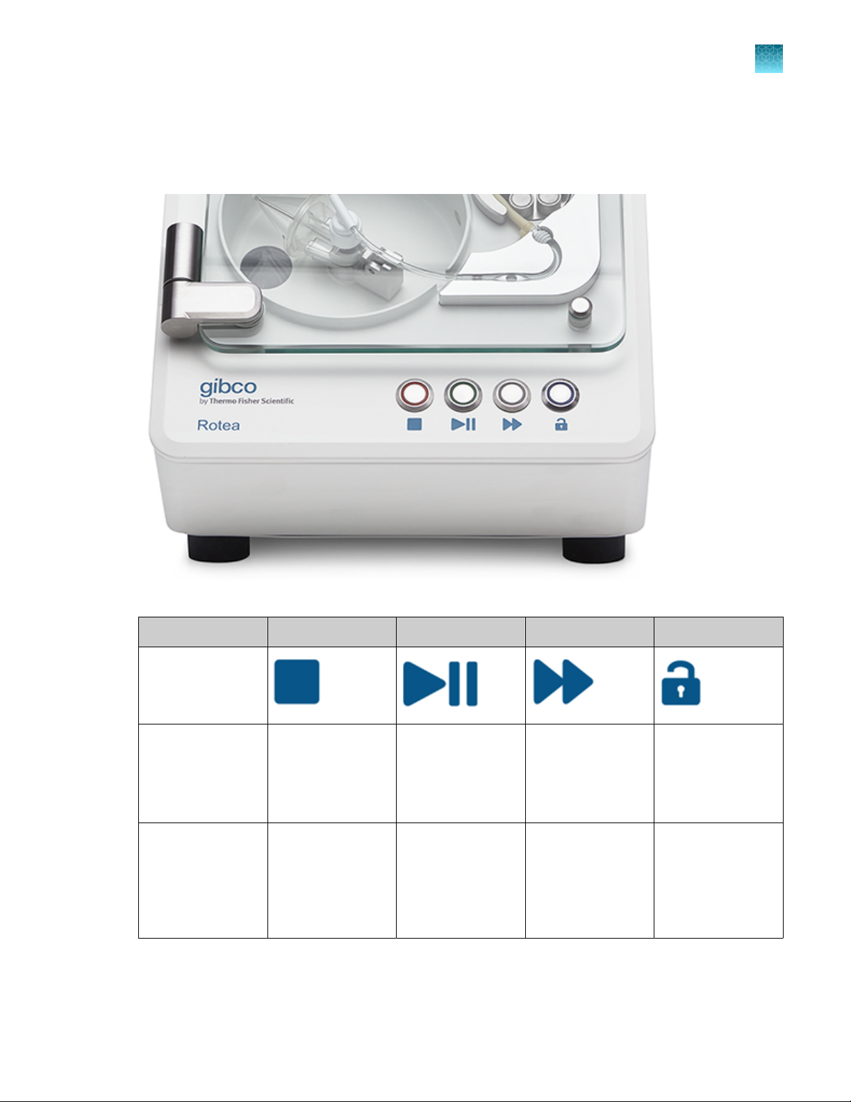
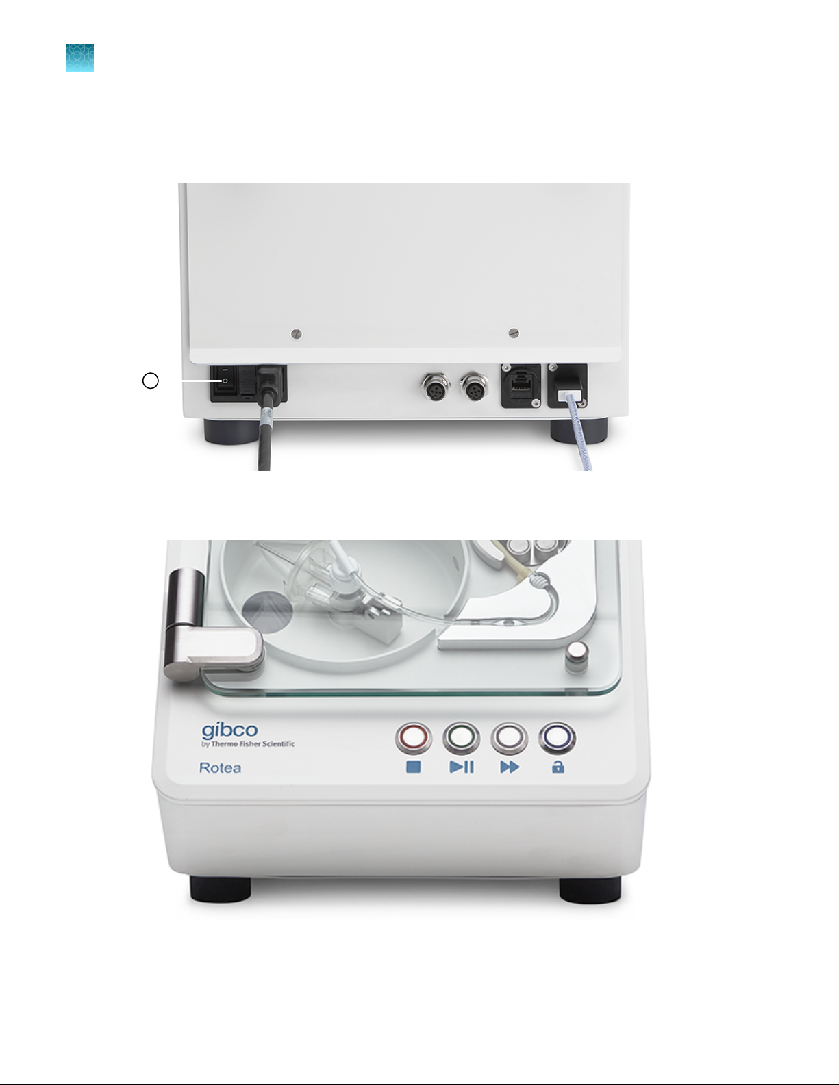
Push button controls
Once a protocol has been loaded and confirmed, the Rotea™ instrument can be operated almost
entirely from the push buttons on the front of the instrument.
Chapter 1 Product information
System overview
1
Figure 3 Instrument push button controls
Light
Push button
operation
Solid Push button to stop
Flashing Instrument has
STOP START/PAUSE ADVANCE DOOR UNLOCK
the instrument and
the current protocol
stopped due to
an alarm condition.
User intervention is
required.
Push button to start
the Protocol, pause
the current step in
the protocol or re-
start a paused step
Instrument is in a
paused condition.
Pressing allows
the instrument to
continue the current
step of the protocol.
Push button to
advance to the next
step in the protocol
Button can be
pushed, advancing
to the next step of
the protocol
Push button to
unlock the door
N/A
CTS™ Rotea™ Counterflow Centrifugation System User Guide
13
Page 14
6
3
5
1
2
4
7
8
9
10
11
12
Chapter 1 Product information
1
System overview
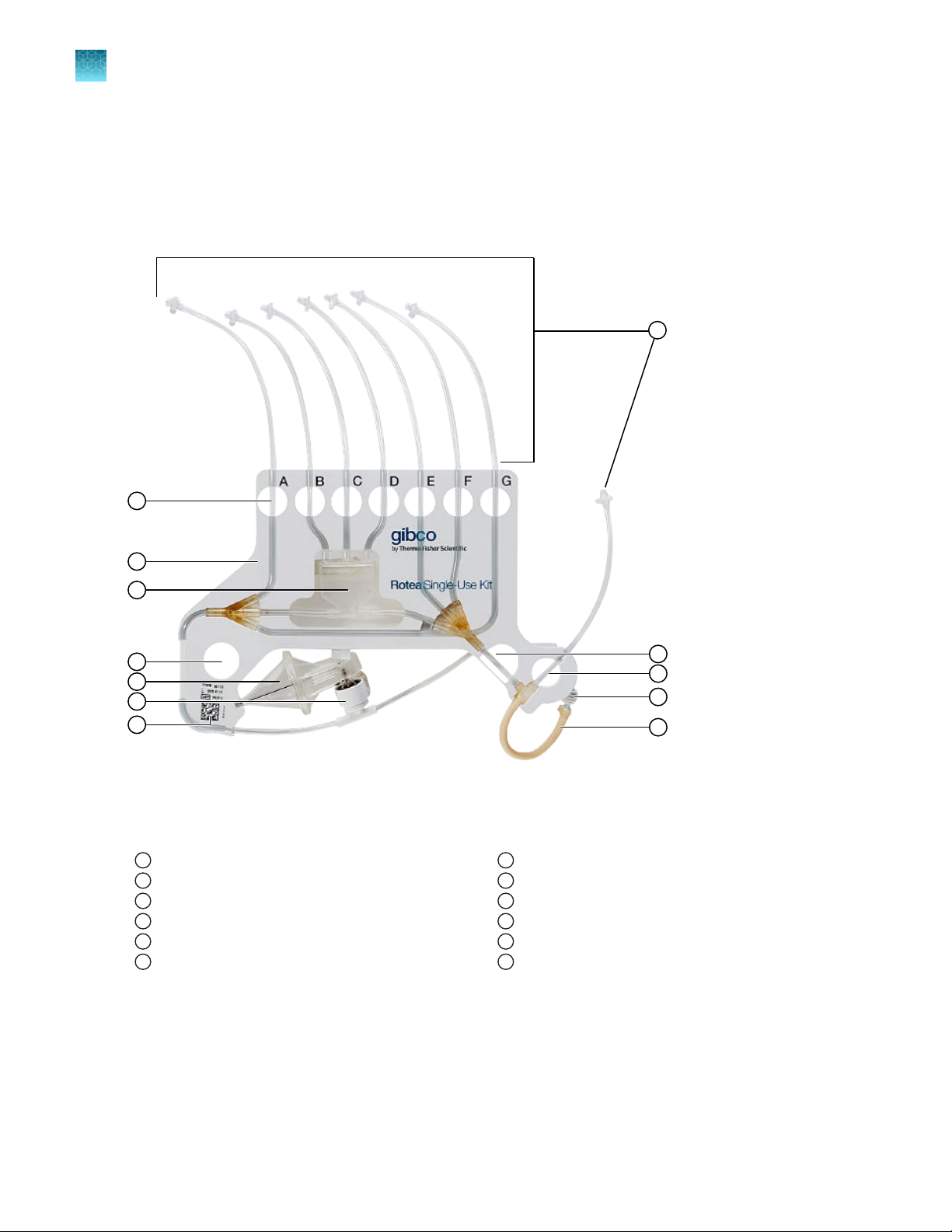
CTS™ Rotea™ Single-Use Kit schematic
The CTS™ Rotea™ Single-Use Kit enables users to configure kits to suit dierent protocols by adding
input and output vessels. Unused fluid lines are simply left sealed o.
Figure 4 CTS™ Rotea™ Single-Use Kit
Valve Hole & Tube ID
1
Carrier Frame
2
Bubble Trap
3
Location Hole
4
CFC Chamber
5
Rotary Coupling
6
14
2D Barcode
7
Pump Tubing
8
Tube Retainer
9
Valve H Hole
10
Location Hole
11
Kit Tubing (Input and Output)
12
CTS™ Rotea™ Counterflow Centrifugation System User Guide
Page 15
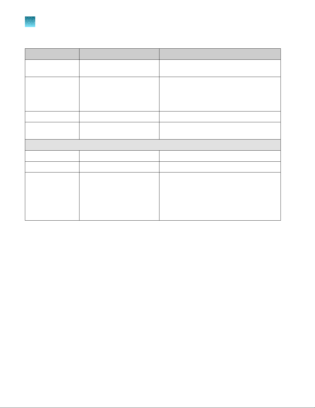
Wetted components
The materials used in the manufacturing of the CTS™ Rotea™ Single-Use Kit have been chosen for their
biological and chemical compatibility.
Component Description Material
Pump tubing
Kit tubing
Chapter 1 Product information
System overview
Pump tube Bioprene
1
CFC ChamberC
Rotary Coupling
Bubble Trap
0.160” OD, 0.116” ID
(4 mm OD, 3 mm ID)
Base Tritan MX711
Cone Tritan MX711
O-Rings EPDM, 70 DURO, FDA compliant
Cannular 316 SS
Cap Tritan MX711
Body Tritan MX711
Bush & Collar Ketron LSG Peek Classix, USP
Base Tritan MX711
Cap Tritan MX711
DEHP-FREE PVC
Class VI
Fittings
Triple Y Connector PVC
Barbed T-Connector Polyproylene
Allowed chemicals for wetted surfaces
Chemical
WFI 100% 5 minutes
Ethanol in water 50% 5 minutes
Culture media 100% 5 minutes
CTS™ Rotea™ Counterflow Centrifugation System User Guide
Concentration Maximum exposure time
15
Page 16
2
Packaging contents
•
Rotea™ instrument
•
Hanger posts (2 o)
•
Mains plug IEC cables (USA/EUROPE/AUSTRALIA)
•
Pre-fitted mains fuses (2 x 5A)
•
USB-C (male) to USB-C (female)
•
Dell™ 2‑in‑1 laptop tablet (this will be in a separate carton)
Instrument installation
•
Remove outer packaging
•
Prepare bench space to receive Rotea™ instrument unit (see “Working space” on page 10) ensuring
that there is easy access to the “On/O” switch and mains IEC connector at the rear of the
instrument
Installation and setup
CAUTION! The Rotea
it is the user’s responsibility to ensure all safety hazards and functional risks are addressed including
adequately supporting the weight of the instrument and having sucient wheel span so that both the
trolley and instrument are stable.
•
Ensure that the bench is stable and level to within ±0.4" (10 mm)
•
Position the instrument on the bench with a minimum of 4" (10 m) between the rubber feet and the
edges of the bench
CAUTION! The Rotea
appropriate care and seek assistance if necessary when lifting or moving the instrument. Lift the
instrument, holding between the rubber feet on the bottom of the instrument.
CAUTION! Do not position the instrument is such a way that it would make it dicult to disconnect
the power cord from the power inlet.
CAUTION! If using an alternate mains cable, ensure it is rated for at least 10A.
™
instrument should be installed on a stable bench. If a mobile set up is used,
™
instrument weighs 40 lbs (18 kg) excluding hanger bag posts. Use
16
CTS™ Rotea™ Counterflow Centrifugation System User Guide
Page 17
1
2
Chapter 2
Note: Suitable means of protective earthing are provided for this device
Installation and setup
Instrument installation
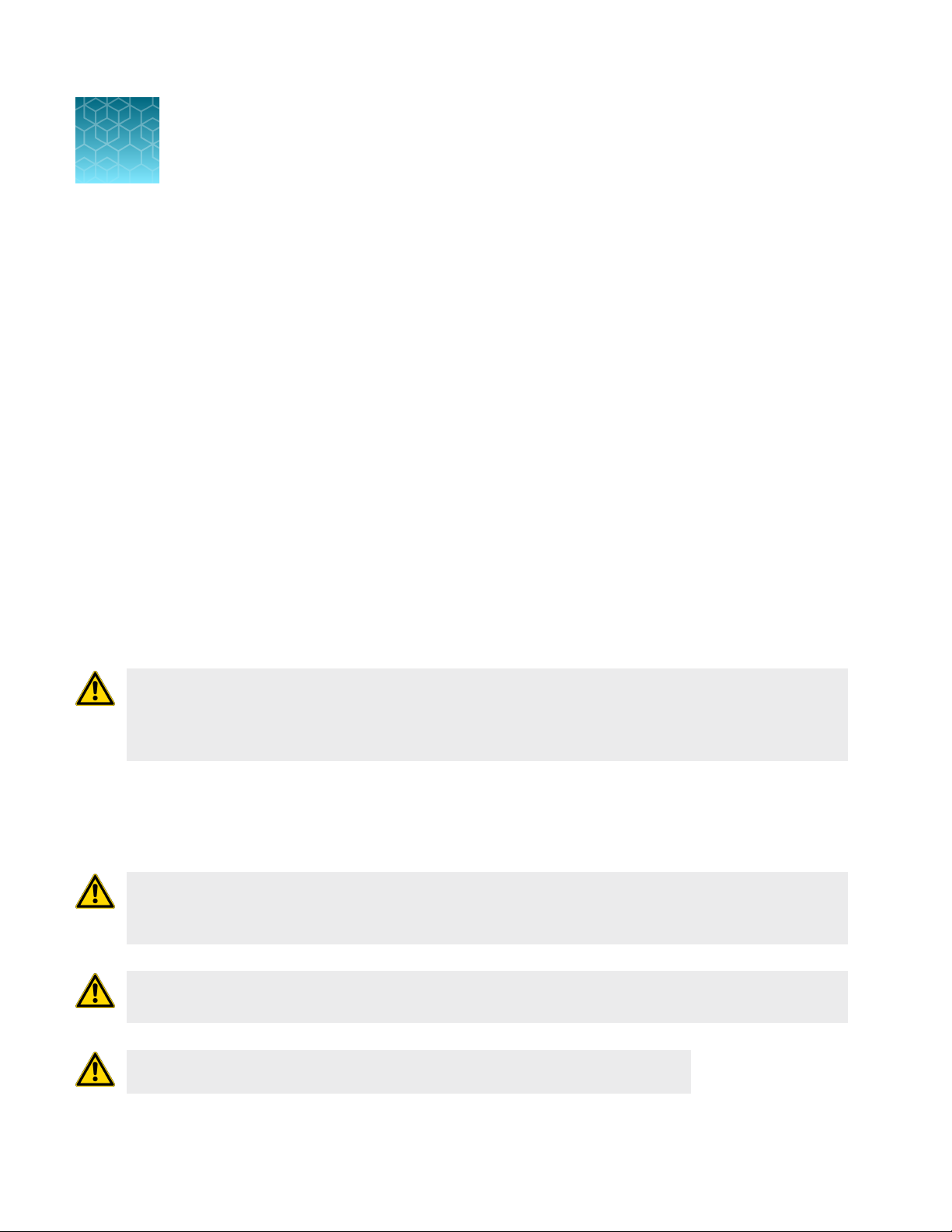
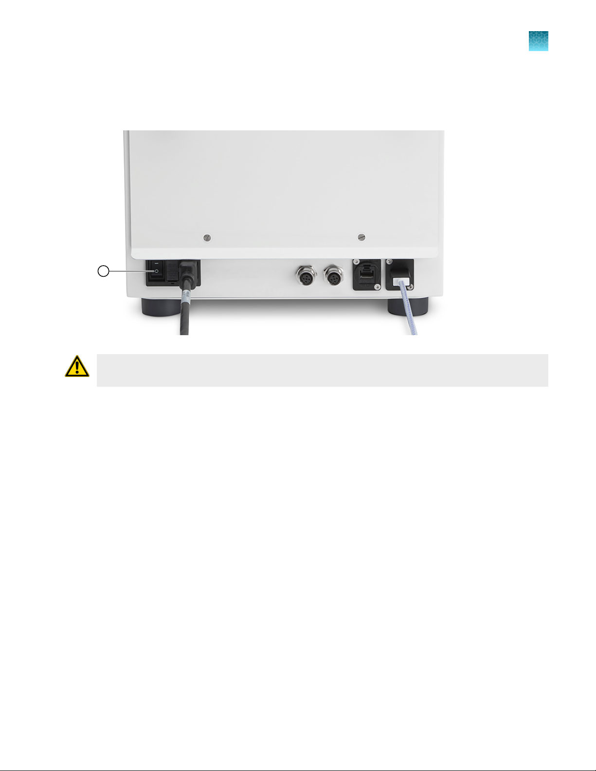
2
Figure 5 Back view of instrument
Mains IEC connector
1
USB-C port
2
1.
Connect mains IEC connector.
2.
Plug mains into power GPO
3.
Connect the laptop to USB-C port on the instrument using the USB-C cable.
4.
Insert 2 o bag hanger posts, adjust height to suit Kit and turn nut clockwise to secure in place.
5.
Adjust the instrument position on the bench where it is required.
CTS™ Rotea™ Counterflow Centrifugation System User Guide
17
Page 18
1
Chapter 2 Installation and setup
2
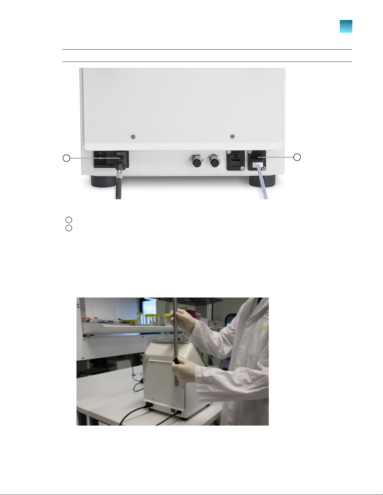
Power instrument “On”
Power instrument “On”
1.
Switch on using the mains IEC switch at the rear of the instrument.
2.
The instrument button lights will sequence as the instrument powers up. If the door is closed, the
instrument will automatically check if a Single-Use Kit is installed.
18
CTS™ Rotea™ Counterflow Centrifugation System User Guide
Page 19
Power instrument “O”
1
Switch o the instrument using the mains IEC switch or mains power.
Chapter 2 Installation and setup
Power instrument “O”
2
CAUTION! There is no automatic recovery procedure. If a loss of power event has occurred see
“Restart after shut down” on page 117.
CTS™ Rotea™ Counterflow Centrifugation System User Guide
19
Page 20
Chapter 2 Installation and setup
2
Installation
Installation
The Dell™ 2‑in‑1 laptop will be pre-installed with Windows™ OS. The latest CTS™ Rotea™ Graphical User
Interface (GUI) software will need to be installed onto the Dell™ 2‑in‑1 laptop provided. New releases of
the Rotea™ GUI software will be available for download from thermofisher.com.
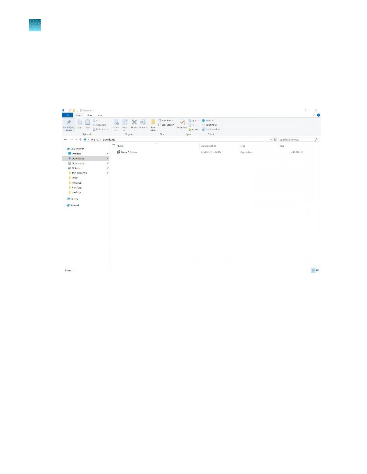
1.
Download the Rotea-X.X.X.exe installer.
20
CTS™ Rotea™ Counterflow Centrifugation System User Guide
Page 21
Chapter 2
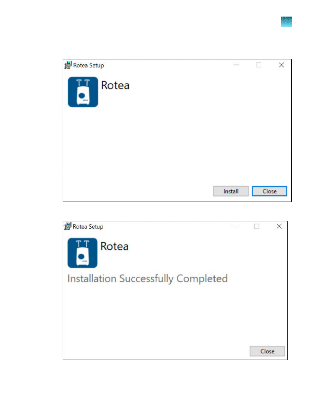
2.
Run the Rotea-X.X.X.exe installer. Click Install. The application will be installed in C:\Program
Files (x86)\Rotea\.
Installation and setup
Installation
2
3.
Click Close to finish the app installation.
4.
Power on the Rotea™ instrument (with the switch on the back) and plug it into the laptop.
CTS™ Rotea™ Counterflow Centrifugation System User Guide
21
Page 22
Chapter 2 Installation and setup
2
Installation
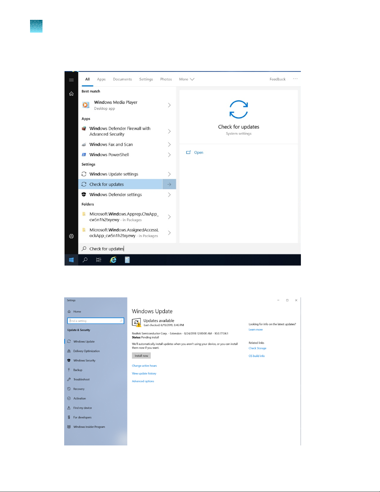
5.
The next step is to update Windows™ software. Make sure the laptop is connected to the local wifi
network. This can be done by opening the start menu and searching for Check for updates.
6.
Click Check for updates, Install now and restart the laptop as required. This process may need
to be repeated multiple times until Windows™ software is completely up to date.
22
CTS™ Rotea™ Counterflow Centrifugation System User Guide
Page 23
Chapter 2
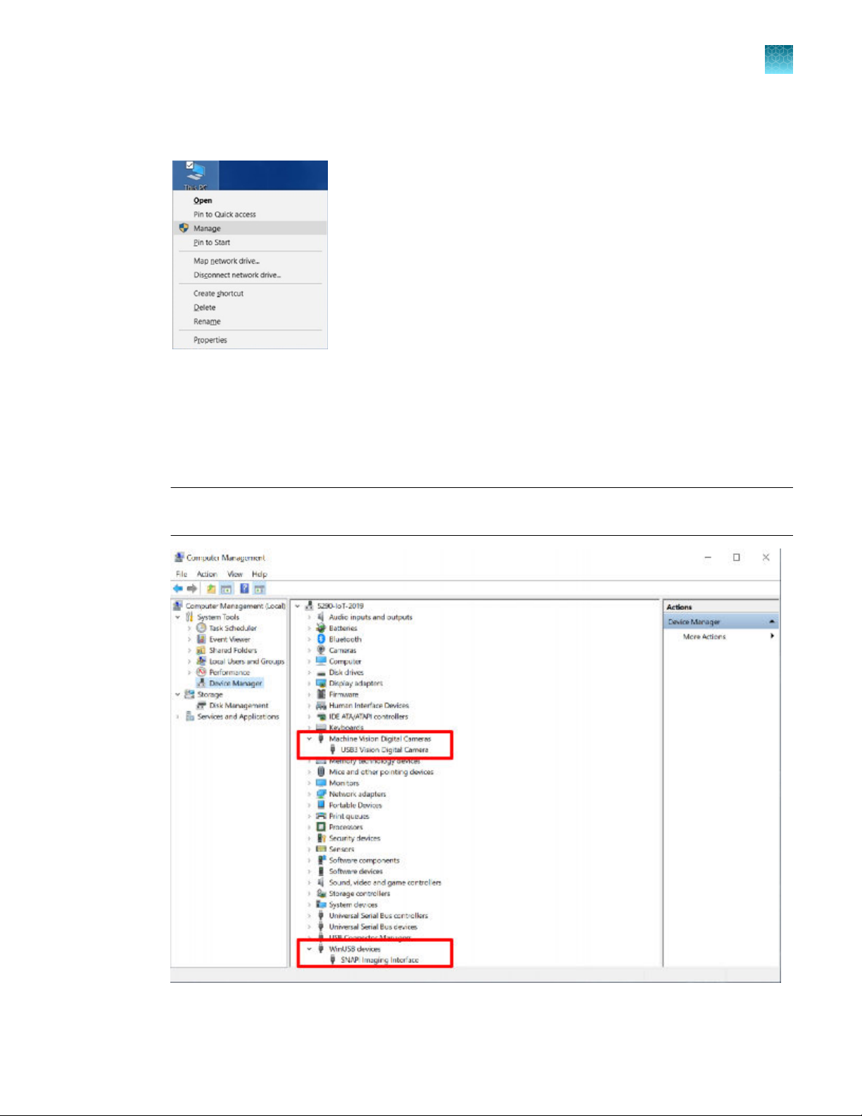
7.
Check if Windows Update installed the required USB device drivers. Right click on This PC on the
desktop and open Manage.
8.
Ensure the USB devices are detected correctly. Check that the devices highlighted in figure can be
seen:
•
USB Vision Digital Camera
•
USB Serial Port (COM X)
•
SNAPI Imaging Interface
Installation and setup
Installation
2
Note: If these devices are missing ensure the USB cable is plugged in, the Rotea™ instrument is
powered and on, that there are no more Windows™ software updates to complete.
9.
The installation is now complete. Move onto setting up the application for the first time.
CTS™ Rotea™ Counterflow Centrifugation System User Guide
23
Page 24
Chapter 2 Installation and setup
2
First time setup
First time setup
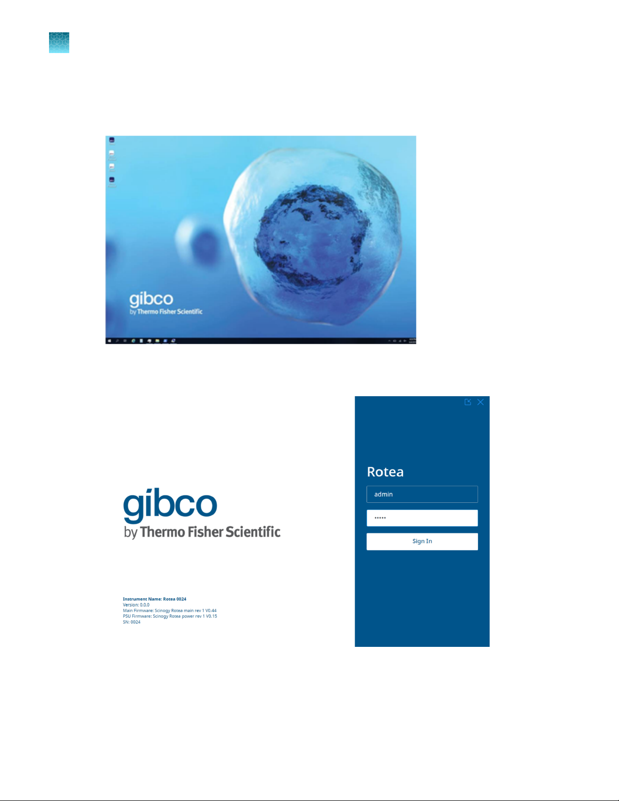
1.
Push the power button on the laptop to start Windows™ software.
2.
Run the Rotea™ application from the desktop or start menu. The application has a single admin
user with Username: admin, Password: admin on a fresh installation.
24
CTS™ Rotea™ Counterflow Centrifugation System User Guide
Page 25
Chapter 2 Installation and setup
First time setup
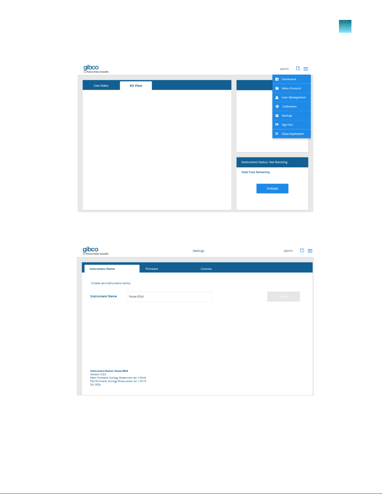
3.
The main navigation menu in the top right corner is used to get to all areas of the applications.
2
4.
Click the Settings in the navigation menu to set the instrument name. Edit the instrument name if
required.
CTS™ Rotea™ Counterflow Centrifugation System User Guide
25
Page 26
2
Chapter 2
First time setup
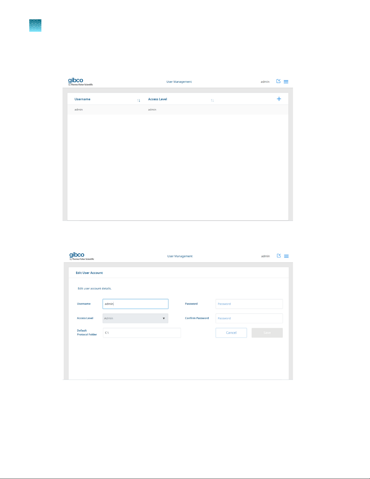
5.
Installation and setup
Click User Management in the navigation menu to change the admin username/password. This
page shows all the users configured for in the application. Click the admin user to change the
account details. New users can be added with the + button.
6.
Change the admin user account username, password and the default directory for this user to find
protocols. Click Save for any changes.
7.
The configuration is now complete.
26
CTS™ Rotea™ Counterflow Centrifugation System User Guide
Page 27
Download protocols
Create protocols
Protocols comprise a series of individual steps that are to be perfomed by the instrument. Triggers are
used to define when the instrument will move to the next step. A range of existing protocols can be
downloaded from the Thermo Fisher Scientific portal.
Users can also modify existing protocols or create entirely new protocols using the Rotea Protocol
App that can be installed on any Windows™ PC, laptop or tablet.
Protocols can be saved for future retrieval using the GUI.
The Rotea Protocol App can be accessed at any time by clicking on the icon on the desktop.
Chapter 2 Installation and setup
Download protocols
2
Load a protocol
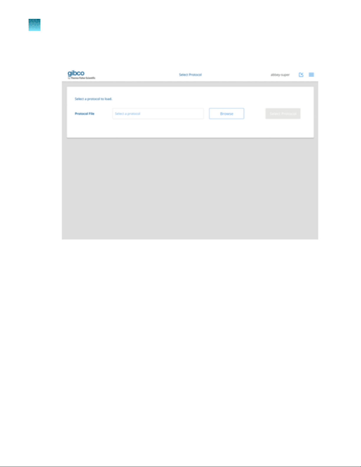
1.
Click on the Select a Protocol button
CTS™ Rotea™ Counterflow Centrifugation System User Guide
27
Page 28
Chapter 2 Installation and setup
2
Download protocols
2.
Click Browse or Select a Protocol to browse for a protocol stored locally or on any connected
devices.
28
CTS™ Rotea™ Counterflow Centrifugation System User Guide
Page 29
Chapter 2 Installation and setup
Download protocols
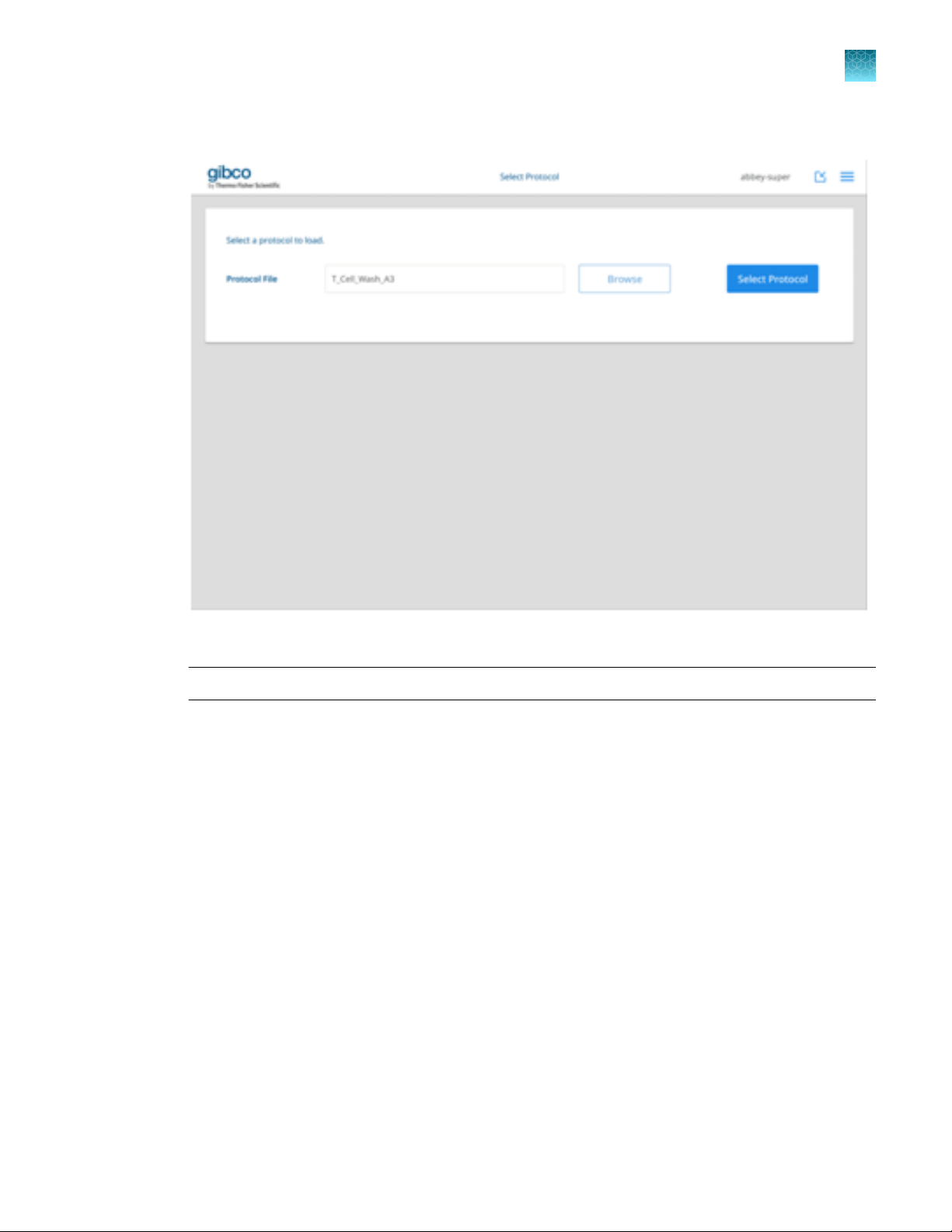
3.
Double click the required protocol to display the filename in the Protocol File text box.
2
4.
Click on Select Protocol.
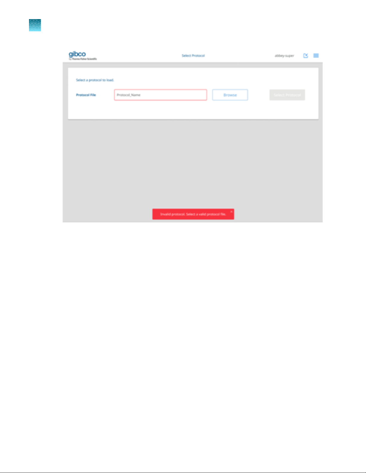
Note: If an invalid protocol is selected, a warning box will be displayed.
CTS™ Rotea™ Counterflow Centrifugation System User Guide
29
Page 30
Chapter 2 Installation and setup
2
Download protocols
30
CTS™ Rotea™ Counterflow Centrifugation System User Guide
Page 31

Rotea™ GUI dashboard
1 2 3 4 5 6
10 9
8
7
The Rotea™ GUI dashboard is the primary means of navigation around the Rotea™ GUI and operation
of the Rotea™ instrument. It can be operated using the laptop touch screen only or with the keyboard
attached.
Chapter 2 Installation and setup
Download protocols
2
Live video of the spinning centrifuge chamber
1
Kit View for the current step
2
Instrument name
3
Protocol name and list of adjacent steps (current step in bold)
4
Username
5
Minimize screen
6
Dropdown menu
7
Shortcut to Step List
8
Manual speed adjustment (buttons or keyed values)
9
Resettable timer
10
CTS™ Rotea™ Counterflow Centrifugation System User Guide
31
Page 32

Chapter 2 Installation and setup
2
Download protocols
User Management
1.
Select User Management from the dropdown menu.
32
CTS™ Rotea™ Counterflow Centrifugation System User Guide
Page 33

2.
Click on the + icon to add a new user.
Chapter 2 Installation and setup
Download protocols
2
3.
Type in new Username and Password.
CTS™ Rotea™ Counterflow Centrifugation System User Guide
33
Page 34

Chapter 2 Installation and setup
2
Download protocols
4.
Confirm new password.
5.
Select Access Level from dropdown list.
6.
Select default folder for saving protocols.
7.
Click Add Account to save new user settings.
8.
Edit user account details including setting Access Level.
34
9.
Click Save or Cancel.
Note: Edits to Access Level can only be performed by a user with admin rights.
CTS™ Rotea™ Counterflow Centrifugation System User Guide
Page 35

10.
Select to delete a user.
Chapter 2 Installation and setup
Download protocols
2
11.
Click Confirm or Cancel.
CTS™ Rotea™ Counterflow Centrifugation System User Guide
35
Page 36

Chapter 2 Installation and setup
2
Download protocols
12.
Users without admin rights can edit their profile by selecting Profile from the dropdown menu.
13.
Edit user profile fields.
14.
Click Save or Cancel.
36
CTS™ Rotea™ Counterflow Centrifugation System User Guide
Page 37

Uninstall
1.
Open the Add or remove programs utility by searching for it in the start menu.
Chapter 2 Installation and setup
Uninstall
2
CTS™ Rotea™ Counterflow Centrifugation System User Guide
37
Page 38

Chapter 2 Installation and setup
2
Logging
2.
Search and remove the Rotea™ application.
3.
Wait for the uninstall to complete and the Rotea™ application will be removed. The user
database and log files will not be deleted when the application is uninstalled. If the user
wants to permanently delete them, they need to be deleted manually by removing the
C:\ProgramData\Rotea directory.
Logging
The application saves several logs. The main logs of interest to the user are the run logs which contain a
run history of each run performed by the laptop.
The run log files are saved in: C:\ProgramData\Rotea\logs\run_logs.
The service logs are saved in: C:\ProgramData\Rotea\logs\service and may be required for
warranty claims and to help resolve application issues.
Note: The ProgramData directory is a hidden directory, typing C:\ProgramData\Rotea in the
address bar will take you to the directory.
38
CTS™ Rotea™ Counterflow Centrifugation System User Guide
Page 39

Chapter 2 Installation and setup
You can also add notes to the run log.
• Click Add Log Comment in the dropdown menu during a protocol run.
Logging
2
CTS™ Rotea™ Counterflow Centrifugation System User Guide
39
Page 40

Chapter 2 Installation and setup
2
Logging
• Write comment in the comment box and click Add Comment.
40
CTS™ Rotea™ Counterflow Centrifugation System User Guide
Page 41

3
Open the door
The instrument door is automatically locked by the instrument and can only be opened when the:
•
Instrument is powered up
•
Blue door unlock button is illuminated
•
Instrument is not currently running a protocol
•
Centrifuge carrier and peristaltic pump are stationary
Basic instrument operation
1.
Press
pushbutton when it is illuminated to unlock the door.
2.
Open the door and raise until past vertical.
Note: Soft close hinges prevent the door from opening or closing abruptly.
CTS™ Rotea™ Counterflow Centrifugation System User Guide
41
Page 42

Chapter 3 Basic instrument operation
3
Open the door
Note: An emergency maintenance access method can be used to open the door should this be
required e.g. in the case of power loss – (See “Open the door without power” on page 111).
When the unlock button is pressed, the safety circuit is disabled to prevent the pump or centrifuge from
operating and triggers the following:
•
Pinch valves retract
•
Pump clamp is released
•
Door is unlocked and partially opens
Note: If there is a Single-Use Kit installed on the instrument, unlocking the door will release the valves
that are clamping the tubes of the kit closed. Any fluids in bags or vessels attached to the kit will be free
to flow. Close all manual tube clamps before opening the door.
42
CTS™ Rotea™ Counterflow Centrifugation System User Guide
Page 43

Kit preparation, loading and removal
Kit configuration
Once a protocol has been selected to run on the instrument, the Kit View on the Rotea™ GUI
dashboard will display a schematic of the CTS™ Rotea™ Single-Use Kit with bag connections.
Chapter 3 Basic instrument operation
Kit preparation, loading and removal
3
Figure 6 Instrument with CTS™ Rotea™ Single-Use Kit
CTS™ Rotea™ Counterflow Centrifugation System User Guide
43
Page 44

Chapter 3 Basic instrument operation
3
Kit preparation, loading and removal
Figure 7 Rotea™ GUI showing Kit View
CAUTION! The Single-Use Kit has been designed exclusively for use with the Rotea
and includes several features to enable fast, error-free loading by the user. It is the responsibility of
the user to ensure correct assembly and loading of the Single-Use Kit prior to initiating an instrument
protocol.
™
instrument
CAUTION! Only use kits supplied by Thermo Fisher Scientific or its agents.
CAUTION! Inspect each Single-Use Kit for any damage or imperfections that may result in incorrect
operation. Do not use kit if any such defect is found.
44
CTS™ Rotea™ Counterflow Centrifugation System User Guide
Page 45

Pre-assembly of processing kit
1.
Peel open the sealed pouch and remove the Single-Use Kit.
Chapter 3 Basic instrument operation
Kit preparation, loading and removal
3
2.
Release the CFC Chamber from the Carrier Frame if still retained.
CTS™ Rotea™ Counterflow Centrifugation System User Guide
45
Page 46

Chapter 3 Basic instrument operation
3
Kit preparation, loading and removal
Connecting vessels, bags and reagents
The instrument has been specifically designed for single use, functionally closed processing. The CTS
Rotea™ Single-Use Kit uses DEHP-Free PVC 0.160” OD tubing to enable sterile welding to compatible
bags using devices that service the blood banking industry such as the TSCD II Sterile Tubing Welder
(TerumoBCT). See the instructions provided by instrument providers for completion of sterile welding.
™
46
Figure 8 TSCD II Sterile Tubing Welder (TerumoBCT)
CTS™ Rotea™ Counterflow Centrifugation System User Guide
Page 47

Bubble Trap
1 2
To manage air in the system, the CTS™ Rotea™ Single-Use Kit includes a small bubble trap with a
capacity of approximately 5 mL.
Chapter 3 Basic instrument operation
Kit preparation, loading and removal
3
Figure 9 CTS™ Rotea™ Single-Use Kit and close-up of Bubble Trap
CTS™ Rotea™ Single-Use Kit
1
Close-up of Bubble Trap
2
CAUTION! Once the Bubble Trap volume is consumed, any additional air in the system will now
be able to enter the CFC Chamber and ultimately cause an over-pressure fault, shutting down the
instrument.
CAUTION! Protocols created for the Rotea
™
instrument must include a suitable priming sequence
to ensure air in fluid supply lines and the Bubble Trap is replaced with fluid prior to commencing
processing.
Note: If the length of tubing from the product supply bag has a volume greater than the Bubble Trap,
then air can enter the circuit. It is therefore preferred that the length of tubing for each connection (1/8”
ID assumed) is less than 12” (or 300 mm). In some cases where the supply vessel is large, e.g. remote
bioreactor, additional process strategies can be included to re-fill the supply tube when needed.
CTS™ Rotea™ Counterflow Centrifugation System User Guide
47
Page 48

Chapter 3 Basic instrument operation
3
Kit preparation, loading and removal
Kit installation
1.
Ensure door is open and any previous Single-Use Kit has been removed.
2.
Hang input / output bags on hanger hooks.
Note: The product input bag can be suspended using one of the side cut-outs on the bag to help
ensure that all product drains from the bag.
48
CTS™ Rotea™ Counterflow Centrifugation System User Guide
Page 49

Chapter 3 Basic instrument operation
Kit preparation, loading and removal
3.
Place the Carrier Frame over the two Single-Use Kit location buttons on the instrument.
3
4.
Install the CFC Chamber into the CFC Chamber Carrier.
a.
Load CFC Chamber into the CFC Chamber Carrier.
b.
Push CFC Chamber down into CFC Chamber Carrier to depress latch.
CTS™ Rotea™ Counterflow Centrifugation System User Guide
49
Page 50

Chapter 3 Basic instrument operation
3
Kit preparation, loading and removal
c.
Slide CFC Chamber away from axis of rotation until the latch clicks.
5.
Insert tubes A, B, C, D, E, F & G into the corresponding slot in the Bubble Detector Strip and push
downwards with fingers to fully engage each tube in the slot.
50
CTS™ Rotea™ Counterflow Centrifugation System User Guide
Page 51

Chapter 3 Basic instrument operation
Kit preparation, loading and removal
6.
Stretch the pump tubing around the Peristaltic Pump rollers and insert the Tube Retainer into the
Sensor Block to hold it in place.
3
Pump tube barbed connector correctly placed in the Sensor Block.
CTS™ Rotea™ Counterflow Centrifugation System User Guide
51
Page 52

Chapter 3 Basic instrument operation
3
Kit preparation, loading and removal
7.
Insert tubing in Sensor Block channel.
52
CTS™ Rotea™ Counterflow Centrifugation System User Guide
Page 53

1
2
Chapter 3 Basic instrument operation
Kit preparation, loading and removal
Correct: Pressure Sensor tubing in
1
Incorrect: Pressure Sensor tubing out
2
CAUTION! The instrument cannot detect if the pump tubing or Tube Retainer have been correctly
positioned. Check prior to closing the door.
3
CAUTION! The tube will sit slightly proud of the channel in the region of the Pressure Sensor so that
the tube is compressed into the required shape when the door is closed. If not correctly located in the
channel, the tubing may be crushed when the door is closed.
CTS™ Rotea™ Counterflow Centrifugation System User Guide
53
Page 54

Chapter 3 Basic instrument operation
3
Kit preparation, loading and removal
Initiate a protocol
1.
Click Initiate to commence running the protocol.
54
CTS™ Rotea™ Counterflow Centrifugation System User Guide
Page 55

2.
Close the door.
Chapter 3 Basic instrument operation
Kit preparation, loading and removal
3
Note: Soft close hinges prevent the door from dropping suddenly.
CTS™ Rotea™ Counterflow Centrifugation System User Guide
55
Page 56

Chapter 3 Basic instrument operation
3
Kit preparation, loading and removal
3.
Push the door downwards to compress the Single-Use Kit tubing onto Pressor Sensors and other
control features.
4.
(auto): Closing the door initiates the following automatic system checks. The status of each system
check is displayed on the Rotea™ GUI with indicating correct installation of the Single-Use Kit.
56
CTS™ Rotea™ Counterflow Centrifugation System User Guide
Page 57

Chapter 3 Basic instrument operation
Kit preparation, loading and removal
5.
Errors detected during the automatic system check are identified with a and will require the user
to identify and rectify the source of the error.
3
CTS™ Rotea™ Counterflow Centrifugation System User Guide
57
Page 58

Chapter 3 Basic instrument operation
3
Kit preparation, loading and removal
6.
Manually confirm that the Single-Use Kit configuration matches the image and that manual clamps
have been opened.
7.
Click Confirm to continue.
CAUTION! Manual clamps are provided for use on input and output lines on the Single-
Use Kit to prevent fluid movement until the instrument Pinch Valves are engaged. However,
manual clamps also represent a significant process hazard if left in the closed state. Whilst
the instrument should detect this failure mode as an over-pressure fault, it will stop the
process potentially compromising the batch. Release all manual clamps prior to starting the
automatic sequence.
If required by the selected protocol:
8.
Enter data inputs.
58
CTS™ Rotea™ Counterflow Centrifugation System User Guide
Page 59

9.
Click Confirm or Cancel.
Chapter 3 Basic instrument operation
Kit preparation, loading and removal
3
CTS™ Rotea™ Counterflow Centrifugation System User Guide
59
Page 60

Chapter 3 Basic instrument operation
3
Kit preparation, loading and removal
10.
The protocol is automatically sent to the instrument and the Rotea™ GUI dashboard is displayed for
the new protocol.
60
CTS™ Rotea™ Counterflow Centrifugation System User Guide
Page 61

Run a protocol
Rotea™ GUI navigation and instrument operation
1.
Press the Start button on the instrument to start the protocol.
2.
Change the Rotea™ GUI dashboard view as required by clicking on the tabs.
Chapter 3 Basic instrument operation
Run a protocol
3
CTS™ Rotea™ Counterflow Centrifugation System User Guide
61
Page 62

Chapter 3 Basic instrument operation
3
Run a protocol
3.
The live video will automatically turn on when the centrifuge speed exceeds 500 × g. The live video
can be manually turned on at any operating speed by clicking on the Turn on video toggle.
62
CTS™ Rotea™ Counterflow Centrifugation System User Guide
Page 63

Chapter 3 Basic instrument operation
Run a protocol
4.
The instrument will automatically progress through each step in the protocol until the protocol is
complete, pre-defined user intervention is required or an error occurs.
3
CTS™ Rotea™ Counterflow Centrifugation System User Guide
63
Page 64

Chapter 3 Basic instrument operation
3
Run a protocol
5.
Depending on user access rights, the user can make in-process adjustments to the following
parameters using the control buttons:
•
Reset Step Time Remaining
•
Increase/reduce Pump flow rate
•
Increase/reduce Centrifuge g-force
6.
Switch to the Step List to see a summary of all steps in the protocol.
64
CTS™ Rotea™ Counterflow Centrifugation System User Guide
Page 65

Chapter 3 Basic instrument operation
7.
Return to the dashboard by clicking on or using the dropdown menu.
Run a protocol
3
CTS™ Rotea™ Counterflow Centrifugation System User Guide
65
Page 66

Chapter 3 Basic instrument operation
3
Run a protocol
Value volumes and pressure sensor values
When in Kit View, click on the Details to display the current net volume that has passed through each
valve and the current pressure of P1 and P2.
66
When the valve volume is positive, more liquid has been pumped out through a valve than has been
pumped in, increasing the volume in the attached bag. A negative value means more liquid has been
pumped in through a valve than has been pumped out, reducing the bag volume.
The example, shows that the net valve volumes are as follows:
1. + 105.2 mL has been pumped out through valve A
2. - 76.0 mL has been pumped in through valve B
3. - 54.6 mL has been pumped in through valve D
4. + 24.9 mL has been pumped out through valve G
5. A small volume of + 0.3 mL has been pumped out through valves E & F which occurred during the
Prime Pressure step.
CTS™ Rotea™ Counterflow Centrifugation System User Guide
Page 67

Note:
The valve volumes are not the same as the volume that has entered or left a bag. In the example
·
shown, the input bag (cells in culture) is a dual port bag connected to both valve D and G. To
calculate the volume change in or out of the input bag, add the valve volumes for valves D and G e.g.
- 54.6 + 24.9 = - 29.7mL (out of the input bag)
The valve volume is the volume displaced by the pump and hence does not account for volume
·
retained in the Single-Use Kit during priming. For example, the net volume for valve A would overestimate the volume that has been delivered to the waste bag by the volume of the CFC Chamber
plus the kit tubing.
Note: The Pressor Sensors, P1 and P2, are at a low negative pressure meaning there is a slight
vacuum in the system. These will fluctuate during processing depending on the flow rate and pump
direction. A rapidly increasing Pressure Sensor value would indicate a flow restriction or blockage.
Error messages
Chapter 3 Basic instrument operation
Run a protocol
3
Alarm or
message
Safety system
error
Protocol is
Malformed
Door lock error Yes — Trigger instrument stop state Door lock error
Critical
alarm
Yes — Cut power to pump and
Yes — GUI error message after loading
Warning Instrument response GUI message
centrifuge, trigger instrument
stop state
protocol will appear
Safety system error
Protocol run has stopped.
Press the stop button on
the instrument, close manual
clamps and open and close
the instrument door to reset.
Restart the protocol or select
a protocol step to start from. If
error persists, abort the run.
Protocol is Malformed error
Note: Check pump calibration
number to ensure protocol flow
rates are within range.
Protocol run has stopped.
Open and close the door, then
restart the protocol. If error
persists, abort the run.
Pump error Yes — Trigger instrument stop state Pump error
Protocol run has stopped.
Press the stop button to clear
the error, then restart the
protocol or select a step to
start from. If error persists,
abort the run.
CTS™ Rotea™ Counterflow Centrifugation System User Guide
67
Page 68

Chapter 3 Basic instrument operation
3
Run a protocol
(continued)
Alarm or
message
Centrifuge error Yes — Trigger instrument stop state Centrifuge error
Valve error Yes — Trigger instrument stop state Valve error
Out of balance
condition
Critical
alarm
Yes — Trigger instrument stop state Instrument out of balance
Warning Instrument response GUI message
Protocol run has stopped.
Press the stop button on
the insturment, close manual
clamps and open and close
the instrument door to reset.
Restart the protocol or select
a protocol step to start from. If
error persists, abort the run.
Protocol run has stopped.
Press the stop button on
the instrument, close manual
clamps and open and close
the instrument door to reset.
Restart the protocol or select
a protocol step to start from. If
error persists, abort the run.
Protocol run has stopped.
Press the stop button to clear
the error, then restart the
protocol or select a step to
start from. If error persists,
abort the run.
Moisture in bowl Yes — Trigger instrument stop state Centrifuge leak detected
Protocol run has stopped.
Press the stop button to
clear the error or temporarily
override the moisture sensor if
safe to do so. If error persists,
abort the run.
68
CTS™ Rotea™ Counterflow Centrifugation System User Guide
Page 69

(continued)
Chapter 3 Basic instrument operation
Kit removal
3
Alarm or
message
Over-pressure
condition
Communication
error
Kit removal
CAUTION! Seal all fluid lines using a tube sealer or manual clamps prior to unlocking the door to
prevent fluid movement when the instrument pinch valves are released.
Critical
alarm
Yes — Trigger instrument stop state Blockage detected
— Yes Instrument continues running
Warning Instrument response GUI message
Protocol run has stopped.
Ensure manual clamps are
open and bags are connected
correctly. Press the stop button
to relieve pressure to Bag X.
Restart the protocol or select a
protocol step to start from.
Communication error
protocol, GUI indicates error
until communications are
restored
Ensure that the cable between
the laptop interface and
instrument is connected.
1.
Press pushbutton when it is illuminated to unlock the door.
CTS™ Rotea™ Counterflow Centrifugation System User Guide
69
Page 70

Chapter 3 Basic instrument operation
3
Kit removal
2.
Open the door and raise until past vertical.
70
CTS™ Rotea™ Counterflow Centrifugation System User Guide
Page 71

Chapter 3 Basic instrument operation
Kit removal
3.
Remove the CFC Chamber from the CFC Chamber Carrier by lifting the lever and rotating the CFC
Chamber back towards the latch.
3
CTS™ Rotea™ Counterflow Centrifugation System User Guide
71
Page 72

Chapter 3 Basic instrument operation
3
Kit removal
4.
Lift CFC Chamber clear of the Centrifuge Carrier.
72
CTS™ Rotea™ Counterflow Centrifugation System User Guide
Page 73

5.
Remove the tubing from the Sensor Block and Peristaltic Pump.
Chapter 3 Basic instrument operation
Kit removal
3
CTS™ Rotea™ Counterflow Centrifugation System User Guide
73
Page 74

Chapter 3 Basic instrument operation
3
Aseptic disconnection of the kit components
6.
Gently raise the Carrier Frame drawing out the tubes from the Bubble Sensor.
Aseptic disconnection of the kit components
If not done prior to Single-Use Kit removal from the instrument:
•
Create sterile seal and disconnect finished product from the Single-Use Kit.
•
Create sterile seal and disconnect any bags or subassemblies to be disposed of separately or
manually clamp tube connections to bags if preferred.
•
Dispose of used Single-Use Kit in accordance with approved procedures.
Note: The Single-Use Kit tube materials are suitable for RF sealing using a SEBRA or Terumo Tube
Sealer or equivalent. Please consult the tube sealer supplier’s manual for instructions on creating a
sterile disconnection.
74
CTS™ Rotea™ Counterflow Centrifugation System User Guide
Page 75

System settings
Instrument firmware
1.
Select Settings from the drop down menu.
Chapter 3 Basic instrument operation
System settings
3
CTS™ Rotea™ Counterflow Centrifugation System User Guide
75
Page 76

Chapter 3 Basic instrument operation
3
System settings
2.
Click on the Firmware tab.
3.
Select the latest firmware.
4.
Click Update.
76
CTS™ Rotea™ Counterflow Centrifugation System User Guide
Page 77

5.
The selected firmware will be automatically updated.
Chapter 3 Basic instrument operation
System settings
3
CTS™ Rotea™ Counterflow Centrifugation System User Guide
77
Page 78

Chapter 3 Basic instrument operation
3
System settings
6.
The system will automatically reboot.
7.
Once firmware has updated successfully, click Done.
78
CTS™ Rotea™ Counterflow Centrifugation System User Guide
Page 79

Chapter 3 Basic instrument operation
8.
If firmware has not been updated click Done and restart the firmware update.
System settings
3
CTS™ Rotea™ Counterflow Centrifugation System User Guide
79
Page 80

Chapter 3 Basic instrument operation
3
System settings
OPC-UA
An Open Platform Communications - United Architecture (OPC-UA) interface is provided that enables
admin users to connect Rotea™ instrument to a Supervisory Control and Data Acquisition (SCADA)
system to send protocols, start a protocol and monitor run progress, see Chapter 4, “OPC-UA
interface”.
80
CTS™ Rotea™ Counterflow Centrifugation System User Guide
Page 81

Settings
Admin users have the ability to update the instrument settings via the Rotea Settings tab.
Chapter 3 Basic instrument operation
System settings
3
CTS™ Rotea™ Counterflow Centrifugation System User Guide
81
Page 82

Chapter 3 Basic instrument operation
3
System settings
Licenses
All relevant software licenses are listed in the Licenses tab. The detail for each license can be displayed
by clicking on the v arrows.
82
CTS™ Rotea™ Counterflow Centrifugation System User Guide
Page 83

Calibration
1.
Select Calibration ( ) from the drop down menu.
Chapter 3 Basic instrument operation
Calibration
3
CTS™ Rotea™ Counterflow Centrifugation System User Guide
83
Page 84

Chapter 3 Basic instrument operation
3
Calibration
2.
Input Target Volume.
3.
Input Actual Volume from calibration test run.
4.
Select Kit Type from the drop down list.
5.
Click Calibrate.
84
CTS™ Rotea™ Counterflow Centrifugation System User Guide
Page 85

6.
Click Save or Cancel.
Chapter 3 Basic instrument operation
Calibration
3
CTS™ Rotea™ Counterflow Centrifugation System User Guide
85
Page 86

Chapter 3 Basic instrument operation
3
Calibration
7.
Click Done if calibration is successful.
8.
If calibration was not successful, click Done and restart the calibration process.
86
CTS™ Rotea™ Counterflow Centrifugation System User Guide
Page 87

4
Introduction
There are applications for the CTS™ Rotea™ Counterflow Centrifugation System where a Supervisory
Control and Data Acquisition (SCADA) system will supervise the operation. This supervision will include
items like sending a protocol to the Rotea™ instrument, starting a protocol and monitoring of run
progress.
Each CTS™ Rotea™ Counterflow Centrifugation System includes a dedicated Dell™ 2‑in‑1 laptop with
software applications to program and operate the instrument. An open data communication interface is
also included to interface with SCADA systems.
One SCADA system is the Emerson DeltaV. DeltaV is technically a Process Control System (PCS), but it
incorporates all the functionality of a SCADA system, and those are the functions that will be primarily
used with the Rotea™ instrument.
OPC-UA interface
Definitions
Abbreviation
GUI Graphical User Interface
DeltaV A Process Control System (PCS made by Emerson
ERP Enterprise Resource Planning
MES Manufacturing Execution System
PCS Process Control System
PLC Programmable Logic Controller
Protocol A series of equipment instructions
Run The execution (running) of a protocol, from beginning to end
SCADA Supervisory Control and Data Acquisition
OPC-UA Open Platform Communications - United Architecture, a machine to
Definition
machine communication protocol for industrial automation
CTS™ Rotea™ Counterflow Centrifugation System User Guide
87
Page 88

4
Chapter 4
Scope of system
OPC-UA interface
Scope of system
CTS™ Rotea™ Counterflow Centrifugation System is a stand alone instrument with an operational
configuration comprising:
• The instrument hardware
• Firmware and software
• Dell™ 2‑in‑1 laptop
• The installed CTS™ Rotea™ Single-Use Kit and attached tubing and bags/vessels
• The protocol file
• In-process data that is supplied as protocol metadata before the protocol commences
Instrument hardware configuration
The Rotea™ instrument's embedded control has been designed to enable integration of functional
components that are external to the base instrument and hence would vary the configuration from the
standard:
• External components may be externally powered
• Communications from the Rotea™ instrument's embedded control to external components is
through a CAN-BUS interface
• External devices may be individual devices already defined in the Rotea™ instrument's embedded
schema such as a pump, centrifuge, push button, bubble sensor or valve
• External devices may be newly defined with a set of device specific commands and status reports
• External devices may also comprise a series of components managed by a self-contained control
that responds to purpose designed messages from the Rotea™ instrument's embedded through the
CAN-BUS
Single-Use Kit
The Single-Use Kit defines:
• The fluidic connections between instrument components such as the pump and valves
• The size of the pump tubing for each pump
• Optionally the volume capacity of each attached bag/vessel
• Optionally the priming volume for each valve line
• Optionally the required minimum volume for each reagent supply to be attached
The Single-Use Kit is identified by:
• A barcode read from a label attached to the kit
• The kit identification includes a unique number, batch identification number and kit type specifier.
The kit type specifier is used for verification of kit type to the protocol requirements.
The scope of a Single-Use Kit may extend beyond the base instrument to include attached devices
such as external mixers and pumps, or simply the tubing or other features that facilitate connection to
external systems such as bio-reactors or electroporation systems that are not managed by the Rotea
instrument's control.
88
™
CTS™ Rotea™ Counterflow Centrifugation System User Guide
Page 89

Protocol file
• Protocol files for the Rotea™ instrument will be stored and transmitted in JSON format.
• The JSON format provides an extensible structure to support future devices and software
functions.
• The Rotea™ instrument's embedded control supports one only protocol file.
• The protocol file is re-written to the instrument each time the protocol is run.
Protocol metadata
Protocol metadata entries provide the means to adjust fixed, qualified protocols to respond to process
conditions.
• Metadata is supplied at the time the protocol is transferred to the instrument
• The metadata populates variables that are needed to complete the protocol definition
• This is managed by the IAL as part of the protocol transfer actions
Chapter 4
OPC-UA interface
MES interface
4
MES interface
A Manufacturing Execution System (MES) interface is provided to enable processing by the Rotea
instrument within a qualified clinical cGMP environment.
Background
The CTS™ Rotea™ Counterflow Centrifugation System is for research use or manufacture of cell, gene or
tissue-based products.
For use in a qualified manufacturing processes, the instrument, Single-Use Kit and protocol must be
qualified and maintained fit for purpose for the application.
When a qualified process is run, a record is required to verify that the process was performed in the
formally defined way. If any variation to the process operations occur, then such events need to be
documented and formally reviewed before the product can be released.
An MES interface is a communication system that links the CTS™ Rotea™ Counterflow Centrifugation
System to a formally qualified electronic batch management system and associated data capture and
record management functions.
The MES system is responsible for formal identification of users, their level of training, recording of
equipment, consumables and events associated with each processing run.
The CTS™ Rotea™ Graphical User Interface (GUI) does not support this formal data capture activity.
If an automated electronic interface is part of the implementation plan for CTS™ Rotea™ Counterflow
Centrifugation System, then the MES interface provides that tool.
™
CTS™ Rotea™ Counterflow Centrifugation System User Guide
89
Page 90

Chapter 4 OPC-UA interface
4
MES interface
Electronic communications
It is assumed the MES applications will be located externally to the CTS™ Rotea™ Counterflow
Centrifugation System.
Communications by any MES system to the instrument will be through the CTS™ Rotea™ GUI installed
on the Dell™ 2‑in‑1 laptop attached to the instrument. View the structure diagram, see “MES run a
protocol” on page 104.
Figure 10 System components
Communications protocol
The MES interface to the Rotea™ instrument application will be through an implementation of OPC-UA.
When enabled in the Rotea™ GUI, an OPC-UA server will run on the laptop allowing an MES OPC-UA
client to connect to it.
The commands and reports available to OPC-UA client are outlined (see “MES – Commands and
reports overview” on page 91) with details (see “OPC-UA interface” on page 96).
90
CTS™ Rotea™ Counterflow Centrifugation System User Guide
Page 91

MES – Commands and reports overview
Chapter 4
MES – Commands and reports overview
OPC-UA interface
4
Figure 11 Run protocol workflow
For more use cases, See “Use case sequence diagrams” on page 104.
CTS™ Rotea™ Counterflow Centrifugation System User Guide
91
Page 92

Chapter 4
4
MES – Commands and reports overview
OPC-UA interface
Enable OPC-UA
The OPC-UA interface is not enabled by default. The enable button is available to an administrator
under the Settings: OPC-UA Setup tab. The OPC-UA server only supports one OPC-UA client
connecting to it. The Rotea™ application uses a Unified Automation OPC-UA stack which supports
a number of configurable parameters, including: encryption level, security level, certificate configuration,
valid certificates, end point addresses, server names, server url, etc. The full list of parameters can
be found at the following link. http://documentation.unified-automation.com/uasdkcpp/1.7.0/html/
L2ServerSdkServerConfig.html#server_config_xml_file
The Rotea™ application configuration file is available on the laptop under:
C:\Program Files (x86)\Rotea\opcua\opcua_server_config.xml
The user can modify the configuration file to suit their needs. The configuration file is loaded when the
laptop is started if the OPC-UA server is enabled or when the OPC-UA server is enabled under the
OPC-UA Setup tab.
Log in to instrument
The MES can login to the Rotea™ GUI at any time, it does so by changing the SetGuiUserLevel node.
Full details of the SetGuiUserLevel values, see “OPC-UA interface” on page 96.
Load protocol
A protocol can be loaded three ways:
1. SetLocalProtocolFilePath – Sets the file path on the laptop of where to load the protocol file.
2. SetProtocolFileContents – Supply the protocol file contents to transfer to Rotea™ GUIRotea™ and
the instrument.
3. SetProtocolFileByLookupTableId – Select a protocol based on the id in a lookup table. The user
must generate a YAML file called OPCUAProtocolList.yaml with the ids and filenames in it.
This is an example OPCUAProtocolList.yaml file with 2 files in it:
The user must set the directory where the OPCUAProtocolList.yaml file can be found. This is done
on the OPC-UA settings page.
Note: The YAML file can be modified in any text editor. Freeware program NotePad++ is used in the
illustration.
92
Confirmation of protocol loading can be obtained from the ProtocolName and ProtocolChecksum
reports. ProtocolCheckSum can be used to verify integrity of protocol file transfer from uncontrolled
repositories.
CTS™ Rotea™ Counterflow Centrifugation System User Guide
Page 93

The protocol checksum is an hexidecimal number with 32 characters.
Example: e152abb59e4949980731c5bbf7194b
It can be saved and compared as a string.
The ProtocolState report should now report ProtocolSelected.
Load kit
The instrument verification process needs the instrument door to be closed and a valid kit to be
detected. The kit ID is read by the instrument when the door is closed.
The DoorState is reported Closed, and the KitID string is supported by KitState report that checks the
kit type against that required for the protocol. If the kit ID is valid and aligned to the protocol then the
KitState is reported as valid.
Transfer metadata
Protocols can be defined with metadata or parameters that allow a qualified recipe to respond to
changing input materials and output targets.
Chapter 4
MES – Commands and reports overview
OPC-UA interface
4
Refer to the sequence diagram, see “MES drives Rotea in response to external systems” on page 106.
After the protocol information is loaded the instrument will set ParameterName1 through
ParameterName20 to the names of the variables that need to set in the protocol metadata.
The MES can check ParameterValid1 to ParameterValid20 to determine the status of metadata
definition for the protocol. This will advise if that parameter is in use, if it has been set, and if the
setting is valid.
To set the value, use SetParameter1 through SetParameter20 and supply an Int32 value.
Initialize protocol on to instrument
Once the protocol has been specified, kit loaded and any metadata defined within acceptable ranges,
set the SetProtocolState to SendProtocolToRotea.
The protocol definition is sent to the instrument and ProtocolState will report ProtocolReadyToStart.
Start/Stop/Pause/Resume protocol
• The MES can Start, Stop and Pause/Resume the instrument with SetProtocolState variable.
• The ProtocolState will report ProtocolRunning.
• These actions are available through the buttons on the instrument when enabled.
• The MES can disable Start, Pause and Advance functions with the SetSkipButtonEnable and
SetPlayPauseButtonEnable. When the buttons are enabled they will follow the configuration in the
protocol file, if they are disabled the buttons on the instrument are disabled.
CTS™ Rotea™ Counterflow Centrifugation System User Guide
93
Page 94

Chapter 4 OPC-UA interface
4
MES – Commands and reports overview
• When the instrument completes the protocol or is stopped for any other reason, the instrument
state will be reported as InstrumentReady. This provides the option for the protocol to be restarted using StartatStep or other administrator actions from the InstrumentReady state.
• When a user with administrator authority is logged in via the MES or without MES supervision, the
Pause and Advance instrument buttons become active independent of protocol settings.
Instrument run status
The instrument status can be monitored on the Rotea™ GUIor via the exposed OPC-UA variables.
• The ProtocolState will report ProtocolRunning or ProtocolPaused.
• The ProtocolStepNumber reports the current step.
• WaitingUserAck reports if the instrument is waiting for verification to proceed to the next step or
repeat the current step. The MES uses SetProtocolState to RunProtocol to repeat the same step,
or SkipToNextStep in response to this state.
MES batch history data
• The Rotea™ Run Manager captures the run history data into a unique file each time the protocol is
run.
• Run history contains details of the process conditions throughout the run.
94
CTS™ Rotea™ Counterflow Centrifugation System User Guide
Page 95

Alarm recovery tools
• Alarm reset commands; these may include active instrument reactions such as opening valves for a
controlled period to release pressure.
• Several options for product recovery are available through MES commands:
– Re-start the protocol at a specified step. The protocol can contain dedicated blocks of code
independent of the main process.
– Download a new protocol and start it at a specified step
– Start running the settings of a single step in the existing protocol.
• The MES can also log in a qualified user with administrative privileges to run the instrument from
the Rotea™ GUI as a manual intervention.
– All actions are recorded in the history files and instrument status is reported to the MES
– To return to MES managed operations, the administrator user logs out of the MES. The MES
then logs in as ViewUser again. (The instrument can be running the protocol while users/MES
log in and log out.)
Chapter 4 OPC-UA interface
MES – Commands and reports overview
4
Figure 12 OPC-UA enabled administrator to perform recovery
CTS™ Rotea™ Counterflow Centrifugation System User Guide
95
Page 96

Chapter 4 OPC-UA interface
4
OPC-UA interface
OPC-UA interface
Commands OPC-UA to Rotea™ application
Table 2 OPC-UA command list
Variable Type Values/Description
RescanKit Boolean Force a kit rescan:
SetGuiUserLevel Enum • GUIManagedLogin – Application login
• True – The instrument will rescan the kit
barcode.
• False – No action.
is managed by the GUI, OPC-UA
commands are ignored in this mode.
• ViewUser – The MES has control of the
Rotea™ instrument and GUI just displays
the instrument status.
• AdminUser – The GUI is logged in as
an administrator and has control the
Rotea™ instrument, OPC-UA commands
are ignored in this mode.
Note: When OPC-UA enabled, a
SetGuiUserLevel command from the OPC-UA
server will over-ride the current instrument login state.
SetLocalProtocolFilePath String Set the file name path of the protocol on the
laptop to be loaded to the Rotea™ instrument.
SetPlayPauseButtonEnable Enum Enable the Play/Pause button on the Rotea
instrument.
• Disabled
• AsPerProtocol
• Enabled
SetProtocolFileContents String Send the protocol file contents to the laptop to
be loaded to the Rotea™ instrument.
SetProtocolFileByLookupTableId UInt32 Id of the protocol file in the OPC-UA look
up table. The lookup table is defined in
™
OPCUAProtocolList.yaml
SetParameter1 through SetParameter20 Int32 The Metadata parameter data for the protocol.
The associated name of the parameter can be
found in variables ParameterName1 through
ParameterName20 after the protocol has been
loaded.
96
CTS™ Rotea™ Counterflow Centrifugation System User Guide
Page 97

Chapter 4 OPC-UA interface
OPC-UA interface
Table 2 OPC-UA command list (continued)
Variable Type Values/Description
SetProtocolState Enum • StopProtocol – Stop the protocol.
• SendProtocolToRotea – Load the
protocol to the Rotea™ instrument.
• RunProtocol – Start the protocol, same
as pressing the Start button on the
instrument.
• PauseProtocol – Pause the protocol
• RecoveryRunProtocolFromStep – Start
a protocol from the step specified in
SetRecoveryStepNumber.
• RecoveryRunProtocolFromStep – Start
a protocol from the step specified in
SetRecoveryStepNumber.
• RecoveryRunProtocolSingleStep – Start
a protocol and run a single step number
SetRecoveryStepNumber.
• SkipToNextStep - advances the protocol
to the next step by ending this step.
4
SetRecoveryStepNumber UInt32 The recovery step number to start from. Used
SetSkipButtonEnable Enum Enable the advance button on the Rotea
Reports Rotea™ application to OPC-UA
Table 3 Variable set when changed
Variable
CentrifugeSpeed UInt32 The current centrifuge speed
InstrumentName String The name of the instrument, stored on the
MainFirmwareVersion String The main board firmware version on the
ModelNumber String The model number of the instrument, set
by SetProtocolState.
™
instrument:
• Disabled
• AsPerProtocol
• Enabled
Type Value/Description
instrument, set by the GUI
instrument
during manufacture
CTS™ Rotea™ Counterflow Centrifugation System User Guide
97
Page 98

Chapter 4 OPC-UA interface
4
OPC-UA interface
Table 3 Variable set when changed (continued)
Variable Type Value/Description
PowerFirmwareVersion String The power board firmware version on the
RoteaAppVersion String The Rotea™ application version
RoteaLinkUp Boolean The Rotea™ link state:
SerialNumber String The serial number of the instrument, set during
instrument
• True – The Rotea™ application is
connected to the instrument and
communication is successful.
• False – The Rotea™ application cannot
communicate with the instrument, all
commands will fail and the status is
invalid.
manufacture
UpTime UInt32 Number of seconds the server has been
running, updated every 10 seconds
98
CTS™ Rotea™ Counterflow Centrifugation System User Guide
Page 99

Chapter 4 OPC-UA interface
OPC-UA interface
Table 3 Variable set when changed (continued)
Variable Type Value/Description
WaitingUserAck Enum Instrument has entered pause state. This will
also cause the ProtocolState to transition to
ProtocolPaused.
The initiating event for this pause state is
described:
• NotWaiting - Not waiting for User
acknowledge
• WaitingBubbleAck - Waiting for User
acknowledge following pause on a bubble
trigger event
• WaitingPressureAck - Waiting for User
acknowledge following pause on pressure
trigger event
• UserPausedButton – The user paused
the protocol via the pause button on the
instrument
• UserPausedOPCUA – The user paused
the protocol via the OPCUA interface
•
4
In order to acknowledge the event;
The user can press a play/advance buttons (if
enabled) on the instrument.
The MES can write the:
• ProtocolState to RunProtocol to continue
with the current step
or
• ProtocolState to SkipToNextStep to
advance
CTS™ Rotea™ Counterflow Centrifugation System User Guide
99
Page 100

Chapter 4 OPC-UA interface
4
OPC-UA interface
Table 3 Variable set when changed (continued)
Variable Type Value/Description
ProtocolEnded Enum The state indicates that the protocol has
stopped and the reason that it stopped. Press
the stop button or write the ProtocolState to
StopProtocol will clear any Errors.
• NotApplicable – Not Applicable
• CompletedSuccessfully – Protocol
completed successfully
• UserStoppedRun – The user or OPC-UA
stopped the protocol
• DoorUnlatchedError – The instrument has
raised a door error; the door failed to
close or has opened unexpectedly
• PumpMotorError – The instrument has
raised a pump motor fault
• CentrifugeMotorError -The instrument
has raised a centrifuge motor fault
• ValveError – The instrument has raised
a valve error. A valve may have failed to
close or open properly
• OutOfBalanceError – The instrument has
raised an out of balance error, the
centrifuge may be out of balance
• MoistureInBowlError – The instrument
has raised a moisture in bowl error, the kit
may be leaking
• OverPressureConditionError – The
instrument has raised an over pressure
error; excessive pressure has been
detected in one of the kit tubes
• UnknownError – The instrument is in an
unknown error state
100
DoorState
Enum • DoorOpened – The door is closed
• DoorClosed – The door is open
CTS™ Rotea™ Counterflow Centrifugation System User Guide
 Loading...