

Page 1

Instruction Manual - Web Remote Edition -
ATUC-50
Digital Wired Conference System
Gooseneck Microphone with LED Ring
ATUC-M43H/58H/M32L
Discussion Unit
ATUC-50DU/ATUC-50DUa
Interpretation Unit
ATUC-50INT
Control Unit
ATUC-50CU
Integration Unit
ATUC-50IU
Link Extender
ATLK-EXT165
Voting Unit
ATUC-VU
ATUC-IR
Hybrid Infrared Conference System
Gooseneck Microphone with LED Ring
ATUC-M43H/58H/M32L
IR Discussion Unit
ATUC-IRDU
Hybrid Control Unit
ATUC-IRCU
Hybrid Control Unit (Dante-Enabled)
ATUC-IRCUDAN
IR Transmitter Unit
ATUC-IRA
IR Distributor
ATUC-IRD
Charger
ATCS-B60
Page 2

Table of Contents
Introduction .......................................... 3
About this manual .................................................. 3
About the information in this manual ..................................... 3
About the configuration of this manual ................................... 3
About registered trademarks and copyrights .......................... 3
Preparing to use Web Remote ...............................4
What is Web Remote? ............................................................... 4
Setting up “Locate” ................................................................... 4
Configuring and Operating Conferences
Using the Web Remote Control
Function ................................................. 5
About Web Remote ................................................5
Overall structure of Web Remote ............................................ 5
Starting up Web Remote and preparing for
operations ..............................................................6
Starting up and logging in to Web Remote .............................. 6
About Web Remote Home screen ............................................ 6
Configuring detailed system settings
([Settings & Maintenance]) .................................... 7
How to operate the [Settings & Maintenance] menu .............7
Menu item ① ([System Settings]) .......................................... 8
Menu item ② ([Install Settings]) .......................................... 16
Accessing your presets ([Presets]) ........................................ 30
Log management ([Logging]) ............................................... 30
Displaying the system information ([System Info]) ............. 30
Preparing for conferences
([Setup Conference]) ............................................31
Recalling the preset ([Recall Preset]) ............................. 31
1
Changing the conference settings
2
([Conference Settings]) ...................................................31
Adjusting the DU/IU settings
3
([DU/IU Settings], [DU/IU Detail Settings]) ............... 32
Operating and controlling conferences
([Start Conference]) .............................................33
Operating conferences ([Conference Manager]) ............ 33
1
Configuring the advanced audio-related settings and
2
performing audio operations ([Audio Control]) ............ 34
Configuring conference settings
3
([Conference Settings]) ...................................................34
Information.......................................... 35
Troubleshooting ...................................................35
Error messages .....................................................36
2
Page 3

Introduction
About this manual
About the information in this manual
The images and screenshots shown in this manual may differ from
the actual product.
About the configuration of this manual
The “Web Remote Edition” instruction manual explains how to use
Web Remote. Refer to the “Main Unit Edition” for information
about the digital wired conference system ATUC-50 and the hybrid
infrared system ATUC-IR products.
Device names
The device names are abbreviated as follows.
• 50CU: “Control Unit” ATUC-50CU
• 50DU: “Discussion Unit” ATUC-50DU/ATUC-50DUa*
• 50INT: “Interpretation Unit” ATUC-50INT
• ATUC-M: “Gooseneck Microphone with LED Ring” ATUCM43H/ATUC-M58H/ATUC-M32L
• 50IU: “Integration Unit” ATUC-50IU
• EXT: “Link Extender” ATLK-EXT165
• VU: “Voting Unit” ATUC-VU
• IRCU: “Hybrid Control Unit” ATUC-IRCU
• IRCUDAN: “Hybrid Control Unit (Dante-Enabled)” ATUC-
IRCUDAN
• IRDU: “IR Discussion Unit” ATUC-IRDU
• IRA: “IR Transmitter Unit” ATUC-IRA
• IRD: “IR Distributor” ATUC-IRD
• B60: “Charger” ATCS-B60
Operations on mobile devices
Operations in this manual assume that you are using a computer as a
control device. Alternatively you can use a mobile device such as a
tablet. Instead of clicking or double-clicking, operate the application
by tapping.
About registered trademarks and copyrights
• Apple, the Apple logo, iPad and Mac OS are trademarks of Apple
Inc., registered in the U.S. and other countries. App Store is a
service mark of Apple Inc.
• Google Play and the Google Play logo are registered trademarks
or trademarks of Google Inc.
• Other product names, service names, logos and/or company
names used in this manual are trademarked and copyrighted
properties of their respective owners and/or licensors.
In this manual, the TM and
mark may not be specified.
®
* The ATUC-50DUa is a conference microphone unit that is
compatible with the ATUC-VU (Voting Unit).
Some abbreviated names are used as follows.
CU: When indicating the ATUC-50CU, ATUC-IRCU, and ATUC-
IRCUDAN collectively
DU: When indicating both the ATUC-50DU/ATUC-50DUa and
the ATUC-IRDU
Symbols
➤
NOTICE
[ ]
Indicates the page(s) where you can find more detailed
or related information.
Indicates a risk that may result in malfunction or damage
to the device.
Indicates supplementary information as well as tips &
advice for operations.
Indicates menu items on the Web Remote screen.
3
Page 4

Preparing to use Web Remote
What is Web Remote?
For iOS users:
Search from App Store and install “Locate”.
Web Remote is a web application to control this system.
Using Web Remote enables you to remotely perform the following
operations from a computer or mobile device (hereinafter, control
device):
• Preparing for conferences
• Operating and controlling conferences
• Configuring detailed settings
After connecting the CU to the control device, download “Locate”.
Using “Locate” enables you to simply access Web Remote
page6) without typing the IP address of the installed CU.
(
➤
• You can also start up Web Remote without using
“Locate” (
Operating Environment for Web Remote and “Locate”
• Microsoft Windows 7 or later
• Apple OS X10.12 Sierra or later
• Android OS5.0 or later
• iOS9 or later
Recommended web browser for Web Remote
• Microsoft Internet Explorer 11 (Windows)
• Google Chrome ver. 57 or later (Windows and Android)
• Mozilla Firefox ver. 52 or later (Windows)
• Safari 10 or later (OS X and iOS)
NOTICE
• Up to 3 control devices can simultaneously log in to Web
Remote.
When 2 web browsers are running on a control device,
Web Remote counts the web browsers as 2 separate
devices.
• When you have finished with Web Remote, be sure to log
out of Web Remote before closing the web browser
window.
If you simply close the window without logging out, you
will remain logged in to Web Remote for 5 minutes until
the session times out.
page6).
➤
Proceed to step 4.
For Android users:
Search from Google Play and install “Locate”.
Proceed to step 4.
Double-click “setup.exe” downloaded.
2
The setup wizard will appear.
Follow the on-screen instructions to install
3
“Locate” onto the control device.
After the installation is complete, the “Locate” icon will appear
on the desktop.
Check that the CU and the control device are
4
connected to the same network, and that the
power of the CU is ON, then double-click the
“Locate” icon.
“Locate” starts up. CUs connected to the network are detected
automatically.
Select the CU you want to control via Web
5
Remote, then click [Open].
Setting up “Locate”
Download the “Locate” installer onto the control
1
device.
For Windows/Mac users:
Download the “Locate” installer that applies to your country/
region from the Audio-Technica website:
http://www.audio-technica.com/world_map/
Proceed to step 2.
The Web Remote login screen appears.
• When the [Identify] icon is clicked, the icon lights red
and the indicators blink on the front panel of the selected
CU. This function is useful if there are multiple CUs in
the system and you want to identify a CU, such as when
you select the CU you want to control from the CUs
displayed in the “Locate” list.
4
Page 5
Configuring and Operating Conferences Using the Web Remote Control Function
About Web Remote
Overall structure of Web Remote
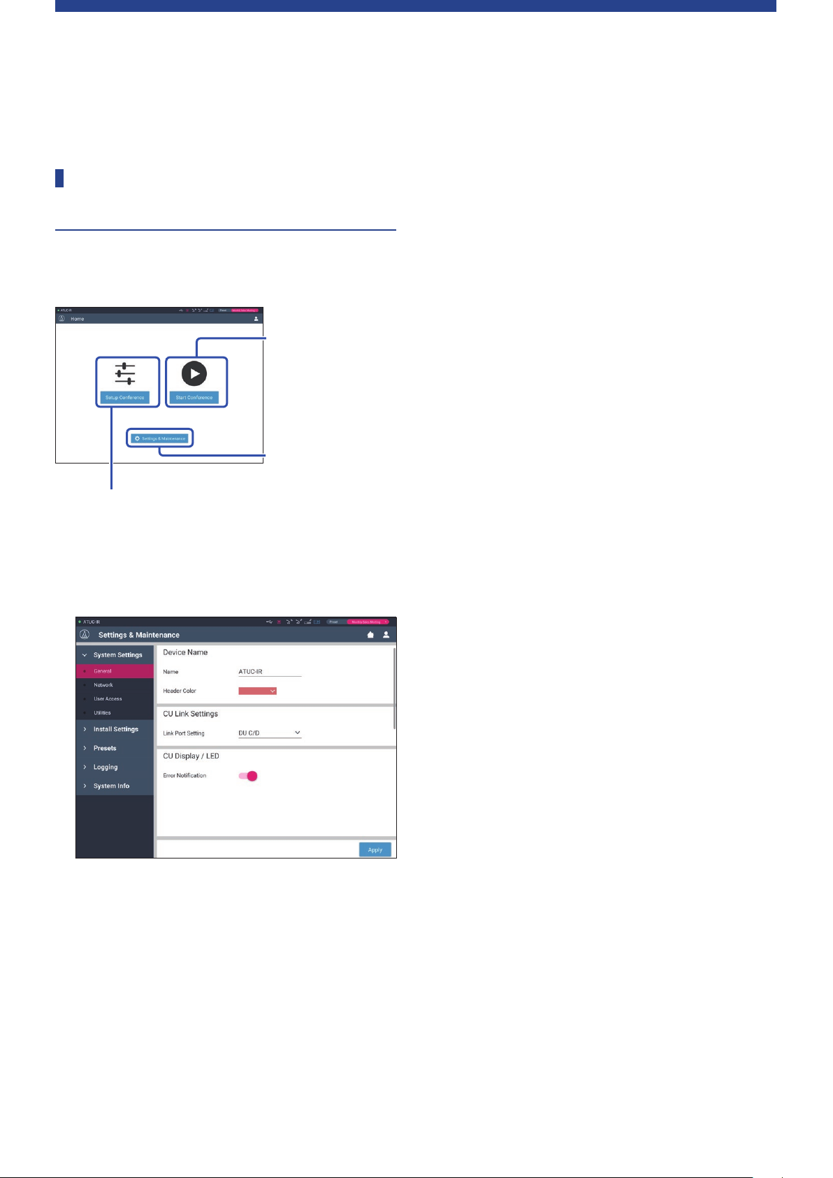
From the Home screen below, you can access the 3 main menus.
3. Operating and
controlling conferences
(Start Conference)
→
Select this to start a
conference using the
current settings.
1. Configuring detailed
settings of the system
(Settings & Maintenance)
2. Preparing for conferences (Setup Conference)
→
Select this to recall and adjust the preset settings as
necessary before starting a conference.
Configuring detailed settings of the system
1.
(Settings & Maintenance) (
page7):
➤
Furthermore, you can configure DU detail settings, such as
speaker settings and LED color, for each DU and the
interpretation settings for each INT.
[Presets] (➤page30)
Allows you to save settings configured from [Install Settings] as
presets and to recall those settings. You can also export the
desired preset setting and import it to another CU.
[Logging] (➤page30)
Allows you to turn the logging function on/off and download a
log file.
[System Info] (➤page30)
Displays the network setting information and firmware version.
Preparing for conferences (Setup Conference)
2.
page31):
(
➤
Follow the 3 steps below to prepare for a conference.
[Recall Preset] (➤page31)
Select the desired preset conference setting according to the
upcoming conference.
To handle many different types of conferences using one
conference system, it is recommended to preset multiple types
of conference settings.
[Conference Settings] (➤page31)
According to the upcoming conference, set the [Conference
Mode] (
configure the detailed settings.
page20), which defines the talk method, and then
➤
Under [Settings & Maintenance], the following 5 sub-menus are
available for configuring detailed settings of the entire system.
[System Settings] (➤page8)
Allows you to set the unit name and a login password as well as
access authority setting, and configures network-related
settings.
You can also update the firmware from here.
[Install Settings] (➤page16)
Allows you to select conference mode (
You can also configure advanced CU audio input/output
settings and recording settings.
page20).
➤
[DU/IU Settings] (➤page32)
For each DU/IU connected to the system, set the attendee name
and configure the audio settings and priority setting.
Operating and controlling conferences (Start
3.
Conference) (
Operate and control the conference by switching the screen
among the following 3 screens.
[Conference Manager] (➤page33)
Displays an attendee (DU) list. The list shows information
including the attendee names, priority setting status and talk
request status. Furthermore, you can permit the attendees to
talk.
[Audio Control] (➤page34)
Configure the primary output settings and perform audiorelated operations such as buzzer playback and conference
recording operations.
[Conference Settings] (➤page34)
You can change detailed settings such as conference mode even
during the conference.
page33):
➤
5
Page 6
Starting up Web Remote and preparing for operations
This chapter explains the Web Remote startup operation and the
header always displayed on the top of the screen.
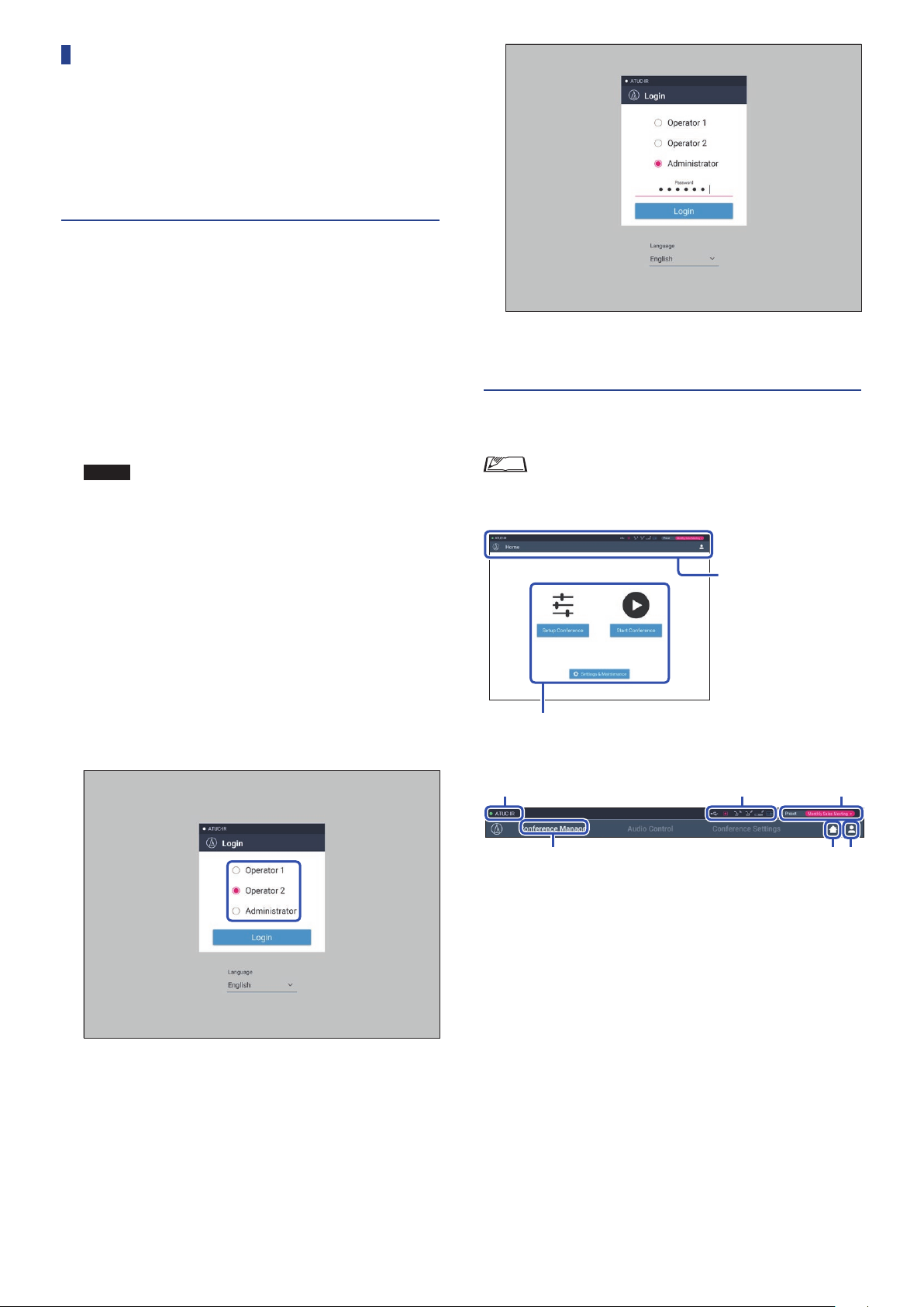
Starting up and logging in to Web Remote
Display the Web Remote login screen.
1
To log in to Web Remote from “Locate”:
(1) Follow steps 4 to 5 in “Setting up ‘Locate’” (➤page4).
Web Remote starts up and the login screen appears.
To log in to Web Remote without using “Locate”:
NOTICE
Select [Operator] or [Administrator], then click
2
• Check that the CU is connected to the same network
as the control device. When using a control device
with a network terminal, you can also directly
connect the CU to the control device using an
Ethernet cable (
Manual (Main Unit Edition)).
(1) From the CU Set Menu →
the IP address of the CU (
Instruction Manual (Main Unit Edition)).
(2) Run the browser and type the IP address you checked in
step (1) in the address bar.
Web Remote starts up and the login screen appears.
ATUC-50/ATUC-IR Instruction
➤
System Info
ATUC-50/ATUC-IR
➤
IP Address
→
[Login].
, check
After successfully logging in to Web Remote, the Home screen
appears.
About Web Remote Home screen
• Depending on the [Operator] access authority setting,
[Settings & Maintenance] may not appear on the Home
screen.
Header always displayed on
the screen.
Access each screen (
About the display items on the header:
page7).
➤
To change the language, click [▼] next to the language display
to expand the drop-down list and select the desired language.
The [Operator] access authority can be set from [System
Settings] → [User Access] → [Operator Access Settings]
page10).
(
➤
When a login password (
password on the password input screen.
page10) is already set, enter the
➤
③④ ②
①
Displays the screen name (e.g. Home).
①
Displays the recalled preset conference name (
②
some changes have been applied to the recalled preset, the preset
characters will appear in white color. Or, you can recall and save
presets.
Displays various indicators (
③
Manual (Main Unit Edition)). If any problem occurs, “▲”
appears below the corresponding indicator. Placing the cursor
over the indicator will display the pop-up screen which shows
the details of the problem.
Displays the name of the unit such as ATUC-50CU which is
④
being controlled via Web Remote.
Home button: Click to return to the Home screen.
⑤
Logout button: Click to display the currently logged-in authority
⑥
and the logout menu.
ATUC-50/ATUC-IR Instruction
➤
page30). If
➤
⑤ ⑥
6
Page 7
Configuring detailed system settings ([Settings & Maintenance])
From this menu, detailed system settings can be configured. Utilities
for troubleshooting and maintenance are also available.
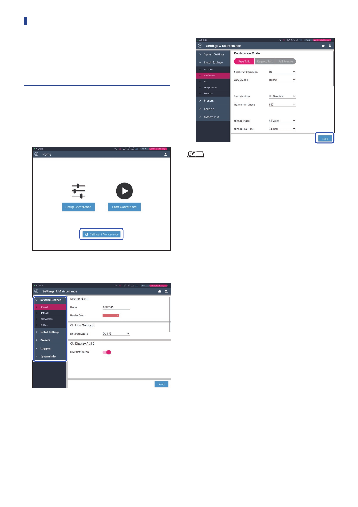
How to operate the [Settings & Maintenance] menu
On the Web Remote Home screen, click [Settings
1
& Maintenance].
Change the settings as necessary, then click
3
[Apply].
• The buttons displayed may vary depending on the screen.
• On screens where value changes are immediately applied,
such as on audio-related setting screens, the [Apply]
button may not appear.
From the 5 menu items on the left, click the item
2
you want to configure.
7
Page 8
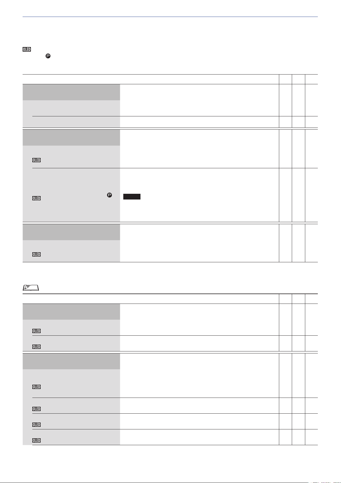
Menu item ① ([System Settings])
The setting values and default setting of each item which you can set from [System Settings] are as follows.
is the name of an item displayed on the CU display.
Items with
General Settings ([General])
are included in the preset settings.
Item name
Device Name
Name
Header Color
CU Link Settings
Link Port Setting
Link Port Set
Primary/Extension
CU Link Mode
CU Display/LED
Error Notification
CU Error Notice
Description and setting values (default settings are shown in
Displays the name of the unit being controlled via Web Remote.
ATUC-50CU / ATUC-IRCU
Set the header color that is displayed together with the device name.
Switch the terminal setting between CU LINK A/B terminals and DU CHAIN
C/D terminals.
, DU C/D
CU A/B
Set the dependency relationship of each CU (Primary/Extension) when
multiple CUs are cascade-connected.
Primary
, Extension Pass-Through, Extension Last Unit
NOTICE
• When using only one CU without a CU Link connection, be
bold
)
sure to set [CU Link Setting] to [Primary]. If [CU Link Setting]
is set to [Extension], we do not assume responsibility for any
unexpected consequences that may occur.
Set whether to show error notices on the CU’s display, and to have the LED on
the ATUC-MIC flash when an error occurs.
, Off
On
50CU IRCU IRCUDAN
✔ ✔ ✔
✔ ✔ ✔
✔ ✔ ✔
✔ - -
✔ ✔ ✔
Network Settings ([Network])
• After changing the network setting item(s), restart the CU to enable the setting values.
Item name
Network Configuration
Mode
Config Mode
Latency
Latency
Dante & Audio Port Settings
IP Config Mode (Primary)
IP Config Mode
IP Address (Primary)
IP Address
Subnet Mask (Primary)
Subnet Mask
Gateway Address (Primary)
Gateway Address
Description and setting values (default settings are shown in
Set the network configuration mode to match the environment.
Switched
Set the latency for Dante port.
250usec,
Specify the IP address-acquiring method.
Auto
Static: Specify static IP address. This enables you to specify the IP address,
subnet mask, and gateway address.
Displays the primary IP address.
Does not display when [IP Config Mode] is set to [Auto].
Displays the primary subnet mask.
Does not display when [IP Config Mode] is set to [Auto].
Displays the primary gateway address.
Does not display when [IP Config Mode] is set to [Auto].
, Redundant Audio, Split
500usec
: IP address is assigned by a DHCP server or the like.
, 1msec, 2msec, 5msec
bold
)
50CU IRCU IRCUDAN
- - ✔
- - ✔
- - ✔
- - ✔
- - ✔
- - ✔
8
Page 9
IP Settings (Secondary)
Do the secondary IP settings.
The settings for the various items are the same as for primary.
Only displayed when the network configuration [Mode] is set to [Redundant
Audio].
- - ✔
IP Control & Web Remote Port
Settings
IP Config Mode
IP Address
Subnet Mask
Gateway Address
Allow Discovery
IP Control Settings
Port Number
IP Ctrl Port No
Notification
IP Ctrl Ntfy
Audio Level Notification
Audio Level Ntfy
Multicast Address
M-cast Adrs
Multicast Port Number
M-cast Port No
Displayed with
Specify the IP address-acquiring method.
: IP address is assigned by a DHCP server or the like.
Auto
Static: Specify static IP address. This enables you to specify the IP address,
subnet mask, and gateway address.
Displays the IP address.
Does not display when [IP Config Mode] is set to [Auto].
Displays the subnet mask.
Does not display when [IP Config Mode] is set to [Auto].
Displays the gateway address.
Does not display when [IP Config Mode] is set to [Auto].
Enable/disable automatic detection from “Locate”.
, Off
On
Displays the IP control port number.
00001-65535 (
Enable/disable notification from the device during IP control.
On,
Off
Enable/disable notification of the audio level from the device when IP control
is enabled.
On,
Off
Specify multicast address.
0.0.0.0 - 255.255.255.255 (
Specify multicast port number.
00001-65535 (
IP Settings
17300
17000
when not using IRCUDAN.
)
225.0.0.100
)
)
✔ ✔ ✔
✔ ✔ ✔
✔ ✔ ✔
✔ ✔ ✔
✔ ✔ ✔
✔ ✔ ✔
✔ ✔ ✔
✔ ✔ ✔
✔ ✔ ✔
✔ ✔ ✔
Auto Mode Change When Network
Connection Lost
Enabled
Auto Mode Change
Hold time
Hold Time (Err)
NTP Settings
Enabled
NTP
Server Address
NTP Adrs
Port Number
NTP Port
Time Zone
Daylight Saving Time
DST
Start Date & Time
DST Start Date
DST Start Time
Automatically switches the conference mode to [Free Talk] Mode when a
network error occurs while operating in [Full Remote] Mode.
, Off
On
Set the time interval until [Full Remote] Mode switches to [Free Talk] Mode
after a network error occurs.
, 30, 40 sec
20
• During Web Remote control, the time interval may be longer by
up to 15 seconds.
Enable/disable NTP (Network Time Protocol).
On,
Off
Specify the NTP sever address.
0.0.0.0 - 255.255.255.255 (
Specify the NTP port number.
00001-65535 (
Specify the time difference to UTC (Coordinated Universal Time).
UTC –12:00 to +14:00; in 0:30 minute increments (
Enable/disable the daylight saving time option.
On,
Off
Set the start date and time for daylight saving time.
1/1 - 12/31 (
0:00 - 23:00; in 1 hour increments (
123
3/27
)
)
Empty
)
2:00
)
00:00
)
✔ ✔ ✔
✔ ✔ ✔
✔ ✔ ✔
✔ ✔ ✔
✔ ✔ ✔
✔ ✔ ✔
✔ ✔ ✔
✔ ✔ ✔
9
Page 10
End Date & Time
DST End Date
DST End Time
Infrared Settings ([Infrared])
Set the end date and time for daylight saving time.
1/1 - 12/31 (
0:00 - 23:00 (
10/30
2:00
)
)
✔ ✔ ✔
Item name
Description and setting values (default settings are shown in
Infrared Settings
IRDU to Detect on System Start
IRDU NoToDetect
Limit NOM to Enabled IR Bands
Limit NOM
Set the number of IRDU that are found when starting up.
50
Set whether to reflect IRDU NOM on NOM for conference settings also.
On,
IRDU Band
Active
Frequency
Enabled
IRDU Band
The indicator for the band that is active lights red.
Displays the frequency for each band.
Sets enable or disable for each band.
User Access Settings ([User Access])
Item name
Administrator Access Settings
Login Password
Admin.Pwd.Login
Admin.Password
Description and setting values (default settings are shown in
Enable/disable login password requirement for Administrator.
On,
Set a login password for Administrator.
4 to 8 alphanumeric characters (Empty)
Off
Off
bold
bold
)
)
50CU IRCU IRCUDAN
- ✔ ✔
- ✔ ✔
- ✔ ✔
- ✔ ✔
- ✔ ✔
50CU IRCU IRCUDAN
✔ ✔ ✔
✔ ✔ ✔
Operator 1 Access Settings
Edit Operator Name
Operator Name
Login Password
Operator Password
Opr.Pwd.Login
Opr.Password
Home Page
Start Conference
Setup Conference
Settings & Maintenance
Settings & Maintenance
CU Display Menu
System Settings
Set whether to change the name of Operator 1.
On,
Off
Set a name for the rights of Operator 1.
Operator 1
Enable/disable login password requirement for Operator 1.
, Off
On
Enable/disable login password requirement for Operator.
On,
Off
Set a login password for Operator.
4 to 8 alphanumeric characters (Empty)
Enable/disable function limitation for conference preparation ([Setup
Conference]) and conference operation and control ([Start Conference]).
, Limited
Full
Allow/restrict access to detailed settings ([Settings & Maintenance]). When
this item is set to [No], the [Settings & Maintenance] button will not appear
on the Home screen.
Yes,
No
Enable/disable access authority for detailed setting of each item ([Settings &
Maintenance] on Web Remote, Set on the CU display). Rights can be set for
each of the menus.
Only administrators can do system settings.
No
✔ ✔ ✔
✔ ✔ ✔
✔ ✔ ✔
✔ ✔ ✔
✔ ✔ ✔
✔ ✔ ✔
✔ ✔ ✔
✔ ✔ ✔
Install Settings
Yes,
No ✔ ✔ ✔
10
Page 11

Presets
Yes,
No ✔ ✔ ✔
Logging
System Info
Operator 2 Access Settings
Enabled
Edit Operator Name
Operator Name
Login Password
Home Page
Start Conference
Setup Conference
Settings & Maintenance
Settings & Maintenance
System Settings
Yes,
No ✔ ✔ ✔
, No
Yes
Sets enable or disable for Operator 2.
On,
Off
Set whether to change the name of Operator 2.
On,
Off
Set a name for the rights of Operator 2.
Operator 2
Enable/disable login password requirement for Operator 2.
On,
Off
Enable/disable function limitation for conference preparation ([Setup
Conference]) and conference operation and control ([Start Conference]).
, Limited
Full
Allow/restrict access to detailed settings ([Settings & Maintenance]). When
this item is set to [No], the [Settings & Maintenance] button will not appear
on the Home screen.
, No
Yes
Set the access authority in detailed setting ([Settings & Maintenance] on Web
Remote). Rights can be set for each of the menus.
Only administrators can do system settings.
No
✔ ✔ ✔
✔ ✔ ✔
✔ ✔ ✔
✔ ✔ ✔
✔ ✔ ✔
✔ ✔ ✔
✔ ✔ ✔
✔ ✔ ✔
Install Settings
Presets
Logging
System Info
CU Display Home Menu Settings
Level
Rec
Preset
Yes,
No ✔ ✔ ✔
Yes,
No ✔ ✔ ✔
Yes,
No ✔ ✔ ✔
, No
Yes
Limited to the initial menu displayed by OLED.
Rights can be set for each of the menus.
, No
Yes
, No
Yes
, No
Yes
✔ ✔ ✔
✔ ✔ ✔
✔ ✔ ✔
✔ ✔ ✔
11
Page 12
Utilities ([Utilities])
The following operations can be performed from [System Settings].
Item name
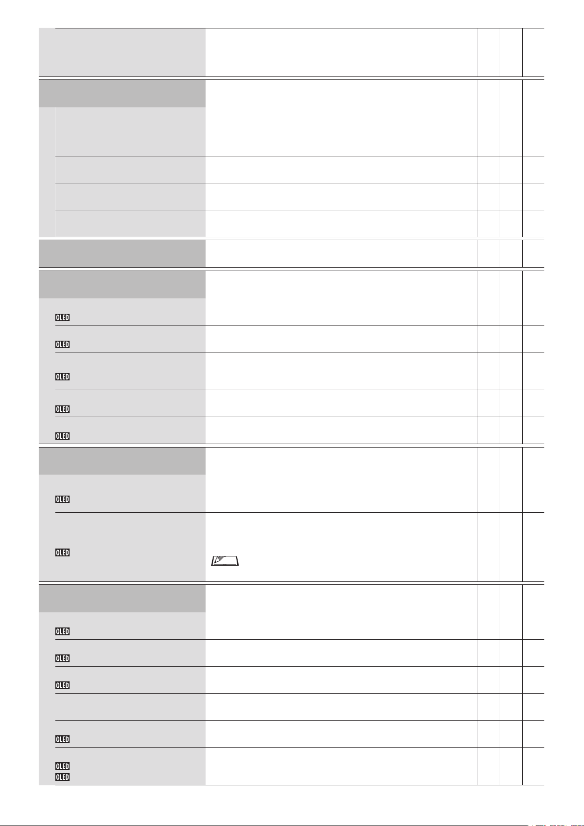
ATUC-50CU Firmware Update
Description and operation procedure
Updates the CU firmware.
②
Check the [Serial Number], [Device Name], and the current [Firmware
①
Version] on the screen to be sure that the displayed CU is the one you want
to update.
Click [Browse] to display the file select screen and select the version
②
upgrade file.
Click [Open] to start loading the file.
When the loading is complete, [Update] will be selectable. Click [Update].
③
After the confirmation message appears on the pop-up screen, click [Yes] to
④
perform the update.
When the update is complete, [Completed. Please turn power off.] will
appear.
Turn off the power of the CU to restart it.
⑤
50CU IRCU IRCUDAN
①
③
✔ - -
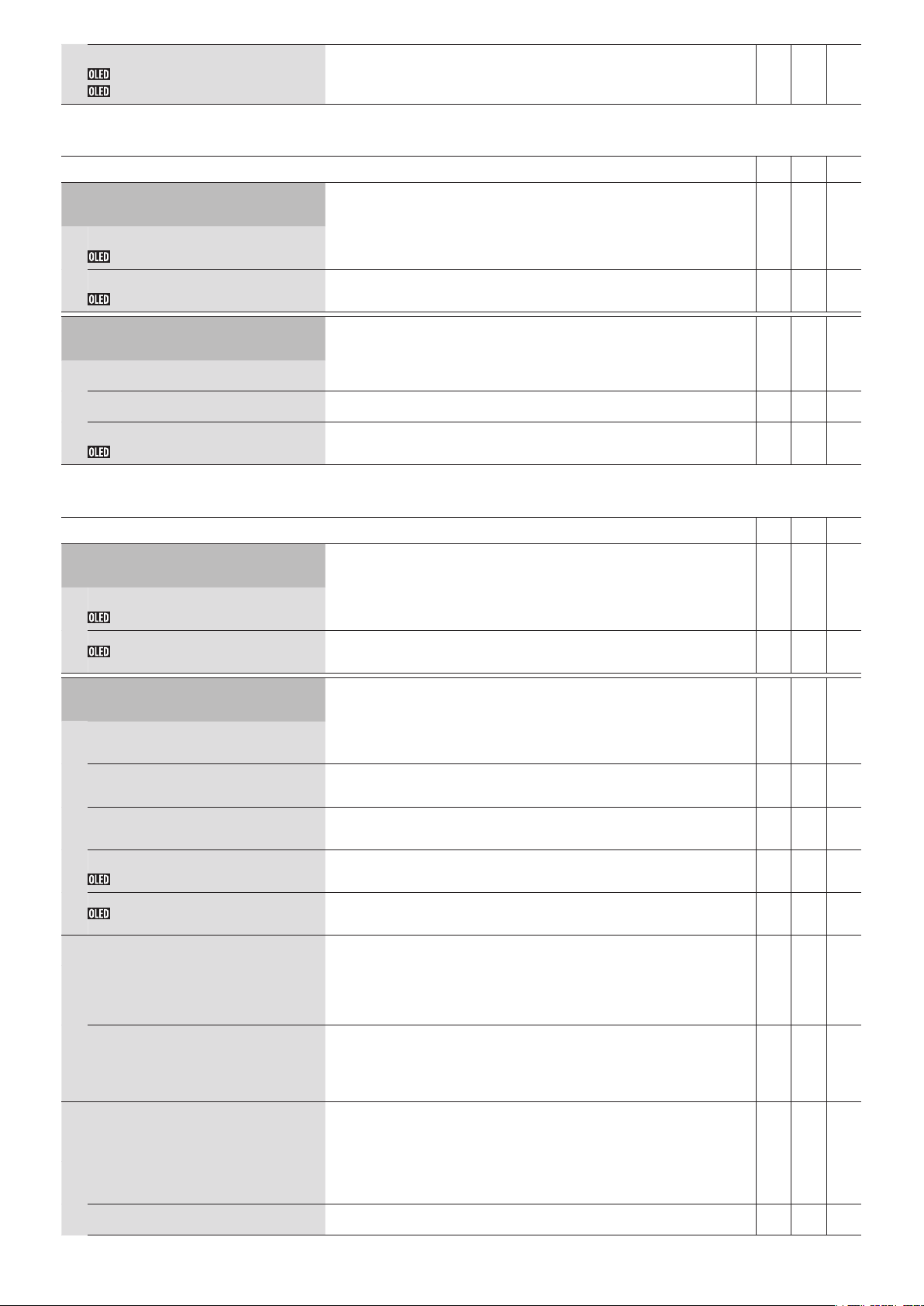
ATUC-IR Control Unit Firmware
Update
Updates the IRCU firmware (same as ATUC-50CU firmware update).
②
Check the [Serial Number], [Device Name], and the current [Firmware
①
Version] on the screen to be sure that the displayed CU is the one you want
to update.
Click [Browse] to display the file select screen and select the version
②
upgrade file.
Click [Open] to start loading the file.
When loading is complete, [Update] can be selected. Click [Update].
③
After the confirmation message appears on the pop-up screen, click [Yes] to
④
perform the update.
When the update is complete, [Completed. Please turn power off.] will
appear.
Turn off the power of the IRCU to restart it.
⑤
①
③
- ✔ ✔
12
Page 13

Updates the firmware related to infrared for IRCU.
①
ATUC-IR Infrared Firmware
Update
②
Check the [Serial Number], [Device Name], and the current [Firmware
①
Version] on the screen to be sure that the displayed CU is the one you want
to update.
Click [Browse] to display the file select screen and select the version
②
upgrade file.
Click [Open] to start loading the file.
When loading is complete, [Update] can be selected. Click [Update].
③
After the confirmation message appears on the pop-up screen, click [Yes] to
④
perform the update.
When the update is complete, [Completed. Please turn power off.] will
appear.
Turn off the power of the IRCU to restart it.
⑤
Updates the DU firmware.
③
- ✔ ✔
①
ATUC-50DU Firmware Update
②
Click the checkbox next to the [Serial Number], [Delegate Name], and the
①
current [Firmware Version] of each DU you want to update.
When you want to select all DUs, click [All] on the upper left of the DU
Firmware Update section on the screen.
Click [Browse] to display the file select screen and select the version
②
upgrade file.
Click [Open] to start loading the file.
When the loading is complete, [Update] will be selectable. Click [Update].
③
After the confirmation message appears on the pop-up screen, click [Yes] to
④
perform the update.
When the update is complete, [Completed. Please turn power off.] will
appear.
Turn off the power of the CU to restart it.
⑤
③
✔ ✔ ✔
13
Page 14

Updates the DUa firmware.
①
ATUC-50DUa Firmware Update
②
Click the checkbox next to the [Serial Number], [Delegate Name], and the
①
current [Firmware Version] of each DUa you want to update.
When you want to select all DUas, click [All] on the upper left of the DUa
Firmware Update section on the screen.
Click [Browse] to display the file select screen and select the version
②
upgrade file.
Click [Open] to start loading the file.
When the loading is complete, [Update] will be selectable. Click [Update].
③
After the confirmation message appears on the pop-up screen, click [Yes] to
④
perform the update.
When the update is complete, [Completed. Please turn power off.] will
appear.
Turn off the power of the CU to restart it.
⑤
Updates the IU firmware.
③
✔ ✔ ✔
ATUC-50IU Firmware Update
②
Confirm that [Serial Number], [Delegate Name], and the current [Firmware
①
Version] appear on the screen, and then select the check box on the left side
of the IU units that you want to update.
If you want to update all of the IUs, click [All] at the top right.
Click [Browse] to display the file select screen and select the version
②
upgrade file.
Click [Open] to start loading the file.
When the loading is complete, [Update] can be selected. Click [Update].
③
After the confirmation message appears on the pop-up screen, click [Yes] to
④
perform the update.
When the update is complete, [Completed. Please turn power off.] appears.
Turn off the power of the CU, and then restart it.
⑤
①
③
✔ ✔ ✔
14
Page 15

Updates the INT firmware.
①
ATUC-50INT Unit Firmware Update
Language Pack Installation
②
Click the checkbox next to the [Serial Number], [Delegate Name], and the
①
current [Firmware Version] of each INT you want to update.
When you want to select all INTs, click [All] on the upper left of the INT
Unit Firmware Update section on the screen.
Click [Browse] to display the file select screen and select the version
②
upgrade file.
Click [Open] to start loading the file.
When the loading is complete, [Update] will be selectable. Click [Update].
③
After the confirmation message appears on the pop-up screen, click [Yes] to
④
perform the update.
When the update is complete, [Completed. Please turn power off.] will
appear.
Turn off the power of the CU to restart it.
⑤
Installs the language pack.
Select the bank onto which you want to install the language pack.
①
Click [Browse] to display the file select screen and select the language file
②
you want to install.
Click [Install] to install the language pack.
③
When the installation is complete, [Completed. You will be automatically
logged out momentarily.] will appear and you will be automatically logged
out of Web Remote in 2 seconds.
To continue the operation, log in to Web Remote again.
③
✔ ✔ ✔
✔ ✔ ✔
Reset All Settings to Default
Reset All Dflt.
Restores 50CU/50DU/50IU/50INT/IRCU/IRCUDAN to the default settings
(this does not change the firmware version).
When [Do you really want to reset all settings to default?] appears, click
①
[Yes]. The confirmation message will appear again.
Click [Yes] to restore the default settings.
②
[Completed. Please turn power off.] will appear.
Turn off the power and restart the 50CU/IRCU/IRCUDAN.
③
✔ ✔ ✔
15
Page 16

Menu item ② ([Install Settings])
The setting values and default setting of each item you can set from [Install Settings] are as follows.
The item names with
Items with
are included in the preset settings.
CU Audio Settings ([CU Audio])
on the left are the names displayed on the CU display.
Item name
Input Settings
Mic/Line 1-2
Type
Input Type
Input Gain
Level
Level Meter
EQ Library
Low Cut
Phantom
Phantom Power
Can Be Muted
Mix to Floor
Mix to Language 1
(Only Mic/Line 1)
Mix to Language 2
(Only Mic/Line 2)
Description and setting values (default settings are shown in
Set the type and level for the Mic/Line audio inputs 1 and 2. 1 and 2 can be
configured individually.
Set the input type.
, Line +4dBu, Line 0dBV, Dante*
Mic
* Supported on IRCUDAN only.
Set the input gain of the Mic inputs (only when [Type] is set to [Mic]).
–24 to +20dB (
Set the Mic/Line input level. The level can be set individually for each input
type (Mic, Line, or Dante).
–∞, –120 to +10dB (
Displays the input level with a level meter.
Select the EQ pattern for the Mic/Line inputs. The EQ pattern can be selected
for each input type (Mic, Line, or Dante).
Flat
HH Dyn M: Dynamic Handheld Microphone for Male
HH Dyn F: Dynamic Handheld Microphone for Female
HH Cond M: Condenser Handheld Microphone for Male
HH Cond F: Condenser Handheld Microphone for Female
Lavalier M: Lavalier Microphone for Male
Lavalier F: Lavalier Microphone for Female
(IP Remote (*1))
BP892 M (*2), BP892 F (*2), AT898 M (*2), AT898 F (*2), AT899 M (*2),
AT899 F (*2), AT831 M (*2), AT831 F (*2)
*1: [IP Remote] appears when the equalizer is adjusted from [IP Remote]. [IP
Remote] cannot be selected from the drop-down list.
*2: Supported on IRCU and IRCUDAN only.
Enable/disable low frequency reduction for the Mic input.
, Off
On
Enable/disable phantom power (+48V).
On,
Off
Set whether to allow muting.
On,
Off
Set whether to mix the input sound to the floor channel.
, Off
On
Set whether to mix the voice being input with Language 1.
On,
Off
Set whether to mix the voice being input with Language 2.
On,
Off
0dB
)
0dB
)
bold
)
50CU IRCU IRCUDAN
✔ ✔ ✔
✔ ✔ ✔
✔ ✔ ✔
✔ ✔ ✔
✔ ✔ ✔
✔ ✔ ✔
✔ ✔ ✔
✔ ✔ ✔
✔ ✔ ✔
✔ ✔ ✔
✔ ✔ ✔
Aux
Type
Input Gain
Level
Level Meter
Input Type
Level
Configure the external input settings, such as audio type and level.
Set the external input type.
, Dante
Analog
Set the nominal level of the external input. Displayed when [Type] is set to
[Analog].
Line 0dBV
Set the input level of the external input.
–∞, –120 to +10dB (
Displays the input level on a level meter.
, –10dBV, –20dBV
)
0dB
16
- - ✔
✔ ✔ ✔
✔ ✔ ✔
✔ ✔ ✔
Page 17

Low Cut
Mix to Floor
Mix to Floor
Mix to Language 1
Mix to Language 2
Enable/disable low frequency reduction for the external input.
On,
Off
Set whether to mix the external input sound to the floor channel.
, Off
On
Set whether to mix the voice being input with Language 1.
On,
Off
Set whether to mix the voice being input with Language 2.
On,
Off
✔ ✔ ✔
✔ ✔ ✔
✔ ✔ ✔
✔ ✔ ✔
Return 1-2
Input Gain
Level
Level Meter
Low Cut
Group settings
Gain share
Bypass
FBS
On
Configure the level of the return input and the EQ pattern for the return input.
Set the nominal level of the return inputs.
, Line 0dBV
+4dBu
Set the input level of the return input.
–∞, –120 to +10dB (
Displays the input level on a level meter.
Enable/disable low frequency reduction for the return input.
On,
Off
Set whether to bypass the gain share.
Group 0: On,
Group 1 to Group 3: On, Off
Configure the feedback suppressor (FBS) settings. Selecting the check box sets
FBS of the corresponding [Audio Group] to [On] and makes the setting button
( ) selectable. Click the setting button ( ) to open the [Feedback
Suppression Settings] screen and configure advanced settings.
Group 0: On, Off
Group 1 to Group 3: On,
Off
0dB
)
Off
✔ ✔ ✔
✔ ✔ ✔
✔ ✔ ✔
✔ ✔ ✔
✔ ✔ ✔
✔ ✔ ✔
Feedback Suppression Settings
Frequency
Fixed
Reset
Detection
Response
Group 0: Mix to Floor
Group 1: Mix to Language 1
Group 2: Mix to Language 2
Group 3: Mix to Language 3
Detects feedback and displays the frequency with the notch filter applied.
When [Static] is set to [Off], the frequency dynamically changes according to
feedback detected.
*
* When [Static] is set to [On], the [Frequency] value is included in the preset
setting as the frequency of the static filter.
Lock the filter frequency by switching to the static filter.
On,
Off
Unlock all locked frequencies.
Configure the detection sensitivity of feedback frequency.
Lo w,
Configure the detection speed of feedback frequency.
Slow,
Mix the voice of [Group 0] with the Floor.
On
Mix the voice of [Group 1] with Language 1.
On
Mix the voice of [Group 2] with Language 2.
On
Mix the voice of [Group 3] with Language 3.
On
Mid
, Off
, Off
, Off
, Off
, High
Fast
✔ ✔ ✔
✔ ✔ ✔
✔ ✔ ✔
✔ ✔ ✔
✔ ✔ ✔
✔ ✔ ✔
✔ ✔ ✔
✔ ✔ ✔
✔ ✔ ✔
17
Page 18

Output Settings
Configure the output audio-related settings for each of OUTPUT terminals 1
to 4.
Output Destination 1 - 4
Source
PEQ
(Output 1 only)
PEQ Enabled
Frequency
(Band#1 - Band#8)
Gain
(Band#1 - Band#8)
Set the audio source to output.
Floor, Group 0, Group 1, Group 2, Group 3, Language 1, Language 2, Language
3
(The default settings are as follows:
Output 1:
Configure the parametric equalizer (PEQ) settings. Ticking the checkbox sets
PEQ of the corresponding output to [On] and makes the setting button (
selectable. Click the setting button ( ) to open the [PEQ Settings] screen
and then configure settings for each of bands 1 to 8.
Switch the PEQ setting between on and off.
On,
Off
Set the frequency for each of [Band#1] to [Band#8].
20Hz to 20kHz
(The default setting for each of [Band#1] to [Band#8] is as follows.
25, 63, 160, 400, 1000, 2500, 6300, 16000
Set the gain for each of [Band#1] to [Band#8].
–18dB to +10dB; adjustable in 0.5dB increments (
Floor
, Output 2:
Group 1
, Output 3:
)
Group 2
)
0dB
, Output 4:
Group 3
)
• For [Band#1], [Gain] is configurable only when [Filter Type] is
set to [LSH] or [PEQ].
• For [Band#8], [Gain] is configurable only when [Filter Type] is
set to [HSH] or [PEQ].
Set the Q value for each of [Band#1] to [Band#8].
✔ ✔ ✔
✔ ✔ ✔
)
✔ ✔ ✔
✔ ✔ ✔
✔ ✔ ✔
Q
(Band#1 - Band#8)
Filter Type
(Band#1)
Filter Type
(Band#8)
Reset
Reset All
DYN
(Output 1 only)
Enabled
Output 1 Level
Gain Reduction
Comp/De-Esser
Comp Threshold
Ratio
Attack Time
• For [Band#1] and [Band#8], the Q value is configurable only
when PEQ is enabled.
0.3 to 30 (10)
Set the filter type for [Band#1].
HPF, LSH,
Set the filter type for [Band#8].
LPF, HSH,
Restores specified band to the factory default settings.
Restores all bands to the factory default settings.
Configure the DYN (dynamics) settings. Ticking the checkbox sets DYN of
Output 1 to [On] and makes the setting button ( ) selectable. Click the
setting button ( ) to open the [Dynamics Settings] screen and then configure
various settings as follows.
Enable/disable the dynamics settings.
On,
Displays level of output 1 on a meter.
Displays audio compressed by the compressor in real time.
Changes the dynamics mode.
Comp
Configure the compressor threshold. The compressor functions only for audio
signals exceeding the specified value. Displayed when [Comp/De-Esser Mode]
is set to [Comp], for IRCU/IRCUDAN.
–60 to 0dB (
Set the compression ratio. Displayed when [Comp/De-Esser Mode] is set to
[Comp], for IRCU/IRCUDAN.
1.4:1,
Set the delay for the start of compression after audio signals exceed the
threshold. Displayed when [Comp/De-Esser Mode] is set to [Comp], for
IRCU/IRCUDAN.
0, 0.25, 0.5, 1, 2, 4, 8, 16, 32, 100msec (
PEQ
PEQ
Off
, De-Esser
–10
, 4:1, 6:1, 10:1, ∞:1
2:1
)
)
1msec
✔ ✔ ✔
✔ ✔ ✔
✔ ✔ ✔
✔ ✔ ✔
✔ ✔ ✔
✔ ✔ ✔
✔ ✔ ✔
✔ ✔ ✔
✔ ✔ ✔
✔ ✔ ✔
✔ ✔ ✔
✔ ✔ ✔
18
Page 19

Release Time
Gain
Limiter Threshold
Sensitivity
Center Frequency
Reduction
Level
Max Volume
(Output 1only)
Set the delay for the end of compression after audio signals fall back within the
threshold. Displayed when [Comp/De-Esser Mode] is set to [Comp], for
IRCU/IRCUDAN.
50, 100, 200, 400, 800, 1000, 2000msec (
Configure the compressor gain.
Displayed when [Comp/De-Esser Mode] is set to [Comp], for IRCU/
IRCUDA N.
–10 to +10dB (
Set the limiter threshold.
Audio signals exceeding the specified value will be cut out by the limiter.
Displayed when [Comp/De-Esser Mode] is set to [Comp], for IRCU/
IRCUDA N.
–60 to 0dB (
Set the sensitivity of the de-esser.
Displayed when [Comp/De-Esser Mode] is set to [De-Esser].
Soft,
Medium
Set the center frequency of the de-esser.
Displayed when [Comp/De-Esser Mode] is set to [De-Esser].
4.0kHz to 11.0kHz (
Set the reduction of the de-esser.
Displayed when [Comp/De-Esser Mode] is set to [De-Esser].
Soft,
Medium
Set the output level.
–∞, –120 to +10dB (
Set the maximum volume level.
–∞, –120 to
0dB
)
–10
, Hard
, Hard
+10dB
)
6.0kHz
–40dB
)
)
400msec
)
✔ ✔ ✔
✔ ✔ ✔
✔ ✔ ✔
✔ ✔ ✔
✔ ✔ ✔
✔ ✔ ✔
✔ ✔ ✔
✔ ✔ ✔
19
Page 20

Conference Settings ([Conference])
Select the conference mode according to the conference operation and control method and configure detailed settings.
• The following setting items are also included in [Setup Conference] where you can configure the same settings.
• [Free Talk]
In this mode, attendees can talk when the (talk) button is pressed or when their DUs automatically detect their voices.
• [Request Talk]
In this mode, attendees request to talk by pressing the (talk) button on the DU and will be permitted to talk by the steering committee.
The steering committee can also reject the talk request.
To operate the conference in this mode, connect the CU to a control device such as a computer.
• [Full Remote]
In this mode, utterances are totally controlled via Web Remote. The DU (talk) button operations will be disabled.
To operate the conference in this mode, connect the CU to a control device such as a computer.
Item name
Conference Mode
Conference Mode
Number of Open Mics(*1)
NOM
Auto Mic OFF(*1)
Auto Mic Off
Override Mode (Free Talk
Mode)(*1)
Override Mode (Request Talk
Mode)(*1)
Override Mode (Full Remote
Mode)(*1)
Maximum in Queue(*1)
Max Queue
Mic ON Trigger / Mic ON Trigger
for Priority(*1)
MicON Trigger
Mic ON Hold Time(*1)
MicON Hold Time
Description and setting values (default settings are shown in
Select the conference mode and configure detailed settings
Select the conference mode.
Free Talk
Set the maximum number of the DUs (speakers) that can talk at the same time.
10
Set the time interval until the microphone automatically turns off after the
speaker stops talking (after a soundless state is detected).
5 to 60sec, Off; adjustable in 5-second increments (
Select the override method(*2) in [Free Talk] Mode.
No Override
Select the override method(*2) in [Request Talk] Mode.
FIFO
Select the override method(*2) in [Full Remote] Mode.
FIFO
Set the maximum number of DUs that can be in talk standby mode at the same
time.
0 to 150 (
Set whether to manually turn on the microphone by pressing the
button or to automatically turn on the microphone when a voice is detected,
for all DUs.
When [Conference Mode] is set to [Request Talk] or [Full Remote], this item
switches to [Mic ON Trigger for Priority], which is the setting for priority
DUs.
All Button Toggle
* The setting value that is displayed is based on the settings for each DU. When
Specify the time until the microphone automatically turns off on DUs where
[Mic ON Trigger] is set to [Voice]. The microphone automatically turns off
when the attendee keeps silent for the specified time.
1.0 to 10.0 seconds; adjustable in 0.5-second increments (
, Request Talk, Full Remote
to 1
)
Off
, FIFO, LIFO
, LIFO
, LIFO
50 units
all DUs are set to the same method to turn on the microphone, that mode is
displayed. If there is a mixture of modes, then [Individual] appears. However,
[Individual] cannot be executed as a function.
)
, All Push to Talk, All Voice (Individual*)
)
bold
(talk)
2.5 seconds
)
50CU IRCU IRCUDAN
✔ ✔ ✔
✔ ✔ ✔
✔ ✔ ✔
✔ ✔ ✔
✔ ✔ ✔
✔ ✔ ✔
✔ ✔ ✔
✔ ✔ ✔
✔ ✔ ✔
Priority Mode
Interrupt Option(*1)
Set the operation when the user of the priority DU (➤page23) presses and
holds the DU
Set whether the priority DU user cuts short or temporarily mutes other DU
users by pressing and holding the
, Mute
Cut
(talk) button.
(talk) button.
20
✔ ✔ ✔
Page 21

SFX 1-3 Setting
Name
It is possible to replay any audio file, such as a buzzer or chime that has been
saved to a USB device (mass storage device).
A maximum of 3 audio files can be registered and assigned to the 3 buttons
displayed on the [Audio Control] screen. (➤page34).
Specify names for buttons to which audio files are assigned.
(Up to 15 characters)
SFX1 to 3
Follow the procedure below to register audio files.
Copy audio files (up to 30 files) that you want to play to the root directory
①
of a USB device (mass storage device)
Connect the USB device (mass storage device) to CU
②
Select an audio file from the [Source] pulldown list
③
Playback(*1)
✔ ✔ ✔
Source
WAV
Sampling frequency 48kHz
✔ ✔ ✔
Bit rate 32-320kbps
MP3(*2)
Sampling frequency 48kHz
Maximum file size 2GB
Maximum number of files 30files
Data length 16bit, 24bit
*1 Supported file systems: FAT16/FAT32
*2 Supported on MPEG-1 Audio Layer-3 only.
Floor Output Sound when all
Mics Muted
Select the source to play when DU mics are turned off.
Source
Level
*1 About setting changes
Settings can be changed when all DUs are in the Talk OFF state.
*2 About the override setting
Specify which DU (speaker) is cut short and which DU’s request will be permitted if the number of DUs (speakers) who can talk at the same time has
already reached the specified maximum limit ([Number of Open Mics]) and more attendees press the
, Mic/Line 2, Chime*, Pink Noise
Off
* Supported on IRCU and IRCUDAN only.
Select the volume of the source to play when DU mics are turned off.
–∞, –120 to +10dB (
0dB
)
(talk) button.
✔ ✔ ✔
✔ ✔ ✔
FIFO (First-In First-Out):
Cuts short the speaker who was least recently permitted to talk and permits the person who has just pressed the (talk) button to talk.
LIFO (Last-In First-Out):
Cuts short the speaker who was most recently permitted to talk and permits the person who has just pressed the (talk) button to talk.
No Override:
(unselectable while in [Request Talk] Mode or [Full Remote] Mode)
The person who has just pressed the (talk) button will be in talk standby and will be permitted to talk when his/her turn comes.
DU Settings ([DU/IU])
Item name
Global DU/IU Settings
Speaker Level
DU SP Output Lvl
Monitor Channel Lock
Monitor CH Lock
Voice Detection Sensitivity
VoiceDetectSens
Auto relative to Mic2 Input
Auto to Mic2 In
Description and setting values (default settings are shown in
Configure DU common settings. Basically apply the common setting of the
DUs to the IU/IRDUs, as well.
Set the speaker output level.
0 to 20 (10)
Switch the lock function for the monitor channel selection buttons.
On,
Off
Set the detection level when voices are detected in automatic mode.
–5, –4, –3, –2, –1, 0, 1, 2, 3, 4, 5 (0)
The voice detection level automatically adjusts to the level at which
background noise is picked up by the MIC2 input terminal.
On,
Off
bold
)
50CU IRCU IRCUDAN
✔ ✔ ✔
✔ ✔ ✔
✔ ✔ ✔
✔ ✔ ✔
21
Page 22

ATUC-IRDU Settings
Multifunction LED
Talk ON
Queuing
Cut/Mute
Permit Next
Low Battery (LED Blink)
ATUC-50DU Settings
DU Talk LED Color(*1)
Talk ON
Queuing
Set the color of IRDU Multifunction LEDs for each function; Talk ON,
Queuing, Cut/Mute, and Permit Next.
Select and set the color of the Multifunction LED when someone is talking.
9 colors (
Select and set the color of the Talk LED when waiting to talk.
9 colors (
Select and set the color of the LED when a priority DU causes cut/mute.
10 colors (
Select and set the color of the LED when talking is permitted in Request Talk
mode.
10 colors (
Set whether to have the LED blink when the battery is low for IRDU batteries 1
and 2.
Battery 1:
Battery 2:
Set the LED colors for DUs (talk). (Except for IUs)
Set the (talk) LED color when talking.
10 colors (
Set the (talk) LED color when waiting to talk.
10 colors (
)
Red
Green
Yellow
Blue
Off
On
Red
Green
)
)
)
)
)
- ✔ ✔
- ✔ ✔
✔ ✔ ✔
ATUC-50IU Settings
Non-Priority IU GPIO 0
Individual DU/IU Settings
Sort list
Device icons
LED
Talk
Priority
Serial#
Delegate Name
Audio Group
Color
Operations for the DU (*3)
Set the GPIO of the IUs with no priority to 0.
, Self Mute
GPIO 0
Display the DU/IU/IRDU in a list, and then do individual settings.
Sorts the list by "Active", "Wired Function Priority", or "Wireless Function
Priority".
50CU supports "Active" only.
Icons that indicate the categories of the units connected to the system.
Check that the DU/IU/IRDU LEDs light up.
The rear LED and
ATUC-M blink while the corresponding icon on the screen is lit.
Check the talk status of each DU.
Enable/disable the DU/IU/IRDU priority settings (*2). You can turn on
priority for up to one unit fewer than the maximum number of simultaneous
speakers (➤ page20).
On,
Off
Displays the serial number.
Assign names (e.g. attendee names) to differentiate DUs/IUs/IRDUs.
You can use up to 30 characters (10 2-byte characters). (
The output signals from each DU/IU/IRDU can be categorized into 4 audio
groups. One or more audio groups can be selected as output destination(s),
and furthermore, the output terminal on the CU can be specified for each
group. (➤pages18)
Group 0
Select a color for the rear LED from the drop-down list.
10 colors (
Select one or more DUs/IUs/IRDUs from the list and perform the following
operations.
Edit Detail Settings, Copy, Identify, Select all, Deselect all, Delete
, Group 1, Group 2, Group 3
Red
(talk) LED on the DU as well as the ring LED on the
8-digit number
)
)
✔ ✔ ✔
✔ ✔ ✔
✔ ✔ ✔
✔ ✔ ✔
✔ ✔ ✔
✔ ✔ ✔
✔ ✔ ✔
✔ ✔ ✔
✔ ✔ ✔
✔ ✔ ✔
✔ ✔ ✔
22
Page 23

*1: About setting changes
Settings can be changed when all DU/IUs are in the Talk OFF state.
*2: About the priority setting
Priority DU/IU(s) are given authorization to do the following:
• Talk anytime
• Cut short or temporarily mute all other attendees simultaneously
It is assumed that the priority setting is enabled on DU/IUs that are used by people in charge of the proceedings of a conference, such as a chairman
or company directors who are permitted to talk anytime.
*3: DU/IU operations
②
①
Click ① of the DU/IU(s) for which you want to adjust the settings.
1
A check mark will be inserted in the checkbox.
You can also select multiple DU/IUs and simultaneously change settings of the selected DU/IUs.
Click ② to display the drop-down list and proceed to the following operations.
2
• The number displayed on ② is the number of selected DU/IUs.
Edit Detail Settings:
Simultaneously configure detailed settings for the selected DU/IUs (refer to the [DU/IU Detail Settings] table below).
When multiple DU/IUs are selected, setting items for which the current values differ among the DU/IUs will be grayed out.
• Items which remain grayed out: Setting values of each DU/IU are retained.
• Grayed out items which become selectable after operation: Setting values of all selected DU/IUs will be changed to the displayed values.
Copy:
Copies settings of the selected DU/IU and pastes to other DU/IUs.
Select 1 DU from which you want to copy settings.
①
Select [Copy] from the drop-down list.
②
All checkboxes, icons and the like except DU/IU select checkboxes will be unselectable.
Select the DU/IU(s) to which you want to paste the settings.
③
Press the [Paste] button.
④
Delete:
Deletes the selected DU/IU(s) from the list. Only DU/IU(s) in a disconnected state can be deleted.
Select all:
Selects all DU/IUs.
Deselect all:
Deselects all DU/IUs.
• Depending on the DU/IU selection state, some items above may not appear.
23
Page 24

DU/IU Detail Settings ([DU/IU Detail Settings])
Item name
Microphone
Level
Input Gain
AGC
EQ Library
Mic ON Trigger
Phantom Power
Description and setting values (default settings are shown in
Configure microphone-related settings.
Displays the level with a level meter.
Set the microphone input gain.
–20dB to +20dB (
Enable/disable AGC (Automatic Gain Control).
On,
Off
NOTICE
• When operating the system with [AGC] set to [On], set the
0dB
)
bold
)
[Mode When Talk ON] setting under [Speaker] to
[Attenuation] or [Off].
Set the EQ pattern for the microphone input.
, Neutral Male, Neutral Female, Clear Male, Clear Female, Warm Male,
Flat
Warm Female, AT ES Series, AT UniPoint, (IP Remote*)
* [IP Remote] appears when the equalizer is adjusted from [IP Control
Settings]. [IP Remote] cannot be selected from the drop-down list.
Set whether to manually turn on the microphone by pressing the (talk)
button or to automatically turn on the microphone when a voice is detected.
All Voice,
Enable/disable the phantom power supply to the microphone.
On
All Button Toggle
, Off
, All Push to Talk
IRDU 50DU 50IU
✔ ✔ ✔
✔ ✔ ✔
✔ ✔ ✔
✔ ✔ ✔
✔ ✔ ✔
✔ ✔ ✔
Speaker
Enabled
Mode When Talk ON
Audio Group
Assign
Default mode
Rear LED Color
(This is a setting item only for DUs.)
ON
Talk ON / Queuing
Talk OFF
Enable/disable the DU/IU speaker.
, Off
On
The attendee switches speaker mode while talking. When [Attenuation] is
selected, the ducking feature lowers the volume level by –20dB (this item
appears only when the speaker is enabled).
On,
Attenuation
The CU categorizes the audio signals transmitted from the DU/IUs and then
outputs the signals to the specified channels.
Up to 4 channels can be specified for each DU. Multiple groups can be selected
and output channels can be selected for each group (➤page18).
Group 0
Set the channel when DU starts up and when monitor channel is fixed.
Set the LED on the back to on or off.
Displayed when using IRCU/IRCUDAN.
On
Select a color for the rear LED from the drop-down list.
10 colors (
Set how Talk OFF is lit.
Off
, Group 1, Group 2, Group 3
, Off
, Dim
Red
, Off
)
✔ ✔ ✔
✔ ✔ ✔
✔ ✔ ✔
✔ ✔
(DUa only)
✔ ✔ -
✔ ✔ -
✔ ✔ -
-
Two Person Mode
On, Off
Set whether to allow use by two people.
* When on, priority automatically turns off.
On,
Off
24
✔ - -
Page 25

Priority
Enabled
Can Cut/Mute
Can be Cut/Muted
Boot up Talk On
Left Button Function Assign
GPI Pin Settings
(This is a setting item only for IUs.)
GPI 0 - 7
Configure the priority (➤page23) settings.
Enable/disable the priority setting. The maximum number of DUs that can be
designated as priority DU is 1 unit less than the maximum number of DUs
(speakers) that can talk at the same time (➤page20).
On,
Off
Set whether the priority DU user can temporarily cut short/mute other DUs.
, Off
On
Set whether the priority DU are temporarily cut short/muted by other DUs.
On,
Off
The mic turns on when the DU is started up.
Displayed when using IRCU/IRCUDAN.
On,
Off
Select the function to assign to the left button.
Cut/Mute
Set the function to assign GPI ports 0 to pin 7.
GPI x
Self-Mute: The unit mutes the voice from its own microphone (self-mutes)
Permit Next: Permits the DU on the top of the list to talk
Undo Permit Next: Undo the previous permission to talk
Master Volume Up: Turns up the volume for the master level
Master Volume Down: Turns down the volume for the master level
Recall Preset 1: Selects and recalls preset 1
Recall Preset 2: Selects and recalls preset 2
Recall Preset 3: Selects and recalls preset 3
Recall Preset 4: Selects and recalls preset 4
Recall Preset 5: Selects and recalls preset 5
Recall Preset 6: Selects and recalls preset 6
Recall Preset 7: Selects and recalls preset 7
Recall Preset 8: Selects and recalls preset 8
REC Start: Starts recording
REC Stop: Stops recording
SFX 1: Plays and stops SFX 1
SFX 2: Plays and stops SFX 2
SFX 3: Plays and stops SFX 3
Mic/Line 1 Mute: Mutes Mic/Line 1
Mic/Line 2 Mute: Mutes Mic/Line 2
, Permit Next
(x is any port number 0 to 7): use as a general purpose input pin
✔ ✔ ✔
✔ ✔ ✔
✔ ✔ ✔
✔ ✔ ✔
✔ - -
- - ✔
25
Page 26

GPO Pin Settings
(This is a setting item only for IUs.)
GPO 0 - 7
Set the function to assign GPO port 0 to port 7.
(x is any port number 0 to 7): use as a general purpose output pin
GPO x
Self-Mute Indicator: Indicates when self-muted
Lit: Self-muted
Cut/Mute Indicator: Indicates when a mic is disconnected or muted
Lit: Muted Blinking: Cut
Preset 1 Indicator: Indicates when preset 1 is called
Lit: Call done Blinking: Selecting
Preset 2 Indicator: Indicates when preset 2 is called
Lit: Call done Blinking: Selecting
Preset 3 Indicator: Indicates when preset 3 is called
Lit: Call done Blinking: Selecting
Preset 4 Indicator: Indicates when preset 4 is called
Lit: Call done Blinking: Selecting
Preset 5 Indicator: Indicates when preset 5 is called
Lit: Call done Blinking: Selecting
Preset 6 Indicator: Indicates when preset 6 is called
Lit: Call done Blinking: Selecting
Preset 7 Indicator: Indicates when preset 7 is called
Lit: Call done Blinking: Selecting
Preset 8 Indicator: Indicates when preset 8 is called
Lit: Call done Blinking: Selecting
REC Indicator: Indicates when recording
Blinking: Recording
SFX 1 Indicator: Indicates when SFX 1 is playing back
Blinks: Playing back SFX 1
SFX 2 Indicator: Indicates when SFX 2 is playing back
Blinks: Playing back SFX 2
SFX 3 Indicator: Indicates when SFX 3 is playing back
Blinks: Playing back SFX 3
Undo Permit Next Indicator :
Indicator for when the previous permission to talk is undone
Mic/Line 1 Mute Indicator :
Indicator for when Mic/Line 1 is muted
Mic/Line 2 Mute Indicator :
Indicator for when Mic/Line 2 is muted
- - ✔
Voting Units Settings
Button & LED 1 to 5
Assign the functions that can be assigned to VUs.
This can only be set when a DUa, for which Priority is set to on, is connected.
IP Control
Permit Next: Permits the requesting speaker on the top of the list to talk
Undo Permit Next: Undoes the previous permission to talk
Master Vol Up: Increases the volume of the master level
Master Vol Down: Decreases the volume of the master level
Preset 1 Recall: Recalls preset 1
Preset 2 Recall: Recalls preset 2
Preset 3 Recall: Recalls preset 3
Preset 4 Recall: Recalls preset 4
Preset 5 Recall: Recalls preset 5
Preset 6 Recall: Recalls preset 6
Preset 7 Recall: Recalls preset 7
Preset 8 Recall: Recalls preset 8
SFX 1: Plays or pauses SFX 1
SFX 2: Plays or pauses SFX 2
SFX 3: Plays or pauses SFX 3
: Button operation (when pressed) information, and how the
indicators light are controlled by IP
(See the IP Control Protocol Specifications for details.)
- ✔
(DUa only)
-
26
Page 27

Interpretation Settings ([Interpretation Settings])
Item name
Interpretation Settings
Interpretation Mode
Easy Mode
Language Name
Group 1
Group 2
Group 3
Interlock Mode
Description and setting values (default settings are shown in
Set the interpretation mode.
2 Languages,
Automatically toggles the voice on the floor with the voice of the interpreter.
When [On] is set, for example, the voice on the floor is automatically output to
language group 1 by putting INTs that are outputting an interpreter’s voice to
language group 1 on All Talk OFF.
On,
Off
Set the Language Name for Audio Group 1.
(Up to 15 characters)
Language 1
Set the Language Name for Audio Group 2.
(Up to 15 characters)
Language 2
Set the Language Name for Audio Group 3.
(Up to 15 characters)
Language 3
NOTICE
3 Languages
• Displayed only when “3 Languages” is selected in Interpretation
bold
)
Mode.
Set Interlock Mode for interpretation units with the same settings.
No Interlock,
Interlock, Combine
50CU IRCU IRCUDAN
✔ ✔ ✔
✔ ✔ ✔
✔ ✔ ✔
✔ ✔ ✔
✔ ✔ ✔
✔ ✔ ✔
✔ ✔ ✔
INT Unit Settings
(Max. 6 units)
Connected INT Units
LED
Serial#
Interpretation Languages
Operations of the INT Unit Settings
(*1)
Configure settings individually for each INT.
Display setting information of all INTs connected to the system. You can check
and change settings.
Check that the INT LED lights up.
The rear LED on the INT, ring LED on the ATUC-M, and (talk) LED blink
while the corresponding icon on the screen is lit.
Displays the serial number.
Select the pattern for the languages to be interpreted. The language name
selected from the selection list appears in [Language Name].
Additionally, patterns and the number of languages depend on the setting
values of [Interpretation Mode].
If the Interpretation Mode is 2 Languages:
1: Language 1 ↔ 2: Language 2
2: Language 2 → 1: Language 1
If the Interpretation Mode is 3 Languages:
1: Language 1 ↔ 2: Language 2
2: Language 2 ↔ 3: Language 3, 1: Language 1 → 2: Language 2,
2: Language 2 → 1: Language 1, 1: Language 1 → 3: Language 3,
3: Language 3 → 1: Language 1, 2: Language 2 → 3: Language 3,
3: Language 3 → 2: Language 2
, 1: Language 1 → 2: Language 2,
, 1: Language 1 ↔ 3: Language 3,
✔ ✔ ✔
✔ ✔ ✔
✔ ✔ ✔
✔ ✔ ✔
✔ ✔ ✔
27
Page 28

*1: About Operations of the INT Unit Settings
②
①
Click ① the INT(s) for which you want to change the settings.
1
A check mark appears in the checkbox.
You can also select multiple INTs and simultaneously change settings of the selected INTs.
Click ② to display the drop-down list and proceed to the following operations.
2
• The number shown on ② indicates the number of the currently selected INTs.
Edit Detail Settings:
Configure the detailed settings of the INT(s) you selected (refer to the table below on detailed settings for INTs [INT Unit Detail
Settings]). When multiple INTs are selected, setting items for which the current values differ among the INTs are grayed out.
• If items remain grayed out: Setting values of each INT are retained.
• If grayed out items become selectable after operation: Setting values of all selected INTs will be changed to the displayed values.
Select all:
Selects all INTs.
Deselect all:
Deselects all INTs.
Delete:
Deletes the selected INT(s) from the list. Only INT(s) that have been disconnected can be deleted.
• Depending on the INT selection state, some items above may not appear.
• There is no function to copy the settings of an INT to other INTs.
INT Unit Detail Settings ([INT Unit Detail Settings])
Item name
Microphone
Level Meter
Description and setting values (default settings are shown in
Configure microphone-related settings for the INT(s).
Displays the level with a level meter.
bold
)
Input Gain
AGC
EQ Library
Phantom Power
Set the microphone input gain.
–20 to +20dB (
Enable/disable AGC (Automatic Gain Control).
On,
Off
Set an EQ pattern to be applied to the microphone input.
Flat, Neutral Male, Neutral Female, Clear Male, Clear Female, Warm Male, Warm Female, AT ES
Series, AT UniPoint, (IP Remote*)
* [IP Remote] appears when the equalizer is adjusted from [IP Control Settings]. [IP Remote]
cannot be selected from the drop-down list.
Enable/disable the phantom power supply to the microphone.
, Off
On
0dB
)
28
Page 29

Recording Settings ([Recorder])
NOTICE
• Recording settings can be configured only when recording stops.
Item name
USB Recorder Settings
Record File Format
Rec Format
Recording Quality
Number of Recording Channels
(WAV)
No.of Rec CH
Number of Recording Channels
(MP3)
No.of Rec CH
Recording Source
Track1, Track2, Track3, Track4
Rec Source CH1-CH4
Auto Track
Rec Filename Prefix
Filename Prefix
Description and setting values (default settings are shown in
Select the conference recording format.
, MP3
WAV
Set the bit rates for recording speech in MP3 format.
64, 128, 192, 256,
Set the number of recording audio channels when the recording format is WAV.
1 to
4
Set the number of recording audio channels when the recording format is MP3.
1 to
2
Set the recording source for each channel.
, Group 0, Group 1, Group 2, Group 3 , Language 1, Language 2, Language 3, Remote Lang. 1,
Floor
Remote Lang. 2, Mic/Line 1, Mic/Line 2, Mic/Line 1&2 Mix
Split audio files by the specified time while recording or disable this function.
, 15 min, 30 min, 1 hour, 2 hours
Off
Specify prefix for recorded audio files.
Up to 30 characters can be used. (Some characters cannot be used (➤ATUC-50/ATUC-IR
Instruction Manual (Main Unit Edition)). The default setting is
320
kbps
bold
)
atuc-50
.)
29
Page 30

Accessing your presets ([Presets])
Log management ([Logging])
Recall, save, import/export presets.
Click ○ on the right side of the preset number
1
you want to select.
will light red and the field of the selected preset will be
○
highlighted in light blue.
Click the operation you want to perform.
2
The selected operation will be executed.
Export (
Exports the preset data to an external device. From the pop-up
window, select the folder where you want to export the data.
Export Presets
):
Configure the system log settings. You can also download the log
file.
Enabled (
Set whether to save the system log. (On, Off)
Output Destination (
Set whether to export the log file to a USB device (mass storage
device). (
Log File:
Select the download destination and download the log file to the
specified destination.
Logging
Internal
):
, USB)
Destination
):
Import (
Imports the preset data that was exported to an external device.
From the pop-up window, select the preset data file you want to
import.
Set the “Wired DU Preset Save/Recall” item.
3
You can set whether to link the preset registration by topology
or serial number. (
Import Presets
• To edit the preset name, click the name. You can use up
to 30 characters.
• If you want to do settings to call a specific preset while
the system is starting, select that preset’s number.
Topology
):
, Serial Number)
Displaying the system information ([System Info])
Display the system information such as the firmware version,
various network setting statuses, and unit serial numbers.
30
Page 31

Preparing for conferences ([Setup Conference])
To handle many different types of conferences using a conference
system, it is recommended to preset multiple types of conference
settings. Basic conference preparation can be carried out simply by
recalling the preset that best suits an upcoming conference.
Up to 8 conference settings can be preset.
You can also change settings saved on the recalled preset to suit the
upcoming conference.
Prepare for the upcoming conference in 3 steps by utilizing the
preset function.
Recalling the preset ([Recall Preset])
1
Recalls the preset and then displays the [Conference Settings]
screen.
The [Recall Preset] screen will appear if you click [Setup
Conference] on the Home screen (
For starting a conference using the most recently used conference
setting (Current Settings) or one of the preset settings, follow the
procedure below to display the [Conference Manager] screen.
On the [Recall Preset] screen, select [Current
1
page6).
➤
Settings] or your desired preset and then click
[Next].
Changing the conference settings
2
([Conference Settings])
Change the settings as necessary and then click
1
[Next].
Saves the settings and displays the [DU/IU Settings] screen.
• To configure settings based on the current setting, select
[Current Settings].
31
Page 32

Adjusting the DU/IU settings ([DU/IU
3
Settings], [DU/IU Detail Settings])
Configure DU/IU settings and DU/IU detail settings.
Change the settings as necessary.
1
To configure detail settings:
Proceed to step 2.
To finish settings without configuring detail
settings:
Click [Next], then click [Done].
From the drop-down list ②, click [Edit Detail
3
Settings].
Displays the [DU/IU Detail Settings] screen and enables you to
configure DU/IU detail settings.
Configure DU/IU detail settings and click [Apply]
4
to apply the changes.
Returns to the [DU/IU Settings] screen.
• For details on each setting item, refer to the [DU/IU
Settings] item table (
Click ① of the DU/IU(s) for which you want to
2
page21).
➤
change the settings, to enter a ✔ mark.
②
①
• For details on each setting item, refer to the [DU/IU
page24).
➤
page24).
➤
Detail Settings] item table (
• When multiple DUs/IUs are selected, setting items for
which the current values differ among the DUs/IUs will
be grayed out. These setting items cannot be adjusted.
• The [Phantom Power] setting for DUs/IUs can be
configured from [Settings & Maintenance] → [Install
Settings] → [DU/IU] → [Individual DU/IU Settings] →
[Connected DUs/IUs] → [Edit Detail Settings] → [DU/
IU Detail Settings] (
Click [Done] on the bottom right of the screen.
5
The [Conference Manager] screen under [Start Conference]
appears (
the conference.
page33) indicating that the system is ready to start
➤
• From the drop-down list ②, you can select/unselect all
DU/IUs.
• The number shown on ② indicates the number of the
currently selected DU/IUs.
• ① and ② will not appear if the currently logged in
Operator is not permitted to access these settings.
32
Page 33

Operating and controlling conferences ([Start Conference])
The [Start Conference] screen is displayed by clicking [Start
Conference] (
from [Setup Conference].
Operate and control a conference underway. You can also change
detailed settings of the conference underway.
Using the tabs on the upper side of the screen, conference mode can
be switched between the following 3 modes.
[Conference Manager]
1
• Settings and management for attendees
• Utterance control
• DU/IU detailed settings
[Audio Control]
2
• Speech output level adjustment
• Conference recording operations
• Audio playback operation such as chime
page6) or after finishing conference settings
➤
Set MIC/LINE to on or off.
⑦
Perform the recording operations. See “Recording operations”
⑧
page34).
(
➤
Click repeatedly to adjust the volume level. Click the up/down
⑨
buttons to adjust the volume level for OUTPUT 1.
You can adjust the level in 10 increments by adding a check
⑩
mark.
*1 From the [Conference Manager] screen, the [Priority] and [Color]
settings are not configurable.
*2 When the Operator access authority is set to [Limited], these items
are not displayed.
• The operation and setting items other than ① to ⑨
described above are the same as the items on the [DU/
IU Settings] screen (
page32).
➤
When in Request Talk Mode:
[Conference Settings]
3
• Conference mode settings and various detailed settings
• Audio playback settings such as chime
Operating conferences ([Conference
1
Manager])
① ② ③
*2*1
④
*2
⑤①
⑥②
⑦③
④
In Request Talk Mode, in addition to the DU/IU list, the list of DUs
requesting to talk can also be displayed.
The number of DUs requesting to talk
①
Permits the DU on the top of the list to talk
②
Permits the corresponding DU to talk
③
Undo permission to request to talk.
④
Opens/closes the request list
⑤
Cancels all requests to talk
⑥
Cancels request to talk from the corresponding DU
⑦
⑤ ⑥ ⑦ ⑧ ⑨ ⑩
Select [All] to display all connected DU/IUs or [Active] to
①
display currently talking speakers.
Displays the [Audio Control] screen (
②
Displays the [Conference Settings] screen (
③
Displays the [DU/IU Detail Settings] screen (
④
Indicates the number of speakers currently talking. The
⑤
numerator is the number of people speaking and the
denominator is the maximum number of people that can speak at
one time.
Cuts short all currently talking DU/IU users.
⑥
page34).
➤
page34).
➤
page32).
➤
33
Page 34

Recording operations:
Recording operations such as starting and stopping recording can be
performed either on the [Conference Manager] screen or on the
[Audio Control] screen (
screen, you can both configure the advanced audio-related settings
and perform audio operations.
Perform the recording operations using the following 3 buttons
available at the bottom of the [Conference Manager] screen.
Recording/Pausebutton
Starts and pauses recording. Switches each time
it is pressed.
Stop button
Stops recording.
page34). On the [Audio Control]
➤
About button colors:
Buttons in this color cannot be operated.
Buttons in this color can be operated.
These are SFX operation buttons. Audio files set from
⑦
[Conference Settings] are played (
button plays the corresponding audio file. Click the button again
to stop playing.
This is the recording level meter and indicates the level of the
⑧
voice currently being recorded. (Even in recording pause mode,
the voice level meter activates when detecting voices.)
Adjust the recording level. Be sure not to light up the red
⑨
indicator (PK) of the recording level meter ⑤ while adjusting
the level.
This is the elapsed recording time.
⑩
This is the available recording time.
⑪
3
• The operation and setting items other than ① to ⑧
described above are the same as the items on the
[Conference Manager] screen (
Configuring conference settings
page31). Pressing an SFX
➤
page33).
➤
([Conference Settings])
Buttons in this color are currently being operated.
If you press a button, the button turns this color.
Configuring the advanced audio-
2
related settings and performing audio
operations ([Audio Control])
Click the [Audio Control] tab to proceed to the [Audio Control]
screen.
You can perform the recording operations and configure the
advanced audio-related settings on one screen.
① ⑥
②
③
④
⑤
⑦
⑧
⑨
⑩
⑪
Click the [Conference Settings] tab to display the [Conference
Settings] screen.
According to the conference control and operation methods, select
conference mode and configure detailed settings.
The operations and settings are the same as [Settings &
Maintenance] → [Install Settings] → [Conference] (
page20).
➤
This is the OUTPUT 1 level meter and indicates the level of
①
audio output from OUTPUT 1.
Adjust the OUTPUT 1 level. Be sure not to light up the red
②
indicator (PK) of the level meter ① while adjusting the level.
Set MIC/LINE 1 to on or off.
③
Level meter for input. Indicates the level of audio input to MIC/
④
LINE 1.
Adjust the input level. Be sure not to light up the red indicator
⑤
(PK) of the level meter ④ while adjusting the level.
Adjust the SFX playback level while checking the level with the
⑥
level meter ① etc.
34
Page 35

Information
Troubleshooting
If a problem should arise, first check the following:
1. Check your connections.
2. Verify that the system is being operated as described in this instruction manual.
3. Check that the external devices are operating properly. Check the operation while the devices are not connected to the CU.
4. Restart your network devices.
If any unit in the system is not operating properly, check the items listed in the table below.
If the symptom is not covered on the checklist below, contact your local Audio-Technica dealer.
When you contact us, you may be asked the firmware version. Please check the firmware version by following the procedure below.
To check from Web Remote:
[Settings & Maintenance] → [System Settings] → [Utilities]
or
[Settings & Maintenance] → [System Info]
Symptom Cause/Solution Page
“Locate” does not recognize the CU
that you want to control via Web
Remote.
The CU you want to control via Web
Remote is grayed out on “Locate.”
Cannot start Web Remote on your
control device such as a tablet or iPad.
You forget the password.
ATUC-50/
Check the connections of units including the CU and the control device such as a
computer.
Check that the CU and the control device such as a computer are connected to the
same network.
When multiple CUs are cascaded and CU LINK is functioning, the CU(s) is grayed
out on “Locate” while it is set to [Extension] from [General] → [CU Link Settings] →
[Primary/Extension].
Check the setting again.
Check that the control device is connected to a correct access point. -
Check that the CU and the control device such as a tablet or iPad are connected to
the same network.
Follow the procedure below to reset the password.
Display the HOME screen of the CU display and then while pressing down the
①
BACK button on the CU front panel, rotate the jog dial clockwise until it clicks 3
times.
While pressing down the BACK button, rotate the jog dial counterclockwise until
②
it clicks 3 times.
While pressing the BACK button, press the ENTER button.
③
ATUC-IR
Instruction
Manual (Main
Unit Edition)
page8
ATUC-50/
ATUC-IR
Instruction
Manual (Main
Unit Edition)
-
-
35
Page 36

Error messages
• Error messages displayed on the Web Remote screen and CU displays are as follows.
• The states of the CU LED error indicators are described together with the CU display error messages.
• If the same error persists even after the following remedies are taken, or when the unit(s) requires repair or parts replacement, contact your
local Audio-Technica dealer.
Web Remote
Resume Data Error Resume Data Err Failed to read the resume information.
1
Preset Data Error Pst Data Err Failed to read the preset data.
2
DU Power Error DU Power Err
(DU CHAIN: blinks green)
3
DU Communication Error DU Comm Err
4
DU Ring to Daisy DU Ring to Daisy
5
DU Daisy to Ring DU Daisy to Ring
6
Number of DU Decreased DU Number Decrease
7
DU Exceeds 100 Units DU Exceeds 100pcs
8
INT Unit Exceeds 6 Units INT Exceeds 6pcs
9
DU A/B: Exceeds 50 Units DU A/B Exceeds 50pcs
10
DU C/D: Exceeds 50 Units DU C/D Exceeds 50pcs
11
CU Communication Error CU Comm Err
12
CU Link OFF CU Link OFF
13
Network Communication
Error
14
USB Access Error USB Access Err An error occurred when accessing the USB device (mass storage device).
15
(DU CHAIN: blinks green)
(DU CHAIN: blinks green)
(DU CHAIN: blinks green)
(DU CHAIN: blinks green)
(DU CHAIN: blinks green)
(DU CHAIN: blinks green)
(DU CHAIN: blinks green)
(DU CHAIN: blinks green)
(CU LINK: blinks green)
(CU LINK: blinks green)
Network Comm Err
(REMOTE: blinks green)
CU display
(LED indicators)
State/remedies
• The unit was started up using the second from the last setting or default
setting. Although there is no functional limitation, be sure to restart the unit
to check that the same error does not occur again.
• This error may occur when you recall the default preset or the preset which
you successfully recalled last time. Although there is no functional
limitation, be sure to restart the unit to check that the same error does not
occur again.
An error occurred when power was supplied to the DU.
• Voltage may fall at the 48V output.
After disconnecting all DUs from the CU, restart the CU. If the same error
①
occurs again, the CU requires repair.
If the same error does not occur again in ① but the error occurs again after
②
connecting the DUs, there may be a damaged cable or DU. Identify the
damaged cable or DU for replacement or repair.
DU individual settings cannot be configured.
• Check that there is no DU connection error.
The DU topology has been changed (from ring to daisy).
• If this error occurs even though you did not change the DU connection,
check that there is no DU connection error.
The DU topology has been changed (from daisy to ring).
• If this error occurs even though you did not change the DU connection,
check that there is no DU connection error.
The number of connected DUs decreased.
• If this error occurs even though you did not change the DU connection,
check that there is no DU connection error.
More than 100 DUs are connected to the DU CHAIN A/B/C/D terminals in total.
• Connect 100 DUs or less to each CU.
More than 6 INTs are connected to the DU CHAIN A/B/C/D terminals in total.
• Connect 6 INTs or less to CU.
More than 50 DUs are connected to the DU CHAIN A/B terminals in total.
• Connect 50 DUs or less to the DU CHAIN A/B terminals in total.
More than 50 DUs are connected to the DU CHAIN C/D terminals in total.
• Connect 50 DUs or less to the DU CHAIN C/D terminals in total.
A communication error occurred between the CUs.
• Check that there is no CU connection error.
CU Link is cancelled.
• If this error occurs unexpectedly, check that there is no CU connection error.
(1) A network communication error occurred.
(2) An IP command communication error occurred.
• Check that there is no network connection error.
• Check that the USB device (mass storage device) has no problems.
• Check that the same error does not occur with another USB device (mass
storage device).
36
Page 37

Web Remote
USB Format Error USB Format Err There is a problem with the USB device (mass storage device).
16
Failed Failed (1) The setting cannot be configured due to some system errors.
17
File Export Failed (4) The preset data cannot be exported.
18
File Import Failed (5) The preset data cannot be imported.
19
USB Write Error USB Write Err The data log cannot be saved onto the USB device (mass storage device).
20
Failed. Please turn power OFF. CU FW Update Err
21
Failed. Please turn power OFF. IRCU FW Update Err
22
Failed. Please turn power OFF. DU FW Update Err
23
Failed. Please turn power OFF. DUa FW Update Err
24
Failed. Please turn power OFF. INT FW Update Err
25
Failed. Please turn power OFF. IU FW Update Err
26
Please Turn Pwr OFF
Please Turn Pwr OFF
Please Turn Pwr OFF
Please Turn Pwr OFF
Please Turn Pwr OFF
Please Turn Pwr OFF
CU display
(LED indicators)
State/remedies
• Check the format of the USB device (mass storage device).
• Use a USB device (mass storage device) formatted with FAT16 or FAT32.
• Try to configure the setting again and check whether the same error occurs
again.
(2) Playback operation cannot be performed.
• Check that the USB device (mass storage device) is connected properly.
• Check that the file you want to play is in the USB device (mass storage device).
• Check that the format of the file you want to play is correct. (You can check
by, for example, playing the file with another playback device.)
(3) Recording operation cannot be performed.
• Check that the USB device (mass storage device) is inserted in the CU.
• Check that write protection is disabled on the USB device (mass storage device).
• Check the space available on the USB device (mass storage device).
• Check that the USB device (mass storage device) has no problems.
• Check that the same error does not occur with another USB device (mass
storage device).
• Check that the USB device (mass storage device) has no problems.
• Check that the same error does not occur with another USB device (mass
storage device).
• Check that the USB device (mass storage device) has no problems.
• Check that the same error does not occur with another USB device (mass
storage device).
• Check that the USB device (mass storage device) is inserted to the CU.
• Check that write protection is disabled on the USB device (mass storage
device).
• Check the space available on the USB device (mass storage device).
• Check that the USB device (mass storage device) has no problems.
• Check that the same error does not occur with another USB device (mass
storage device).
An error occurred during the CU firmware update.
• Turn off the power and restart the CU.
An error occurred during the IRCU firmware update.
• Turn off the power and restart the system.
An error occurred during the DU firmware update.
• Turn off the power and restart the CU.
(When the update cannot be performed for the 1st DU, or an error occurs
during the update process and the update cannot be continued.)
An error occurred during the DUa firmware update.
• Turn off the power and restart the CU.
(When the update cannot be performed for the 1st DUa, or an error occurs
during the update process and the update cannot be continued.)
An error occurred during the INT unit firmware update.
• Turn off the power and restart the CU.
(When the update cannot be performed for the 1st INT, or an error occurs
during the update process and the update cannot be continued.)
An error occurred during the IU firmware update.
• Turn off the power and restart the CU.
(When the update cannot be performed for the 1st IU, or an error occurs
during the update process and the update cannot be continued.)
37
Page 38

Web Remote
Completed except serial
numbers below.
Please turn power OFF.
XXXXXXXX
27
XXXXXXXX
(Displays a list of 8-digit serial
numbers of DUs for which the
update cannot be performed.)
Completed except serial
numbers below.
Please turn power OFF.
XXXXXXXX
28
XXXXXXXX
(Displays a list of 8-digit serial
numbers of DUas for which the
update cannot be performed.)
Completed except serial
numbers below.
Please turn power OFF.
XXXXXXXX
29
XXXXXXXX
(Displays a list of 8-digit serial
numbers of INTs for which the
update cannot be performed.)
Completed except serial
numbers below.
Please turn power OFF.
XXXXXXXX
30
XXXXXXXX
(Displays a list of 8-digit serial
numbers of IUs for which the
update cannot be performed.)
Data acquisition error. Data Acquisition Err Failed to acquire data through operation via Web Remote or the CU display.
31
Unable to Set Unable to Set (1) Unusable characters are contained in the string of letters you have entered.
32
Part of DU Failed
Please Turn Pwr OFF
Part of DUa Failed
Please Turn Pwr OFF
Part of INT Failed
Please Turn Pwr OFF
Part of IU Failed
Please Turn Pwr OFF
Can’t.ReducePriority
CU display
(LED indicators)
State/remedies
The DU firmware update has been completed but the update cannot be
performed for some DUs.
The serial numbers of DUs for which the update cannot be performed will
①
be listed on the pop-up screen. Write them down.
Turn off the power.
②
Disconnect the DUs with the serial numbers you wrote down.
③
Perform forced update for the DUs you disconnected in step ③.
④
For details on how to perform the forced update, contact your local AudioTechnica dealer.
The DUa firmware update has been completed but the update cannot be
performed for some DUas.
The serial numbers of DUas for which the update cannot be performed will
①
be listed on the pop-up screen. Write them down.
Turn off the power.
②
Disconnect the DUas with the serial numbers you wrote down.
③
Perform forced update for the DUas you disconnected in step ③.
④
For details on how to perform the forced update, contact your local AudioTechnica dealer.
The INT unit firmware update has been completed but the update cannot be
performed for some INTs.
The serial numbers of INTs for which the update cannot be performed will
①
be listed on the pop-up screen. Write them down.
Turn off the power.
②
Disconnect the INTs with the serial numbers you wrote down.
③
Perform forced update for the INTs you disconnected in step ③.
④
For details on how to perform the forced update, contact your local AudioTechnica dealer.
The IU firmware update has been completed but the update cannot be
performed for some IUs.
The serial numbers of IUs for which the update cannot be performed will
①
be listed on the pop-up screen. Write them down.
Turn off the power.
②
Disconnect the IUs with the serial numbers you wrote down.
③
Perform forced update for the IUs you disconnected in step ③.
④
For details on how to perform the forced update, contact your local AudioTechnica dealer.
• Perform the operation again and check whether the same error occurs.
• Delete unusable characters.
(2) The change cannot be applied because the entered values are out of the
permitted range or the change is not allowed.
• Enter values within the permitted range.
• Check that the unit is in a state where changes are allowed and then perform
the operation again and check whether the same error occurs.
All DUs will be turned off to
apply the changes. Do you wish
to proceed?
33
Turn OFF All DU?
(3) The setting of [Number of Open Mics] (
the current number of priority DUs.
• Set a different number for [Number of Open Mics] (
number of priority DUs.
(4) Since recording, recording pause, or file reading process is under way, any
recording-related settings cannot be configured.
• Stop recording and then perform the operation again.
(5) You must turn off the microphones for all of the DUs in order to change
the settings.
• Selecting [Yes] forces the microphones for all of the DUs off and changes the
settings.
NOM
) cannot be changed due to
NOM
) or change the
38
Page 39

Web Remote
Unable to control. Unable to Ctrl (1) Since recording, recording pause, or file reading process is under way, the
34
Number of IRDU exceeds
available IR Bands
35
Dante Communication Error Dante Comm Err A communication error occurred with the Dante board.
36
Number of priority units
exceeds maximum. Reduced
37
priority channels.
Unable to set. Number of
priority channels exceeds
38
maximum.
Recording Failed
39
Device ID XXX , Battery 1 Low
40
Device ID XXX , Battery 1
41
Depleted
Device ID XXX , Battery 2 Low
42
Device ID XXX , Battery 2
43
Depleted
Device ID XXX, IRDU Not
Responding
44
45 -
46 -
47 -
48 -
49 -
Pst Recall Err The preset file cannot be read. The number in [Number of Open Mics]
Boot Error XXX An error occurred while booting the CU. (XXX indicate an error code.)
Chg to FreeTalk Mode Since a communication error occurred with the control device, the conference
Forcible FW Update Forced update executes for the CU.
Connect USB Device
with FW Update File
Warning 60D Even though DU topology was not changed, the number of connected units
CU display
(LED indicators)
-
-
-
-
-
-
-
-
State/remedies
operation cannot be performed.
(2) Due to other reasons, the operation cannot be performed. (Operations
except changing settings cannot be performed.)
• Stop recording and then perform the operation again.
exceeds the number of [IRDU Band] that are enabled.
• Set [Limit NOM to Enabled IR Bands] in [Infrared Settings] to [Off].
• Turn off the power and restart the system. Confirm that the same error does
not occur when the system is restarted.
The number of DUs which are set as priority DUs exceeded the limit due to
CU Link. Decrease the number of priority DUs. (Deactivate the priority
setting for some DUs.)
• Check the priority DUs and change the setting as necessary.
The maximum number of DUs that can be designated as priority DU is 1 unit
less than the specified value for [Number of Open Mics] (
DUs can be designated as a priority DU.
• Change the setting value for the NOM or DU priority setting.
A recording function error occurs such as a recording error not due to
recording operations via Web Remote.
• Check that no error occurs during recording on the CU. If an error occurs,
solve the problem according to the error.
There is low remaining power in battery 1 in the IRDU with device ID XXX.
• Replace battery 1.
There is no remaining power in battery 1 in the IRDU with device ID XXX.
• Replace battery 1.
There is low remaining power in battery 2 in the IRDU with device ID XXX.
• Replace battery 2.
There is no remaining power in battery 2 in the IRDU with device ID XXX.
• Replace battery 2.
There is no response from IRDU with device ID XXX.
• Refer to the installation manual to confirm that the installation environment
for the IRDU and IRA is correct, and then redo the previous operation.
• Restart the CU and check whether the same error occurs. If the same error
occurs again, the CU requires repair.
mode will be switched to Free Talk Mode where you do not need the control
device.
• Check that there is no network connection problem.
• Follow the message displayed and do not turn off during the update.
Forced update executes (for the CU or the DU).
• Insert a USB control device (mass storage device) where the firmware is
stored to the CU.
changed.
• Failure may have occurred in a DU in the system. If this occurs frequently,
promptly contact your local Audio-Technica dealer.
NOM
). No more
39
Page 40

Audio-Technica Corporation
2-46-1 Nishi-naruse, Machida, Tokyo 194-8666, Japan
www.audio-technica.com
©2019 Audio-Technica Corporation
Global Support Contact: www.at-globalsupport.com
222304360-02-02 ver.2 2019.07.01
ver.1 2018.11.01
 Loading...