

Page 1

Varioskan
User Manual
Rev. 2.0
Analyze •
Detect •
Measure •
Control™
TM
Page 2

Page 3

Varioskan™
User Manual
Rev. 2.0
Page 4

Copyright © 2005 Thermo Electron Corporation. All rights reserved. First edition printed in 2004. Printed in
Finland. Reproduction of the accompanying user documentation in whole or in part is prohibited.
The Varioskan has a national and an international patent pending.
“Varioskan” is a trademark of Thermo Electron.
“Microtiter” and “SkanIt” are registered trademarks of Thermo Electron.
All other trademarks and registered trademarks are the property of their respective holders.
Thermo Electron reserves the right to change its products and services at any time to incorporate technological
developments. This manual is subject to change without prior notice as part of a continuous product
development. Although this manual has been prepared with every precaution to ensure accuracy, Thermo
Electron assumes no liability for any errors or omissions, nor for any damages resulting from the application or
use of this information. This manual supersedes all previous editions.
Thermo Electron shall not be liable for any damages whatsoever arising out of the use or inability to use this
product.
Thermo Electron Microplate Instrumentation Business products are fully guaranteed against defective parts
and materials, including defects caused by poor workmanship, for a period of one year from the date of
delivery. Thermo will repair or replace defective parts or materials during the term of warranty at no extra
charge for materials and labor provided that the products were used and maintained in accordance with
Thermo’s instructions. The warranty is invalid if products have been misused or abused. For the warranty to
be effective, the product must have been purchased either directly from Thermo or from an authorized
Thermo distributor. The guarantee is not transferable to a third party without prior written approval from
Thermo. This guarantee is subject to the following exclusions:
● Any defects caused by normal wear and tear.
● Defects caused by fire, lightning, flood, earthquake, explosion, sabotage, war, riot, or any other occurrence
of the type listed above.
● Refurbished products that are subject to different warranty conditions.
THIS WARRANTY IS IN LIEU OF ALL OTHER EXPRESSED OR IMPLIED WARRANTIES,
INCLUDING BUT NOT LIMITED TO ANY IMPLIED WARRANTIES OF MERCHANTABILITY OR
FITNESS FOR A PARTICULAR PURPOSE. The seller is not liable for any loss or damage arising out of or
in connection with the use of the product or other indirect damages. These warranty terms and conditions can
be obtained from your local Thermo dealer.
Consumables are not included in the warranty.
Page 5

Thermo Electron Corporation Varioskan™ User Manual 3
About This User Manual
This User Manual has been written for the actual user (e.g., laboratory
technician) and provides information on the Varioskan, including the
installation and operating instructions.
Read the manual in its entirety before operating the instrument.
This User Manual has been designed to give you the information you
need to:
● Review safety precautions
● Install the Varioskan
● Use the Varioskan in daily use and research
● Perform basic cleaning and maintenance procedures
● Troubleshoot the instrument performance
This User Manual also describes all the features and specifications of the
Varioskan instrument. Refer to Chapter 6: “Technical Specifications”.
In Chapter 8: “Troubleshooting Guide” you will find explanations of
all error and warning messages and a problem-solving guide. The user
should be familiar with the contents of Chapter 5: “Maintenance”.
For ordering information, refer to Chapter 9: “Ordering Information”.
For software-related issues, refer to the SkanIt Software for Varioskan
User Manual (Cat. no. N02723). Both the user and software manuals
can be found in PDF format on the SkanIt Software installation CD.
For the latest information on products and services, visit our worldwide
websites on the Internet at:
http://www.thermo.com
In an effort to produce useful and appropriate documentation, we
appreciate your comments on this User Manual to your local Thermo
representative.
W
ho uses this
user manual
How to use this
user manual
For more
information
Page 6
About This User Manual
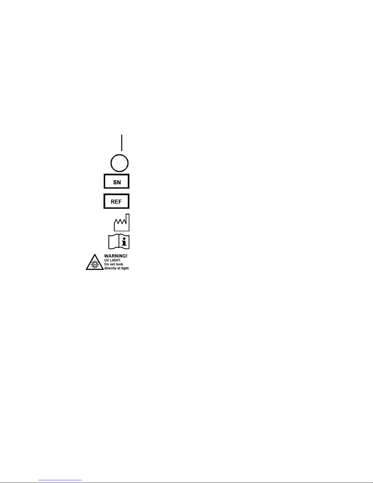
Safety symbols and markings
4 Varioskan™ User Manual Thermo Electron Corporation
These symbols are intended to draw your attention to particularly
important information and alert you to the presence of hazards as
indicated.
The following symbols and markings appear on the type label and the
instrument itself.
Power ON ▲
Power OFF ▲
Serial number ▲
Catalog number ▲
Date of manufacture ▲
Consult instructions for use ▲
Risk of radiation injury ▲
A black label with the following text (Figure 2–3):
CAUTION: WARNING: DISCONNECT SUPPLY BEFORE
SERVICING and AVERTISSEMENT: COUPER
L'ALIMENTATION AVANT L'ENTRETIEN ET LE
DEPANNAGE. ▲
Safety symbols
and markings
Safety symbols and
markings used on
the Varioskan
Page 7
About This User Manual
Safety symbols and markings
Thermo Electron Corporation Varioskan™ User Manual 5
The following symbols and markings appear in this User Manual.
Warning Risk of electric shock. ▲
Warning Biohazard risk. ▲
Warning Hot surface, risk of burns. ▲
Warning Risk of injury to the user(s). ▲
Warning Risk of ultraviolet radiation injury. ▲
Caution Risk of damage to the instrument, other equipment or loss of
performance or function in a specific application. ▲
Note Marks a hint, important information that is useful in the
optimum operation of the system, or an item of interest. ▲
W
arning and other
markings used in
the documentation
Page 8

About This User Manual
Instrument safety and guidelines for use
6 Varioskan™ User Manual Thermo Electron Corporation
1. Always follow basic safety precautions when using the Varioskan to
reduce the risk of injury, biohazardous contamination, fire, or
electrical shock.
2. Read this User Manual in its entirety prior to operating the
instrument. Failure to read, understand, and follow the instructions
in the manual may result in damage to the instrument, injury to
laboratory and operating personnel or poor instrument
performance.
3. Observe all “Warning”, “Caution”, and “Note” statements as well as
safety symbols and markings on the instrument and in the
documentation.
4. Never open any other covers of the Varioskan than the dispenser
sliding cover (Figure 2–2) or measurement chamber door
(Figure 2–2) while the instrument is plugged into a power source.
5. Never open the measurement chamber door while the instrument is
busy (when the LED indicator is orange).
6. You can push in the tray manually only when the instrument is
switched off.
7. Never force a microplate into the instrument.
8. The Varioskan is intended for laboratory research use only. Observe
proper laboratory safety precautions, such as wearing protective
clothing and following approved laboratory safety procedures.
9. Preventative maintenance instructions should be followed closely to
keep the instrument in the best condition for maximum reliability.
A poorly maintained instrument will not give the best results.
Instrument safety
and guidelines
for use
Page 9

Thermo Electron Corporation Varioskan™ User Manual 7
Contents
Who uses this user manual ................................................................3
How to use this user manual ............................................................. 3
For more information .......................................................................3
Safety symbols and markings.............................................................4
Safety symbols and markings used on the Varioskan ......................4
Warning and other markings used in the documentation ...............5
Instrument safety and guidelines for use............................................ 6
Introduction to the Varioskan.................................................................... 15
Introduction.................................................................................... 15
Intended use.................................................................................... 15
Advantages of using Varioskan ........................................................ 16
Functional Description ............................................................................... 17
Instrument layout............................................................................17
Front view....................................................................................17
Back view..................................................................................... 17
Internal view ................................................................................ 18
Measurement techniques................................................................. 19
Fluorescence intensity ..................................................................19
Time-resolved fluorescence........................................................... 19
Photometry .................................................................................. 20
Optical system................................................................................. 21
Principle of the optical system...................................................... 21
Excitation optics........................................................................ 22
Measurement optics .................................................................. 23
Emission reading module .......................................................... 24
Photometric measurement module............................................ 24
Dispenser option............................................................................. 25
Incubator ........................................................................................27
Control switches .............................................................................27
Track mechanism............................................................................ 28
Tray options.................................................................................... 29
Tray composition......................................................................... 30
Universal tray with adapters .........................................................31
Robotic tray ................................................................................. 33
How to change the location of the holder for the tip priming
vessel ......................................................................................... 34
How to remove or replace the robotic tray adapter.................... 35
Installation .................................................................................................... 37
Installation checklist........................................................................37
What to do upon delivery ...............................................................38
Chapter 1
Chapter 2
Chapter 3
Page 10

Contents
8 Varioskan™ User Manual Thermo Electron Corporation
How to unpack ............................................................................ 38
Checking delivery for completeness.............................................. 38
Checking for damage during transport ......................................... 38
Environmental requirements ........................................................39
Things to avoid ............................................................................39
Technical prerequisites................................................................. 39
Setups before you put the instrument into operation....................... 40
How to release the transport lock ................................................. 40
How to install the tray ................................................................. 43
How to setup the optional dispenser ............................................45
Installation of SkanIt Software .....................................................47
How to ensure startup.................................................................. 47
Operational check ........................................................................... 48
Automatic runtime calibration ..................................................... 49
Routine Operation ........................................................................................51
Do’s and Don’ts of the Varioskan ...................................................51
Do ...............................................................................................51
Don’t ........................................................................................... 52
Switching on ...................................................................................53
Loading the microplate ................................................................54
Fluorometric measurement..............................................................55
Fluorometric spectrum scanning .....................................................57
Photometric measurement............................................................... 58
Photometric spectrum scanning ......................................................58
Other functions............................................................................... 59
Orbital shaking ............................................................................59
Incubating.................................................................................... 60
Dispensing ................................................................................... 61
Priming..................................................................................... 61
Tip priming ..............................................................................62
Dispenser washing..................................................................... 62
Dispensing and measurement....................................................62
Helpful hints.............................................................................63
Chemical resistance of the dispenser..........................................63
Shutdown .......................................................................................66
Emergency situations ......................................................................67
Maintenance .................................................................................................69
Maintenance checklist ..................................................................... 69
Regular and preventive maintenance ............................................... 70
How to clean the measurement chamber......................................71
How to clean the tray................................................................... 72
How to clean the reagent basin and dispensing area .....................73
Routine maintenance of the optional dispenser ............................ 73
Daily maintenance .......................................................................73
Weekly maintenance .................................................................... 74
Weak detergent or 10% bleach.................................................. 74
Weak base and acid in sequence ................................................... 74
Chapter 4
Chapter 5
Page 11

Contents
Thermo Electron Corporation Varioskan™ User Manual 9
Periodic maintenance ......................................................................75
Replacing the aspirate tube assembly or the complete dispensing
tube assembly............................................................................... 75
Replacing a dispensing tip ............................................................ 76
Replacing a dispenser syringe .......................................................77
Replacing the 3-port valve............................................................... 78
Disposal of materials ....................................................................... 79
Decontamination procedure............................................................ 79
How to refit the transport lock.....................................................81
Maintaining a system log................................................................. 83
How to pack for service...................................................................83
Service contracts..............................................................................84
Disposal of the instrument .............................................................. 84
Technical Specifications ........................................................................... 85
General specifications......................................................................85
Performance specifications ..............................................................86
Safety specifications...................................................................... 88
In conformity with the requirements...............................................89
Frequently Asked Questions...................................................................... 91
Troubleshooting Guide ............................................................................... 95
Error and warning codes .................................................................95
Service request protocol................................................................... 99
Certificate of Decontamination....................................................... 99
Ordering Information................................................................................. 101
List of spare parts and accessories ..................................................101
Upgrade kits.................................................................................. 102
References .................................................................................................. 103
Useful web links............................................................................ 103
Literature ......................................................................................105
Fluorescence intensity ................................................................105
Time-resolved fluorescence......................................................... 105
Photometry ................................................................................ 106
System Log .................................................................................................. 107
Varioskan Brief User’s Guide.................................................................. 109
Certificate of Decontamination............................................................... 111
Varioskan Feedback Form........................................................................ 113
Chapter 6
Chapter 7
Chapter 8
Chapter 9
Chapter 10
Appendix A
Appendix B
Appendix C
Appendix D
Page 12

Contents
10 Varioskan™ User Manual Thermo Electron Corporation
Glossary........................................................................................................115
Index .............................................................................................................117
Notes.............................................................................................................121
Page 13

Figures
Thermo Electron Corporation Varioskan™ User Manual 11
Figures
Figure 1–1. Varioskan spectral scanning multimode reader ........................ 15
Figure 2–2. Varioskan front view .................................................................. 17
Figure 2–3. Varioskan back view................................................................... 17
Figure 2–4. Close-up of the computer and mains supply connectors .......... 18
Figure 2–5. Varioskan internal view.............................................................. 18
Figure 2–6. Varioskan optics ......................................................................... 21
Figure 2–7. Excitation optics ......................................................................... 22
Figure 2–8. Principle of the double monochromator..................................... 23
Figure 2–9. Measurement optics .................................................................. 23
Figure 2–10. Emission optics......................................................................... 24
Figure 2–11. Photometric measurement module.......................................... 25
Figure 2–12. Varioskan dispensing system................................................... 26
Figure 2–13. Dispensing tip options: 0.40 mm, and 0.25 mm ...................... 26
Figure 2–14. Varioskan incubator cross-section........................................... 27
Figure 2–15. Control switches....................................................................... 28
Figure 2–16. Part of the Varioskan track mechanism ................................... 29
Figure 2–17. Assembly picture of the universal tray .................................... 30
Figure 2–18. Robotic tray fitted with adapter for plate w/o lid, #126 ......... 33
Figure 2–19. Changing the location of the tip priming vessel holder .......... 34
Figure 2–20. Removing or replacing the adapter for plate w/o lid, #126 .... 35
Figure 3–21. Transport lock and transport lock tag present......................... 40
Figure 3–22. Dispenser sliding cover and measurement chamber door
opened ............................................................................................................. 41
Figure 3–23. Front cover removed................................................................. 41
Figure 3–24.
Transport lock fastened (screws 1 – 4 shown)........................ 42
Figure 3–25. Releasing the transport lock (screws 1 – 4 shown)................. 42
Figure 3–26. Transport lock in its horizontal storage position (screws 3 and
4 shown) .......................................................................................................... 43
Figure 3–27. Tray holder................................................................................ 44
Figure 3–28. Fastening the tray frame to the tray holder............................. 45
Figure 3–29. Close-up of the positioning lever when the tray is out ........... 45
Figure 3–30. Varioskan with the dispenser sliding cover open.................... 46
Figure 3–31. Protective cap removed from the dispensing tip 5 – 1000 µl
(0.40 mm) ......................................................................................................... 47
Figure 3–32. Dispenser assembly ................................................................. 47
Figure 3–33. Connecting the mains supply cable ......................................... 48
Figure 4–34. Microplate loaded .................................................................... 54
Figure 4–35. Dynamic range selection.......................................................... 55
Figure 4–36. Structure of the TRF measurement cycle................................. 57
Page 14

Figures
12 Varioskan™ User Manual Thermo Electron Corporation
Figure 4–37. ON-OFF period time and total shaking time............................. 59
Figure 4–38. Speed & diameter combinations for different plate formats ..60
Figure 5–39. Front cover removed .................................................................71
Figure 5–40. Internal view of the measurement chamber ............................ 72
Figure 5–41. Replacing the dispensing tip (A)............................................... 76
Figure 5–42. Replacing the dispensing tip (B)............................................... 76
Figure 5–43. Dispenser assembly..................................................................77
Figure 5–44. Replacing the dispenser syringe ..............................................78
Figure 5–45. 3-port valve replacement..........................................................79
Figure 5–46. Transport lock released (A) and fastened (B) (screws 1 – 4
shown)..............................................................................................................82
Page 15

Tables
Thermo Electron Corporation Varioskan™ User Manual 13
Tables
Table 2–1. Compatibility of the universal tray and plate-specific adapters 32
Table 2–2. Compatibility of the robotic tray and plate-specific adapter...... 33
Table 3–3. Installation checklist.................................................................... 37
Table 4–4. LED indicator................................................................................ 53
Table 4–5. Compatibility chart of solvents suitable with the plastic
materials used in the dispenser...................................................................... 64
Table 5–6. Maintenance checklist ................................................................ 69
Table 5–7. Example of a system log.............................................................. 83
Table 6–8. Technical specifications .............................................................. 85
Table 6–9. Fluorometry .................................................................................. 86
Table 6–10. Photometry................................................................................. 87
Table 6–11. Incubator .................................................................................... 87
Table 6–12. Shaker ........................................................................................ 88
Table 6–13. Dispenser ................................................................................... 88
Table 7–14. Tray vs. plate-specific adapter .................................................. 92
Table 8–15. Error codes reported .................................................................. 95
Table 8–16. Warning codes reported............................................................ 98
Table 9–17. Instrument catalog numbers.................................................... 101
Table 9–18. Codes for spare parts and accessories ................................... 101
Table 9–19. Codes for upgrade kits............................................................. 102
Page 16

Tables
14 Varioskan™ User Manual Thermo Electron Corporation
Page 17
Thermo Electron Corporation Varioskan™ User Manual 15
Chapter 1
Introduction to the Varioskan
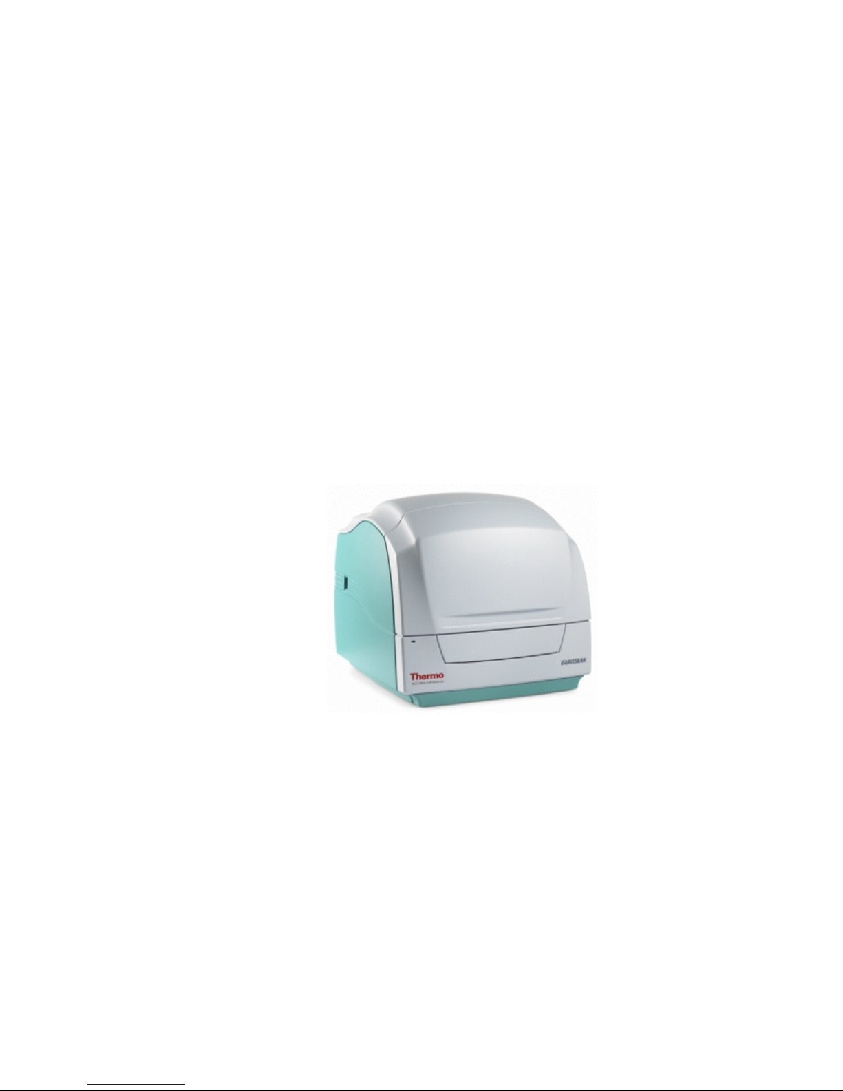
The Thermo Electron Varioskan (Figure 1–1) is an advanced spectral
scanning multimode reader. The Varioskan is used to measure
fluorescence intensity, time-resolved fluorescence (TRF) and absorbance
in end point, kinetic and spectral measurements in the UV/Vis range
from appropriate microplate formats. In fluorometric measurements
appropriate 6- to 1536-well plates can be used, and correspondingly
appropriate 6- to 384-well plates in photometric measurements.
Incubation can be carried out in a controlled incubation temperature.
The instrument also allows shaking and reagent dispensing. The
instrument is run on SkanIt Software 2.2 (or greater), which controls all
the instrument functions and provides data processing as well as
reporting functions.
Figure 1–1. Varioskan spectral scanning multimode reader
The Varioskan spectral scanning multimode reader is intended for
professional laboratory research use by trained personnel, who
understand the nature of fluorometry and photometry. The Varioskan
is used to measure fluorescence intensity and time-resolved fluorescence
(TRF) from appropriate 6- to 1536-well plate formats or absorbance
from appropriate 6- to 384-well plate formats mentioned in the
manual. It also has incubation, shaking and reagent dispensing
capabilities.
Use for self-testing is excluded.
For validation of the entire system, it is recommended that Good
Laboratory Practices (GLP) are followed to guarantee reliable analyses.
Refer to Chapter 6: “Technical Specifications”.
Introduction
Intended use
Page 18

Introduction to the Varioskan
Advantages of using Varioskan
16 Varioskan™ User Manual Thermo Electron Corporation
The Varioskan provides several advantages relating mainly to the
principle of operation in that it:
● Supports applications requiring measurement in the UV/Vis/NIR
wavelength range
● Allows optimization of the measurement wavelengths according to
the application needs
● Allows use of freely selectable wavelengths and spectral scanning
● Enables measurement of multiple labels from the same well
● Allows optimization of the assays to different plate formats
depending on the throughput requirements
● Enables precise incubation of temperature-critical assays due to the
unique design of the universal tray
● Enables fast kinetic measurements due to simultaneous
measurement and dispensing
● Enables automation due to robot compatibility
● Is controlled by SkanIt Software that provides features required to
make comprehensive calculations and reports
● Ensures high-quality performance due to automatic runtime
calibration and operational checks, including safety features
Advantages of
using Varioskan
Page 19

Thermo Electron Corporation Varioskan™ User Manual 17
Chapter 2
Functional Description
This section shows the front, internal and back views of the Varioskan
instrument.
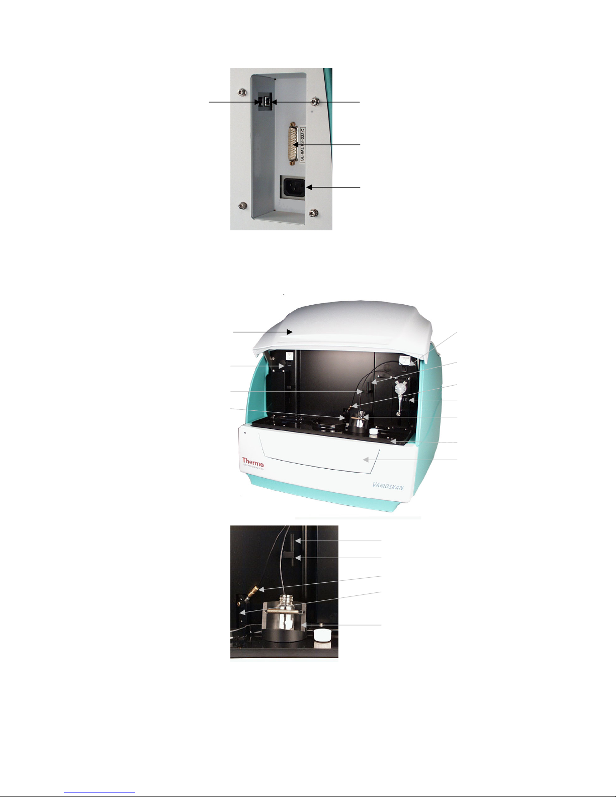
Figure 2–2. Varioskan front view
Figure 2–3. Varioskan back view
Instrument
layout
Front view
Back view
ON/OFF switch
Power, busy and
Dispenser sliding cover
Measurement chamber door
Front cover
Cooling-fan outlet
Serial connector
Warning marking
USB connector
ON/OFF switch
Mains power supply connector
Type label
Indentation for lifting Varioskan
Indentation for lifting Varioskan
Page 20
Functional Description
Instrument layout
18 Varioskan™ User Manual Thermo Electron Corporation
Figure 2–4. Close-up of the computer and mains supply connectors
Figure 2–5. Varioskan internal view
Internal view
Dispensing head positioner (dispensing
head in positioner while dispensing; blind
plug present when no dispensing)
USB connector
Ethernet connector (not in use)
Serial connector
Mains power supply connector
Dispenser sliding cover
Plate In/Out switch
Dispensing head holder
Dispensing head positioner
(dispensing head in positioner
while dispensing; blind plug
present when no dispensing)
Prime/Empty switch
(opt., with dispenser)
Dispensing head (opt.)
Dispenser (opt.)
Reagent bottle holder
Reagent basin
Measurement
chamber door
Blind plug
Dispensing head holder
Reagent bottle holder
Dispensing head (opt.)
Blind plug
Page 21

Functional Description
Measurement techniques
Thermo Electron Corporation Varioskan™ User Manual 19
This section describes the relevant measurement techniques, including
fluorescence intensity, time-resolved fluorescence and photometry.
Fluorescence is the phenomenon in which absorption of excitation light
of a given wavelength by a fluorescent molecule is followed by the
emission of light at longer wavelengths. Fluorescence intensity of the
emitted light (RFU) at selected excitation and emission wavelengths is
proportional to the concentration of the fluorescent molecule being
investigated.
Fluorescent molecules have two characteristic spectra: an excitation
spectrum which shows the wavelength-dependent amount of light
absorbed and an emission spectrum which shows the wavelengthdependent amount of light emitted. No two compounds have exactly
the same fluorescence spectra, thus, making fluorometry a highly
specific analytical technique.
One of the major advantages of fluorescence detection is high
sensitivity. This is important as relatively small changes in, for example,
ion concentration in living cells can have significant physiological
effects. In addition of fluorescence being a versatile tool in cell biology,
biochemistry and molecular biology, it is also a powerful technique for
studying molecular interactions in analytical chemistry, physiology,
photochemistry, and environmental science.
Fluorescence resonance energy transfer (FRET) is a fluorescence
intensity based measurement technique. Two labels are required for
FRET measurements: donor (fluorescent), and acceptor (either
fluorescent or non-fluorescent). The emission spectrum of the donor
needs to overlap with the absorption spectrum of the acceptor to allow
the energy transfer to happen.
FRET allows homogeneous assay formats to be used in the detection of
biological interactions. The change in the intensity of the generated
FRET signal can be related to specific biological events, such as
enzyme-mediated cleavage of DNA or protein substrates, protein-DNA
interactions and protein-peptide interactions.
Time-resolved fluorescence (TRF) is a special form of fluorescence
intensity where fluorescence lifetime of the signal is remarkably longer
than in fluorescence intensity. TRF uses lanthanide labels which have
similar excitation and emission spectra as fluorescence intensity labels.
Every TRF label has a unique fluorescence lifetime parameter τ (tau)
which reflects the duration of fluorescence emission after excitation has
been switched off. In TRF measurements the lanthanide label is excited
with a light flash and the resulting emission is detected after a labelspecific delay time.
Typical biological samples have a fluorescence background with a very
short lifetime, which has an effect on fluorescence intensity
Measurement
techniques
Fluorescence
intensity
Time-resolved
fluorescence
Page 22

Functional Description
Measurement techniques
20 Varioskan™ User Manual Thermo Electron Corporation
measurements. In TRF technology this biological background has
decayed before the TRF signal is measured, giving improved assay
performance.
Time-resolved fluorescence labels can well be used for resonance energy
transfer applications as fluorescence intensity labels. This time-resolved
fluorescence energy transfer technology is known as TR-FRET.
When a beam of light enters a sample, part of the light is absorbed by
the sample and the rest is transmitted (passes through the sample).
Absorbance (A) is defined by Equation 1:
A = log (Io/I) Equation 1
where: Io = intensity of incident light
I = intensity of transmitted light
The absorbance is linearly related to the concentration of the absorbing
compound by Bouguer-Lambert-Beer’s Law (Equation 2).
A = εC d Equation 2
where: A = absorbance
ε = molar absorption coefficient [l/(mol*cm)]
C = concentration [mol/l]
d = pathlength [cm].
Photometry
Page 23
Functional Description
Optical system
Thermo Electron Corporation Varioskan™ User Manual 21
The Varioskan employs fluorometric and photometric measurement
techniques. Fluorometric measurements are made from the top of the
well and photometric measurements are made through the well.
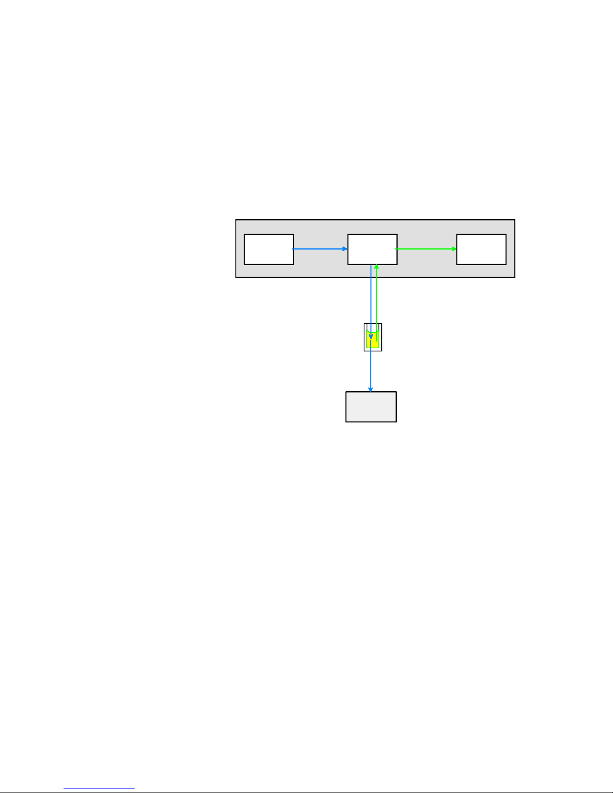
The principle of the Varioskan optical measurement modules is shown
in the following block diagram (Figure 2–6). Each submodule is
described separately in the subsequent lower-level block diagrams
(Figure 2–7 through Figure 2–11).
Figure 2–6. Varioskan optics
The Varioskan optical unit consists of four subunits (Figure 2–6):
● The excitation optics produces light of selected wavelength for
fluorometric measurement and also for photometric measurement.
Refer to “Excitation optics” on page 22.
● The measurement optics produces a high-definition optical beam
for fluorometric and photometric measurements. The excitation
light reference detector is incorporated into the measurement
optics. Refer to “Measurement optics” on page 23.
● The emission optics carries out the reading of a selected wavelength
for fluorometry. Refer to “Emission reading module” on page 24.
● The photometric measurement module measures light-beam
intensity passing through the well. Refer to “Photometric
measurement module” on page 24.
Optical system
Principle of the
optical system
Excitation
optics
Emission
optics
Measurement
optics
Excitation / emission optical module
Photometric
measurement
module
Fluorescence
excitation
Fluorescence
emission
Photometric
beam through
the plate
Page 24
Functional Description
Optical system
22 Varioskan™ User Manual Thermo Electron Corporation
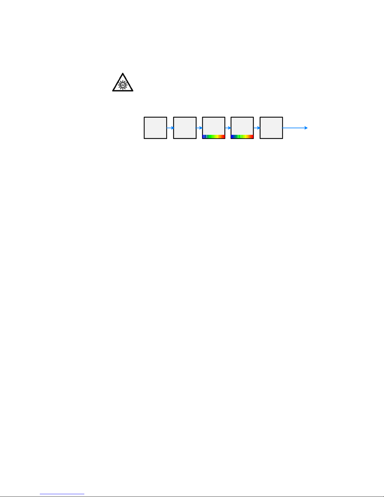
The excitation optics (Figure 2–7) consists of the light source and the
wavelength selection devices.
Warning Do not open the optical covers under any circumstances.
There is a risk of ultraviolet radiation injury.
Only authorized service personnel has permission to open the optical
covers. ▲
Xenon
flash
module
Diffraction
order
selection
filters
1. Monochromat or
2. Monochromator
Bandwidth
selector
Excitation light
Figure 2–7. Excitation optics
Light source:
A xenon flash lamp is used as the light source. The lamp provides a
wide spectral range needed for photometry and fluorometry. The lamp
is pulsed at a 100 Hz rate and activated only when measuring. A short
light pulse enables accurate TRF measurements.
One measurement consists of 1 to 1000 flash pulses according to the
measurement quality and measurement speed requirements.
Diffraction order selection filters:
Excitation diffraction order filters, i.e., cut-off filters, are used to block
unwanted harmonic transmission of monochromators. The correct
diffraction order filter is selected automatically.
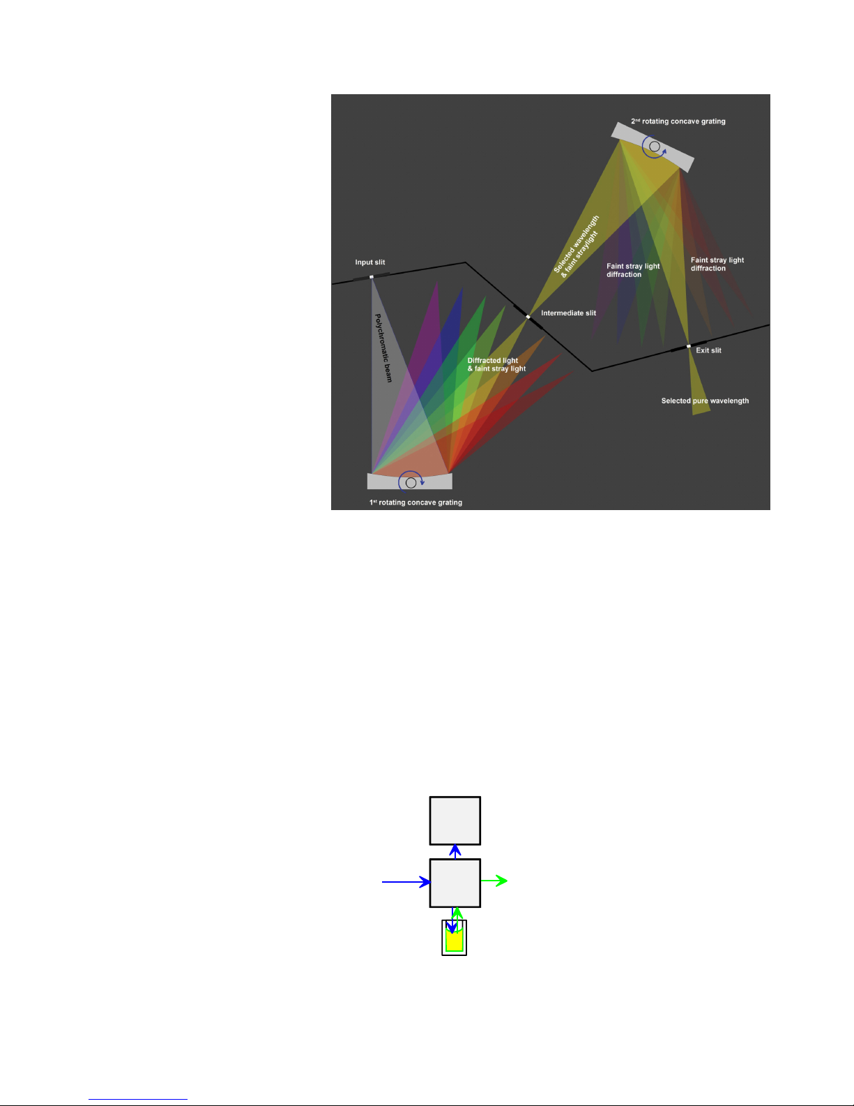
Monochromators:
The monochromator is based on the diffraction grating. A grooved
surface of the grating diffracts the different colors into different angles
and a bandpass wavelength is selected by rotating the grating
(Figure 2–8). The final pickup of the desired wavelength band is made
by an entrance/exit slit combination.
Two monochromators are serially connected for high spectral quality
and this essentially minimizes leakage of undesired wavelengths, i.e.,
stray light.
Excitation optics
Page 25
Functional Description
Optical system
Thermo Electron Corporation Varioskan™ User Manual 23
Figure 2–8. Principle of the double monochromator
Bandwidth selector:
The bandwidth is set by means of the monochromator slit width. A
selection of two bandwidths, 5 nm and 12 nm, is made by controlling
the slits.
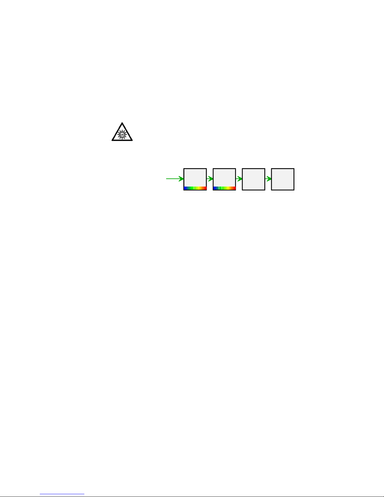
The measurement optics module (Figure 2–9) is the front surface
mirror optics system to generate a wavelength-independent, highdefinition beam for fluorometric measurement and for photometric
measurement. Simultaneously the measurement optics collects emission
light, which is fed to the emission reading channel.
Figure 2–9. Measurement optics
Measurement optics
Measurement
optics
Reference
sensor
Excitati on light
Emission light
Page 26
Functional Description
Optical system
24 Varioskan™ User Manual Thermo Electron Corporation
The excitation beam intensity is measured by the reference sensor
before the measurement beam enters the well. The reference sensor
value is used to correct the result level to compensate for long-term and
short-term flash intensity fluctuations.
The emission optics (Figure 2–10) is basically similar to the excitation
optics. Refer to “Excitation optics” on page 22.
Warning Do not open the optical covers under any circumstances.
There is a risk of ultraviolet radiation injury.
Only authorized service personnel has permission to open the optical
covers. ▲
Figure 2–10. Emission optics
Emission monochromators:
Two diffraction grating monochromators are connected serially as in
the excitation optics to gain high stray-light rejection. The
monochromator bandwidth is 12 nm.
Emission diffraction order filters:
Emission diffraction order filters are used to block unwanted harmonic
transmission from the monochromators.
Emission detector:
Emission light is converted into electrical signals by the photomultiplier
tube (PMT). The dynamic range is adjusted automatically (AutoRange
default) or manually according to the measurement situations. The
manual dynamic range setting has three selections: Low; Medium, and
High range (Figure 4–35).
Photometric measurement is carried out by using the excitation optics
module as the photometric measurement light source.
The photometric measurement module (Figure 2–11) is just
underneath the fluorometric measurement position.
Emission reading module
Photometric
measurement module
Diffractio n
order
selecti on
filters
3. Monochromator
4. Monochromat or
Photomultiplier
tube
(PMT)
Emission light
from the well
Page 27
Functional Description
Dispenser option
Thermo Electron Corporation Varioskan™ User Manual 25
Measurement
optics
Reference
sensor
Excitat ion light
Photometer
module
Figure 2–11. Photometric measurement module
The optional dispenser (Figure 2–5) is located in the instrument
housing (Figure 2–2) under the dispenser sliding cover (Figure 2–5).
The dispenser is intended for accurate dispensing, in the range of 1 to
1000 µl with increments of 1 µl. The dispenser consists of a pump with
a valve, a syringe (1.0 ml), tubing and a dispensing head (Figure 2–12).
The instrument supports simultaneous dispensing and reading,
enabling fast signal monitoring from the very start of the reaction. The
dispenser is located close to the measurement position in order to
achieve a low dead volume and minimal reagent consumption. This is
important when using expensive reagents. Optimal design of the
reagent bottle holder (Figure 2–5) also aids utilization of all the reagent.
The combination of a special dispensing tip (Figure 2–12) and the tip
priming feature ensures that even very small volumes can be dispensed
accurately.
Dispenser option
Page 28
Functional Description
Dispenser option
26 Varioskan™ User Manual Thermo Electron Corporation
Figure 2–12. Varioskan dispensing system
There are two different dispensing tip options: the black dispensing tip
0.40 (∅ 0.40 mm), and the transparent dispensing tip 0.25 (∅
0.25 mm) (Fig. 4.12). Dispensing tip 0.25 (Cat. no. N03081) is
intended for small volumes in the range of 1 to 20 µl. Dispensing tip
0.40 (Cat. no. N03080) is recommended for volumes > 5 µl, since the
dispensing is then more rapid.
Figure 2–13. Dispensing tip options: 0.40 mm, and 0.25 mm
Refer to “How to setup the optional dispenser” on page 45.
Complete dispensing tube
assembly, i.e., output tubing
3-port valve
Dispenser syringe (1.0 ml) and plunger
Aspirate tube assembly,
i.e., input tubing (incl.
tubing and end weight)
Dispensing tip (2 options:
0.40 mm, and 0.25 mm)
Plunger lock screw
Page 29
Functional Description
Incubator
Thermo Electron Corporation Varioskan™ User Manual 27
The accurate incubator is useful for temperature-critical applications,
for example, certain enzyme assays and cell-based applications.
The universal tray is specially designed for precise and uniform
temperature control. The incubator consists of two main parts: a fixed
upper heater (Figure 2–14), and a moving universal tray (Figure 2–14).
The microplate (Figure 2–14) is surrounded by temperature-controlled
heaters with the exception of a narrow space between the upper heater
and the universal tray and the reading windows (Figure 2–14). The tray
and the upper heater together form the isothermal chamber.
Note that incubation can be carried out with the Varioskan universal
tray and a correct adapter. Refer to “Universal tray with adapters” on
page 31. The upper element is slightly warmer than the lower element
to avoid condensation on the plate lid.
On the other hand, heating can be carried out with all trays and
adapters, e.g., the robotic tray, by using only the upper heater element
located in the ceiling of the measurement chamber to minimize
condensation in the plate lid.
Figure 2–14. Varioskan incubator cross-section
There are two rocker switches in all: one Plate In/Out rocker switch for
driving the plate carrier in or out (Plate In/Out function)
(Figure 2–15), and one Prime/Empty rocker switch for priming and
emptying the dispenser tubing (Prime/Empty function) (Figure 2–15).
Note that the Prime/Empty switch is only present if there is a dispenser
fitted. The Prime function requires a microplate to be loaded and this is
automatically checked before priming. The Empty function does not
require a microplate to be present. The Prime/Empty switch has an
additional function as a washing option of the dispenser. Refer to
“Dispenser washing” on page 62.
Incubator
Control switches
Upper heater (slightly tilted)
Universal tray frame
96-well adapter for
plate without lid, #2
Microplate
Bottom reading hole
Top reading window
Page 30
Functional Description
Track mechanism
28 Varioskan™ User Manual Thermo Electron Corporation
Figure 2–15. Control switches
The track mechanism (Figure 2–16) has been specifically designed to
obtain excellent measurement results for different plate formats. The
position calibration hole on the top left corner of the tray is read at
startup, and plate positioning is adjusted accordingly. Also, if the tray is
changed, the calibration hole is read again.
The home sensors of the X and Y carriages are used for checking the
correctness of the plate position. The check is done each time the
carriage passes the home position, and also always when the plate is
driven out.
Note that movement of the track mechanism can perform orbital
shaking. Refer to “Orbital shaking” on page 59 and Table 6–12.
Track
mechanism
PLATE IN/OUT control switch
DISPENSER PRIME/EMPTY
control switch
Page 31

Functional Description
Tray options
Thermo Electron Corporation Varioskan™ User Manual 29
Figure 2–16. Part of the Varioskan track mechanism
Two different kinds of trays can be used with the Varioskan: (1) the
universal tray, and (2) the robotic tray. Refer to Table 2–1 and
Table 2–2.
The universal tray (Figure 2–17) can be used with or without
incubation. It is suitable for the most common 6- to 1536-well plate
formats. Fluorescence intensity and TRF measurements can be carried
out with 6- to 1536-well plates, and photometric measurements with
6- to 384-well plates. You can use a microplate with or without a lid
(cover) depending on the adapters used. The adapters are detachable
with two thicknesses depending on whether it is intended for
microplates with or without lids. If you want to dispense, use an
adapter intended for use with microplates without lids. Refer to
“Universal tray with adapters” on page 31.
The robotic tray (Figure 2–18) is intended for use with robots with
96- to 1536-well plate formats. You can use a microplate with or
without a lid. The robotic tray supports the robotic configuration of
either portrait or landscape orientation. Dispensing is possible with the
elevation adapter intended for 96- and 384-well plates without lids.
Remove the adapter when you use microplates with lids. Refer to
“Robotic tray” on page 33.
The tray is inserted into the tray holder. Refer to “How to install the
tray” on page 43. The A1 well position is marked on the tray frames to
facilitate easy and correct insertion of the microplate.
Tray options
Y
X
Y-carriage
X-carriage
Reference chip
Tray holder
Tray
Page 32

Functional Description
Tray options
30 Varioskan™ User Manual Thermo Electron Corporation
The tray composition is shown in Figure 2–17 and described below.
Figure 2–17. Assembly picture of the universal tray
The tray is fastened to the tray holder, which is part of the track
mechanism, by a screw fix (Figure 2–17). Refer to “How to install the
tray” on page 43.
The universal frame (Figure 2–17) is the basic part of the universal tray,
into which adapters are fitted.
The adapter (Figure 2–17) is the detachable part that is fitted into the
universal frame. There are adapters for microplates with or without lids.
Some adapters support incubation, others do not (Table 2–1 and
Table 2–2).
For automatic identification of tray/adapter combinations, there are
codes that refer to the coding system employed (Figure 2–17). The
adapters are also marked with a visual identification number and the
text WITH LID or NO LID to help differentiate them from one
another.
The positioning lever (Figure 2–17) is used for automatic positioning of
the microplate.
It is recommended to use the tip priming feature for accurate
dispensing, particularly when the dispensing volumes are small, for
example, 1 to 20 µl. For more information on the tip priming feature,
refer to “Dispensing” on page 61. All trays have a cavity for the tip
priming vessel. The holder for the tip priming vessel is located on the
left side of the universal frame (Figure 2–17). The robotic tray has two
optional locations for the tip priming vessel, depending on the robotic
Tray composition
Screw fix
Frame
Adapter
Means of identification of
tray/adapter combinations
Positioning lever
Holder for tip priming vessel
Means of identification of
tray/adapter combinations
Tip priming vessel
Screw fix
Position calibration hole(s)
Holder for tip priming vessel
384-well adapter for
plate without lid, #4
Positioning lever
Universal frame
Page 33

Functional Description
Tray options
Thermo Electron Corporation Varioskan™ User Manual 31
configuration of either portrait (position A) or landscape orientation
(position B) (Figure 2–19).
The tip priming vessel (Figure 2–17) is an 8-well plate strip (1 x 8
Thermo Microtiter Solid Strip Assembly).
There are three holes for the automatic calibration and alignment of the
track mechanism. The hole marked (Figure 2–17) is used for the
positional check of the track mechanism at startup and when changing
the tray.
This section provides information on the more commonly used
universal tray and the adapters one can use with it.
Incubation can be carried out with 96- to 1536-well plates using the
universal tray and a correct adapter. You need different adapters for
plates with or without lids.
The universal tray with a 6- to 48-well plate adapter supports
measurement but not incubation. An adapter that supports incubation
for 24- to 48-well plate formats can be ordered on request.
Note The efficiency of incubation may be remarkably reduced with
large well-diameter plates. ▲
Caution Do not use plates with dimensions exceeding the top rim of
the tray. Note that the maximum total height of plates is manufacturer
related. ▲
Refer to Table 2–1 and Chapter 9: “Ordering Information”. For more
information on plate type settings, refer to SkanIt Software for Varioskan
User Manual (Cat. no. N02723).
Tip priming vessel
Position calibration hole(s)
Universal tray with
adapters
Universal tray:
Universal frame
– adapter for incubating and
measuring 96- and 384-well plates or
– adapter for measuring 6- to 48-well
plates
Page 34

Functional Description
Tray options
32 Varioskan™ User Manual Thermo Electron Corporation
Table 2–1. Compatibility of the universal tray and plate-specific adapters
Picture ID no. Description Measurement Incubation Dispensing
#2 96-well adapter for plate without lid*)
To be used with the most common 96-well
plate formats without lids. Incubation and
dispensing are possible.
yes yes yes
#3 96-well adapter for plate with lid
To be used with the most common 96-well
plate formats with lids. Incubation is possible.
No dispensing.
yes yes no
#4 384-well adapter for plate without lid*)
To be used with the most common 384-well
plate formats without lids. Incubation and
dispensing are possible with 384-well plates.
Recommended for 1536-well plate reading.
yes yes yes 384
no 1536
#5 384-well adapter for plate with lid
To be used with the most common 384-well
plate formats with lids. Incubation is possible.
No dispensing.
yes yes no
#80 6 – 48-well adapter for plate without lid*
)
To be used with the most common 6- to 48well plate formats without lids. Incubation is
not supported. Dispensing is possible.
yes no yes
#48 6 – 48-well adapter for plate with lid
To be used with the most common 6- to 48well plate formats with lids. Incubation and
dispensing are not supported.
yes no no
*)
included in standard deliveries
Page 35

Functional Description
Tray options
Thermo Electron Corporation Varioskan™ User Manual 33
Table 2–2. Compatibility of the robotic tray and plate-specific adapter
Picture ID no. Description Measurement Incubation Dispensing
#126 Robotic tray with adapter for plate
without lid
To be used with the most common 96- to
1536-well plate formats without lids.
Incubation is not supported. Dispensing is
possible with 96- and 384-well plates.
yes no yes 96 & 384
no 1536
#127 Robotic tray without adapter for
plate with lid
To be used with the most common 96- to
1536-well plate formats with lids.
Incubation and dispensing are not
supported.
yes no no
The robotic tray comes equipped with the elevation adapter for plate
without lid, #126 and is thus directly ready for measurement of 96- to
1536-well plates and dispensing of 96- and 384-well plates
(Figure 2–18).
Figure 2–18. Robotic tray fitted with adapter for plate w/o lid, #126
Remove the adapter when you use microplates with lids. Refer to “How
to remove or replace the robotic tray adapter” on page 35.
There are fixed side supports on both the robotic tray and the adapter.
When the tray comes out, the side supports prevent the plate from
moving.
It is recommended to use the tip priming feature for accurate
dispensing, particularly when the dispensing volumes are small, for
Robotic tray
Robotic tray:
– adapter for measuring and
dispensing plates without lids or
– no adapter when measuring
plates with lids
Tip priming vessel in
holder (position A,
portrait orientation)
Positioning
lever
Robotic tray
frame
Page 36

Functional Description
Tray options
34 Varioskan™ User Manual Thermo Electron Corporation
example, 1 to 20 µl. For more information on the tip priming feature,
refer to “Dispensing” on page 61. The tip priming vessel is an 8-well
plate strip (1 x 8 Thermo Microtiter Solid Strip Assembly).
Refer to Table 2–2 and Chapter 9: “Ordering Information”.
The robotic tray frame designed for robot compatibility has a cavity for
the tip priming vessel located in either of two optional locations: on the
left side (= position A) (Figure 2–19), or in the front (= position B)
(Figure 2–19) of the robotic tray frame. This is due to the space
requirements of the optional portrait and landscape orientations of the
robotic arms. If the robotic access is portrait, the tip priming vessel
must be located on the left side of the microplate. However, if the
robotic arm accesses the microplate in landscape orientation, the tip
priming vessel must be located in front of the microplate.
To change the location of the holder for the tip priming vessel from
position A (portrait orientation) to position B (landscape orientation),
or vice versa (Figure 2–19), follow these steps:
1. Remove the holder for the tip priming vessel (Figure 2–19) by
unfastening the holder retaining screw (Figure 2–19) fitted with a
washer.
2. Place the holder for the tip priming vessel in the new position so
that the guide pin fits in its hole (Figure 2–19). The guide pin
controls that the holder is placed correctly. Then fasten the holder
retaining screw fitted with a washer.
Figure 2–19. Changing the location of the tip priming vessel holder
How to change the
location of the holder for
the tip priming vessel
Holder for tip priming
vessel (position A, portrait
orientation/position B,
landscape orientation)
Position A
Position B
Washer and retaining
screw for holder for tip
priming vessel
Guide pins
Page 37

Functional Description
Tray options
Thermo Electron Corporation Varioskan™ User Manual 35
The elevation adapter is needed for dispensing into microplates without
lids. Remove the adapter, however, when you use microplates with lids.
To remove or replace the robotic tray adapter (Figure 2–20), follow
these steps:
1. To remove the factory installed adapter, unfasten the four adapter
retaining screws fitted with washers (Figure 2–20) by screwing them
off counterclockwise. Keep the retaining screws and washers for
future use by screwing them back onto the adapter.
2. To replace the adapter (Figure 2–20), first fasten loosely all four
adapter retaining screws fitted with washers by screwing them on
clockwise. Then take a firm grip of the adapter and push the
adapter towards the A1 corner and fasten the A1 corner adapter
retaining screw firmly. After that fasten the rest of the adapter
retaining screws firmly to the tray.
Figure 2–20. Removing or replacing the adapter for plate w/o lid, #126
Refer to Table 2–2 and Chapter 9: “Ordering Information”.
How to remove or
replace the robotic tray
adapter
Washer and adapter
retaining screw
Adapter for plate
without lid, #126
Page 38

Functional Description
Tray options
36 Varioskan™ User Manual Thermo Electron Corporation
Page 39

Thermo Electron Corporation Varioskan™ User Manual 37
Chapter 3
Installation
This chapter on installation contains an outline of the points
mentioned in the checklist below (Table 3–3).
Warning The Varioskan weighs about 55 kg [121 lbs.] and care must
be taken when lifting it. Two persons must lift the instrument, one on
each side, by hooking their fingers under the sides using the
indentations designed for the purpose (Figure 2–2). ▲
Table 3–3. Installation checklist
Tick Item
Unpack the Varioskan instrument carefully. Refer to “How to unpack” on page 38.
Keep the original packaging and packing material for future transportation.
Check the delivery for completeness. Refer to “Checking delivery for
completeness” on page 38.
Check for damage during transport. Refer to “Checking for damage during
transport” on page 38.
Place the instrument on a normal laboratory bench, taking into account both the
environmental and technical prerequisites. Refer to “Environmental requirements”
on page 39 and “Things to avoid” on page 39.
Install the instrument. Refer to “Setups before you put the instrument into
operation” on page 40.
Release the transport lock of the tray holder. Refer to “How to release the
transport lock” on page 40.
Install the tray. Refer to “How to install the tray” on page 43.
Install the complete dispensing tube assembly, if required. Refer to “How to
setup the optional dispenser” on page 45.
Install the SkanIt Software. Refer to “Installation of SkanIt Software” on page 47.
See the SkanIt Software for Varioskan User Manual (Cat. no. N02723).
Connect the mains supply cable to the mains input connector, USB 1.1 connector
or serial connector RS-232C. Refer to “How to ensure startup” on page 47.
Perform the operational check. Refer to “Operational check” on page 48.
Installation
checklist
Page 40

Installation
What to do upon delivery
38 Varioskan™ User Manual Thermo Electron Corporation
This section covers the relevant procedures to be carried out upon
arrival of the instrument.
Move the packed instrument to its site of operation. To prevent
condensation, the instrument should be left in its protective plastic
wrapping until the ambient temperature has been reached. Unpack the
Varioskan instrument and accessories carefully with the arrows on the
transport package pointing upwards. Refer to the enclosed packing
instructions.
The following notes and instructions are sent with the instrument and
are immediately available when you open the package:
● the packing instructions
● the packing list
● the Warranty Certificate card
● the performance test reports
● the User Manual and Quick Reference Guide
● the SkanIt Software package
Caution Do not touch or loosen any screws or parts other than those
specifically designated in the instructions. Doing so might cause
misalignment and will void the instrument warranty. ▲
Retain the original packaging for future transportation. The packaging
is designed to assure safe transport and minimize transit damage. Use of
alternative packaging materials may invalidate the warranty. Also retain
all instrument-related documentation provided by the manufacturer for
future use.
If you relocate your instrument or ship it for service, refer to “How to
pack for service” on page 83.
Check the enclosed packing list against order. If any parts are missing,
contact your local Thermo representative or Thermo Electron
Corporation.
Visually inspect the transport package, the instrument and the
accessories for any possible transport damage.
If the carton has been damaged in transit, it is particularly important
that you retain it for inspection by the carrier in case there has also been
damage to the instrument.
W
hat to do upon
delivery
How to unpack
Checking delivery
for completeness
Checking for damage
during transport
Page 41

Installation
What to do upon delivery
Thermo Electron Corporation Varioskan™ User Manual 39
If any parts are damaged, contact your local Thermo representative or
Thermo Electron Corporation.
When you set up your Varioskan, avoid sites of operation with excess
dust, vibrations, strong magnetic fields, direct sunlight, draft, excessive
moisture or large temperature fluctuations.
● Make sure the working area is flat, dry, clean and vibration-proof
and leave additional room for cables, covers, etc.
● Make sure the ambient air is clean and free of corrosive vapors,
smoke and dust.
● Make sure the ambient temperature range is between +10°C (50°F)
and +40°C (104°F).
● Make sure relative humidity is between 10% and 80% (non-
condensing).
The Varioskan does not produce operating noise at a level that would
be harmful. No sound level measurements are required after
installation.
Caution Do not operate the instrument in an environment where
potentially damaging liquids or gases are present. ▲
Do not smoke, eat or drink while using the Varioskan. Wash your
hands thoroughly after handling test fluids. Observe normal laboratory
procedures for handling potentially dangerous samples. Use proper
protective clothing. Use disposable gloves. Ensure that the working area
is well ventilated.
Never spill fluids in or on the equipment.
Place the instrument on a normal laboratory bench. The net weight of
the unit is about 55 kg [121 lbs.].
Warning The Varioskan weighs about 55 kg [121 lbs.] and care must
be taken when lifting it. Two persons must lift the instrument, one on
each side, by hooking their fingers under the sides using the
indentations designed for the purpose (Figure 2–2). ▲
The instrument operates at voltages of 100 — 240 Vac and the
frequency range 50/60 Hz.
Environmental
requirements
Things to avoid
Technical
prerequisites
Page 42

Installation
Setups before you put the instrument into operation
40 Varioskan™ User Manual Thermo Electron Corporation
This section describes the installation setups that have to be carried out
before instrument operation.
There is one transport lock of the tray holder present in the instrument
(Figure 3–21). The transport lock support is easily recognizable since it
has a metallic color and a yellow label (Figure 3–24).
Make sure the transport lock has been released before you put the
instrument into operation.
Figure 3–21. Transport lock and transport lock tag present
1. First lift up the dispenser sliding cover and also open the
measurement chamber door slightly (Figure 3–22).
Setups before you
put the instrument
into operation
How to release the
transport lock
Page 43

Installation
Setups before you put the instrument into operation
Thermo Electron Corporation Varioskan™ User Manual 41
Figure 3–22. Dispenser sliding cover and measurement chamber door
opened
2. Then lift up the front cover of the instrument from both sides and
remove it to make the transport lock accessible (Figure 3–23).
Figure 3–23. Front cover removed
You will notice that the metallic transport lock support is fastened with
four screws marked 1, 2, 3, and 4 (Figure 3–24). The two top screws
marked 1 and 2 are fastened to the tray holder. The two bottom screws
marked 3 and 4 are fastened to the track mechanism bar.
3. Unscrew counterclockwise the two top screws marked 1 and 2 of
the transport lock with the hexagonal screwdriver supplied
(Figure 3–24) so that the track mechanism is loosened.
Lift up the dispenser
sliding cover and open
the measurement
chamber door slightly.
Lift the front cover
away from both sides.
Page 44

Installation
Setups before you put the instrument into operation
42 Varioskan™ User Manual Thermo Electron Corporation
Figure 3–24. Transport lock fastened (screws 1 – 4 shown)
4. At the same time, remove the transport lock tag from the topmost
screw marked 1 (Figure 3–24). Keep the tag for future relocation or
transportation of the instrument.
5. Then gently push the track mechanism into the instrument by
hand.
6. After that fasten the two top screws marked 1 and 2 clockwise to
the two tapped holes located on the track mechanism bottom plate
(Figure 3–25). Keep the screws there until needed for future
relocation or transportation of the instrument.
7. Remove the bottom screw marked number 3 and slightly loosen the
bottom screw marked number 4 of the transport lock using the
hexagonal screwdriver supplied (Figure 3–25).
Figure 3–25. Releasing the transport lock (screws 1 – 4 shown)
8. When you have loosened screw number 4 so that the transport
block support moves, turn the support into a horizontal storage
1
2
3
4
Remove screws 1
and 2 and store the
transport lock tag.
1
2
3
4
- Fasten screws 1 and
2 into their storage
site.
- Remove screw 3 and
loosen screw 4.
Page 45

Installation
Setups before you put the instrument into operation
Thermo Electron Corporation Varioskan™ User Manual 43
position towards the interior of the instrument, i.e., to the side of
the track mechanism bar (Figure 3–26).
Figure 3–26. Transport lock in its horizontal storage position (screws 3 and
4 shown)
9. Then tighten the bottom screw marked number 4 firmly once you
have turned the transport lock support into its horizontal storage
position (Figure 3–26).
10. Fasten the bottom screw marked number 3 back into the same hole
from which it was unfastened (Figure 3–26). The transport lock is
now released.
11. Finally replace the front cover of the instrument (Figure 3–23 and
Figure 5–39) and close the dispenser sliding cover and measurement
chamber door (Figure 3–22).
The universal and robotic trays are easy to install. As a safety
precaution, the tray/adapter combinations are individually coded for
automatic identification. Refer to “Tray options” on page 29.
1. First remove the metallic, yellow-labeled transport lock of the tray
holder. Refer to “How to release the transport lock” on page 40.
How to install the
tray
3
4
- Fasten screw 4
after having turned
the transport lock
support into its
horizontal storage
position.
- Fasten screw 3
back into the same
hole from which it
was unfastened.
Page 46

Installation
Setups before you put the instrument into operation
44 Varioskan™ User Manual Thermo Electron Corporation
Figure 3–27. Tray holder
2. Then gently move the tray holder to the front of the instrument by
hand (Figure 3–27).
3. Ensure that you have chosen the correct tray. Refer to “Tray
options” on page 29.
4. When you install the tray into the instrument, make sure the
positioning lever is first pushed to the left of the lever opening bar
(Figure 3–27). Ensure that the two guide pins located on both sides
of the tray holder (Figure 3–27) are inserted into the tray.
Note Install the universal tray without the adapter being present. ▲
The contact pins, where the electrical contacts of the incubator
reside, enable contact between the universal tray and the tray holder
(Figure 3–27).
5. Fasten the tray to the tray holder by the screw fix by turning the
Allen key supplied clockwise (Figure 3–28).
6. Choose the detachable adapter according to the plate type you are
using.
Always push the adapter by hand to the very bottom of the tray,
ensuring that it is even. It may be a tight fit. A clicking sound
indicates successful installation.
Note The adapter will not go to the bottom of the tray if the
positioning lever is in the way.
▲
Lever opening bar
Contact pins
Screw fix hole
Guide pins
Page 47

Installation
Setups before you put the instrument into operation
Thermo Electron Corporation Varioskan™ User Manual 45
Figure 3–28. Fastening the tray frame to the tray holder
A close-up of the positioning lever when the tray frame is out is shown
in Figure 3–29.
Figure 3–29. Close-up of the positioning lever when the tray is out
The dispenser is factory installed and is located on the right-hand side
of the dispensing area (Figure 3–30).
Caution If the dispenser is not properly installed, leakage may occur. ▲
How to setup the
optional dispenser
Tray holder
Tray frame
Measurement chamber door
Lever opening bar
Positioning lever
Measurement chamber door
Tray frame
Page 48

Installation
Setups before you put the instrument into operation
46 Varioskan™ User Manual Thermo Electron Corporation
Figure 3–30. Varioskan with the dispenser sliding cover open
Note that the aspirate tubing (Figure 3–32) is factory installed into the
right hole of the valve. Ensure that the aspirate tubing is finger tight.
The aspirate tubing is used to fill the syringe with reagent. When using
the dispenser, make sure the aspiration tube end is completely
submerged in the contents of the reagent bottle and there is a sufficient
volume of the reagent in the bottle (for all priming and actual
dispensing).
The complete dispensing tube assembly is packed with the accessories1.
1. Fit the complete dispensing tube assembly (Figure 3–32) into the
left hole of the valve and tighten it finger tight. The dispensing tube
is used to dispense reagent from the syringe into a microplate.
2. Insert the dispensing head into the dispensing head holder slot on
the left-hand side of the dispenser.
3. Remove the protective cap, which protects the sensitive
dispensing tip (Figure 3–31).
1
Instructions concerning the dispenser are reproduced from CAVRO XP 3000
Modular Digital Pump OPERATOR’S MANUAL made by Cavro Scientific
Instruments, Inc., USA, 1998.
Dispenser
Reagent bottle
Page 49

Installation
Setups before you put the instrument into operation
Thermo Electron Corporation Varioskan™ User Manual 47
Figure 3–31. Protective cap removed from the dispensing tip 5 – 1000 µl
(0.40 mm)
Figure 3–32. Dispenser assembly
Refer to the SkanIt Software for Varioskan User Manual
(Cat. no. N02723) for installing SkanIt Software.
Note Operate the instrument only with software and hardware
specifically designed or selected for it. Thermo Electron assumes no
liability for the use of third-party software applications.
▲
This section shows the location of all relevant connectors and how to
connect the mains supply cable.
Warning Ensure that the mains switch (Figure 2–2) on the left side
panel is in the OFF position. Never operate your instrument from a
power outlet that has no ground connection.
▲
Installation of
SkanIt Software
How to ensure
startup
Complete dispensing tube
assembly, i.e., output tubing
3-port valve
Dispenser syringe (1.0 ml) and plunger
Aspirate tube assembly,
i.e., input tubing (incl.
tubing and end weight)
Dispensing tip (2 options:
0.40 mm, and 0.25 mm)
Plunger lock screw
Page 50

Installation
Operational check
48 Varioskan™ User Manual Thermo Electron Corporation
1. Connect the mains supply cable to the mains power supply
connector (Figure 3–33) on the left side panel. If you need to use
any other type of mains supply cable than supplied, use only cables
certified by the local authorities. Before you plug in the power
cable, ensure that the voltage on the type label (Figure 2–3) at the
bottom right of the back panel corresponds to the local voltage.
2. Connect the instrument to a correctly installed line power outlet
that has a protective conductor that is grounded.
Figure 3–33. Connecting the mains supply cable
First switch the Varioskan ON (Figure 2–2).
The instrument has a sophisticated control system. The instrument
automatically performs a complete set of initialization tests and
adjustments. The mechanical, electrical and optical functions of the
instrument are checked at startup, for example:
● tray positioning
● excitation and emission double monochromators
● excitation and emission diffraction order filters
● non-volatile memory
● temperature measurement electronics
● measurement electronics
● excitation bandwidth selector
● xenon flash lamp
● reference detector
● dispenser
● the measurement channel’s dark level
Operational
check
USB connector
Ethernet connector (not in use)
Serial connector
Mains power supply connector
Page 51

Installation
Operational check
Thermo Electron Corporation Varioskan™ User Manual 49
When the initialization tests and adjustments have been successfully
completed, the LED indicator (Figure 2–2) turns from orange to green.
Refer to “Switching on” on page 53.
If anything fails in the initialization tests or adjustments, the LED
indicator will turn red. The user will thus be informed of the error. In
this case, try switching the instrument OFF and ON again. If the
failure is repeated, contact authorized technical service. Refer to “Error
and warning codes” on page 95.
The instrument also performs automatic signal long-time stability
checks during runtime.
After startup the instrument is ready for operation. Since the
instrument calibrates itself, you can start measuring immediately as
soon as the instrument has been turned on. However, the stabilization
of the incubator can take up to 10 minutes. It is further recommended
to carry out an empty run to verify proper instrument operation.
Runtime calibration is performed automatically always at the beginning
of the protocol execution. The instrument also performs calibrations
during protocol execution if it does not violate the timing requirements
of the assay. For example, in a kinetic assay, if a long enough kinetic
interval time is defined so that there is time for calibration before each
kinetic repeat, then calibration is performed between the repeats.
In photometry each selected wavelength is calibrated automatically. A
typical calibration time when less than 10 wavelengths are used is a few
seconds, but the calibration for a spectrum scan from 200 to 1000 nm
with a 1 nm increment takes over 1.5 minutes.
An automatic runtime calibration expire period is one hour in
photometry. Recalibration is performed 45 minutes after the previous
calibration depending on the measurement procedure. If any
measurement is performed later than one hour after the previous
calibration, a warning appears about calibration validity. This may
happen if an assay takes a long time to execute and there is no sufficient
time slot to perform calibration during protocol execution. However,
the warning does not mean that the measurement failed, only that the
accuracy of the results may have suffered.
In fluorometry every measurement session is launched by making an
autocalibration.
The automatic calibration expire period is 10 minutes in fluorometry.
Recalibration is performed 7.5 minutes after the previous calibration
depending on the measurement procedure. If a measurement is
performed 10 minutes after the previous calibration, a warning appears
about calibration validity. This may happen if an assay takes a long time
to execute and there is no sufficient time slot to perform calibration
during protocol execution. However, the warning does not mean that
the measurement failed, only that the accuracy of the results may have
suffered.
Automatic runtime
calibration
Page 52

Installation
Operational check
50 Varioskan™ User Manual Thermo Electron Corporation
Page 53

Thermo Electron Corporation Varioskan™ User Manual 51
Chapter 4
Routine Operation
The operation of the Thermo Electron Varioskan spectral scanning
multimode reader is controlled by an external computer and run on
SkanIt Software.
Note Operate the instrument only with software and hardware
specifically designed or selected for it. Thermo Electron assumes no
liability for the use of third-party software applications. ▲
Note It is recommended that the assay includes internal quality
controls. ▲
This section on Do’s and Don’ts summarizes all the relevant procedures
on what to do and what not to do.
● Avoid disturbing any of the optical system components, including
optical covers and the reference chip (Figure 2–16).
● In case of any emergencies occurring during operation, switch off
and unplug the instrument immediately. Carry out corrective
measures. If the corrective measures taken do not help, contact
authorized technical service.
● Carry out the operational check before normal use.
● You can push in the tray manually only when the instrument is
switched off.
● Keep all the holes in the adapter clean.
● Ensure that you select a correct plate type. Too high a plate may get
jammed and with too low a plate the dispensing might fail and pass
by.
● When placing a microplate onto the tray, always make sure that the
correct plate type has been selected in SkanIt Software (Protocol
Properties: Plate type) before you do anything else.
● Ensure that the plate type, tray, adapter and the SkanIt Software
plate template match.
● Ensure that the bottom of each microplate is dry. Fluid on the
bottom of a microplate may present a contamination hazard.
Do’s and Don’ts
of the Varioskan
Do
Page 54

Routine Operation
Do’s and Don’ts of the Varioskan
52 Varioskan™ User Manual Thermo Electron Corporation
● Take into account the chemical resistance of the dispenser
(Table 4–5) and microplates.
● Make sure you do not dispense into the instrument by mistake.
Ensure that: a correct microplate has been inserted; the microplate
or tip priming vessel is not too full, and the recommended Check
plate in SkanIt Software (Settings > Options) is ticked.
● Always remove or empty the tip priming vessel at shutdown.
● When you change the dispensing tip, remove the protective cap that
protects the sensitive tip (Figure 3–31).
● Exchange the 8-well plate strip piece (1 x 8 Thermo Microtiter Solid
Strip Assembly), i.e., the tip priming vessel, after about 250 tip
primings if the priming volume is 10 µl and after 2500 tip primings
if the priming volume is 1 µl.
● Check the installation and maintenance checklists.
● Use for self-testing is excluded.
● Do not touch or loosen any screws or parts other than those
specifically designated in the instructions. Doing so might cause
misalignment and will invalidate the instrument warranty.
● Do not open the optical covers under any circumstances. There is a
risk of ultraviolet radiation injury. Only authorized service personnel
has permission to open the optical covers.
● Never open any other cover of the Varioskan than the dispenser
sliding cover (Figure 2–2) or the measurement chamber door
(Figure 2–2) while the instrument is plugged into a power source.
● Never spill fluids in or on the equipment.
● Do not use the instrument if it appears that it does not function
properly.
● Do not open the measurement chamber door while the instrument
is busy (when the LED indicator is orange).
● Do not use plates with dimensions exceeding the top rim of the tray.
Note that the maximum total height of plates is manufacturer
related.
● Do not use priming vessels higher than the actual plate intended to
be used in the assay.
● Never use any liquids that can cause any precipitation or clotting or
that contain any mechanical particles with the automatic dispenser.
● Do not under any circumstances use formaldehyde.
Don’t
Page 55

Routine Operation
Switching on
Thermo Electron Corporation Varioskan™ User Manual 53
● Do not spill any 0.1 M NaOH onto any instrument surfaces to
avoid damage of the instrument. If needed, use suitable protection
covering.
The Varioskan is equipped with a power switch (ON/OFF)
(Figure 2–2) and a three-color LED indicator (Figure 2–2). When the
instrument is switched ON, the color indicates the state of the
instrument (Table 4–4).
Table 4–4. LED indicator
LED Instrument status
Green
The instrument is ready and waiting for a command.
Orange
The instrument is busy, executing startup functions or commands.
Red
The instrument has found an error. The error message is sent to the
computer to be acknowledged by the user.
Warning Never operate your instrument from a power outlet that has
no ground connection. ▲
Switch the Varioskan on by pressing the power switch on the left side
panel of the instrument into the ON position (Figure 2–2).
At startup the following items are checked for correct operation:
● tray positioning
● excitation and emission double monochromators
● excitation and emission diffraction order filters
● non-volatile memory
● temperature measurement electronics
● measurement electronics
● excitation bandwidth selector
● xenon flash lamp
● reference detector
● dispenser
● the measurement channel’s dark level
Switching on
Page 56

Routine Operation
Switching on
54 Varioskan™ User Manual Thermo Electron Corporation
This section describes what issues to take into account when loading a
microplate.
Caution Ensure that you select a correct plate type. Too high a plate
may get jammed and with too low a plate the dispensing might fail and
pass by. ▲
Caution When placing a microplate onto the tray, always make sure the
correct plate type has been selected in SkanIt Software (Protocol
Properties: Plate type) before you do anything else. ▲
Ensure that the plate type, tray, adapter and the SkanIt Software plate
template match. Refer to “Tray options” on page 29 and “How to
install the tray” on page 43.
Switch the Varioskan ON (Figure 2–2). The tray is driven out, after
which the microplate can be loaded. Load the microplate onto the
instrument tray for measurement (Figure 4–34). If the tray is in, first
drive the tray out by selecting either Execute > Run Plate Out or
clicking the button on the protocol toolbar in SkanIt Software.
Figure 4–34. Microplate loaded
The tray is able to handle microplates of different sizes, therefore, the
free space in the tray is slightly larger than, for example, the standard
96-well plate. The positioning lever in the tray (Figure 2–17) will
automatically position the plate correctly into the upper left corner of
the tray when the tray is driven in.
Loading the
microplate
Tray / Adapter
(see “Tray options” on page 27)
Plate template
(see SkanIt Software for Varioskan
User Manual, Cat. no. N02723)
Microplate
A1
Page 57

Routine Operation
Fluorometric measurement
Thermo Electron Corporation Varioskan™ User Manual 55
Always insert the microplate so that the A1 corner is positioned in the
top left corner of the tray (Figure 4–34). The tray frame is marked with
A1 to facilitate correct insertion of the microplate.
After this the measurement is executed with SkanIt Software. The
software measures according to the selected measurement parameters.
Refer to the SkanIt Software for Varioskan User Manual
(Cat. no. N02723).
In fluorescence intensity or time-resolved fluorescence measurements
the following actions are carried out by the instrument:
1. The tray is driven in.
2. Excitation and emission wavelengths are selected by rotating the
excitation and emission gratings.
3. In the signal level calibration procedure the instrument reads the
fluorescence from the reference chip (Figure 2–16), compares it to
the value in non-volatile memory and sets a factor to correct the
reading. In long measurement procedures calibration is performed
in a suitable phase without disturbing the measurement timing. The
default calibration interval is 10 minutes.
4. The dynamic range is selected by the user (Figure 4–35):
● AutoRange
● Manual range
● High range
● Medium range
● Low range
Figure 4–35. Dynamic range selection
Fluorometric
measurement
Page 58

Routine Operation
Fluorometric measurement
56 Varioskan™ User Manual Thermo Electron Corporation
a. Automatic dynamic range selection:
AutoRange (default) produces the widest dynamic reading range and
best sensitivity and is therefore recommended to use.
However, if you need a faster reading speed, use the manual
dynamic range selection of Low, Medium or High range.
b. Select manual dynamic range according to the following
principles:
High range is intended for high-concentration samples. It covers a
wide dynamic range with somewhat lower sensitivity than with
other dynamic ranges.
Low range produces a high sensitivity with a limited dynamic range.
Medium range offers medium sensitivity and is recommended for
sample concentrations between high and low range.
The measured values are comparable regardless of the dynamic range
selection.
5. The wells are measured with a selected measurement time that can
vary from 10 to 1000 ms in fluorescence intensity measurements
and 10 to 10000 ms in time-resolved fluorescence (TRF)
measurements. There is one xenon lamp flash for each 10 ms period
of measurement time.
The amount of xenon lamp flashes affects the quality of the
measurement result. Thus, the more flashes, the better the quality of
the result. The amount of flashes can be set to 1 to 100 flashes per
measurement (10 – 1000 ms) for fluorescence intensity
measurements and 1 to 1000 flashes per measurement
(10 – 10000 ms) for TRF measurements.
It is recommended to measure using a 100 ms measurement time in
fluorescence intensity measurements and 1000 ms in TRF
measurements, which normally produces good results. If there is a
necessity to improve the quality of the results, the flash amount
should be increased.
The result is the mean value of individual 10 ms readings during the
total measurement time.
Page 59

Routine Operation
Fluorometric spectrum scanning
Thermo Electron Corporation Varioskan™ User Manual 57
With TRF measurements there are two additional user-defined
measurement parameters: TRF delay time, and TRF integration
time. The TRF delay time defines the time difference between the
excitation flash and emission signal collection and the TRF
integration time defines the time used for emission signal collection.
When the Varioskan performs a TRF measurement, it excites the
sample with a very short light pulse, waits for the defined TRF delay
time and then collects the signal during the defined TRF integration
time. These actions form one TRF measurement cycle
(Figure 4–36) that is performed within a 10 ms period. The cycle is
repeated as many times as defined by the measurement time.
Figure 4–36. Structure of the TRF measurement cycle
Caution Do not open the measurement chamber door (Figure 3–28)
during measurement. ▲
Caution Because of the relative nature of fluorometry, it is
recommended to use known samples or controls to verify instrument
operation. ▲
The phases of the fluorometric spectrum scanning measurement are the
same as for the fluorometric measurement but with several wavelengths.
Refer to “Fluorometric measurement” on page 55.
Fluorometric
spectrum scanning
Page 60

Routine Operation
Photometric measurement
58 Varioskan™ User Manual Thermo Electron Corporation
A measurement function has several phases:
1. The tray is driven in.
2. The measurement wavelength is selected by rotating the excitation
gratings.
3. In the photometric calibration procedure the instrument reads the
air blank level. In long measurement procedures calibration is
performed in a suitable phase without disturbing the measurement
timing. The calibration is valid for 1 hour.
4. The wells are measured with a selected measurement time that can
vary from 10 to 1000 ms. There is one xenon lamp flash for each
10 ms period of measurement time.
5. The amount of xenon lamp flashes affects the quality of the signal.
Thus, the more flashes, the better the quality of the result. The
amount of flashes can be set to 1 to 100 flashes per measurement
(10 – 1000 ms).
It is recommended to measure using a 100 ms measurement time
(default), which produces good results. If there is a necessity to
improve the quality of the results, the flash amount should be
increased.
The result is the mean value of the number of 10 ms readings
during the total measurement time. Longer than 100 ms
measurement times are recommended to reduce noise if the
measured absorbance level is high.
Caution Do not open the measurement chamber door (Figure 3–28)
during measurement.
▲
The phases of the photometric spectrum scanning measurement are the
same as for the photometric measurement but with several wavelengths.
See “Photometric measurement” on page 58.
The air blank spectrum is also measured in photometric spectrum
scanning measurements.
Photometric
measurement
Photometric
spectrum
scanning
Page 61

Routine Operation
Other functions
Thermo Electron Corporation Varioskan™ User Manual 59
The Varioskan also has shaking, incubating and reagent dispensing
capabilities, which are presented below.
The orbital shaking function is used for shaking the microplate in order
to mix the samples. Movement of the track mechanism (Figure 2–16)
can perform the shaking action. Refer to “Track mechanism” on page
28.
The shaking action can be intermittent and consist of so-called ON
(shaking periods) and OFF times (pause periods between shaking
periods) (Figure 4–37), or be a constant shake where the ON time
equals the duration or total time of the shake. You can also select
whether the shaking sequence starts or ends with a shaking ON time.
Refer to the SkanIt Software for Varioskan User Manual
(Cat. no. N02723).
ON
OFF
Duration ON + OFF time
ON
ON
ON
ON ON
OFF
OFF OFF OFF
OFF
Figure 4–37. ON-OFF period time and total shaking time
The speed is adjustable from 60 to 1200 rpm (revolutions per minute)
in 60 rpm increments.
The maximum diameter and speed depends on the well size – the larger
the well, the smaller the allowed diameter. The diameter of the orbital
movement is adjustable from 1 to 50 mm. Centrifugal forces greater
than 1 G are automatically prevented.
Caution Some combinations of speed and diameter may cause too high
centrifugal forces inside the well area, resulting in spills inside the
measurement chamber (Figure 5–40).
▲
The speed and diameter combinations for the different plate formats are
presented in Figure 4–38. Only the recommended (dark gray) speed and
diameter combinations should be used.
Other functions
Orbital shaking
Page 62

Routine Operation
Other functions
60 Varioskan™ User Manual Thermo Electron Corporation
Figure 4–38. Speed & diameter combinations for different plate formats
Incubation can be carried out with 24- to 1536-well plates. The
instrument has a universal tray fitted with an adapter that supports
incubation (Figure 2–17), specially designed for precise and uniform
temperature control. The incubation allows cellular assays, certain
enzyme assays and other temperature-critical applications to be read
under controlled conditions. Refer to “Incubator” on page 27 and
“Universal tray with adapters” on page 31.
The incubator consists of two heating elements: one below the plate,
and one above the plate. The below-the-plate element is the universal
tray. The above-the-plate element is fixed to the measurement chamber
ceiling. Both heating elements are temperature controlled.
Note The samples in the microplate reach the target temperature
usually much later than the instrument. ▲
Incubating
Page 63

Routine Operation
Other functions
Thermo Electron Corporation Varioskan™ User Manual 61
This section provides valuable information on how to use and maintain
the optional dispenser2.
Caution Make sure you do not dispense into the instrument by mistake.
Ensure that:
● A correct microplate has been inserted.
● The microplate or tip priming vessel is not too full.
● The recommended Check plate in SkanIt Software (Settings >
Options) is ticked. ▲
The Varioskan can be equipped with one (1) optional dispenser
(Figure 2–5), allowing dispensing from 1 to 1000 µl in 1 µl increments.
The dispensing head (Figure 2–5) has a fixed dispensing head positioner
(Figure 2–5) that discharges during dispensing into the well in the
measurement position. When the dispenser is not in use, the dispensing
head can be stored in the dispensing head holder (Figure 2–5), and the
tip hole to the measurement chamber must be closed with a blind plug
to prevent light from entering the measurement chamber (Figure 2–5
and Figure 5–40).
The Varioskan can be primed using SkanIt Software or a control switch
for priming the dispenser. Prime the dispenser tubing, if necessary.
Either select Execute > Prime or press the button on the toolbar in
SkanIt Software or use the Prime/Empty control switch located on top
of the dispenser (Figure 2–5 and Figure 2–15).
It is recommended to remove the dispensing head (Figure 2–5) from the
dispensing head positioner (Figure 2–5) and prime the dispenser by
discarding the liquid into an external waste container. Nevertheless, for
safety reasons a plate must be present on the tray during priming. Insert
an empty plate of the same type as the actual assay plate into the tray.
This plate is used as a waste plate in case of the dispensing head being
located in the dispensing head positioner during priming. Visually check
that the dispensing jet is straight. Finally, insert the dispensing head into
the dispensing head positioner. Refer to the priming instructions in the
SkanIt Software for Varioskan User Manual (Cat. no. N02723). The
minimum priming volume is 700 µl and the recommended volume
2700 µl.
Caution Do not use priming vessels higher than the actual plate
intended to be used in the assay. ▲
2
Instructions concerning the dispenser are reproduced from CAVRO XP 3000
Modular Digital Pump OPERATOR’S MANUAL made by Cavro Scientific
Instruments, Inc., USA, 1998.
Dispensing
Priming
Page 64

Routine Operation
Other functions
62 Varioskan™ User Manual Thermo Electron Corporation
The instrument has a Prime tip (µl) feature (see the SkanIt Software for
Varioskan User Manual, Cat. no. N02723). If this function is selected in
SkanIt Software, the dispenser automatically dispenses 1 to 10 µl
reagent into the tip priming vessel every time the instrument fills the
dispenser syringe provided that the dispenser volume is in the range of
1 to 20 µl. This makes the volume of the first well equal to that of the
others, thus, compensating for the so-called drawback phenomenon. It
is recommended to use the tip priming feature to achieve greater
accuracy when the dispensing volumes are small.
Note Tip priming is a different procedure from manual priming that
must be performed when a reagent bottle (Figure 3–30) is installed next
to the dispenser and the dispenser tubes are completely empty. ▲
The tip priming vessel is an 8-well plate strip (1 x 8 Thermo Microtiter
Solid Strip Assembly). There is a cavity for the tip priming vessel in the
left side of the universal tray (position A) (Figure 2–17). The robotic
tray has two optional locations for the tip priming vessel, either position
A or in the front of the tray (position B) (Figure 2–19), depending on
the robotic integration of either portrait or landscape orientation. The
8-well plate strip piece should be exchanged after about 250 tip
primings if the priming volume is 10 µl and after 2500 tip primings if
the priming volume is 1 µl.
You can rinse the dispenser by using the Prime function of the
instrument’s Prime/Empty control button. When you press the Prime
control button continuously, the instrument fills and then empties the
syringe by 200 µl for the first ten times, after which it fills and empties
the syringe to the whole volume as long as the button is continuously
pressed. The syringe will remain empty when the user stops pressing the
button.
The dispensing and measurement operations can be synchronized with
an exact time interval on a well-to-well basis. Thus, the instrument
supports simultaneous dispensing and reading, enabling fast kinetic
measurements from the very start of the reaction.
For more information, refer to SkanIt Software for Varioskan User
Manual.
Caution Never use any liquids that can cause any precipitation or
clotting or that contain any mechanical particles with the automatic
dispenser. ▲
Tip priming
Dispenser washing
Dispensing and
measurement
Page 65

Routine Operation
Other functions
Thermo Electron Corporation Varioskan™ User Manual 63
You may need to adjust the dispensing speed. The default setting is for
water. You can find the adjustments and selections in SkanIt Software.
When dispensing is started, the liquid volume in the well should be less
than half of the total volume (for example, the volume should be less
than 200 µl in a typical 96-well plate).
To maintain dispenser performance, keep the following in mind when
operating the dispensing module:
● Wipe up all spills immediately.
● Dispensing cold fluids may cause leaks, due to differing coefficients
of expansion of Teflon and glass. Leaks may occur when dispensing
fluids that are at or below 15°C (61°F).
● Use organic solvents in the dispenser with caution. Using organic
solvents may reduce tubing and seal life. Refer to “Chemical
resistance of the dispenser” on page 63.
Table 4–5 is intended to provide guidelines for compatibility with
materials used in the fluid path of the dispenser. Compatibility
information is based on charts provided by the material manufacturer.
Cavro recommends that each laboratory determines compatibility for
their respective applications.
Caution Failure to determine compatibility of chemicals used in
individual applications with the Cavro XP 3000, i.e., the dispenser, may
result in damage to the dispenser and/or test results. ▲
Plastic materials used in the dispenser:
Teflon (PTFE, TFE, FEP): tubing; valve plug, and seal
Kel F: valve body
Polypropylene (PP): fittings for tubing, and dispensing tip
Silicone: tube between dispensing tip and dispensing tube
Note Kel F is the brand name for 3M’s PCTFE, i.e.,
polychlorotrifluoroethylene. The present brand name is Neoflon CTFE,
manufactured by Deikon. ▲
Caution Also take into account the chemical resistance of
microplates. ▲
Helpful hints
Chemical resistance of
the dispenser
Page 66

Routine Operation
Other functions
64 Varioskan™ User Manual Thermo Electron Corporation
Classification in the table:
— No data available
0 No effect — excellent
1 Minor effect — good
2 Moderate effect — fair
3 Severe effect — not recommended
* Polypropylene — satisfactory to 22°C (72°F)
** Polypropylene — satisfactory to 49°C (120°F)
Table 4–5. Compatibility chart of solvents suitable with the plastic materials
used in the dispenser
Solvent Teflon Kel F Polypropylene
Acetaldehyde 0 0 0
Acetates — 0 0
Acetic acid 0 0 0
Acetic anhydride — 0 —
Acetone 0 0 0
Acetyl bromide 0 — —
Ammonia 0 — 0
Ammonium acetate 0 — —
Ammonium hydroxide 0 0 0
Ammonium phosphate — 0 0
Ammonium sulfate — 0 0
Amyl acetate 0 — 3
Aniline 0 0 0
Benzene 0 3 *
Benzyl alcohol 0 0 0
Boric acid 0 0 0
Bromine 0 0 *
Butyl alcohol 0 0 1
Butyl acetate 0 — *
Carbon sulfide 0 — *
Carbon tetrachloride 0 1 3
Chloroacetic acid 0 0 —
Chlorine 0 1 3
Chlorobenzene — — 3
Chloroform 0 — 3
Continued
Page 67

Routine Operation
Other functions
Thermo Electron Corporation Varioskan™ User Manual 65
Solvent Teflon Kel F Polypropylene
Chromic acid 0 0 —
Cresol 0 — *
Cyclohexane 0 — 3
Dimethyl sulfoxide (DMSO) 1 0 0 0
Ethers 0 — **
Ethyl acetate 0 — 0
Ethyl alcohol 0 — 0
Ethyl chromide 0 1 3
Formaldehyde 0 0 0
Formic acid 0 0 0
Freon 0 2 0
Gasoline 0 0 3
Glycerin 0 0 0
Hydrochloric acid 0 0 0
Hydrochloric acid (conc.) 0 0 0
Hydrofluoric acid 0 0 *
Hydrogen peroxide 0 0 0
Hydrogen peroxide (conc.) 0 0 0
Hydrogen sulfide 0 0 0
Kerosene 0 0 0
Methyl ethyl ketone (MEK) 0 — 0
Methyl alcohol 0 — 0
Methylene chloride 0 0 3
Naphtha 0 1 0
Nitric acid 0 0 0
Nitric acid (conc.) 0 0 —
Nitrobenzene 0 — **
Phenol 0 — 0
Pyridine 0 — —
Silver nitrate 0 — 0
Soap solutions 0 — 0
Stearic acid 0 — *
Sulfuric acid 0 0 0
Sulfuric acid (conc.) 0 0 —
Sulfurous acid 0 0 0
Tannic acid 0 0 0
Cont.
Continued
Page 68

Routine Operation
Shutdown
66 Varioskan™ User Manual Thermo Electron Corporation
Solvent Teflon Kel F Polypropylene
Tanning extracts — — —
Tartaric acid 0 — —
Toluene 0 1 **
Trichloroethylene 0 3 3
Turpentine 0 0 **
Water 0 0 0
Xylene 0 0 *
1
Instructions concerning the dispenser are reproduced from CAVRO XP 3000 Modular Digital Pump
OPERATOR’S MANUAL made by Cavro Scientific Instruments, Inc., USA, 1998.
To shut down the Varioskan, follow these steps:
Warning Remove any plates or priming vessels still in the instrument.
Dispose of all microplates and priming vessels as biohazardous waste. ▲
1. Rinse the dispenser tubing (Figure 3–32) out thoroughly with
distilled water after each use.
2. If the tray is not dirty, drive in the tray by selecting either Execute >
Run Plate In or clicking the button on the protocol toolbar in
SkanIt Software. Then switch the Varioskan off by pressing the
power switch (Figure 2–2) on the left side panel of the instrument
into the OFF position. Switch the instrument off after daily use or
at least if it is not in use for prolonged periods of time, for example,
over a weekend.
3. However, if the tray is dirty, first switch the Varioskan off by
pressing the power switch (Figure 2–2) on the left side panel of the
instrument into the OFF position.
4. Then wipe the tray surface and the adjacent instrument surface, for
example, dispensing area (Figure 3–30), with a soft cloth or tissue
paper moistened with distilled water, a mild detergent (SDS,
sodium dodecyl sulfate) or soap solution.
5. If you have spilt infectious agents on the instrument, disinfect with
70% ethanol or some other disinfectant (see “Decontamination
procedure” on page 79).
6. After cleaning or disinfection push the tray manually into the
instrument.
Shutdown
Cont.
Page 69

Routine Operation
Emergency situations
Thermo Electron Corporation Varioskan™ User Manual 67
Note You can push in the tray manually only when the instrument is
switched off. ▲
In case there is any abnormal situation during the operation, such as
fluids spilling inside the instrument, follow these steps:
1. Switch OFF the instrument (Figure 2–2).
2. Unplug the instrument immediately from the power supply
(Figure 3–33).
3. Carry out appropriate corrective measures. However, do not
disassemble the instrument.
4. If the corrective measures taken do not help, contact authorized
technical service or your local Thermo representative.
Emergency
situations
Page 70

Routine Operation
Emergency situations
68 Varioskan™ User Manual Thermo Electron Corporation
Page 71

Thermo Electron Corporation Varioskan™ User Manual 69
Chapter 5
Maintenance
This chapter on maintenance contains an outline of the points
mentioned in the checklist below (Table 5–6). Contact local authorized
technical service or your local Thermo representative for assistance, if
necessary.
Table 5–6. Maintenance checklist
Item
Daily
Weekly
Monthly
Yearly
Keep the instrument free of dust. See “Regular and preventive
maintenance” on page 70.
3
Avoid disturbing any of the optical system components, including
optical covers and the reference chip (Figure 2–16). See “How to clean
the measurement chamber” on page 71.
3
Wipe away spilled saline solutions, solvents, acids or alkaline solutions
from outer surfaces immediately to prevent damage, and wipe with
deionized distilled aqua. See “Regular and preventive maintenance” on
page 70.
3
If any surfaces have been contaminated with biohazardous material,
disinfect with a mild sterilizing solution. See “Regular and preventive
maintenance” on page 70.
3
Clean the case of the instrument and the reagent basin periodically. See
“Regular and preventive maintenance” on page 70.
3
Check the cleanliness of the measurement chamber monthly. See “How
to clean the measurement chamber” on page 71.
3
Clean the tray when necessary. See “How to clean the tray" on page 72. 3
Exchange the 8-well plate strip piece, i.e., the tip priming vessel, after
about 250 tip primings if the priming volume is 10 µl and after 2500 tip
primings if the priming volume is 1 µl. See “Dispensing” on page 61.
3 3
Clean the reagent basin and dispensing area when necessary. See
“How to clean the reagent basin and dispensing area” on page 73.
3
Maintain the dispenser. See “Routine maintenance of the optional
dispenser” on page 73.
3 3
Replace the dispenser input and output tubing when necessary. See
“Replacing the aspirate tube assembly or the complete dispensing tube
assembly” on page 75.
3 3
Replace the dispensing tip when necessary. See “Replacing a
dispensing tip” on page 76.
3 3
Maintenance
checklist
Continued
Page 72

Maintenance
Regular and preventive maintenance
70 Varioskan™ User Manual Thermo Electron Corporation
Item
Daily
Weekly
Monthly
Yearly
Replace the dispenser syringe, if necessary. See “Replacing a dispenser
syringe” on page 77.
3
Ensure proper shutdown. See “Shutdown” on page 66. 3 3
Decontaminate the instrument when relocating the instrument or
sending it for service. See “Decontamination procedure” on page 79.
3
Service the instrument regularly. See “Regular and preventive
maintenance” on page 70, “Maintaining a system log” on page 83 and
“Service contracts” on page 84.
3
3= depending on the laboratory conditions and the use of the instrument
For reliable daily operation, keep the instrument free of dust and liquid
spills.
Abrasive cleaning agents are not recommended, because they are likely
to damage the paint finish.
It is recommended to clean the case of the instrument periodically to
maintain its good appearance. A soft cloth dampened in a warm, mild
detergent solution will be sufficient.
Caution Painted surfaces can be cleaned with most laboratory
detergents. Dilute the cleaning agent as recommended by the
manufacturer. Do not expose painted surfaces to concentrated acids or
alcohols for prolonged periods of time as damage may occur. ▲
Plastic covers and surfaces can be cleaned with a mild laboratory
detergent or ethanol.
It is recommended to service the instrument at least yearly. Refer to
“Service contracts” on page 84.
If you believe that liquid has entered the Varioskan, first switch the
instrument off (Figure 2–2) and unplug the instrument. Carry out
corrective measures. Refer to “How to clean the measurement chamber”
on page 71 and “Decontamination procedure” on page 79 for aid. If
necessary, contact your local Thermo representative or the Thermo
Electron technical service department. Refer to “How to pack for
service” on page 83 and “Service request protocol” on page 99.
Although the Varioskan is constructed from high-quality materials, you
must immediately wipe away spilt saline solutions, solvents, acids or
alkaline solutions from outer surfaces to prevent damage.
Regular and
preventive
maintenance
Cont.
Page 73

Maintenance
Regular and preventive maintenance
Thermo Electron Corporation Varioskan™ User Manual 71
Caution If local or laboratory regulations prescribe regular
decontamination, it is not advisable to use formaldehyde, since even
small traces of formaldehyde negatively affect the enzyme being used in
EIA tests resulting in bad test results. ▲
Warning If any surfaces have been contaminated with biohazardous
material, a mild sterilizing solution should be used. ▲
Caution Do not autoclave any part of this instrument. ▲
Caution Do not use alkaline or chlorite solutions for cleaning any parts
of the measurement chamber (Figure 3–23), which may result in
immediate damage to the instrument. ▲
1. Switch the Varioskan off by pressing the power switch (Figure 2–2)
on the left side panel of the instrument into the OFF position.
2. First lift up the dispenser sliding cover (Figure 3–22) and also open
the measurement chamber door (Figure 3–23) slightly.
3. If you suspect that liquids have entered the measurement chamber
(Figure 5–40), remove the front cover by lifting it away from both
sides according to Figure 3–23.
Figure 5–39. Front cover removed
How to clean the
measurement
chamber
- Lift up the dispenser
sliding cover.
- Open the
measurement
chamber door
slightly.
- Lift the front cover
away from both sides.
Page 74

Maintenance
Regular and preventive maintenance
72 Varioskan™ User Manual Thermo Electron Corporation
4. If you have spilt infectious agents into the measurement chamber
(Figure 5–40), decontaminate according to “Decontamination
procedure” on page 79. Otherwise, clean the measurement chamber
surface using a soft cloth or tissue paper soaked in a mild detergent
solution, soap solution or 70% ethanol. Avoid touching the lens of
the photometric window (Figure 5–40) and the white reference
chip (Figure 2–16) with bare hands. If necessary, clean the
photometric lens using a soft cloth or tissue paper soaked in 70%
ethanol.
Figure 5–40. Internal view of the measurement chamber
5. Replace the front cover by inserting it into its slots and close the
measurement chamber door and dispensing sliding cover (arrows in
the opposite direction than in Figure 3–23).
To clean the tray, follow the instructions below.
Caution Keep the instrument tray(s) (Figure 2–17 and Figure 2–18)
clean to avoid dust and dirt from entering the measurement chamber
(Figure 5–40). Clean the tray surface, including the tray adapters in use
(Table 2–1 and Table 2–2), at least once a week using a soft cloth or
tissue paper soaked in a mild detergent solution, soap solution or 70%
ethanol. Wipe up spills immediately. Do not use formaldehyde.
▲
If you have spilt infectious agents on the tray, decontaminate according
to “Decontamination procedure” on page 79.
Warning Ensure that the bottom of each microplate is dry. Fluid on
the bottom of a microplate may present a contamination hazard. Use
proper laboratory practices when handling any hazardous materials.
▲
Caution Keep all the holes in the adapter clean, both the identification
holes (Figure 2–17) and the well holes (Table 2–1 and Table 2–2).
▲
How to clean the
tray
Do not touch the
photometric lens
with bare hands.
Page 75

Maintenance
Regular and preventive maintenance
Thermo Electron Corporation Varioskan™ User Manual 73
Caution Do not autoclave the tray (Figure 2–17 and Figure 2–18). ▲
To clean the reagent basin and dispensing area, follow the instructions
below.
Caution Keep the reagent basin (Figure 2–5) and dispensing area
(Figure 3–30) clean. Clean the surface daily using a soft cloth or tissue
paper soaked in a mild detergent solution, soap solution or ethanol.
Wipe up spills immediately. Do not use formaldehyde. ▲
Warning If any surfaces have been contaminated with biohazardous
material, a mild sterilizing solution should be used. ▲
To obtain optimal performance and maximum useful life for the
dispenser3 (Figure 3–30), it is important that the recommended
cleaning maintenance instructions are followed. Refer also to
“Dispenser washing” on page 62.
The Varioskan is a very sensitive instrument. Therefore, take special
care to avoid any contamination of any parts of the dispenser tubing
and follow all GLP (Good Laboratory Practices) recommendations.
The basic maintenance procedure should be performed regularly and on
a daily basis to ensure proper dispenser operation.
1. Rinse the dispenser tubing (Figure 3–32) out thoroughly with
distilled water after each use.
2. Inspect the dispenser for leaks, and correct any problems
immediately.
3. Wipe up all spills on and around the dispenser immediately.
4. Do not allow the dispenser to run dry for more than a few cycles.
3
Instructions concerning the dispenser are reproduced from CAVRO XP 3000
Modular Digital Pump OPERATOR’S MANUAL made by Cavro Scientific
Instruments, Inc., USA, 1998.
How to clean the
reagent basin and
dispensing area
Routine
maintenance of the
optional dispenser
Daily maintenance
Page 76

Maintenance
Regular and preventive maintenance
74 Varioskan™ User Manual Thermo Electron Corporation
Clean the fluid path thoroughly on a weekly basis to remove
precipitates such as salts, eliminate bacterial growth, and so on, using
one of the procedures outlined below. There are three agents with
which the dispenser may be cleaned:
● Weak detergent
● 10% bleach (for example, sodium hypochlorite)
● Weak base and acid
Remove the dispensing head (Figure 2–5) from the dispensing head
positioner (Figure 2–5) and do not let any cleaning fluids enter the
measurement chamber (Figure 5–40). Use external containers.
To clean the dispenser (Figure 3–30) with weak detergent or 10%
bleach, follow these steps:
1. Prime the dispenser with a weak detergent solution or a 10% bleach
solution. Make a solution of 10% bleach by adding one part of
commercial bleach to nine parts of water. Leave the solution in the
dispenser with the syringe (Figure 3–32) fully lowered for
30 minutes.
2. After the 30-minute period, remove the aspirate tubing
(Figure 3–32) from the detergent or bleach solution and remove all
the fluid from the syringe and tubing into a waste container.
3. Prime the dispenser a minimum of 10 cycles with distilled or
deionized water. Leave the fluid pathways filled for storage.
Remove the dispensing head (Figure 2–5) from the dispensing head
positioner (Figure 2–5), and do not let any cleaning fluids enter the
measurement chamber (Figure 5–40). Use external containers.
To clean the dispenser (Figure 3–30) with weak base and acid, follow
these steps:
1. Prime the dispenser with 0.1 M NaOH and leave the solution in
the dispenser for 10 minutes with the syringe (Figure 3–32) fully
lowered.
W
eekly
maintenance
W
eak detergent or 10%
bleach
W
eak base and acid
in sequence
Page 77

Maintenance
Periodic maintenance
Thermo Electron Corporation Varioskan™ User Manual 75
Caution Do not spill any 0.1 M NaOH onto any instrument surfaces
to avoid damage of the instrument. If needed, use suitable protection
covering. ▲
2. Flush the dispenser with distilled or deionized water.
3. Prime the dispenser with 0.1 M HCl, and leave the solution in the
dispenser for 10 minutes with the syringe fully lowered.
4. After the 10-minute period, remove the aspirate tubing
(Figure 3–32) from the 0.1 M HCl solution, and remove all the
fluid from the syringe and tubing into a waste container.
5. Prime the dispenser a minimum of 10 cycles with distilled or
deionized water.
There are three parts which require periodic maintenance: tubing;
syringe, and valve. If they become worn out, you are likely to notice
these symptoms:
● Poor precision and accuracy
● Air bubbles
● Leakage
● Drops and spills
The frequency of replacement will depend on the duty cycle, fluids
used, and instrument maintenance.
If any of these symptoms occur and it is not obvious which component
is causing the problem, it is easiest and most economical to replace one
component at a time in the following order:
(1) dispensing or aspirate tubing – i.e., input and output tubing
(Figure 5–43) – and/or the dispensing tip (Figure 5–41), (2) syringe
(Figure 5–43), and (3) valve (Figure 5–43).
Caution If the dispenser is not properly installed, leakage may occur.
▲
To remove either the aspirate tube assembly, i.e., input tubing
(Figure 3–32) or the complete dispensing tube assembly, i.e., output
tubing (Figure 3–32), follow these steps:
1. To remove either the dispensing tube or the aspirate tube assembly
from the valve, gently loosen the fittings manually. Unscrew the
fittings and remove the tubing.
Periodic
maintenance
Replacing the aspirate
tube assembly or the
complete dispensing
tube assembly
Page 78

Maintenance
Periodic maintenance
76 Varioskan™ User Manual Thermo Electron Corporation
2. It is recommended to replace the complete dispensing tube
assembly always when replacement is necessary.
3. To fit a new tubing, insert the fitting into the valve and tighten it
finger tight.
To replace a dispensing tip (Figure 5–41), follow these steps:
1. Remove the dispensing head tube (Figure 5–41) from the brass tube
holder (Figure 5–41) by turning the dispensing head tube
counterclockwise and the brass part closest to it clockwise.
Figure 5–41. Replacing the dispensing tip (A)
2. Replace the dispensing tip connected with a small piece of silicone
tube in the dispensing tube (Figure 5–42).
Figure 5–42. Replacing the dispensing tip (B)
3. Replace the dispensing head tube (Figure 5–42). Fasten the parts by
turning in the opposite directions than shown in Figure 5–41.
Replacing a
dispensing tip
Dispensing head tube
Dispensing tip 5 – 1000 µl
(0.40 mm)
Brass tube holder
New dispensing tip 5 – 1000 µl
(0.40 mm)
Dispensing head tube
Dispensing tip to
be discarded
Page 79

Maintenance
Periodic maintenance
Thermo Electron Corporation Varioskan™ User Manual 77
To replace a dispenser syringe (Figure 5–44), follow these steps:
Figure 5–43. Dispenser assembly
1. Remove the liquid from the dispenser syringe (Figure 5–43) and
from the tubing.
2. Switch off the power from the instrument by pressing the ON/OFF
switch into the OFF position (Figure 2–2).
3. Loosen the plunger lock screw (Figure 5–43) approximately three
full turns clockwise (Figure 5–44, item c).
4. Pull the plunger holder arm (Figure 5–43) firmly down
(Figure 5–44, item b).
5. Unscrew the syringe from the valve (Figure 5–44, item a).
6. To fit the new dispenser syringe, screw the syringe into the valve,
pull the syringe plunger down to the plunger holder arm, and screw
the syringe into place. Make sure the plunger lock screw is securely
tightened (Figure 5–44).
Replacing a
dispenser syringe
Complete dispensing tube
assembly, i.e., output tubing
Plunger
Dispenser syringe (1.0 ml)
Aspirate tube assembly,
i.e., input tubing (incl.
tubing and end weight)
Plunger holder arm
Plunger lock screw
3-port valve
Page 80

Maintenance
Replacing the 3-port valve
78 Varioskan™ User Manual Thermo Electron Corporation
Figure 5–44. Replacing the dispenser syringe
To replace 3-port valve (Figure 5–43 and Figure 5–45), follow these
steps:
1. Remove the fluid from the dispenser.
2. Initialize the dispenser using the [ZR] command so that the offset
tab on the encoder is in the correct orientation (vertically and to
your right).
3. Remove the syringe and tubing.
4. Remove the two Phillips head screws on the front of the valve, then
remove the valve from the dispenser.
5. To install the valve, first rotate the valve coupling to the position
shown on the left in (vertically with the tab to your left).
6. Verify that the offset tab on the encoder in the pump is correctly
oriented (vertically with the tab to your right).
7. Install the new valve by inserting the slot in the valve coupling onto
the tab of the encoder. The valve should be oriented with the tube
fittings on top and the syringe on the bottom.
Replacing the 3-
port valve
Valve
Plunger lock screw
Syringe
Syringe plunger holder
Page 81

Maintenance
Disposal of materials
Thermo Electron Corporation Varioskan™ User Manual 79
8. Gently push the valve in place, matching the locating pins on the
valve with the holes on the dispenser front.
9. Replace the valve screws. Tighten ¼ to ½ turn after the screws
contact the valve body.
Figure 5–45. 3-port valve replacement
Follow laboratory and country-specific procedures for biohazardous or
radioactive waste disposal. Refer to local regulations for the disposal of
infectious material.
Warning The samples can be potentially infectious. Dispose of all used
plates, strips, priming vessels, disposable gloves, syringes, disposable
tips, etc. as biohazardous waste.
▲
Decontamination should be performed in accordance with normal
laboratory procedures. Any decontamination instructions provided with
the reagents used should be followed.
A decontamination procedure is only recommendable when infectious
substances have been in direct contact with any part(s) of the
instrument.
If there is a risk of contamination with biohazardous material, the
procedure recommended below or some other corresponding
decontamination procedure must be performed.
It is strongly recommended to perform the complete decontamination
procedure before relocating the instrument from one laboratory to
another.
Decontamination is not required for the proper functioning of the
instrument.
Disposal of
materials
Decontamination
procedure
Page 82

Maintenance
Decontamination procedure
80 Varioskan™ User Manual Thermo Electron Corporation
Example of decontaminants
● Ethanol 70%
● Virkon solution 1 – 3%
● Glutaraldehyde solution 4%
● Chloramine T
● Microcide SQ 1:64
Caution If local or laboratory regulations prescribe regular
decontamination, it is not advisable to use formaldehyde, since even
small traces of formaldehyde negatively affect the enzyme being used in
EIA tests resulting in bad test results. ▲
Warning The decontamination procedure should be performed by
authorized trained personnel in a well-ventilated room wearing
disposable gloves, protective glasses and clothing. ▲
1. Prepare the decontaminant: 200 ml 4% glutaraldehyde solution (or
another agent recommended by your safety officer).
2. Empty the tray (Figure 2–17 and Figure 2–18). Ensure that you are
wearing disposable gloves.
3. Switch OFF the power (Figure 2–2) and disconnect the mains
supply cable (Figure 3–33).
4. Disinfect the outside of the instrument using a cloth dampened
with 70% ethanol.
5. Place the instrument in a large plastic bag. Ensure that the dispenser
sliding cover and front cover (Figure 3–23) are open as well as the
tray out (Figure 4–34).
6. Place a cloth soaked in the prepared solution into the bag. Ensure
that the cloth does not come into contact with the instrument.
7. Close the bag firmly and leave the instrument in the bag for at least
24 hours.
8. Remove the instrument from the bag.
9. Clean the instrument using a mild detergent.
Page 83

Maintenance
Decontamination procedure
Thermo Electron Corporation Varioskan™ User Manual 81
10. Remove any stains using 70% ethanol.
11. After performing this decontamination procedure, enclose a signed
and dated Certificate of Decontamination both inside the transport
package and attached to the outside of the package.
When you relocate the instrument or ship it for service, make sure you
refit the transport lock of the tray holder. Note that the transport lock
support piece is easily recognizable having a metallic color and a yellow
label (Figure 3–24). Refer to “How to release the transport lock” on
page 40 (arrows in the opposite directions than in the figures).
1. First unfasten the attached tray from the screw fix of the tray holder
(Figure 3–28).
2. After that push the tray holder gently into the instrument by hand.
3. Then lift up the dispenser sliding cover and open the measurement
chamber door slightly (Figure 3–22).
4. Next lift up the front cover of the instrument from both sides
(Figure 5–39) and remove it so that the storage site of the transport
lock support and the support retaining screws marked 1, 2, 3, and 4
become accessible (Figure 5–46 A).
How to refit the
transport lock
3
2
1
4
A
Page 84

Maintenance
Decontamination procedure
82 Varioskan™ User Manual Thermo Electron Corporation
Figure 5–46. Transport lock released (A) and fastened (B) (screws 1 – 4
shown)
5. Remove the bottom screw marked number 3 (Figure 5–46 A).
6. Loosen the bottom screw marked number 4 of the transport lock
slightly by using the hexagonal screwdriver supplied
(Figure 5–46 A).
When you have unscrewed the screw number 4 so that the transport
lock bar moves, turn the transport lock bar into a vertical position
towards the front of the instrument (Figure 5–46 B). Fit the
transport lock bar into its groove in the tray holder.
7. Then unscrew the two top screws marked 1 and 2 of the transport
lock from their storage site on the track mechanism bottom plate
(Figure 5–46 A), and refit the two screws marked 1 and 2 into the
holes designated for them using the hexagonal screwdriver supplied
(Figure 5–46 B). At the same time, replace the transport lock tag
under the topmost screw marked number 1 before tightening the
screw marked number 2 (Figure 3–24).
8. Tighten the bottom screws marked 3 and 4 firmly once you have
fastened the top screws marked number 1 and 2 of the transport
lock (Figure 5–46 B).
9. Finally, replace the front cover (Figure 2–2 and Figure 5–39) and
close the dispenser sliding cover and measurement chamber door
(Figure 3–21).
1
3
4
2
B
Page 85

Maintenance
Maintaining a system log
Thermo Electron Corporation Varioskan™ User Manual 83
A system log, which includes a short summary of the use, maintenance
procedures, error messages and other information about the use of the
system can be very useful in properly maintaining the system. The
information in the log can frequently provide the service engineer with
information that can assist in the diagnosis of problems and minimize
the down time. An example of a typical user log is presented in
Table 5–7.
The format of the log can vary to meet the overall requirements of the
facility but should include all activity, problems, abnormal response and
any other information that is relevant to the operation of the system.
Table 5–7. Example of a system log
User Date Comments
J. Smith 11/2/05 Dispensing tip 0.40 mm replaced. OK
C. Mayo 25/2/05 Dispenser tubing replaced. OK
J. Smith 1/3/05 Annual service. OK
A blank system log table that can be copied for use can be found in
Appendix A: “System Log”. Copy the table as many times as necessary,
but leave the blank original inside the User Manual.
To pack for service, follow the instructions presented below.
Caution It is important that the instrument is thoroughly
decontaminated before it is removed from the laboratory or any
servicing is performed on it.
▲
When you ship the instrument for service, remember to:
● Inform about the use of hazardous materials.
● Decontaminate the instrument beforehand. Empty the dispenser
and remove any loose items from the tray, for example, plates and
priming vessels before decontamination.
● Remove the tray (Figure 2–17 and Figure 2–18) and the complete
dispensing tube assembly (Figure 5–43) after decontamination.
Then replace the dispenser sliding cover and the front cover
(Figure 5–39).
● Install the transport lock of the tray holder. Refer to “How to refit
the transport lock” on page 81.
● Pack the instrument according to the enclosed packing instructions.
Maintaining a
system log
How to pack for
service
Page 86

Maintenance
Service contracts
84 Varioskan™ User Manual Thermo Electron Corporation
● Use the original packaging to ensure that no damage will occur to
the instrument during shipping. Any damage will incur additional
labor charges.
● Enclose a dated and signed “Certificate of Decontamination” (see
Appendix C) both inside and attached to the outside of the package,
in which you return your instrument (or other items).
● Enclose the return authorization number (RGA) given by your local
Thermo representative.
● Indicate the fault after you have been in touch with your local
Thermo representative or the Thermo Electron technical service
department.
Refer to “General specifications” on page 85 for details on storage and
transportation temperatures.
It is recommended to maintain and service the instrument regularly
every 12 months on a contract basis by the manufacturer's trained
service engineers. This will ensure that the product is properly
maintained and gives trouble-free service. Contact the Thermo Electron
technical service department for more details.
If the Varioskan is exposed to potentially infectious chemical samples,
toxic or corrosive chemicals or radioactive chemicals, waste
management of the complete instrument must be carried out to ensure
that there is no risk of contamination.
Warning Decontaminate the instrument before disposal. Refer to
“Decontamination procedure” on page 79 and “Certificate of
Decontamination” on page 99 about decontamination. ▲
Follow laboratory and country-specific procedures for biohazardous or
radioactive waste disposal.
Dispose of the instrument according to the legislation stipulated by the
local authorities concerning take-back of electronic equipment and
waste. The proposals for the procedures vary by country.
Pollution degree 2 (see “Safety specifications” on page 88)
Method of disposal Electronic waste
Contaminated waste
(infectious waste)
Retain the original packaging for future transportation. Regarding the
original packaging and packing materials, use the recycling operators
known to you.
For more information, contact your local Thermo representative.
Service
contracts
Disposal of the
instrument
Page 87

Thermo Electron Corporation Varioskan™ User Manual 85
Chapter 6
Technical Specifications
Thermo Electron reserves the right to change any specifications without
prior notice as part of our continuous product development program.
Table 6–8. Technical specifications
Technical specifications
Overall
dimensions
ca. 540 mm (W) x 580 mm (D) x 500 mm (H)
[21.3” (W) x 22.8” (D) x 19.7” (H)]
Weight 55 kg [121 lbs.]; one dispenser adds 1.5 kg [3.3 lbs.] to the weight
Operating
conditions
+10°C to +40°C; maximum relative humidity 80% for temperatures
up to 31°C decreasing linearly to 50% relative humidity at 40°C
Indoor use only
Transportation
conditions
-40°C to +70°C, packed in transport packaging
Storage
conditions
-25°C to +50°C, packed in transport packaging
Mains power
supply
100 – 240 Vac, 50/60 Hz, nominal
Power
consumption
200 VA max.
User interface The instrument is under PC control and run on SkanIt Software,
which controls all the instrument functions and provides data
reduction as well as reporting functions.
Computer
interface
USB 1.1 (2.0 compatible) or
RS-232C
Light source Xenon flash lamp
Detector Photomultiplier tube (PMT) for fluorometry and photodiode for
photometry
Measurement
types
Fluorescence intensity, time-resolved fluorescence and photometry,
all with spectral scanning function
Wavelength
selection
Two excitation and two emission monochromators
Plate types 6- to 1536-well plates for fluorescence intensity and time-resolved
fluorescence and 6- to 384-well plates for photometry
Incubator Plate-specific incubation tray
Shaker Orbital shaking
Dispenser Optional dispenser
General
specifications
Page 88

Technical Specifications
Performance specifications
86 Varioskan™ User Manual Thermo Electron Corporation
This section provides the performance specifications for the relevant
measurement techniques and other instrument capabilities.
Table 6–9. Fluorometry
Performance specifications / Fluorometry
Wavelength
selection
Quadruple monochromators
Excitation
wavelength range
200 – 800 nm
Emission
wavelength range
270 – 800 nm
Excitation
bandwidth
5 nm and 12 nm
Emission
bandwidth
12 nm
Wavelength
resolution
1 nm
Wavelength
accuracy
± 3 nm
Xenon flash lamp Lamp lifetime typically 109 flashes (106 96-well microplates using a
100 ms integration time per well)
Sensitivity Fluorescence intensity: < 1 fmol fluorescein/well in a black 384-well
plate (theoretical sensitivity)
Time-resolved fluorescence: < 120 amol Europium/well in a white
384-well plate (theoretical sensitivity)
Dynamic range Fluorescence intensity: > 6 decades, black 384-well plate
Time-resolved fluorescence: > 6 decades, white 384-well plate
Measurement
time
Fluorescence intensity: 10 – 1000 ms
Time-resolved fluorescence: 10 – 10000 ms
Measurement
speed
Reads a 96-well plate in 15 s, a 384-well plate in 45 s, and a 1536well plate in 135 s (from A1 back to A1, fixed Ex and Em selections,
measurement time 10 ms/well, settle delay 0, manual dynamic
range)
Plate types 6- to 1536-well plates
Performance
specifications
Page 89

Technical Specifications
Performance specifications
Thermo Electron Corporation Varioskan™ User Manual 87
Table 6–10. Photometry
Performance specifications / Photometry
Wavelength
selection
Double monochromators
Wavelength range 200 – 1000 nm
Bandwidth 5 nm
Wavelength
resolution
1 nm
Wavelength
accuracy
± 2 nm
Linear measurement
range
0 – 4 Abs (96-well plates) at 450 nm, ± 2%
0 – 3 Abs (384-well plates) at 450 nm, ± 2%
Absorbance
resolution
Better than 0.001 Abs
Accuracy ± 2% or 0.003 Abs, whichever is greater, at 200 – 399 nm
(0 – 2 Abs)
± 1% or 0.003 Abs, whichever is greater, at 400 – 1000 nm
(0 – 3 Abs)
Precision SD < 0.001 Abs or CV < 0.5%, whichever is greater, at 450 nm
(0 – 3 Abs)
Stray light < 0.05% at 230 nm
Measurement time 10 – 1000 ms
Measurement
speed
Reads a 96-well plate in 15 s and a 384-well plate in 45 s (from A1
back to A1, fixed wavelength selection, measurement time
10 ms/well, settle delay 0)
Plate types 6- to 384-well plates
Table 6–11. Incubator
Incubator warm-up time From 25°C to 37°C, 5 min
Temperature range From ambient + 4°C to 45°C at ambient 25°C
Setting range From 10°C to 45°C in 0.1°C increments
Mean temperature of the
wells
± 0.5°C at 37°C, ambient 25°C, covered 96-well plate
Temperature standard
deviation
0.3°C at 37°C, ambient 25°C, covered 96-well plate
Liquid warm-up time 1 h from 25°C to 37°C, covered 96-well plate, 200 µl
water/well
Page 90

Technical Specifications
Performance specifications
88 Varioskan™ User Manual Thermo Electron Corporation
Table 6–12. Shaker
Performance specifications / Shaker
Shaking method Orbital shaking
Shaking speed 60 – 1200 rpm
Shaking diameter 1 – 50 mm
Maximum centrifugal force 1 G
Table 6–13. Dispenser
Performance specifications / Dispenser
Plate types 6- to 384-well plates
Syringe size 1000 µl
Dispensing tip sizes 0.40 mm and 0.25 mm
Dispensing volume 1 – 1000 µl with 1 µl increments
0.40 mm tip size, default Accuracy: < 0.2 µl or 2%, whichever is greater, 5 – 1000 µl
Precision: 5 – 19 µl < 5%, 20 – 1000 µl < 2%
0.25 mm tip size Accuracy: < 0.2 µl or 2%, whichever is greater, 1 – 20 µl
Precision: 1 – 4 µl < 10%, 5 – 20 µl < 5%
Dispensing speed 30 s, 96-well plate, 5 µl/well, 0.40 mm tip
80 s, 384-well plate, 5 µl/well, 0.40 mm tip
Dead volume 600 µl
Tip priming volume 1 – 10 µl
Plate sensing Photometric
Safety performance:
EN 61010-1:2001 (Ed. 2)
EN 61010-2-010:2003 (Ed. 2),
including US and CA National differences
Safety
specifications
Page 91

Technical Specifications
In conformity with the requirements
Thermo Electron Corporation Varioskan™ User Manual 89
The safety specifications are also met under the following environmental
conditions in addition to or in excess of those stated in the operating conditions:
Altitude up to 2000 m
Temperature +5°C to +40°C
Humidity maximum relative humidity 80% for temperatures up to
31°C decreasing linearly to 50% relative humidity at 40°C
Mains supply fluctuations ± 10% from nominal
Installation category
(Overvoltage category)
II according to IEC 60664-1 (see Note 1)
Pollution degree 2 according to IEC 60664-1 (see Note 2)
Note
1. The installation category (overvoltage category) defines the level of
transient overvoltage, which the instrument is designed to withstand
safely. It depends on the nature of the electricity supply and its
means of overvoltage protection. For example, in CAT II, which is
the category used for instruments in installations supplied from a
supply comparable to public mains, such as hospital and research
laboratories and most industrial laboratories, the expected transient
overvoltage is 2500 V for a 230 V supply and 1500 V for a 120 V
supply. ▲
2. The pollution degree describes the amount of conductive pollution
present in the operating environment. Pollution degree 2 assumes
that normally only non-conductive pollution, such as dust, occurs
with the exception of occasional conductivity caused by
condensation.
▲
Both of these affect the dimensioning of the electrical insulation within
the instrument.
The Varioskan bears the following markings:
Type 3001
100 – 240 Vac, 50/60 Hz, 200 VA
CE mark
CSA monogram
In conformity
with the
requirements
Page 92

Technical Specifications
In conformity with the requirements
90 Varioskan™ User Manual Thermo Electron Corporation
The Varioskan conforms to the following requirements:
73/23/EEC (Low Voltage Directive)
89/336/EEC (Electromagnetic Compatibility Directive, EMC)
FCC Part 15, Subpart B/Class B
EMC performance:
EN 61000-6-3:2001 Generic standards –
Emission standard for residential, commercial and lightindustrial environments
EN 61000-6-1:2001 Generic standards –
Immunity standard for residential, commercial and lightindustrial environments
EN 61326-1:1997 + A1:1998
+ A2:2001
Product family standard
Test standards Performance limits
EN 55022:1998 + A1:2000 Class B, 150 kHz – 1 GHz
EN 55014-1:2000 Class B, 0.150, 0.550, 1.4, 30 MHz
EN 61000-3-2: 2000 Class A
EN 61000-3-3:1995 + A1:2001
ANSI C63.4:2000 Class B, 450 kHz – 1 GHz (2002)
EN 61000-4-2:1995 + A1:1998 + A2:2001 4 kV CD, 8 kV AD, Criteria B
EN 61000-4-3:1996 + A1:1998 3 V/m, 80 MHz – 1 GHz, Criteria A
EN 61000-4-4:1995 + A1:2001 1 kV, Criteria B
EN 61000-4-5:1995 + A1:2001 2 kV line to ground, 1 kV line to line,
Criteria B
EN 61000-4-6:1996 + A1:2001 3 V
rms
, 150 kHz – 80 MHz, Criteria A
EN 61000-4-8:1993 + A1:2001 3 A/m, Criteria A
EN 61000-4-11:1994 + A1:2001 30%/10 ms, Criteria B
100%/10 ms, Criteria B
60%/100 ms, Criteria C
> 95%/5 s, Criteria C
Page 93

Thermo Electron Corporation Varioskan™ User Manual 91
Chapter 7
Frequently Asked Questions
Q1: What is the wavelength range for the Varioskan?
A1: In photometry the wavelength range is 200 to 1000 nm in 1 nm
steps. In fluorometry the wavelength range is 200 to 800 nm for
excitation light and 270 to 800 nm for emission light in 1 nm steps.
Q2: What plate colors can be used for fluorescence intensity?
A2: Best performance is generally obtained with black plates, which also
have the lowest background fluorescence. However, with some
fluorochromes, white plates can also be used for obtaining a slightly
better sensitivity.
Transparent or white plates can be used, but the sensitivity is often
lower and the difference is dependent on the wavelengths used.
Q3: When can I use white plates in fluorometry?
A3: In certain assays, such as DNA quantification with PicoGreen,
white plates can be used as the obtained fluorescent signal level is not
very high. White plates can also be used in, for example, GFP
quantification; however, white plates should not be used when the
signal level is very high.
Q4: What plates can be used with the Varioskan?
A4: In photometry 6- to 384-well plates can be used and in fluorescence
intensity and time-resolved fluorescence 6- to 1536-well plates.
Dispensing can be carried out with 6- to 384-well plates.
Q5: What kind of trays and adapters are available for the Varioskan?
A5: The trays and adapters available are listed in Table 7–14.
Page 94

Frequently Asked Questions
In conformity with the requirements
92 Varioskan™ User Manual Thermo Electron Corporation
Table 7–14. Tray vs. plate-specific adapter
Tray Adapter Identification
number
Dispensing Incubation
Universal 96-well adapter for plate without lid #2 + +
Universal 96-well adapter for plate with lid #3 - +
Universal 384-well adapter for plate without lid*) #4 + +
Universal 384-well adapter for plate with lid #5 - +
Universal 6 – 48-well adapter for plate without lid #80 + -
Universal 6 – 48-well adapter for plate with lid #48 - -
Robotic Adapter for plate without lid #126 + -
Robotic Adapter removed for plates with lids #127 - -
*) recommended for 1536-well plate reading
Q6: How do I calculate the concentration of samples from photometric
readings in a microplate?
A6: There are two possibilities:
1. Establish a standard curve on the plate and determine the
concentration of unknowns based on the standard curve.
2. Use the pathlength correction feature to bring the results obtained
in the short light path microplate into line with those obtained in
the 1 cm pathlength cuvette. Concentrations are calculated from
these corrected absorbances according to Bouguer-Lambert-Beer’s
law.
Q7: Can I use the pathlength correction calculation with any kind of plate?
A7: The pathlength correction factors can be used with either a 96-well
or a 384-well plate.
Q8: Can I enter my own pathlength correction factor for a reagent not
found in the preset list?
A8: Yes, this can be done in SkanIt Software from the Edit Pathlength
Correction Factors dialog, which is found in the Settings menu.
Q9: Why would I need to use a pathlength correction factor?
A9: Pathlength correction is required to be able to calculate
concentrations using Bouguer-Lambert-Beer’s law with molar
absorption coefficients from the literature.
Page 95

Frequently Asked Questions
In conformity with the requirements
Thermo Electron Corporation Varioskan™ User Manual 93
Q10: How do I generate my own pathlength correction factor?
A10: To generate a new pathlength correction factor, refer to the SkanIt
Software for Varioskan User Manual (Cat. no. N02723).
Note The pathlength correction is dependent on the material used to
manufacture the plate and should be redetermined if the plate type is
changed. ▲
Q11: Can plates be used to directly measure the concentration of DNA or
proteins?
A11: Yes, with plates suitable for UV measurements down to 260 nm.
Q12: How long does it take for the Varioskan incubator to reach 37°C?
A12: Approximately 5 minutes (from 25°C). However, warming up
solutions takes about 1 hour.
Q13: What is the useful life of the lamp?
A13: Typically 109 flashes of reading of 1 million microplates (96 wells)
by using the 100 ms measurement time.
Q14: What kind of lamp is used?
A14: A xenon flash lamp.
Q15: What is a molar absorption coefficient?
A15: A molar absorption coefficient is a measure of absorptivity, or the
probability of light absorbing at a particular wavelength for an analyte
under specific conditions of pH, temperature, and solvent. Thus, a
specific amount of material at specified conditions will absorb a specific
fraction of light striking it.
For nucleic acids of unknown base sequence and length, the molar
absorption coefficient is unknown. Universal factors can be used
instead, derived from a mean value extinction coefficient of DNAs of
average base compositions, measured in a 1 cm pathlength cuvette. The
accepted factor is the inverse of the extinction coefficient.
Note Pathlength correction has to be used when using these universal
factors in a microplate. ▲
Page 96

Frequently Asked Questions
In conformity with the requirements
94 Varioskan™ User Manual Thermo Electron Corporation
Double-stranded DNA factor 50 based on 1 cm pathlength
Single-stranded DNA (ss) factor 33 based on 1 cm pathlength
RNA factor 40 based on 1 cm pathlength
Concentration of a sample of dsDNA = (OD
A260
* 50) µg/ml
Q16: Can I use the Varioskan to measure the expression levels of reporter
genes?
A16: Yes, Varioskan can be used to measure the expression level of any
reporter gene that has either a photometric or fluorometric detection
system available. Expression levels can be measured both from intact
cells (for example, green fluorescent proteins and their variants) and
from cell lysates (for example, photometric/fluorometric betagalactosidase, alkaline phosphatase and CAT assays).
Q17: How often do I have to run the Varioskan photometric verification
plate?
A17: It is not necessary to read the Varioskan photometric verification
plate to ensure that the instrument is functioning properly. Startup
checks for correct instrument operation are performed each time it is
turned on. However, the verification plate is an external second source
that documents instrument functionality. The frequency with which
the verification plate is used depends on the standard operating
procedures of each individual user.
Q18: What is the minimal time between measurements in kinetic
measurements?
A18: 10 ms in one well.
Page 97

Thermo Electron Corporation Varioskan™ User Manual 95
Chapter 8
Troubleshooting Guide
Note Do not use the instrument if it appears that it does not function
properly. ▲
Note that the instrument does not verify the logic flow of the received
commands.
When an error is detected, the current operation is terminated. After an
error, it is best to abort the current run and restart from the beginning
after the problem is fixed. The error (Table 8–15) and warning codes
(Table 8–16) that may appear in SkanIt Software are presented below.
Table 8–15. Error codes reported
Code Explanation Suggested action
1 Internal firmware error. When this error occurs, the internal
software halts. This error can only be seen in the instrument error
log.
Contact service.
2 The instrument did not recognize the command it received. Contact service.
3 The arguments of the received command are not valid. Contact service.
4 The X carriage position is incorrect. Contact service.
5 The Y carriage position is incorrect. Contact service.
6 The 1st excitation grating position is incorrect. Contact service.
7 The 2nd excitation grating position is incorrect. Contact service.
8 The 1st emission grating position is incorrect. Contact service.
9 The 2nd emission grating position is incorrect. Contact service.
10 Excitation diffraction order filter position is incorrect. Contact service.
11 Emission diffraction order filter position is incorrect. Contact service.
15 Excitation bandwidth selector position is incorrect. Contact service.
16 Excitation beam diameter selector position is incorrect. Contact service.
17 The distance between measurement points is too short for scan
measurement. The plate cannot be moved as slowly as the
distance requires.
Contact service.
18 The sampling time for a single result is too long for scan
measurement. The plate cannot be moved as slowly as the
Use normal measurement instead of scan. Use
a shorter sampling time.
Error and
warning codes
Continued
Page 98

Troubleshooting Guide
Error and warning codes
96 Varioskan™ User Manual Thermo Electron Corporation
Code Explanation Suggested action
sampling time requires.
19 The requested plate position is outside the mechanical limits of
the tray movements.
Check the plate template.
20 The offset voltage of the temperature measurement electronics is
too high.
Contact service.
21 The offset voltage of the A/D converter board is too high. Contact service.
22 The background noise of the A/D converter board is too high. Contact service.
23 Error when checking the A/D converter board reference voltage. Contact service.
24 Calibration of the A/D converter board gain steps failed. Contact service.
25 Analog signal outside measurement range. This situation is an
error during startup and autocalibration.
Contact service.
26 Flash lamp failure. Contact service.
27 Attempt to set the instrument serial number when it already has
been set.
Do not try to set the serial number.
29 The dispenser is not responding. Contact service.
30 Non-volatile parameters lost. Contact service.
31 The D/A converters check of the A/D converter board failed. Contact service.
32 The requested measurement method is not available. Contact service.
33 Dispensing or priming was attempted when there was no plate
inserted into the tray.
Insert a plate into the tray.
34 Dispenser tip priming was attempted when there was no tip
priming vessel inserted into the tray.
Insert the tip priming vessel.
35 This is only reported in response to the factory calibration. Contact service.
36 This is only reported in response to the factory calibration. Contact service.
37 This is only reported in response to the factory calibration. Contact service.
38 This is only reported in response to the factory calibration. Contact service.
39 This is only reported in response to the factory calibration. Contact service.
40 This is only reported in response to the factory calibration. Contact service.
41 This is only reported in response to the factory calibration. Contact service.
42 This is only reported in response to the factory calibration. Contact service.
43 This is only reported in response to the factory calibration. Contact service.
44 This is only reported in response to the factory calibration. Contact service.
45 XY table position calibration failed. Contact service.
46 No factory calibration for the current measurement method. Contact service.
47 This is only reported in response to the factory calibration. Contact service.
49 No tray attached to the instrument. The tray carriage will not
move unless there is a tray.
Attach a tray to the tray holder.
Cont.
Continued
Page 99

Troubleshooting Guide
Error and warning codes
Thermo Electron Corporation Varioskan™ User Manual 97
Code Explanation Suggested action
50 Too high background level. The background level is checked
during internal calibration.
Clean off any possible liquid spills inside the
measurement chamber. Contact service if the
error persists.
51 The dispenser has failed to initialize properly. Contact service.
52 The dispenser received an unknown command. Contact service.
53 Invalid dispenser command operand. Contact service.
54 Invalid sequence of dispenser commands. Contact service.
56 Dispenser parameter memory error. Contact service.
57 Attempt to use a dispenser before it is set up. Contact service.
59 Dispenser plunger overload. If you are trying to dispense a viscose liquid
with high speed, reduce the dispensing speed.
Contact service if the error persists.
60 Dispenser valve overload. Contact service.
61 The valve position does not allow moving the plunger. Contact service.
65 Dispenser command buffer overflow. Contact service.
66 Attempt to dispense when the dispenser is not primed. Prime the dispenser before dispensing.
67 The dispenser is not installed. Do not try to use a nonexistent dispenser.
Contact service if the dispenser exists.
68 The drift compensation factor is too far from the nominal value of
1.0.
Contact service.
69 Not enough memory for a new user-defined parameter. Delete some unused user parameters to make
room for new parameters.
75 Default PMT voltages calibration failed. Contact service.
76 Automatic dynamic range PMT voltages calibration failed. Contact service.
77 The dark level signal on some of the A/D converter board input
channels is too high.
Contact service.
78 PMT linearity calibration failed. Contact service.
79 Bandwidth factors calibration failed. Contact service.
80 The measurement chamber door is open. See that nothing is preventing the
measurement chamber door from closing
when the plate is driven in. Do not open the
door while the instrument is measuring.
81 Such an error during startup that the execution of some functions
is not possible.
The measurement chamber door must be
closed during startup. If it is not, contact
service.
82 Invalid TRF measurement command. Contact service.
Cont.
Page 100

Troubleshooting Guide
Error and warning codes
98 Varioskan™ User Manual Thermo Electron Corporation
Table 8–16. Warning codes reported
Code Explanation Suggested action
100 Unable to comply with the defined lag time.
1
101 Unable to comply with the defined well interval.
1
102 Unable to comply with the defined wavelength interval. 1
103 Unable to comply with the defined kinetic interval.
1
104 Unable to comply with the defined group interval.
1
105 The timer referenced in the command is not running
(anymore). Your timing requirement is not met.
Contact service.
106 The lamp lifetime has reached its end. Arrange for the replacement of the lamp as soon as
convenient. Contact service.
107 Calibration validity has expired. The accuracy of the measurement results may have
suffered. If there is no waiting time in the assay,
then you have to accept the possible accuracy
reduction.
108 The command has no effect. This just informs that a command has been used
which has no effect in the current measurement
method.
109 The synchronization of measurements failed. The second
measurement started later than requested.
1
1
The minimum timing depends on the combination of measurement parameters, plate movement
parameters, dispensing parameters and volume, number of wavelengths and number of measured
points.
 Loading...