


Thermo Scientific SlideMate
Operator Manual
Part Number B81310009

Legal Information
© 2009 Thermo Fisher Scientific. All rights reserved.
Thermo Shandon Limited is an ISO 9001 and TickIT Accredited Company
Thermo Fisher Scientific is the trading name of Thermo Shandon Limited
Thermo Fisher Scientific is the trading name of Richard-Allan Scientific
All other trademarks are the property of Thermo Fisher Scientific and its subsidiaries
Thermo Fisher Scientific makes every endeavor to ensure that the information contained in its support documentation is correct and clearly stated but does not accept responsibility for any errors or omissions. The development of Thermo Fisher products and services is continuous. Make sure that any published information that you use for reference is up to date and relates to the status of the product. If necessary, check with Thermo Fisher or your local Thermo Fisher representative.
This manual may not, in whole or in part, be copied, photocopied, reproduced, translated, or converted to any electronic or machine readable form without prior written consent of Thermo Fisher.
All information contained in this manual is proprietary and confidential, and the exclusive property of Thermo Fisher Scientific. This manual is protected by copyright and any reproduction is prohibited. This manual is for use only by the individuals to whom it has been made available by Thermo Fisher Scientific.
Contact Addresses |
|
Anatomical Pathology (International) |
Anatomical Pathology (US) |
Tudor Road, Manor Park |
4481 Campus Drive |
Runcorn, Cheshire |
Kalamazoo, |
WA7 1TA, UK |
MI 49008, USA |
Tel: +44 (0) 1928 562600 |
Tel: +1-800-522-7270 |
Fax: +44 (0) 1928 562627 |
Fax: +1 269-372-2674 |
www.thermoscientific.com |
www.thermoscientific.com |
The Thermo Scientific SlideMate meets the following CE Mark requirements:
Machinery Directive 98/37/EC, as replaced by 2006/42/EC
SlideMate Operator Guide, Revision 1.20 |
Page i |

SlideMate Operator Guide, Revision 1.20 |
Page ii |

Safety Symbols
Symbols |
The following symbols and conventions are used |
throughout this manual and on the instrument. |
|
|
THIS SYMBOL IS USED ON THE EQUIPMENT, OR IN |
|
A DOCUMENT, TO WARN THAT INSTRUCTIONS |
|
MUST BE FOLLOWED FOR SAFE AND CORRECT |
|
OPERATION. IF THIS SYMBOL APPEARS ON THE |
|
INSTRUMENT, ALWAYS REFER TO THIS |
|
OPERATOR GUIDE. |
Warning A warning is given in the document if there is a danger of personal injury or damage to samples or equipment.
Note Notes give more information about a job or instruction but do not form part of the instructions.
SlideMate Operator Guide, Revision 1.20 |
Page ii |

Table of contents
1. |
Basic handling ............................................................................................................................... |
5 |
|
2. |
SlideMate Interface Menu............................................................................................................ |
9 |
|
3. |
Understanding Data Fields and Text Fields............................................................................ |
13 |
|
4. |
Data input fields and text formatting example ........................................................................ |
13 |
|
5. |
Using the Keyboard Option for Data Entry and Menu Navigation....................................... |
16 |
|
6. |
Connecting SlideMate to PC over Crossover......................................................................... |
20 |
|
7. |
Crossover Connection - Troubleshooting Procedure ............................................................ |
21 |
|
8. |
Print Driver Installation ............................................................................................................... |
24 |
|
9. |
USB Driver Installation ............................................................................................................... |
31 |
|
10. |
Configuring the HyperTerminal communication..................................................................... |
35 |
|
10.3. |
HyperTerminal over Ethernet ............................................................................................ |
35 |
|
10.4. |
HyperTerminal over USB................................................................................................... |
37 |
|
11. |
Sending a print job from the HyperTerminal........................................................................... |
39 |
|
12. |
SlideMate Maintenance.............................................................................................................. |
43 |
|
12.1. |
SlideMate Cleaning Instructions ....................................................................................... |
43 |
|
12.2. |
Handling Precautions ......................................................................................................... |
44 |
|
12.3. |
Removing a jammed slide from under the print head ................................................... |
44 |
|
12.4. |
Cleaning the print-head...................................................................................................... |
45 |
|
13. |
SlideMate Machine Specifications............................................................................................ |
46 |
|
14. |
Errors and Recovery................................................................................................................... |
47 |
|
Appendix A List of Approved Slides ................................................................................................. |
56 |
||
Appendix B List of Accessories......................................................................................................... |
56 |
||
Appendix C List of Spare Parts.......................................................................................................... |
57 |
||
SlideMate Operator Guide, Revision 1.20 |
Page iii |

If LabWriter is not used and the SlideMate is connected to a PC the
appropriate print driver must be installed.
Before you start
∙This manual will guide you through the basic setup of your new SlideMate.
∙Please look through this manual and get familiar with all illustrations and the information prior to operating the machine.
SlideMate Operator Guide, Revision 1.20 |
Page iv |
SlideMate Integration Options
1.Basic handling
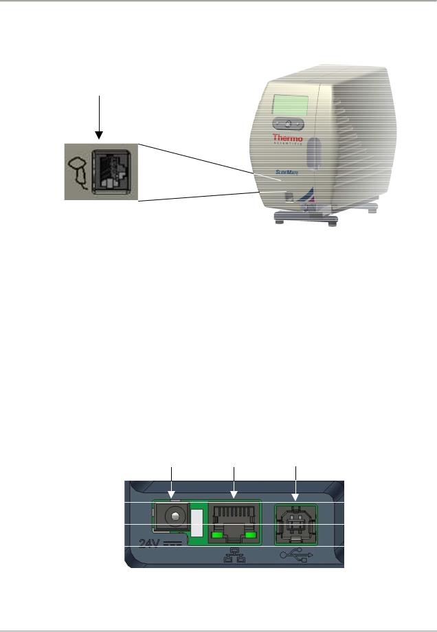
1.1. If using a Barcode Scanner plug it into the connector shown below.
Figure 1 - Barcode scanner connection
1.2.Connect the provided Power supply to the unit. Please make your connections in the following order:
∙Connect your USB cable (optional)
∙Connect your Ethernet /Crossover cable (optional)
∙Plug the power cord into an electrical outlet
∙Plug the other side of the power adapter into the Power Connector shown below
Ethernet USB
Power port port
Connector Connector Connector
Figure 2 - Rear Connectors
SlideMate Operator Guide, Revision 1.20 |
Page 5 |

SlideMate Integration Options
1.3. After power up is complete this screen will be shown, see Figure 3.
Figure 3 - SlideMate user interface
1.4.Press center on the 5-way navigation control button to initialize SlideMate.
To ensure proper operation of the unit it is recommended that you use approved slides, and you verify the slides are not stuck together, as it may be difficult for SlideMate to separate them. Refer to the illustration below for suggestion on how to do this verification.
To prevent contamination of the slides, whenever handling them, protective gloves must be worn!
Look to see that every slide has fallen, and it is in contact with the table surface.
Figure 4 - Slide preparation
Using slides other than the ones recommended,
may cause irreversible damage to the unit.
Please see Appendix A for a list of recommended slides.
SlideMate Operator Guide, Revision 1.20 |
Page 6 |

SlideMate Integration Options
1.5.Route the ribbon through SlideMate unit as shown in the figure below. In the main setup screen use the Load function accessed by the right button (see Figure 9). This allows the ribbon take-up reel to be rotated in the take-up direction by hand.
Figure 5 - Correct Ribbon Routing Procedure
Please note the direction the ribbon feeds off the roll. Figure 5 shows the correct feed direction.
Figure 6 - Incorrect Ribbon Routing Procedure
Using a ribbon other than the one recommended, may cause irreversible damage to the unit.
Please see Appendix B for media part number.
SlideMate Operator Guide, Revision 1.20 |
Page 7 |

SlideMate Integration Options
To fasten the ribbon on the take-up Reel, slide it under one of the two pins (see Figure 6).
When removing the accumulated ribbon simply squeeze with one hand the outer area of the roll and pull out.
Figure 7 – Take-up Reel, close up view
1.6. Load slides in the Input Stack in the orientation shown below.
Use caution when loading slides as the edges may be sharp.
Make sure the frosted side of the slide faces up and it is closest to the LCD screen.
Figure 8 – Loading Slides
SlideMate Operator Guide, Revision 1.20 |
Page 8 |
SlideMate Integration Options
2.SlideMate Interface Menu
2.1.Access the interface menu to choose the information to be printed (see Figure 9). To format the information use Print Img Settings. Refer to section 3 for more details regarding the information about data and text formatting.
Current print information will be displayed in this screen
After choosing |
|
|
|
|
|
After choosing Qtxt |
||
Setup this |
|
|
|
|
|
|
|
this screen will be |
|
|
|
|
|
|
|
||
screen will be |
|
|
|
|
|
displayed |
||
displayed |
|
|
|
|
|
|
||
|
|
|
|
|
|
|
|
|
Figure 9 - Initialization and main menu options
If no Qtext has been entered then the Qtext screen will read No quick txt, see section 3 for a description of the Qtext function.
After scrolling down
Figure 10 - Global
Settings Menu
Figure 11 - Printer
Settings Menu
∙Barcode height value is measured in mm
∙Time and date can be automatically printed
∙If Auto Print is OFF when a raster image is sent to print the operator will be required to press Print
∙If Number of Slides is 0 and Auto Print is ON or OFF the machine will ask for the desired number of slides to be printed
∙If Print Errors is ON print related errors will be displayed
∙Change the Language of the user interface to meet your needs
∙Enter Datamtx Setup to configure the 2D barcode, see section 2.2 for details
∙Top Offset and Left Offset values are in mm. These values work for both machine-rendered and windows-rendered images (Raster, ASCII and Data)
∙Darkness value is shown as percentage. Different slide brands may warrant different darkness settings to produce the highest quality print image
SlideMate Operator Guide, Revision 1.20 |
Page 9 |
SlideMate Integration Options
Figure 12 - Network
Settings Menu
∙If Network is selected (Select Port, Figure 12) prior to power up, SlideMate will automatically start looking for network settings
∙If Network is selected after power up it will be necessary to initiate acquiring of the network settings by simply entering and exiting the network settings menu
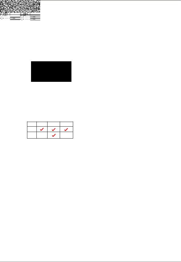
∙Select Port, SlideMate has 3 input ports (Figure 1 and 2)
∙Delimiter, this is the ASCII character that indexes the input data into the next data field
∙End of Data, this is the ASCII character that tells SlideMate that all data is complete for current slide
Figure 13 - Input Device ∙ Data Type, indicates the type of file ready to receive
Menu
(Raster or Data)
Table of supported port/data types combinations:
∙Notice that a punctuation screen is available by pressing the 5-way navigation button, see
Figure 15. Move cursor to upper or lower row and press up or down respectively. In the same manner you return to text screen from the punctuation screen.
SlideMate Operator Guide, Revision 1.20 |
Page 10 |

SlideMate Integration Options
2.2.Upon entering the Datamatrix Setup the following screen will be shown
∙Use the Datamatrix scale parameter to adjust the pixel’s size of the printed 2D barcode. Increasing the scale will enhance the readability of the barcode however it will decrease the number of characters in the barcode, see table below.
∙Datamatrix pos is referenced to the left edge of the slide and the unit of measurement is mm
∙Top quiet zone will provide the specified amount (pixels) of empty rows above the printed 2D barcode. Increasing
Figure 14 - Datamatrix
Setup
the quiet zone will enhance the readability of the barcode however will reduce the printable area.
∙Bottom quiet zone will provide the specified amount (pixels) of empty rows below the printed 2D barcode. Increasing the quiet zone will enhance the readability of the barcode however will reduce the printable area.
NOTE: There are limitations regarding the combinations of the Text Font sixe and the Data Matrix barcode size. See Table Below for more details.
|
Text Line |
|
Maximum Number of Characters in the |
||
Configuration (Font |
2-D Data Matrix Barcode Based on data |
||||
Size and Number of |
|
Type |
|
||
|
lines) |
|
|
|
|
Small |
Medium |
Large |
Numeric |
Alphanumeric |
All |
|
|
|
Characters |
Characters |
Characters |
|
|
|
|
|
(i.e. ‘?’, |
|
|
|
|
|
‘@’, etc.) |
1 |
2 |
0 |
80 |
80 |
80 |
0 |
3 |
0 |
80 |
80 |
80 |
0 |
2 |
1 |
80 |
80 |
80 |
0 |
1 |
2 |
80 |
80 |
80 |
0 |
0 |
3 |
72 |
40 |
34 |
SlideMate Operator Guide, Revision 1.20 |
Page 11 |

SlideMate Integration Options
Figure 15 - Print Image Settings with Print line formatting
SlideMate Operator Guide, Revision 1.20 |
Page 12 |
SlideMate Integration Options
3. Understanding Data Fields and Text Fields
Data fields and Text fields are information storage places.
The difference between the two is that Data Fields are dynamic. It means that they only retrieve the information for the current print cycle and then are cleared. This data comes from an external input device such as a barcode scanner.
Text fields on the other hand store the information until deleted, edited or overwritten. To enter information in Text Fields go to Print Img Settings/Text Fields/Text1 and use the screen keyboard input shown in
Figure 15 to enter text. See the example in the next section where the information is entered via a keyboard, but a scanner could be used as well.
NOTE: If information is typed or scanned while in Print Screen it will be stored in Data Fields.
Qtext is another way of storing information to print. It resembles Text Fields but it’s accessible directly from the Print Screen. Terms most often used can be stored in Qtext for quick access (e.g. Section level or
stain name).
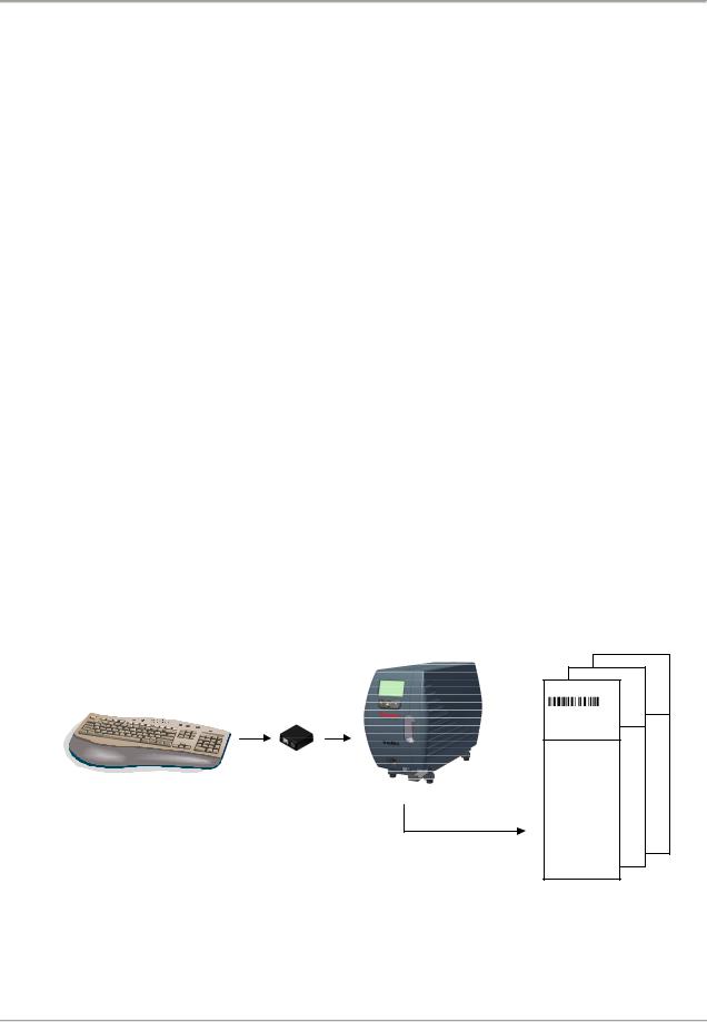
4. Data input fields and text formatting example
To understand how information is stored and formatted we provide the following example. Connect a PC keyboard to the SlideMate unit and type all information you need printed. SlideMate can print a total of five lines (text, barcode or both).
Figure 16 - Example data input and output
SlideMate Operator Guide, Revision 1.20 |
Page 13 |

SlideMate Integration Options
Typed information will be stored in machine’s memory as it is typed. Notice below that all typed information before each comma (delimiter settings, see Figure 13) has been stored in a different Data.
Additional information can be entered in text fields, as shown below:
Figure 17 - Setting up information in text fields
Each Print Line can contain maximum of 24 characters using the Small font. Each line can be formatted using 3 font sizes, Small, Medium, and Large. It can also be converted into barcode
(Code128). Any of the Data Fields can be printed on any of the five Print Lines.
SlideMate Operator Guide, Revision 1.20 |
Page 14 |

SlideMate Integration Options
In the example below, Data 1 is printed at the top of the slide.
For the second line, Data 1 is chosen to be printed again in Code128 barcode.
On the third line, the name of the patient, which was typed after the first comma, will be printed.
Fourth line will print the age and sex of the patient, which was stored in Data Field 3 and 4. This line has been formatted using the Medium Font size.
Last line to print has been formatted with text information (see Figure 17). This entire line will print using the Small Font size.
In this case, a sequence of three slides will be printed and each slide will be identified with its sequence number. Current refers to the current slide printing and Total refers to the total number of slides in the series.
SlideMate Operator Guide, Revision 1.20 |
Page 15 |

SlideMate Integration Options
And finally the choices for print, font size and location will print on the slides:
Notice the 3 vertical bars before the text on the print screen; this indicates the text will be printed as barcode.
Figure 18 - Printed slides’ sequence
5. Using the Keyboard Option for Data Entry and Menu Navigation
To enable the use of a Keyboard, Thermo Fisher Scientific offers an optional Interface Adapter. This adapter also allows simultaneous connections of a Barcode Scanner and a Keyboard to the SlideMate unit. Please see Appendix B for part number. Follow the instructions below for proper connectivity.
5.1. Plug the supplied cable into the connectors as shown in the figure below.
Figure 19 - Keyboard Interface Adapter connection
SlideMate Operator Guide, Revision 1.20 |
Page 16 |
 Loading...