


Thermo Safety Cabinets MSC-Advantage User manual
Operating Instructions
Safety cabinet
MSC-Advantage™
Valid: 11.2006 / 50108599 A
Valid: 02.2007 / 50110565

Operating Instructions Safety Cabinet | MSC-Advantage
Inhaltsverzeichnis
Copyright
These operating instructions are protected by copyright. Rights resulting
thereof, particularly reprint, photomechanical or digital postprocessing or
reproduction, even in part, are only allowed with the written consent of
Thermo Electron LED GmbH.
This regulation does not apply to reproductions for in-plant use.
Trademarks
MSC Advantage is a registered trademark of Thermo Fisher Scientific and
of its subsidiary companies. All other trademarks mentioned in the operating
instructions are the exclusive property of the respective manufacturers.
Thermo Electron LED GmbH
Robert-Bosch-Straße 1
D - 63505 Langenselbold
Germany
2

Operating Instructions Safety Cabinet | MSC-Advantage
Contents
1. General notes ......................................................................................... 6
1.1 Instruction of the operating personnel ........................................... 6
1.2 Applicability of the instructions ...................................................... 7
1.3 Warranty ........................................................................................ 7
1.4 Explanation of symbols ................................................................. 8
1.4.1 Symbols used in the operating instructions ............................. 8
1.4.2 Symbols on the device ............................................................. 9
1.5 Use of the device ......................................................................... 10
1.5.1 Correct use ............................................................................. 10
1.5.2 Incorrect use ........................................................................... 10
1.6 Standards and safety regulations ................................................ 11
2. Delivery ................................................................................................. 12
2.1 Standard components .................................................................. 12
2.2 Acceptance inspection ................................................................. 12
2.3 Transport security lock and device packaging ............................ 12
3. Installation ............................................................................................ 13
3.1 Ambient conditions ...................................................................... 13
3.2 Room ventilation .......................................................................... 14
3.3 Correct location............................................................................ 14
3.4 Installation in series ..................................................................... 14
3.5 Transport...................................................................................... 15
4. Description of the device .................................................................... 16
4.1 Overall view ................................................................................. 16
4.2 Safety system .............................................................................. 18
4.3 Filter system ................................................................................ 19
4.4 Operating and display elements .................................................. 20
4.5 Sample chamber access ............................................................. 21
4.6 Device interfaces ......................................................................... 22
4.7 Sample chamber illumination ...................................................... 24
4.8 UV lamp unit ................................................................................ 24
4.9 Working area ............................................................................... 24
5. Start-up.................................................................................................. 25
5.1 Initial operation ............................................................................ 25
5.2 Installing the device and accessories.......................................... 25
5.3 Unlocking the transport protection .............................................. 26
5.4 Levelling the cabinet .................................................................... 26
5.5 Power supply connection ............................................................ 27
5.6 RS 232 interface connection ....................................................... 28
5.7 Installation test ............................................................................. 29
6. Handling and control ........................................................................... 30
6.1 Operating panel ........................................................................... 30
6.1.1 Functional units ...................................................................... 30
6.1.2 Display during calibration routine ........................................... 31
6.1.3 Display during UV disinfection ............................................... 31
6.1.4 Failure messages ................................................................... 32
6.2 Device start-up ............................................................................. 32
6.3 Description of the operating modes ............................................ 33
7. Operation .............................................................................................. 35
7.1 Hygiene preparations for the sample chamber ........................... 35
7.2 Loading the sample chamber ...................................................... 35
7.3 Response to failure messages .................................................... 35
7.4 Work rules .................................................................................... 36
3

Operating Instructions Safety Cabinet | MSC-Advantage
Contents
8. Shut-down............................................................................................. 37
8.1 Interrupting an operation ............................................................. 37
8.2 Shutting the device down ............................................................ 37
9. Cleaning and decontamination .......................................................... 38
9.1 Decontamination procedure ........................................................ 38
9.2 Wipe/spray disinfection................................................................ 38
9.3 UV disinfection after a wipe/spray disinfection ........................... 40
9.3.1 UV disinfection using the integral UV lamp ............................ 40
9.3.2 UV disinfection using a mobile UV device (optional) ............. 40
9.3.3 Changing UV disinfection time ............................................... 40
9.4 Disinfection with formaldehyde ................................................... 41
9.5 Cleaning the exterior surfaces..................................................... 41
9.6 Cleaning the front window ........................................................... 41
9.7 Cleaning the floorpan .................................................................. 42
9.8 Cleaning the protective grid ......................................................... 42
10. Maintenance ......................................................................................... 43
10.1 Inspection .................................................................................... 43
10.2 Service ......................................................................................... 43
10.2.1 Sample chamber illumination ................................................. 44
10.2.2 Optional UV lamps.................................................................. 44
10.3 Retrofitting and repairs .............................................................. 44
11. Disposal ................................................................................................ 45
11.1 Disposal procedure ..................................................................... 45
12. Technical data ...................................................................................... 47
13. Device log ............................................................................................. 51
14. Certificate of decontamination ........................................................... 52
4

Operating Instructions Safety Cabinet | MSC-Advantage
Figures
Fig. 1 Device arrangement in the operating room .................. 14
Fig. 2 Lift points ....................................................................... 15
Fig. 3 Overall view ................................................................... 17
Fig. 4 Filter system with downflow and exhaust air filter ........ 19
Fig. 5 Operating and display elements ................................... 20
Fig. 6 Sample chamber opening ............................................. 21
Fig. 7 Supply interfaces ........................................................... 22
Fig. 8 UV lamp unit .................................................................. 24
Fig. 9 Working area on the workplate, armrests ..................... 24
Fig. 10 Stand installation ........................................................... 25
Fig. 11 Unlocking the transport protection ................................ 26
Fig. 12 RS 232 interface ............................................................ 28
Fig. 13 Operating panel I ........................................................... 30
Fig. 14 Operating panel II .......................................................... 31
Fig. 15 Display upon start-up .................................................... 32
Fig. 16 Sitting posture ............................................................... 36
Fig. 17 Protective grid segment ................................................ 42
Fig. 18 UV lamp replacement .................................................... 44
5

Operating Instructions Safety Cabinet | MSC-Advantage
1. General notes
The following are the addresses of the international Thermo
Fisher Sales Organisations.
Postal address Germany
Thermo Electron LED GmbH
Robert-Bosch-Straße 1
D - 63505 Langenselbold
Inquiries from Germany
Phone
Sales 0800 1 536376
Service 0800 1 112110
Fax
Sales/Service 0800 1 112114
EMail
info.labequipment.de@thermofisher.com
Enquiries from Europe, Middle East
and Africa
Tel. + 49 (0) 6184 / 90-6940
Fax + 49 (0) 6184 / 90-7474
EMail
info.labequipment.de@thermofisher.com
Postal address USA
Thermo Fisher Scientific
275 Aiken Road
Asheville, NC 28804
USA
Enquiries from North America
Phone +1 800-879 7767
Fax +1 828-658 0363
EMail
info.labequipment.de@thermofisher.com
Enquiries from Latin America
Phone +1 828-658 2711
Fax +1 828-645 9466
EMail
info.labequipment.de@thermofisher.com
Enquiries from Asia Pacific
Phone +852-2711 3910
Fax +852-2711 3858
EMail
info.labequipment.de@thermofisher.com
1.1 Instruction of the operating personnel
These operating instructions describe the safety cabinet
• MSC Advantage
and apply to the models MSC 1.2 and MSC 1.8.
The safety cabinet has been manufactured in keeping with the latest technological developments and has been tested before delivery for its correct function. It may, however, present potential hazards if it is not used according to the
intended purpose or outside of operating parameters. Therefore, the following
procedures must always be observed to prevent accidents:
• The safety cabinet must be operated only by trained and authorized personnel.
• For any operation of this device, the operator must prepare clear and concise written instructions in the language of the operating and cleaning personnel based on these operating instructions, applicable safety data sheets,
plant hygiene guidelines, and technical regulations, in particular:
• which decontamination measures are to be applied for the cabinet and
accessories,
• which protective measures apply while specific agents are used,
• which measures are to be taken in the case of an accident.
• Repairs to the device must be carried out only by trained and authorized expert
personnel.
6

Operating Instructions Safety Cabinet | MSC-Advantage
1. General notes
1.2 Applicability of the instructions
• The contents of the operating instructions are subject to change without
further notice.
• Concerning translations into foreign languages, the German version of these
operating instructions is binding.
• Keep these operating instructions close to the device so that safety instructions
and important information are always accessible.
• Should you encounter problems that are not detailed adequately in these operating instructions, please contact Thermo Fisher Scientific immediately for
your own safety.
1.3 Warranty
Thermo Fisher Scientific warrants the operational safety and functions of the safety cabinet only under the condition that:
• the device is operated and serviced exclusively in accordance with its intended
purpose and as described in these operating instructions,
• the device is not modified,
• only original spare parts and accessories that have been approved by Thermo
Fisher Scientific are used,
• inspections and maintenance are performed at the specified intervals,
• an installation test is performed prior to the initial operation of the device and
that a repeat test is performed on the occasion of all inspections and repairs.
The warranty is valid from the date of delivery of the device to the operator.
7
Operating Instructions Safety Cabinet | MSC-Advantage
1. General notes
1.4 Explanation of symbols
1.4.1 Symbols used in the operating instructions
WARNING!
is used if non-observance may cause serious
or even lethal injuries.
CAUTION!
is used if non-observance may cause medium
to minor injuries or damage.
NOTE!
is used for hints and useful information.
RECYCLING!
Valuable raw materials can be reused.
Warning against electric shock.
8
1. General notes
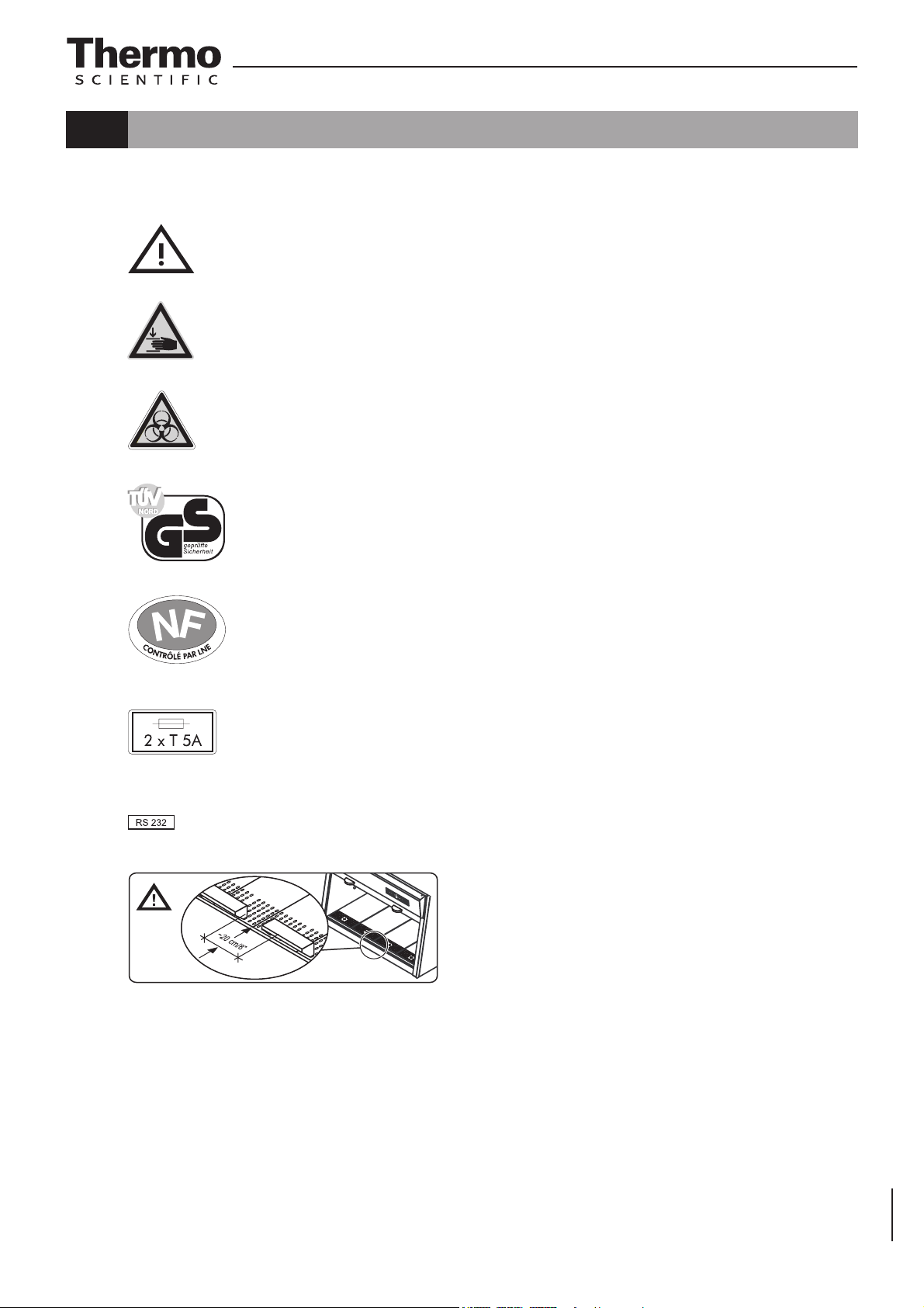
1.4.2 Symbols on the device
Observe operating instructions (switchbox ceiling)
Warning against hand injuries (device side walls)
Biohazard (left front section of device)
Operating Instructions Safety Cabinet | MSC-Advantage
Checked safety (cover light dome)
Norme Française / NF - Postes de Sécurité Microbiologique
T5A note (sample chamber fusing)
RS 232 interface (upper side of plenum panel)
Armrest installation
(right side of light dome)
9

Operating Instructions Safety Cabinet | MSC-Advantage
1. General notes
1.5 Use of the device
1.5.1 Correct use
The safety cabinet is a laboratory device for installation and operation in microbiological and biotechnical laboratories of safety levels 1, 2, and 3. It has been
designed as a Class II microbiological safety cabinet, in accordance with EN
12469 / 2000.
Depending on the hazard level of the agents involved, the operator must prepare in writing appropriate decontamination procedures for the device and the
accessories used in the sample chamber.
Prior to the initial operation of the cabinet, the operator must perform an installation
test. The test result must be documented by a test report. The cabinet must only
be released for operation if it is in compliance with the operating parameters specified by Thermo Fisher Scientific.
After any changes to the installation conditions and after any modification to the
technical system, a repeat test must be performed and the test result must be
documented by a test report that shows that all operating parameters are in compliance with those specified by Thermo Fisher Scientific.
1.5.2 Incorrect use
The safety cabinet must not be used in laboratories that do not comply with the
requirements of safety levels 1, 2 or 3.
The device must not be operated as a Class II safety cabinet if:
• no repeat test is performed after changes to the installation conditions or after
modifications to the technical system,
• the alarm system of the device has issued a failure message and the cause for the failure has not been repaired.
The alarm system must not be tampered with or disabled. If alarm system components heve been removed or disabled for service or repairs, the device must
only be released for operation if all alarm system components are functioning
properly again.
The filters installed in the device are not capable of separating gaseous substances. Therefore, never store or process gases or gas-releasing substances
in the device:
• who in quantity or concentration are toxic,
• if a reaction with other substances may result in hazardous toxic concentrations
or formation of toxic gases,
• that may form combustible or explosive mixtures in combination with air.
10

Operating Instructions Safety Cabinet | MSC-Advantage
1. General notes
1.6 Standards and safety regulations
The device complies with the safety requirements of the following standards and
directives:
• NF 095 Rev3.2006 / NF - Postes de Sécurité Microbiologique
• IEC 61010-1:2001
• EN 61010-1:2001
• EN 12469:2000
• DIN EN 61326-1:2004-05
• Low Voltage Directive 73/23 EWG
• EMC Directive 89/336 EWG
11

Operating Instructions Safety Cabinet | MSC-Advantage
2. Delivery
2.1 Standard components
Delivery for the safety cabinet includes the following:
• safety cabinet (without stand)
• armrests
• device documentation:
– operating instructions
– factory test report
Optional components and accessories are listed as separate items in the delivery document.
2.2 Acceptance inspection
After the device has been delivered, immediately check the device:
• for completeness,
• for possible damage.
If the delivery is incomplete or if you detect any transport damage to the
device, contact the forwarding agency and Thermo Fisher Scientific immediately.
2.3 Transport security lock and device packaging
A transport security lock protects the device counterweight during transport.
Protective packagings protect the floorpan, the front window, and the workplate
segments. To remove the transport security lock and the protective packagings,
please refer to the enclosed installation instructions and to Sections 5.2 and 5.3
of these instructions.
12

Operating Instructions Safety Cabinet | MSC-Advantage
3. Installation
3.1 Ambient conditions
The operational safety and correct function of the device depend on the location where it is to be operated. The safety cabinet must be operated only at locations that meet the ambient conditions listed below.
Location requirements:
• The electrical system of the device has been designed for an operating height
of up to 2000 m above sea level.
• The mains power supply outlet should be out of casual reach to prevent accidental shut-off. Ideally, the outlet should be installed above the safety
cabinet.
The outlet must be accessible to authorized personnel only. It constitutes,
together with the power cable plug, the disconnection device for all poles.
• The flooring of the location must be adequately strong and not flammable.
• The stand must ensure a sufficient load-bearing capacity (twice the device
weight).
• The room in which the device is installed must be of adequate height. For
devices that are not connected to an exhaust system, the distance between
the exhaust air opening at the device ceiling and the room ceiling must be
at least 200 mm (8 in).
• The location must be equipped with an appropriate ventilation system
(see Section 3.2.).
• The temperature within the room must be between 15 °C and 40 °C
(49 °F and 104 °F).
• The relative humidity in the vicinity of the device must not exceed 90 %.
NOTE - Ambient conditions!
If ambient conditions vary from those described above, please contact Thermo Fisher
Scientific for assistance in installing the device.
NOTE - Temporary storage!
If the device is stored only temporarily (up to
four weeks), the ambient temperature may be
between -20 °C and +60 °C (-4 °F and +140 °F)
at a relative air humidity of up to 90 %. For longer storage periods, the location requirements
apply.
13
Operating Instructions Safety Cabinet | MSC-Advantage
3. Installation
3.2 Room ventilation
The room ventilation should preferably be a ventilation system
that complies with the national requirements for the application.
• The inlet air and exhaust air openings of the room ventilation
must be located so that drafts are prevented from impairing
the function of the safety cabinet air system.
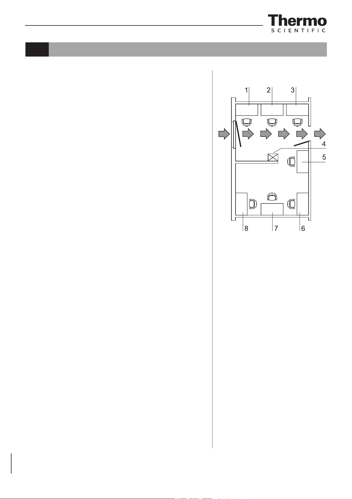
3.3 Correct location
Choose a draft-free location where the safety cabinet does not
interfere with the plant traffic.
Fig. 1: This figure shows preferred locations for safety cabinets and unsuiable locations that are not in accordance with
the safety requirements.
Unsuitable locations: The locations [1], [2], and [3] are not
suitable because they are exposed to drafts from windows and
doors.
Location [5] is unsuitable because it is within range of plant traffic
and within the exhaust air range of a ventilation system [4].
Preferred locations: The locations [6], [7], and [8] are correct
because they are in a draft-free section of the room and not
exposed to plant traffic.
A counterweight at the device backpanel moves synchronously
with the vertical movement of the front window. To prevent the
counterweight from jamming, the device backpanel should be
as close to the wall as possible.
Fig. 1
Device arrangement in the
operating room
3.4 Installation in series
When several devices are to be installed in series, please observe the following:
• Make sure that vibrations cannot be transferred between
adjacent devices.
• Exterior surfaces of the cabinets must always be accessible
for cleaning and disinfection.
14
3. Installation
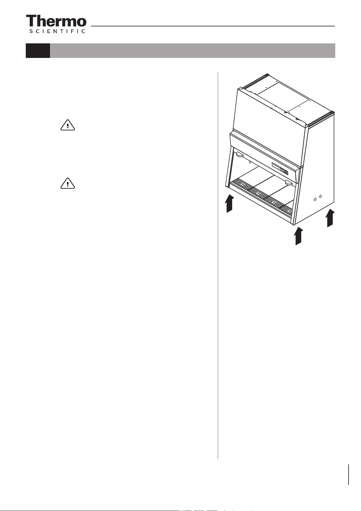
3.5 Transport
Fig. 2: To prevent tilting, always transport the device using a
suitable carrier, even for a transport within a building, and separate it from the stand (see Section 5.2).
CAUTION – Lift points!
For transport, lift the device only at the lift
points shown in Figure 2.
Do not allow the weight of the cabinet to rest
on the floorpan!
CAUTION – Crushing hazard!
Operating Instructions Safety Cabinet | MSC-Advantage
The weight of the front window is counterbalanced by the counterweight (at the rear of the
device).
The device must not be transported unless the
counterweight has been locked.
• Install the four lockscrews (see Section 5.3).
Fig. 2
Lift points
15

Operating Instructions Safety Cabinet | MSC-Advantage
4. Description of the device
4.1 Overall view
• Fig. 3: Plenum assembly [3] with plenum for downflow blower [18] and plenum
for exhaust air blower [19]. The downflow filter and the exhaust air filter are
installed immediately to the pertaining plenum. The exhaust air is discharged to the exterior of the device through an opening [20].
The plenum assembly is concealed behind a cover [17].
• Switchbox [2] with power supply unit and power supply cable [1]. The top
of the device contains an RS 232 connection [22] for a PC and two fuse
holders [21].
• Light dome [4] for the sample chamber illumination unit, equipped with one
fluorescent tube (model MSC 1.2) or two fluorescent tubes (model MSC 1.8).
The optional, device-integral UV lamp is installed to the ceiling at the front
section of the sample chamber.
• Operating panel [5] with function keys and indicators.
• Front window [7] with two handles [6].
• Bushings [8] at the side panels (two on each side) into which media valves
[10] can be installed. The covers must not be removed but only broken through at the rupture joint.
• Stand [9] (optional).
• Workplate segments [12] with 2 armrests [13]. A one-pice workplate and
special workplates are available as optional accessories.
• Internal outlets [14] for the power supply of accessories (optionally, one of
the outlets can be equipped with an adapter [16] for mobile UV devices).
• Test hoses for the downflow unit [15] at the left side of the sample chamber
and for the exhaust air unit [11] at the right side of the sample chamber.
NOTE – Test hoses!
Do not remove the caps of the two test hoses
for checking downflow and exhaust air.
16