

Thermo Safety Cabinet Class 2 User manual
GB
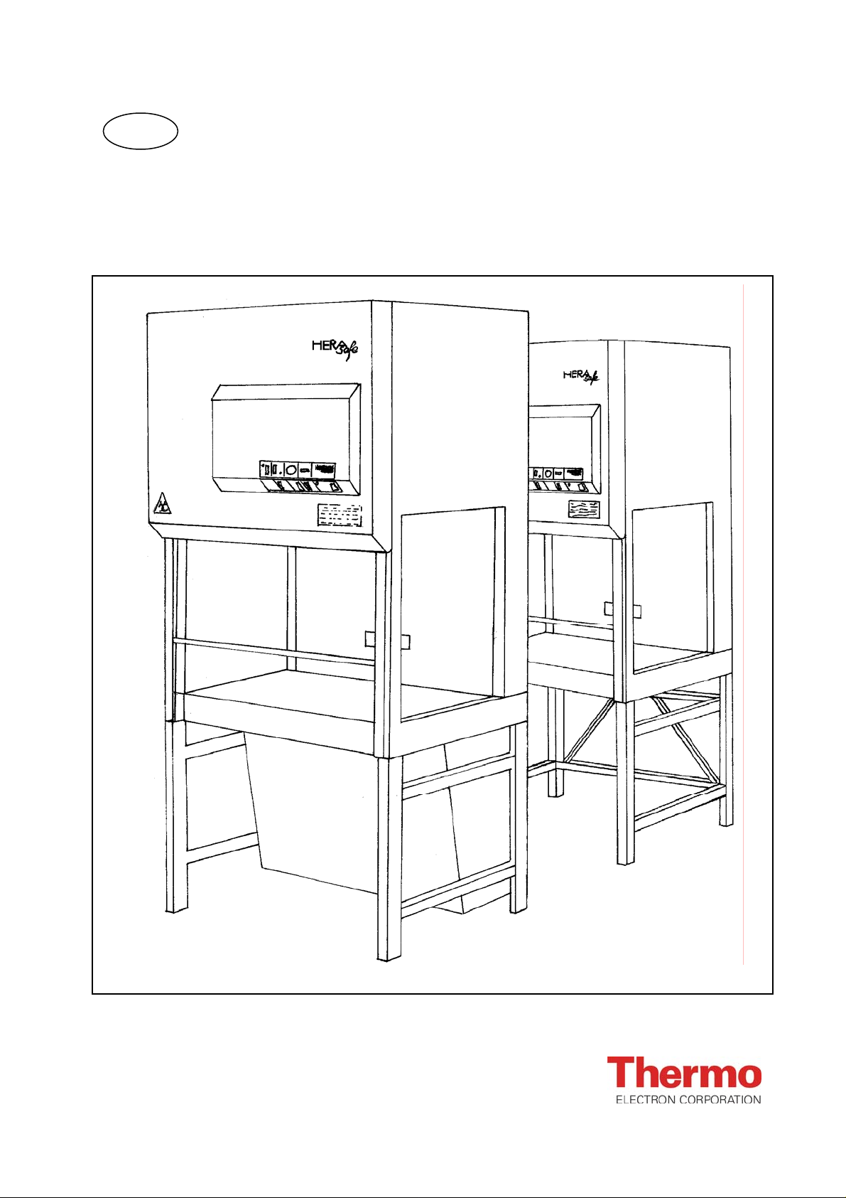
Class 2
Safety Cabinets
Operating instructions
Valid: 09.2005 / 50047299 C
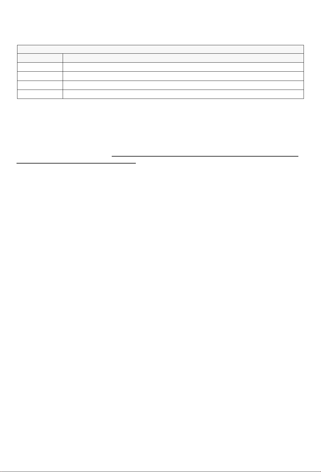
These operating instructions apply to the following unit equipment levels:
Model Equipment
HS Units with intake protection pre-filters
HSP Units with HOSCH pre-filters
HSPC Units with activated charcoal pre-filters
HS. . . ./85 Units with increased interior height
Neither these instructions nor any part thereof may not be reproduced or distributed without the express written
approval of Thermo Electron LED GmbH.
This version applies to operating instructions for series production safety workbenches.
These operating instructions may be expanded to include accessories.
Various sections of this manual may only be copied for the internal use of the operator, e.g., for person-
nel safety and accident prevention training. These sections are indicated in the contents.
Thermo Electron LED GmbH assumes no liability or responsibility for the suitability of the units for a particular purpose aside from those listed in the section dealing with the unit's areas of application.
We reserve the right to make changes to the content of these operating instructions at any time and without prior notification.
For all translations into foreign languages, the original German version of these operating instructions
is binding.
Published: 09.2005
Subject to fee.
Trademarks
HERAsafe ® and the term "Heraeus" are registered trademarks of Thermo Electron LED GmbH.
Any other trademarks mentioned are the exclusive property of the manufacturers in question.
© Thermo Electron LED GmbH, 63505 Langenselbold, Germany
2/27 50 047 299

Below is a list of the international Thermo marketing organizations.
Postal address Germany
Thermo Electron LED GmbH
D – 63505 Langenselbold
Robert-Bosch-Strasse 1
Enquiries from Germany
Phone
Sales 0800 1 536376
Service 0800 1 112110
Fax
Sales/Service 0800 1 112114
E-Mail
info.labequipment.de@thermo.com
Enquiries from Europe, Middle East
and Africa
Phone + 49(0) 6184 / 90-6940
Fax + 49(0) 6184 / 90-7474
E-Mail
info.labequipment.de@thermo.com
Enquiries from Asia Pacific
Postal address USA
Thermo Electron Corporation.
275 Aiken Road
Asheville, NC 28804
USA
Enquiries from North America
Phone + 1 800-879 7767
Fax + 1 828-658 0363
E-Mail
info.labequipment@thermo.com
Enquiries from Latin America
Phone + 1 828-658 2711
Fax + 1 828-645 9466
E-Mail
info.labequipment@thermo.com
Phone + 1 852-2711 3910
Fax + 1 852-2711 3858
E-Mail
info.labequipment@thermo.com
Internet: www.thermo.com
2a
WEEE Compliance:
This product is required to comply with the European Union`s Waste Electrical & Electronic
Equipment (WEEE) Directive 2002/96/EC. It is marked with the following symbol:
Thermo Electron has contracted with one or more recycling/disposal companies in each EU
Member State, and this product should be disposed of or recycled through them. Further
information on Thermo Electron`s compliance with these Directives, the recyclers in your
country, and information on Thermo Electron products wich may assist the detection of
substances subject to the RoHS Directive are available at www.thermo.com/WEEERoHS.
2b

CONTENTS
CONTENTS Page
GLOSSARY ................................ 2
CONTENTS ................................ 3
1. OVERVIEW ................................. 4
Control Panel ................................ 4
Explanation of Control Panel Elements ........ 5
Key to Symbols .............................. 5
2. NOTES CONCERNING ENVIRONNEMENTAL
SAFETY ....................................6
Disposal of Shipping Packing Material ......... 6
Disposal of Used Equipment .................. 6
Disposal of Used Filter Elements .............. 6
Energy Consumption ......................... 7
- Cirrculating air mode ....................... 7
- Exhaust mode .............................. 7
3. SAFETY NOTES ............................ 8
Stickers ...................................... 8
Abbreviated operating instructions ............ 8
Safety Notes ................................. 8
(SUMMARY EXCLUDED FROM COPYING PROHIBITION
WHEN USED FOR SAFETY INSTRUCTION)
Operating Instructions ....................... 10
Unit Log ..................................... 10
Test Chamber Power Sockets ................ 10
4. DEVICE DESCRIPTION ....................10
Application Area ............................. 10
Unit Construction ............................ 11
Operating Principle .......................... 12
Safety Equipment ........................... 13
- Power switch with key lock
(Function Selection Switch) ................ 13
- Air monitoring ............................. 13
- Fuel gas shutoff (option) ................... 13
- Front window monitoring ................... 13
- Front window - sealing ..................... 13
- UV lock (option) ........................... 14
- Lowered working bench (option/accessory) . 14
- Flow interrupter for connection to the
laboratory´s ventilation system (accessory) . 14
- Second exhaust filter element (accessory) .. 14
Connection to Laboratory Exhaust Systems .. 18
6. OPERATION ..............................19
Safety check, initial startup .................. 19
- Prior to Startup ............................ 19
Starting up the safety cabinet ................ 19
- Work / operating interruptions .............. 19
- UV disinfection mode ...................... 20
Working Guidelines ......................... 20
Problems ................................... 21
Taking the unit out of service ................ 21
7. MAINTENANCE ............................22
Routine Maintenance Tasks ................. 22
- Cleaning .................................. 22
Replacing Electrical Parts ................... 22
Filter Replacement .......................... 22
- General Information ....................... 22
- Circulation or exhaust filter replacement .... 23
- Intake screen replacement ................ 23
- Intake Protection Replacement (HS) ....... 23
- Prefilter replacement (HSP) ................ 23
Authorized Replacement Parts ............... 24
Authorized Accessories ...................... 24
8. TECHNICAL DATA .........................25
Geometry ................................... 25
Weights, Performance ....................... 26
Electrical Values ............................ 26
Technical ventilation ......................... 26
Filter Technology ............................ 27
Noise Generation ............................ 27
Illumination Strength ........................ 27
Ambient conditions .......................... 27
5. SETUP AND INSTALLATION ...............15
Transport ................................... 15
Setup Location .............................. 15
Room Ventilation ............................ 15
Setup ...................................... 16
Spacing ..................................... 16
Connections ................................. 16
- Power supply .............................. 16
- Fittings (accessory) ........................ 17
- Fuel gas shutoff connection / nnection to
external monitoring systems (Option) ....... 17
Sound Dampening ........................... 18
Version: 02.1999 50 047 299 c 3/27
1. OVERVIEW
The safety of this unit with respect to persons, the environment, and the material being processed depends to a great extent on the behavior of those working with the unit.
However, even safe operation cannot rule out risk, particularly with respect to the health of personnel.
This residual risk depends on the work being performed in each instance.
These operating instructions contain important information concerning your safety, the setup
and installation of the unit, as well as for its operation and maintenance !
Please read these instructions carefully before operating these units. Follow all instructions in
order to avoid problems that may result in damage, in particular, in damage to the user's health.
ALWAYS:
Wear protective gear in accordance with any applicable regulations and suited to the degree of risk in-
volved with the task at hand
(clothing, gloves, protective glasses ...).
Implement and follow appropriate hygienic measures.
Each person is responsible for his or her own personal safety and health.
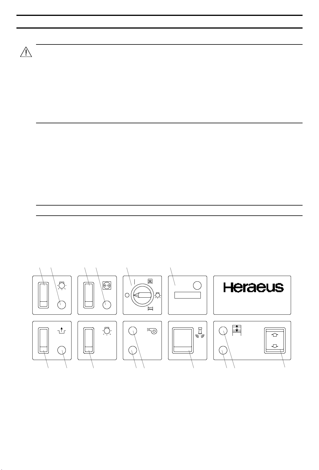
Control Panel
All switches necessary for operation together with all optical and acoustic signaling elements indicating
operation and faults are located on the control panel:
Figure 1/1: Control panel
12 13 14 15
UV
1 2
UV
h
Made in Germany
6 5 48 791011
3
4/27 50 047 299 c Version: 02.1999
1. OVERVIEW
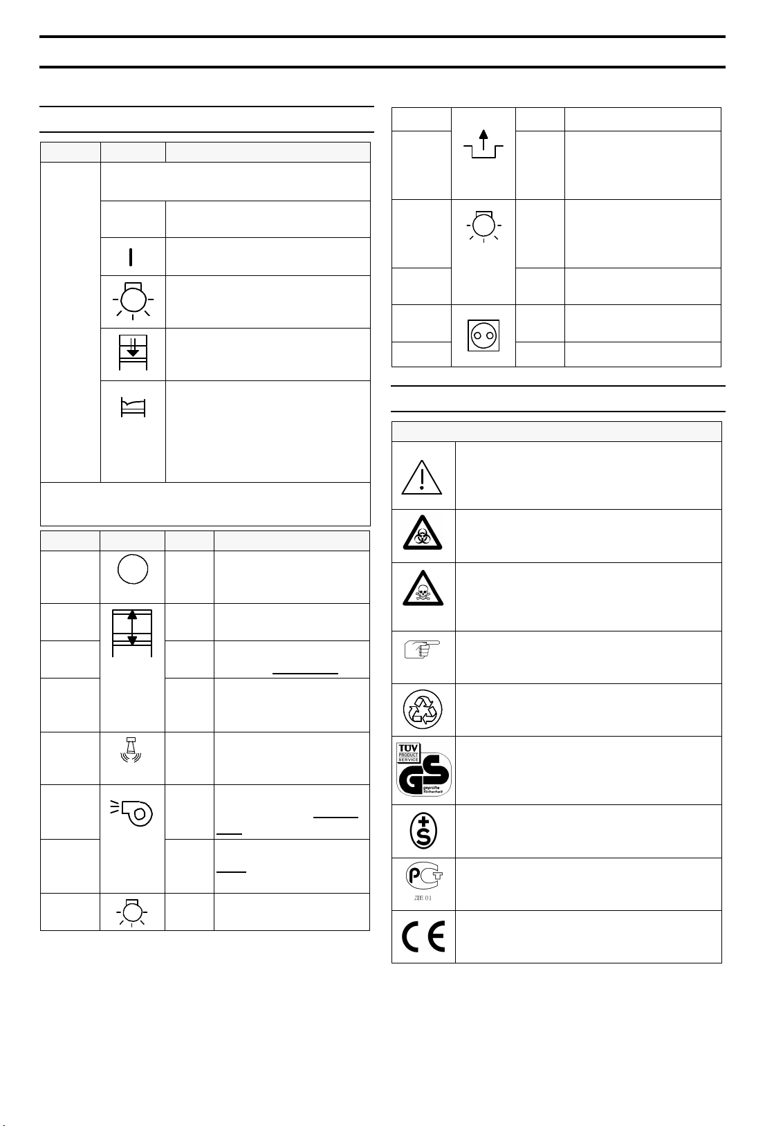
Explanation of Control Panel Elements
Item No. Symbol Message / Comment
Power switch / Function selection
switch with key lock:
Unit OFF
O
Unit ON:
1
UV
Note: The key can be removed and held by the responsible operator,
regardless of the switch position, in order to prevent accidental or
unauthorized switch use.
Item No. Symbol Signal Message / Comment
2
3
4
5
6
7
8
9
Operation / Normal setting
Unit ON:
Operation with UV surface sterilization irradiator (option)
Unit ON:
Close front window (in addition
to command key)
Unit ON:
Ventilation OFF, power outlets
and interior lighting ready
It is not possible to work
safely with pathogenic material.
h
White Window in operating
Red View port not in opera-
Green Ventilation system ope-
Red Ventilation system
Hours of operation
counter, e.g., for machine log maintenance.
Raise/lower front window key
position, Operation
ting position, OPERATI-
ON NOT SAFE
Acoustic warning signal
response button
rating properly, Opera-
tion
, OPERATION
fault
NOT SAFE
Test chamber light ON /
OFF switch
10
11
12
UV
13
14
15
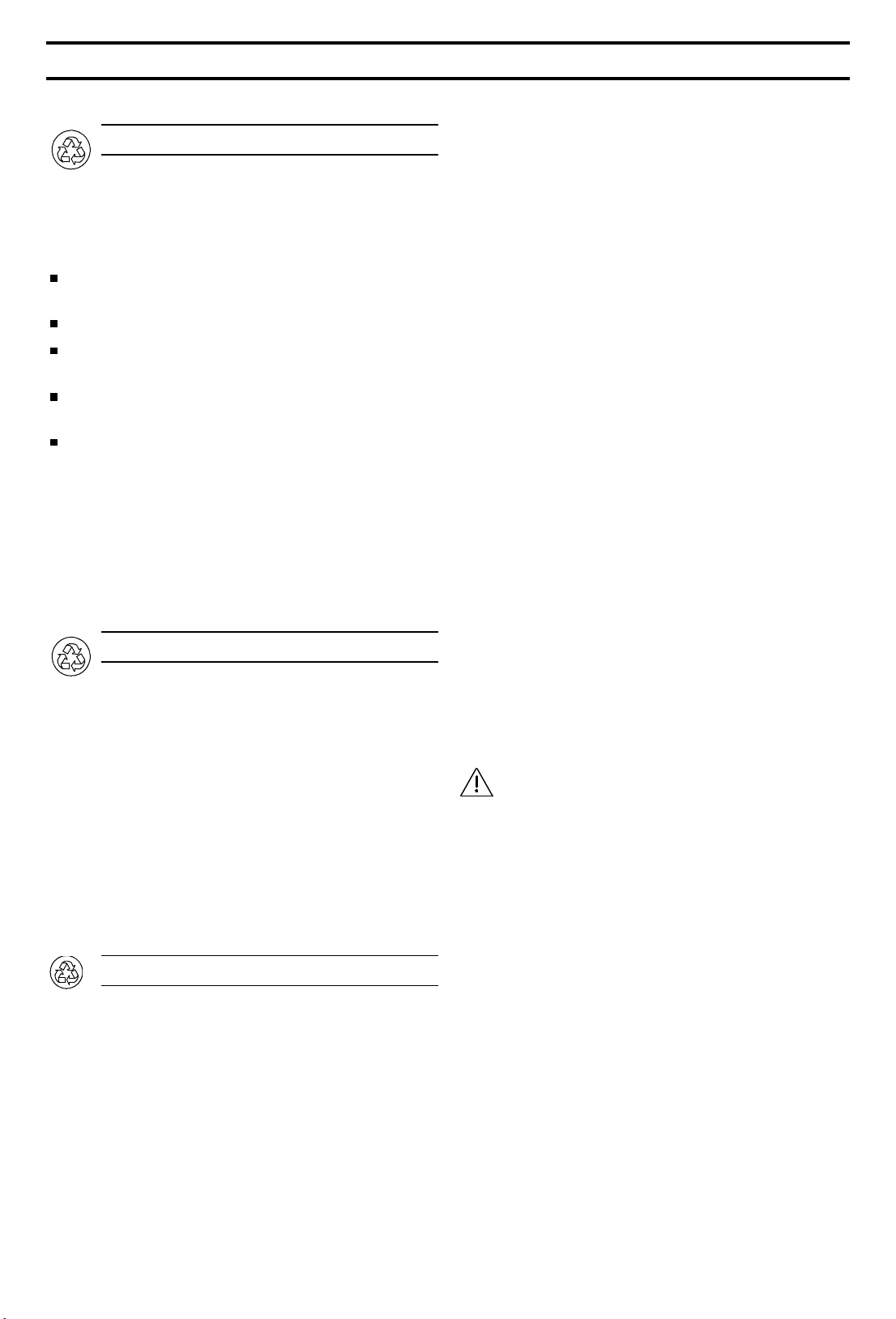
Key to Symbols
Warnings / Notes / Quality marks
Chapters and sections within the operating instructions that are relevant to safety
matters are indicated by this symbol.
Biohazard warning !
On the unit, this symbol warns personnel
against accidental use.
Toxic material warning !
- cytostatic agents On the unit, this symbol warns personnel
against accidental use.
Note providing information on optimum
utilization of the unit.
Note concerning regulated disposal /
reclamation of raw materials.
Symbol indicated safety tested in accord.
with DIN 12950, Part 10/10.1991 and DIN
12 980. Applies to tested device versions
with standard equipment.
Swiss safety certification seal, awarded by
the Eidgenössische Starkstrominspektorat
GOST R conformity certification for devices exported to the Russian Federation
EU symbol confirming conformity with all
relevant European guidelines (nameplate)
Yellow Release active
Release key (option,
e.g., release error message system, magnetic
valve, etc.)
Started timed UV operation timer key
(approx. 60 min) (option)
Yellow UV irradiator ON (opti-
on)
sockets ON / OFF
switch
white sockets ON
Version: 02.1999 50 047 299 c 5/27
2. NOTES CONCERNING ENVIRONMENTAL SAFETY
Disposal of Shipping Packing Material
The packaging is designed to protect the unit against
shipping damage. Aside from the purely technical aspects of shipping, the packaging materials have been
selected with environmental and disposal concerns in
mind, and are recyclable.
The corrugated cardboard employed is made primarily from recycled paper.
Plastic molded parts (Styrofoam) are free of CFCs.
Wood frames and pallets are made of recycled
wood and are untreated.
The polyethylene foil (PE) is made from partially re-
cycled material.
The strapping is made of polypropylene (PP).
Returning the packaging material to the material
circuit saves on raw materials and reduces waste. In
general, packaging material can be returned to your
dealer.
If you will be disposing of the packaging material
yourself, please contact your local government for
the name of the nearest recycling center.
Disposal of Used Equipment
Prior to their proper disposal, any equipment employed for microbiological work must be thoroughly
disinfected and cleaned. An appropriate confirmation
of this is to be included with the equipment being disposed of.
Used equipment contains valuable materials. You
should not simply take an old unit to the nearest
dump or land fill, but should contact your local government department with respect to the required
disinfection/cleaning procedures and the possibility of
recycling some or all device components and materials.
Disposal of Used Filter Elements
The service life of the filter elements depends primarily on the type of work being performed, the cleanliness of the environment in the are in which the unit is
located, and the device construction.
If the filters must be replaced during operation, the
type and extent of possible contamination must be
considered. Depending on the type and degree of
usage, adequate safety measures for the proper disposal of used filters must be in place prior to replacement.
Only you, as the operator can determine the type
and degree of possible environmental stress, possibly
by also referring to the unit handbook.
In cases of microbiological contamination, the filter
elements must undergo suitable decontamination
measures (sterilization or, at least, disinfection) in order to make them non-hazardous. The proper performance of the selected method is to be confirmed in
writing, and this document is to accompany the filter
elements being disposed of.
The most widely accepted procedure for this is total
room disinfection with formaldehyde vapor, followed
by neutralization with ammonia vapor. Follow all
applicable federal, state, and local ordinances when
carrying out this process (in Germany: TRGS 522).
As a rule, the filters are passivated after this disinfection procedure. There is practically no risk of
contamination with filters employed for safety class 1
and 2 work. For filters employed for safety class 3
work, an additional sterilization step by means of autoclaving the broken up filter material may represent
an additional, practical measure.
Filters treated in this manner can be viewed as domestic waste and can be disposed of accordingly.
The filters can be disassembled for the separate disposal of the filter medium (residual waste) and the
aluminum frames. The modalities of the appropriate
disposal methods may need to be separately worked
out within the context of overall waste management.
For the remainder, all applicable federal, state, and
local ordinances must be adhered to (in Germany:
BImSchG, AbFG ...)
Contaminated filter elements are always to
be treated in the same manner as any other
infectious waste generated by the laboratory.
- CAUTION -
Thermo warns against irresponsible surrender of
possibly dangerous filter waste to persons without the
necessary hazardous waste transport certificates and
permits for the disposal of hazardous waste material.
As the originator, you are responsible for this
waste material.
Noncompliance with the regulated procedures for
waste disposal may make you liable for subsequent
damages.
6/27 50 047 299
2. NOTES CONCERNING ENVIRONMENTAL SAFETY
Should you encounter problems in disinfecting - and
thus in neutralizing - the filter elements in question,
please contact us for assistance.
Our Service Department will be happy to present you
with an appropriate offer.
If, aside from the microbiological contamination, the filter elements are expected to
also contain other contaminants (e.g., chemical, toxic, radioactive ...), appropriate
steps must be taken to deal with these prior to disposal of the elements.
Particularly in the case of filter waste that may contain cytostatic agents, it must be treated as hazardous material and be disposed of accordingly.
Energy Consumption
The unit has been designed for continuous operation in order to minimize the risk of contamination.
The ability of the filters to retain materials is only
guaranteed when the unit is operating, that is, when
air is flowing across the filter elements.
Once work in the test chamber has been completed,
the front window can be sealed. The unit then operates in a power-saver mode and is practically si-
lent.
Since the front window is completely sealed in this
mode, it is practically impossible for aerosol materials
in the test chamber to be dispersed into the surrounding atmosphere.
In this operating mode and depending on the ambient
temperature in the setup area, the safety cabinet's interior temperature may increase by up to 10 °C in
this operating mode.
You should therefore never shut the ventilation system off, immediately after completing your work,
so that any untrapped material can still be captured. We recommend waiting approx. 20 minutes of
run-out or reduced continuous operation.
If work is to be interrupted for any length of time,
always turn the test chamber lights out in order to
reduce the unit's energy consumption.
Depending on the agents being processed and their
release in the test chamber, you can also completely
shut down the unit, if it is sealed.
Circulating air mode:
To prevent unnecessary increases in the energy required to heat the laboratory area, we recommend
operating the unit in the circulating air mode. As a
rule, laboratories with a safety classification of L 1
and L 2 do not need to implement any additional
measures to do this.
For laboratories with a safety classification of L 3, a
second exhaust filter (AEF accessory) can provide
additional safety against failure. The required accessory part (AEF) can be retrofitted (HS models
only). After installing the additional filter, the entire
system must be readjusted and re-verified. These
are simple procedures.
The second, supplemental exhaust filter can also
increase the safety level of laboratories handling
cytostatic agents.
The installation of a second, in-line exhaust filter is
not required for series HSP units. The standard prefiltration step performs the same function.
Exhaust mode:
In order to increase safety in case of the failure of
the unit's exhaust filter system, the unit can be connected to the in-house exhaust system by means of
the recommended accessory parts. The air removed from the overall system must be air conditioned before being returned to the working area.
Please note that the unit's safety suffers when replacement air is fed into the work area. This tends
to be the case, particularly where the unit is set up
in a small room.
With respect to energy consumption, this mode is
less economical than the circulating air mode.
All applicable federal, state, and local environmental ordinances must be observed to operate the unit
in the exhaust mode (in Germany: BImSchG).
The adapters required to connect the unit to an inhouse exhaust system are available as optional accessories.
If necessary, surface disinfection of the test chamber
should be performed. Follow the instructions concerning disinfection in the "MAINTENANCE" chapter.
50 047 299 7/27
 Loading...