

Thermo HPA2230M, HPA2235M, HPA2238M, HPA2234M, HPA2235M-13 Operation Manual And Parts List
...Page 1

HOT PLATE
Operation Manual
and Parts List
LT237X1 • 10/29/09
Model Numbers
HPA2230M
HPA2234M
HPA2235M
HPA2238M
HPA2235M-13
HPA2230M-26
Page 2

Table of Contents
IMPORTANT INFORMATION
This manual contains important operating and safety information. You must carefully
read and understand the contents of this manual prior to the use of this equipment.
Safety Information ..............................................................................................................................................3
Alert Signals..................................................................................................................................................3
Warnings ......................................................................................................................................................3
Introduction..........................................................................................................................................................5
Intended Use ................................................................................................................................................5
Principles of Operation ................................................................................................................................5
General Specifications ........................................................................................................................................6
Installation ..........................................................................................................................................................7
Site Selection................................................................................................................................................7
Operation ............................................................................................................................................................8
Dial (Power) Switch: ....................................................................................................................................8
Dial (Control) Switch: ....................................................................................................................................8
Preventive Maintenance......................................................................................................................................9
Troubleshooting Guide ......................................................................................................................................10
Maintenance and Servicing ..............................................................................................................................11
Warning ......................................................................................................................................................11
To Replace Insulator on Adjusting Shaft ....................................................................................................11
To Replace Heater Coil ..............................................................................................................................12
To Replace Cycle Light ..............................................................................................................................12
To Replace Control Unit..............................................................................................................................13
To Replace Heating Element ......................................................................................................................14
Recalibration ..............................................................................................................................................15
Replacement Parts List ....................................................................................................................................16
Exploded View ..................................................................................................................................................17
Wiring Diagram..................................................................................................................................................18
Ordering Procedures ........................................................................................................................................19
One Year Limited Warranty ..............................................................................................................................20
2
Page 3
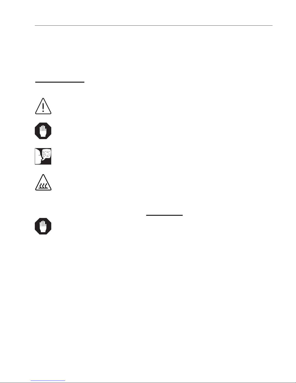
Alert Signals
Warning
Warnings alert you to a possibility of
personal injury.
Caution
Cautions alert you to a possibility of
damage to the equipment.
Note
Notes alert you to pertinent facts and
conditions.
Hot Surface
Hot surfaces alert you to a
possibility of personal injury if you
come in contact with a surface during
use or for a period of time after use.
Safety Information
Your Thermo Scientific Hot Plate has been designed with
function, reliability, and safety in mind. It is your responsibility to install it in conformance with local electrical codes.
For safe operation, please pay attention to the alert signals throughout the manual.
Warning: These products should be used only under the
operating conditions specified in the Operating Manual.
Always use safe laboratory practices and do not leave the
hotplate in operation while unattended as product funcionality or laboratory practice failures could occur that
might lead to uncontrolled or excessive heating of the top
surface. Safety procedures (including, but not limited to,
unplugging when not in use) and response plans should
be put in place to address the worst case possibility. If an
over-temperature failure occurs, the top surface temperature could rise to the maximum temperature (300-540°C
depending on your model’s specification) and remain at
that temperature indefinitely. Under these conditions, the
material being heated on the surface of the hotplate could
reach levels in excess of the maximum temperature.
Caution
Do not use metal foil, metal vessels,
or any other insulating material on top
plate. Top plate can be damaged.
Warnings
To avoid electrical shock, always:
1. Use a properly grounded electrical outlet of correct voltage and current handling capacity.
2. Disconnect from the power supply prior to maintenance and servicing.
To avoid personal injury:
1. Do not use in the presence of flammable or
combustible materials; top surface can reach the
“Flash Point Temperature” of many chemicals.
Fire or explosion may result. This device contains components which may ignite such materials. This Hot Plate is not explosion proof.
2. Refer servicing to qualified personnel.
3. “Caution: Hot Surface. Avoid Contact.” The surface of the hot plate will remain hot for some
time after use.
3
Page 4

SAFETY INFORMATION
Please note the following WARNINGS:
This warning is presented for compliance with California
Proposition 65 and other regulatory agencies and only
applies to the insulation in this product. This product
contains refractory ceramic, refractory ceramic fiber or
fiberglass insulation, which can produce respirable dust or
fibers during disassembly. Dust or fibers can cause
irritation and can aggravate preexisting respiratory
diseases. Refractory ceramic and refractory ceramic
fibers (after reaching 1000°C) contain crystalline silica,
which can cause lung damage (silicosis). The International Agency for Research on Cancer (IARC) has classified
refractory ceramic fiber and fiberglass as possibly
carcinogenic (Group 2B), and crystalline silica as
carcinogenic to humans (Group 1).
The insulating materials can be located in the door, the
hearth collar, in the chamber of the product or under the
hot plate top. Tests performed by the manufacturer
indicate that there is no risk of exposure to dust or
respirable fibers resulting from operation of this product
under normal conditions. However, there may be a risk of
exposure to respirable dust or fibers when repairing or
maintaining the insulating materials, or when otherwise
disturbing them in a manner which causes release of dust
or fibers. By using proper handling procedures and
protective equipment you can work safely with these
insulating materials and minimize any exposure. Refer to
the appropriate Material Safety Data Sheets (MSDS) for
information regarding proper handling and recommended
protective equipment. For additional MSDS copies, or
additional information concerning the handling of refractory ceramic products, please contact the Customer Service
Department at 1-800-553-0039.
4
Page 5

Introduction
Warning
Do not use in the presence of flammable or combustible materials; fire or
explosion may result. This device contains components which may ignite
such materials.
Intended Use
The Type 2200 hot plates are general purpose heating
devices intended for laboratory procedures requiring temperatures from 38°C to 371°C (700°F).
The unit consists of 1) a heated plate, and 2) an
adjustable temperature control.
Principles of Operation
The aluminum top plate is heated by two resistant heaters
embedded in a refractory material. The plate is made of
cast aluminum to aid in uniform surface temperature. The
temperature of the plate is controlled by a bimetallic thermostat. The case supports the top plate and also serves
to house the electrical connections and the bimetallic
thermostat.
5
Page 6

General Specifications
Model Numbers: HPA2230M* HPA2234M HPA2235M* HPA2235M-13 HPA2230M-26 HPA2238M
Top Plate: 12” x 12” (30 cm X 30 cm)
Overall Width: 12” (30 cm)
Dimensions: Height: 6.125” (15.6 cm); Depth: 13” (33 cm)
Weight: 17.5 lbs. (7.9 kg)
Electrical Ratings:
Control Circuit
Model No. Volts Amps Watts Phase Freq.
HPA2230M* 240 6.7 1600 1 50/60
HPA2234M 100 15 1500 1 50/60
HPA2235M* 120 13.3 1600 1 50/60
HPA2235M-13 115 13 1500 1 50/60
HPA2230M-26 240 6.7 1600 1 50/60
HPA2238M 208 7.7 1600 1 50/60
Maximum Temperatures: 371°C (700°F)
Maximum Weight on Top Plate 40 lbs. (18.1 kg)
NOTES: Supplied with three wire cord and plug.
(-13) model—CSA listed.
(-26) model—Supplied with European Cord Set.
* U.L. Listed
6
Page 7

Installation
Warning
Use a properly grounded electrical
outlet of correct voltage and current
handling capacity.
Do not use in the presence of flammable or combustible materials; fire or
explosion may result. This device contains components which may ignite
such materials.
Caution
Space unit 6 inches from combustible
materials. This permits the heat to
escape so as not to create a possible
fire hazard.
Caution
Do not place metal containers, metal
foil, or any insulating materials on
heating surface. This action may permanently damage the aluminum heating surface.
Site Selection
Install hot plate on a sturdy surface and allow space for
ventilation.
The electrical specifications are listed on the specification
plate on the side of the hot plate. Consult customer service if your electrical service is different than those listed
on the specification plate. Prior to connecting your Type
2200 hot plate to your electrical supply, be sure the dial
switch is in the OFF position.
Caution
Gross weight of items placed on top of
hot plate should not exceed 40 lbs.
(18.1 kg).
7
Page 8

Operation
Warning
Disconnect from the power supply
prior to maintenance and servicing.
Refer servicing to qualified personnel.
Hot Surface
Caution - Hot surface. Avoid Contact
Dial (Power) Switch
The power is turned ON or OFF by means of the dial
switch. The power is ON when the pointer on the dial is at
or near the FIRST MARK on the dial plate.
Dial (Control) Switch
Turn dial clockwise to set desired temperature. Dial marks
indicate approximate surface temperature in °C. The
green cycle light will illuminate at or near the FIRST
MARK on the dial plate. (If this does not occur see recalibration instructions on page 8.) When the temperature for
a given dial setting has been reached, the light will cycle
OFF and ON at a rate required to hold that temperature.
If the cycle light is OFF, hot plate may still be hot. To turn
hot plate off, turn dial switch to the fully counterclockwise
position.
8
Page 9

Preventive Maintenance
Note
Do not use emery paper to clean contact points.
Bimetal control contact points may need cleaning after
severe or extended use.
a) Disconnect hot plate from power supply.
b) Turn hot plate upside down and remove bottom
plate.
c) The contact points are accessible now and may
be cleaned with fine sandpaper or a contact file.
d) If contact points are severely pitted or burned,
replacement is suggested at this time. (Refer to
replacement of control unit.)
e) Replace bottom cover.
f) Turn hot plate upright and reconnect to power
supply.
9
Page 10

Troubleshooting
The Troubleshooting Guide is intended to aid in defining and correcting possible service problems. When
using the chart, select the problem category that resembles the malfunction. Then proceed to the possible
causes category and take necessary corrective action.
Problem Possible Cause Corrective Action
The cycle light does not Hot plate not connected to Check hot plate connections to
illuminate. power supply. power source.
Cycle light burned out. Replace cycle light.
Hot plate does not heat. No power. Check power source and fuse.
Defective electrical hookup. Repair electrical hookup.
Burned out heating element. Replace defective element.
Burned out heater coil on control Replace heater coil.
unit.
Hot plate does not hold Control out of calibration. Refer to recalibration instructions.
temperature.
10
Page 11

Maintenance and Servicing
Warning
Disconnect from the power supply
prior to maintenance and servicing.
Refer servicing to qualified personnel.
Note
Perform only maintenance described
in this manual. Contact an authorized
dealer or our factory for parts and
assistance.
Warning
Please note the following WARNINGS:
This warning is presented for compliance with California
Proposition 65 and other regulatory agencies and only
applies to the insulation in this product. This product
contains refractory ceramic, refractory ceramic fiber or
fiberglass insulation, which can produce respirable dust or
fibers during disassembly. Dust or fibers can cause
irritation and can aggravate preexisting respiratory
diseases. Refractory ceramic and refractory ceramic
fibers (after reaching 1000°C) contain crystalline silica,
which can cause lung damage (silicosis). The International Agency for Research on Cancer (IARC) has classified
refractory ceramic fiber and fiberglass as possibly
carcinogenic (Group 2B), and crystalline silica as
carcinogenic to humans (Group 1).
The insulating materials can be located in the door, the
hearth collar, in the chamber of the product or under the
hot plate top. Tests performed by the manufacturer
indicate that there is no risk of exposure to dust or
respirable fibers resulting from operation of this product
under normal conditions. However, there may be a risk of
exposure to respirable dust or fibers when repairing or
maintaining the insulating materials, or when otherwise
disturbing them in a manner which causes release of dust
or fibers. By using proper handling procedures and
protective equipment you can work safely with these
insulating materials and minimize any exposure. Refer to
the appropriate Material Safety Data Sheets (MSDS) for
information regarding proper handling and recommended
protective equipment. For additional MSDS copies, or
additional information concerning the handling of refractory ceramic products, please contact the Customer Service
Department at 1-800-553-0039.
To Replace Insulator on
Adjusting Shaft
a) Disconnect hot plate from power supply.
b) Turn hot plate upside down and remove bottom
cover.
11
Page 12

MAINTENANCE AND SERVICING
c) Loosen set screw on stop collar and screw
adjusting shaft out to remove insulator.
d) Insert new insulator and screw the shaft in part
way. (Recalibration is necessary—refer to recalibration instructions on page 10.)
e) Replace bottom cover.
f) Turn hot plate upright and reconnect to power
supply.
Note
Distance between coil and control
should be approximately 1/8” with control at maximum setting.
To Replace Heater Coil
a) Disconnect hot plate from power supply.
b) Turn hot plate upside down and remove bottom
cover.
c) Remove two nuts that hold heater coil to termi-
nals and slide heater coil off.
d) Install new heater coil and secure with two nuts.
e) Replace bottom cover.
f) Turn hot plate upright and reconnect to power
supply.
To Replace Cycle Light
a) Disconnect hot plate from power supply.
b) Turn hot plate upside down and remove bottom
cover. (Note placement and connection of wires
to cycle light.)
12
c) Disconnect two leads from cycle light.
d) Push in two clips on pilot light and remove by
pulling the cycle light out from the front.
e) Insert new cycle light through the front.
Page 13

MAINTENANCE AND SERVICING
f) Reconnect lead wires to cycle light terminals.
g) Replace bottom cover.
h) Turn hot plate upright and reconnect to power
supply.
To Replace Control Unit
a) Disconnect hot plate from power supply.
b) Turn hot plate upside down and remove bottom
cover.
c) Remove knob on adjusting shaft and loosen set
screw on stop collar.
d) Remove adjusting shaft and stop collar from
control unit.
e) Disconnect two white insulated wires from con-
trol unit. (Note placement and connection of
wires.)
f) Remove two screws from control unit and
remove control unit.
g) Install new control unit and secure with two
screws.
h) Reconnect two white insulated wires to control
unit.
i) Reinsert adjusting shaft and stop collar.
(Recalibration is necessary—refer to recalibration instructions.)
j) Replace bottom cover.
k) Turn hot plate upright and reconnect to power
supply.
13
Page 14

MAINTENANCE AND SERVICING
To Replace Heating Element
a) Disconnect hot plate from power supply.
b) Turn hot plate upside down and remove bottom
cover.
c) Disconnect the necessary wires to enable the
control section to be removed. Identity or mark
wires disconnected to insure proper placement
and connection when reinstalling.
d) Loosen stop collar screw and remove both the
stop collar and adjusting shaft.
e) Remove the case section from heating plate.
f) Remove metal cover and insulation block to
expose elements.
g) Remove defective element and insert new ele-
ment with the notched side up.
h) Bend the new element leads at a 90° angle and
slide them through the insulation block.
i) Slide metal cover over element leads and insu-
lation block.
j) Secure metal cover and replace case section
over heating plate.
k) Secure case section.
I) Reconnect wires disconnected in Step C.
m) Reinsert adjusting shaft and stop collar.
(Recalibration is necessary—refer to recalibration instructions.)
n) Replace bottom cover.
14
o) Turn hot plate upright and reconnect to power
supply.
Page 15

MAINTENANCE AND SERVICING
Note
Recalibration my be needed for the
control unit due to contact wear, or
because of other repairs to the hot
plate.
Note
The gap between the contact spring
and spring action limiting screw controls the difference between the “ON”
and “OFF” temperatures of the surface
plate when the control is holding a set
temperature. A narrow gap will give a
narrow control band, while a wide gap
will increase the range between the
“ON” and “OFF” temperatures. There
must be a definite “SNAP” opening
and closing of the contact points when
the control shaft is slowly screwed in
and out. This snap action, in conjunction with magnetic blow out of any arc
which tends to form between the contacts, results in long contact life.
Recalibration
a) Disconnect hot plate from power supply.
b) Turn hot plate upside down and remove bottom
plate.
c) Remove the knob from the adjusting shaft by
removing screw from knob.
d) Turn the adjusting shaft into the control mount-
ing bracket until the contact points just close
with a “snap” action.
e) Measure the gap between the contact spring
and spring action limiting screw with a feeler
gauge.
f) This gap should be between .006 and .010 for
normal operation of control.
g) Adjust the spring action limiting screw until the
proper gap is attained just before the magnetic
attraction is overcome and the points open.
h) Turn the adjusting shaft until the contact points
close and slide knob over shaft with the FIRST
MARK aligned with the pointer line. (Leave 3/16”
of space between knob and dial plate.)
i) Tighten screw on knob and check to see that
the contacts “SNAP” closed as the pointer
crosses the index line.
j) Turn knob counterclockwise until the “OFF”
mark on dial plate aligns with pointer line, and
readjust stop collar against the stop pin at this
point.
k) Tighten set screw on stop collar and check for
free rotation of the control shaft between stops.
I) Replace bottom plate.
m) Turn hot plate upright and reconnect to power
supply.
15
Page 16

Replacement Parts List
Product Name: Hot Plate (12 x 12)
Model Nos: HPA2235M-13, HPA2235M, HPA2230M, HPA2234M, HPA2230M-26, HPA2238M
Series No: 237
Key
No. Part No. Description
1 PT54X1 Plate Top Casting
2 EL20X1 Element (2 required) 120V & 240V
2 EL237X1 Element (2 required) 100V
2 EL20X2 Element (2 required) 208V
3 JC237X1 Insulation, Castable
4 CN137X1 Control
5 JSX8 Insulator
6 SF54X1 Shaft
7 CR178X1 Cord Set for HPA2235M, HPA2235M-13, HPA2234M
7 CR64X2A Cord Set for HPA2230M-26
7 CR64X1A Cord Set for HPA2230M, 240V, HPA2238M, 208V
8 KBX18 Knob
9 TRX11 Terminal Block
10 PLX35 Pilot Light
11 HT54X2 Heater Coil for HPA2235M, 120V, UL, HPA2234M, 100V, HPA2235M-13,120V, CSA
11 HT54X1 Heater Coil for HPA2230M, HPA2230M-26, HPA2238M
16
Page 17

Exploded View
17
Page 18

Wiring Diagram
18
Page 19

Ordering Procedures
Please refer to the Specification Plate for the complete
model number, serial number, and series number when
requesting service, replacement parts or in any correspondence concerning this unit.
All parts listed herein may be ordered from the Thermo
Scientific dealer from whom you purchased this unit or
can be obtained promptly from the factory. When service
or replacement parts are needed we ask that you check
first with your dealer. If the dealer cannot handle your
request, then contact our Customer Service Department
at 563-556-2241 or 800-553-0039.
Prior to returning any materials, please contact our
Customer Service Department for a “Return Materials
Authorization” number (RMA). Material returned without
an RMA number will be refused.
19
Page 20

Two Year Limited Warranty
This Thermo Scientific product is warranted to be free of defects in materials and workmanship for two (2)
years from the first to occur of (i) the date the product is sold by the manufacturer or (ii) the date the product is
purchased by the original retail customer (the “Commencement Date”). Except as expressly stated above, the
MANUFACTURER MAKES NO OTHER WARRANTY, EXPRESSED OR IMPLIED, WITH RESPECT TO THE
PRODUCTS AND EXPRESSLY DISCLAIMS ANY AND ALL WARRANTIES, INCLUDING BUT NOT LIMITED
TO, WARRANTIES OF DESIGN, MERCHANT ABILITY AND FITNESS FOR A PARTICULAR PURPOSE.
An authorized representative of the manufacturer must perform all warranty inspections. In the event of a
defect covered by the warranty, we shall, as our sole obligation and exclusive remedy, provide free replacement parts to remedy the defective product. In addition, for products sold within the continental United States
or Canada, the manufacturer shall provide free labor to repair the products with the replacement parts, but
only for a period of ninety (90) days from the Commencement Date.
The warranty provided hereunder shall be null and void and without further force or effect if there is any (i)
repair made to the product by a party other than the manufacturer or its duly authorized service representative, (ii) misuse (including use inconsistent with written operating instructions for the product), mishandling,
contamination, overheating, modification or alteration of the product by any customer or third party or (iii) use
of replacement parts that are obtained from a party who is not an authorized dealer of Thermo Scientific products.
Heating elements, because of their susceptibility to overheating and contamination, must be returned to the
factory and if, upon inspection, it is concluded that failure is due to factors other than excessive high temperature or contamination, the manufacturer will provide warranty replacement. As a condition to the return of any
product, or any constituent part thereof, to the factory, it shall be sent prepaid and a prior written authorization
from the manufacturer assigning a Return Materials Number to the product or part shall be obtained.
IN NO EVENT SHALL THE MANUFACTURER BE LIABLE TO ANY PARTY FOR ANY DIRECT, INDIRECT,
SPECIAL, INCIDENTAL, OR CONSEQUENTIAL DAMAGES, OR FOR ANY DAMAGES RESULTING FROM
LOSS OF USE OR PROFITS, ANTICIPATED OR OTHERWISE, ARISING OUT OF OR IN CONNECTION
WITH THE SALE, USE OR PERFORMANCE OF ANY PRODUCTS, WHETHER SUCH CLAIM IS BASED ON
CONTRACT, TORT (INCLUDING NEGLIGENCE), ANY THEORY OF STRICT LIABILITY OR REGULATORY
ACTION.
For the name of the authorized Thermo Scientific product dealer nearest you or any additional information, contact us:
2555 Kerper Blvd., Dubuque, Iowa, 52004-0797
Phone: 563-556-2241 or 1-800-553-0039
Fax: 563-589-0516
Web: www.thermo.com
20
 Loading...