

Therma-Tek TC24-24RBS Operators Manual
OWNERS MANUAL AND INSTALLATION INSTRUCTIONS
U
C US
LI STED
Made in U.S.A
L
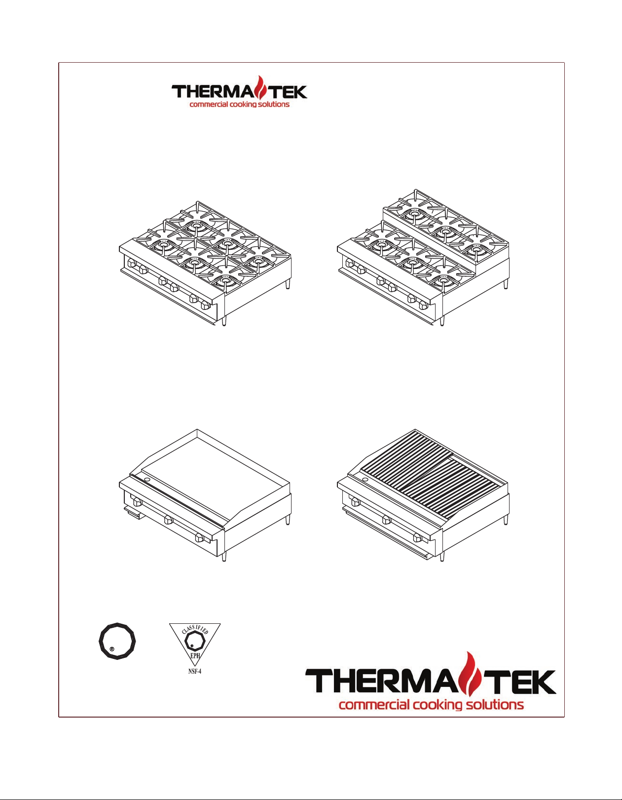
MODEL # TC36-6 (shown)
MODEL # TC36G (shown)
U
L
COUNTER SERIES
MODEL # TCHP36SU-6 (shown)
MODEL # TC36RB (shown)
INTRODUCTION/ SAFETY PRECAUTIONS
This equipment is for commercial use by trained professionals familiar with commercial cooking
FOR YOUR SAFETY
FOR YOUR SAFETY
supplier.
:
THIS EQUIPMENT.
CALIFORNIA PROPOSITON 65 – WARNING
Thank you for choosing your new THERMA-TEK Equipment. Our Products are designed to be safe and
reliable when properly cared for and used reasonably. Your service agency or dealer recommends periodic
inspections. Installation, maintenance, and repairs should be performed by your local authorized service
agency. This equipment is not intended for home use.
equipment. It is the responsibility of the Supervisor or equivalent person to ensure that users wear
suitable protective clothing and safety gear. Caution: some parts of the equipment become very hot and
will cause burns if accidentally touched.
DO NOT STORE OR USE GASOLINE OR OTHER FLAMMABLE VAPORS OR LIQUIDS IN THE
VICINITY OF THIS OR ANY OTHER APPLIANCE.
If you smell gas:
1. Shut off gas to appliance.
2. Extinguish any open flame.
3. If odor continues, immediately call your gas
Consult your local gas supplier for instructions to be followed in the event you smell gas.
Post these instructions in a prominent location.
WARNING
MAINTENANCE CAN CAUSE PROPERTY DAMAGE, INJURY OR DEATH. READ THE
OWNERS/INSTALLERS MANUAL THOROUGHLY BEFORE INSTALLING OR SERVICING
The burning of gas cooking fuel generates some by- products which are on the list of substances known by the State of
California to cause cancer or reproductive harm. California law requires businesses to warn customers of potential exposure to
such substances. To minimize exposure to these substances, always operate this unit according to the owners/installation
manual, ensuring you provide good ventilation when cooking with gas.
IMPROPER INSTALLATION, ADJUSTMENT ALTERATION, SERVICE OR
PLEASE RETAIN THESE INSTRUCTIONS FOR FUTURE REFERENCE
1

INSTALLATION AND SAFETY GUIDELINES
IMPORTANT
Safe and satisfactory operation of your equipment depends on its proper installation. Installation must
conform to local codes, or in the absence of local codes with the National Fuel Code ANSI Z223.1 (latest
edition).
All THERMA-TEK appliances are shipped with a gas pressure regulator packed with the unit. All units are
adjusted, tested, and inspected at the factory prior to shipment.
After uncrating, immediately check the equipment for visible signs of shipping damage. If such damage has
occurred, do not refuse shipment, but contact the shipper and file appropriate freight claims.
GENERAL
• Installation of this equipment should be made by licensed and authorized personnel.
• A manual gas shut-off valve must be installed in the gas supply (service) line ahead of the appliance
and gas pressure regulator installed in the gas stream for safety and ease of future service.
• The gas pressure regulator supplied must be installed on the appliance prior to connecting the
equipment to the gas line. Failure to install a regulator will void the equipment warranty and result in
a potentially hazardous condition.
• The appliance and its individual shut off valve must be disconnected from the gas supply system
during any pressure testing of that system in excess of ½ PSI.
• The appliance must be isolated from the gas supply system by closing its individual shut off valve
during any pressure testing of the gas supply piping system at test pressure equal to or less than ½ PSI.
• Please contact the factory, the factory representative, or a local authorized service company to perform
maintenance and repairs.
RATING PLATE
Information on this plate includes the model and serial number. When communicating with the factory about
a unit or requesting special parts or information, this information is required for proper identification. Other
information on the plate is the BTU/hr input of the burners, gas pressure in inches WC, and whether the unit
has orifices for natural or propane gas.
IMPORTANT: The appliance must be connected only to the type of gas identified on the rating plate.
GAS CONVERSION
We recommend that the appliance be ordered from the factory for the type of gas at the installation site.
When gas conversion is necessary contact the factory for a proper gas conversion kit.
2

INSTALLATION AND SAFETY GUIDELINES
CLEARANCES
• The unit must be kept clear of all combustibles.
• The unit must be installed with the 4” legs supplied for proper operation.
• Minimum clearance from combustible construction:
Side Back
o Open top 12” 12”
o Griddle 6” 12”
• Minimum clearance from non-combustible:
Side Back
• Open top 0” 0”
• Broiler 0” 0” (For use in noncombustible locations only)
• Griddle 0” 6”
LEVELING
A carpenter’s spirit level should be placed on the cooking surface and the unit leveled side-to-side, and front
to back. If it is not level, burner combustion may be erratic or the unit may not function efficiently.
AIR SUPPLY AND VENTILATION
The area around the appliance must be kept clear to avoid any obstructions of the flow of combustion and
ventilation air as well as for ease of maintenance, service, and proper appliance operation. Keep clearance for
openings into the combustion chamber and adequate air supply. Means must be provided for any commercial,
heavy duty-cooking appliance to exhaust combustion wastes to the outside of the building.
Air movement should be checked during installation. Strong exhaust fans in the hood or in the overall air
conditioning system can produce a slight draft in the room, which can interfere with pilot or burner
performance. If pilot or burner problems persist, make up air openings or baffles may have to be provided in
the room.
Filters and drip troughs should be part of any industrial hood, but consult local codes before constructing and
installing any hood. The duct system, exhaust hood, and filter bank must be cleaned on a regular basis and
kept free of grease.
ALTITUDE
The appliance input rating (BTU/hr) is for elevations up to 2000 feet. For elevations above 2000 feet, the rate
should be reduced 4% for each 1000 feet above sea level. The correct orifices are installed at the factory if
the operating altitude is known at the time of sale.
3

INSTALLATION AND SAFETY GUIDELINES
GAS CONNECTION
The gas supply (service) line must be at least the same size or larger than the inlet line of the appliance.
CHEFTECH counter equipment is supplied with a ¾” NPT Schedule 40 inlet. Sealant on all pipe joints must
be resistive to LP gas.
MANUAL SHUT-OFF VALVE
A manual shut-off valve must be installed in the gas service line ahead of the appliance and regulator in the
gas stream and in a position where it can be reached quickly in the event of an emergency. The manual shutoff valve is supplied by the installer.
PRESSURE REGULATOR
All commercial cooking equipment must have a pressure regulator on the incoming service line for safe and
efficient operation, since pressure may fluctuate on local demand. A regulator is supplied with the appliance.
Failure to install a pressure regulator will void the equipment warranty. The regulators are adjusted at
the factory, 5.0” WC for natural gas, and 10.0” WC for propane gas. Ensure the supply pressure is within the
following range: Natural Gas 6.0” WC to 13.0” WC / Propane Gas 11.0”WC to 13.0” WC.
Any adjustments to the regulators must be made only by qualified service personnel with proper test
equipment.
RIGID CONNECTIONS
Double check any installer supplied gas pipes visually and blow them out with compressed air to clear any
dirt particles, threading chips, or any other foreign matter before installing a service line. Those particles will
clog orifices when gas pressure is applied. All connections must be sealed with a joint compound for LP gas
and tested with a soapy water solution before lighting any pilots.
FLEXIBLE COUPLINGS, CONNECTORS AND CASTERS
If the unit is to be installed with flexible coupling and or quick disconnect fittings, the installer must use a
heavy duty commercial flexible connector at least ¾” NPT (with suitable strain relief) in compliance with the
standard for connectors for movable gas appliances, ANSI Z21.69-1987 and Addenda Z2.169a-1989 (or latest
edition) or connectors for movable appliances, CAN/CGA-6.16 (or latest edition) and quick disconnect device
must comply with the standard for quick disconnect devices for use with gas fuel,
ANSI Z21.41-1989 (or latest edition) or quick disconnect devices for use with gas fuel, CAN1-69 (or latest
edition). Adequate means must be provided to limit the movement of the appliance. Domestic connectors are
not suitable.
When the appliance is supplied with casters and is connected to the supply piping by means of a connector for
movable appliances, and if disconnecting the restraint is necessary, this restraint must be reconnected after the
appliance is returned to its original installation position. The strain relief is a cable attached to the rear of the
appliance.
4
 Loading...