

Page 1
Mega-Arc®Constant Current
Welding Machine
For the Following Specs:
6031A-3 300 Amp MA-3
•
6032A-3 300 Amp MA-3
•
6036A-3 400 Amp MA-4
•
6036B-3 400 Amp MA-4
•
6037A-3 400 Amp MA-4
•
6041A-4 500 Amp MA-5
•
6042A-3 500 Amp MA-5
•
6046A-3 750 Amp MA-7
•
6047A-3 750 Amp MA-7
•
OWNER’S MANUAL Number 430429-238 (Rev - B)
Revised September 30, 1998
IMPORTANT: Readtheseinstructionsbeforeinstalling,operating, or servicing this system.
THERMAL ARC INC., TROY, OHIO 45373-1085, U.S.A.
Page 2

Page 3

430429-238
Table of Contents
INTRODUCTION 1
How To Use This Manual ..................................1-1
Equipment Identification ..................................1-1
Receipt Of Equipment ...................................1-1
SAFETY INSTRUCTIONS AND WARNINGS 2
DESCRIPTION OF EQUIPMENT 3
General ...........................................3-1
Controls And Connections .................................3-1
Welding Current Ranges ..................................3-1
INSTALLATION 4
Location ...........................................4-1
Internal Wiring Check ....................................4-1
Connecting Welding Machine To Line Voltage .......................4-1
Grounding ..........................................4-1
Welding Leads .......................................4-2
OPERATION 5
Sequence Of Operation ...................................5-1
High Frequency Considerations ..............................5-1
MAINTENANCE 6
Lubrication .........................................6-1
Inspection And Cleaning ..................................6-1
TROUBLESHOOTING 7
PARTS LIST 8
Equipment Identification ..................................8-1
How To Use This Parts List .................................8-1
DIAGRAMS
December 1, 1997 Revised
Page 4

INTRODUCTION
430429-238
INTRODUCTION
How To Use This Manual
This Owner’s Manual usually applies to just the
underlined specification or part numbers listed on
the cover. If none are underlined, they are all covered by this manual.
Throughout this manual, the words WARNING,
CAUTION, and NOTE may appear. Pay particular
attention to the information provided under these
headings. These special annotationsareeasilyrecognized as follows:
WARNING gives information regarding possible personal injury. Warnings will be enclosed
in a box such as this.
CAUTION refers to possible equipment
damage. Cautions will be shown in bold
type.
NOTE offers helpful information concerningcertainoperatingprocedures. Notes will
be shown in italics.
Equipment Identification
The unit’s identification number (specification or
part number), model, and serial number usually
appear on a nameplate attached to the control
panel. In some cases, the nameplate may be attached to the rear panel. Equipment which does not
have a controlpanel such asgun and cableassemblies are identified only by the specification or part
number printed on the shipping container. Record
these numbers for future reference.
Receipt Of Equipment
When you receivethe equipment, checkit against
the invoice to make sure it is complete and inspect
theequipmentforpossibledamageduetoshipping.
If there is any damage, notify the carrier immediately to file a claim. Furnish complete information
concerning damage claims or shipping errors to
Thermal Arc, Order Department, 2200 Corporate
Drive, Troy, Ohio 45373-1085. Include all equipment identification numbers as described above
along with a full description of the parts in error.
Move the equipment to the installation site before
uncrating the unit. A lifting eye extends through the
top of the cabinet on most equipment to facilitate
handling with a hoist or crane. Use care to avoid
damaging the equipment when using bars, hammers, etc., to uncrate the unit.
WARNING: Falling machine due
to lifting eye failure may cause
death or serious injury.
• Lifting device may fail when overloaded.
• This lifting device is designed to lift the
power source ONLY. If the machine is
equipped with a trailer or accessories over
100 pounds, DO NOT LIFT by lifting eyes.
• Avoid sudden jerks, drops, or swinging.
• Check lifting device components visually
for looseness and signs of metal fatigue.
• Before changing any hardware, check
grade and size of bolts, and replace with
bolts of equal or higher size and grade.
Additional copies of this manual may be purchased by contacting Thermal Arc at the address
given above. Include the Owner’s Manual number
and equipment identification numbers.
December 1, 1997 Revised 1-1
Page 5
ARC WELDING SAFETY INSTRUCTIONS AND WARNINGS
Instruction 830001
ARC WELDING SAFETY INSTRUCTIONS AND WARNINGS
ARC WELDING can be hazardous.
PROTECT YOURSELF AND OTHERS FROM POSSIBLE SERIOUS INJURY OR DEATH. KEEP CHILDREN AWAY. PACEMAKER
WEARERSKEEPAWAYUNTIL CONSULTING YOURDOCTOR. DONOT LOSETHESE INSTRUCTIONS.READ OPERATING/INSTRUCTION MANUAL BEFORE INSTALLING, OPERATING OR SERVICING THIS EQUIPMENT.
Welding products and welding processes can cause serious injury or death, or damage to other equipment or property, if the operator does
not strictly observe all safety rules and take precautionary actions.
Safe practices have developed from past experience in the use of welding and cutting. These practices must be learned through study and
trainingbefore using this equipment. Anyonenot having extensive training inwelding and cutting practicesshould not attempt to weld. Certain
of the practices apply to equipment connected to power lines; other practices apply to engine driven equipment.
Safe practices are outlined in the American National Standard Z49.1 entitled:
other guides to what you should learn before operating this equipment are listed at the end of these safety precautions.
HAVE ALL INSTALLATION, OPERATION, MAINTENANCE, AND REPAIR WORK PERFORMED ONLY BY QUALIFIED PEOPLE.
ELECTRIC SHOCK can kill.
Touchingliveelectrical partscan cause fatal shocks
or severe burns. The electrode and work circuit is
electricallylive whenever the output is on. The input
power circuit and machine internal circuits are also
livewhenpower ison.In semiautomaticorautomatic
wire welding, the wire, wire reel, drive roll housing,
and all metal parts touching the welding wire are
electrically live. Incorrectly installed or improperly
grounded equipment is a hazard.
1. Do not touch live electrical parts.
2. Wear dry, hole-free insulating gloves and body protection.
3. Insulate yourselffrom work and ground usingdry insulating mats
or covers.
4. Disconnect input power or stop engine before installing or servicing this equipment. Lock input power disconnect switch open,
or remove line fuses so power cannotbe turned on accidentally.
5. Properly install and ground this equipment according to its
Owner’s Manual and national, state, and local codes.
SAFETY IN WELDING AND CUTTING. This publication and
6. Turn off all equipment when not in use. Disconnect power to
equipment if it will be left unattended or out of service.
7. Use fully insulated electrode holders. Never dip holder in water
to cool it or lay it down on the ground or the work surface.Donot
touch holders connected to two welding machines at the same
time or touch other people with the holder or electrode.
8. Do notuse worn,damaged, undersized, orpoorly splicedcables.
9. Do not wrap cables around your body.
10. Ground the workpiece to a good electrical (earth) ground.
11. Do not touch electrode while in contact with the work (ground)
circuit.
12. Useonly well-maintainedequipment. Repairor replacedamaged
parts at once.
13. In confined spaces or damp locations, do not use a welder with
AC output unless it is equipped with a voltage reducer. Use
equipment with DC output.
14. Wear a safety harness to prevent falling if working above floor
level.
15. Keep all panels and covers securely in place.
ARC RAYS can burn eyes and skin;
NOISE can damage hearing.
Arc rays from the welding process produce intense
heat and strong ultraviolet rays that can burn eyes
and skin. Noise from some processes can damage
hearing.
Eye protection filter shade selector for welding or cutting (goggles or helmet), from AWS A6.2-73.
Welding or Cutting
Operation
Torch soldering
Torch brazing
Oxygen cutting
Light
Medium
Heavy
Gas welding
Light
Medium
Heavy
Shielded metal-arc welding
(stick) electrodes
Electrode Size
Metal Thickness
or Welding Current
—
—
Under 1 in., 25 mm
1 to 6 in., 25-150 mm
Over 6 in., 150 mm
Under 1/8 in., 3 mm
1/8 to 1/2 in., 3-12 mm
Over 1/2 in., 12 mm
Under 5/32 in., 4 mm
5/32 to 1/4 in., 4 to 6.4 mm
Over 1/4 in., 6.4 mm
Filter
Shade
No.
2
3or4
3or4
4or5
5or6
4or5
5or6
6or8
10
12
14
1. Wear a welding helmet fitted with a proper shade of filter (see
ANSI Z49.1 listed in Safety Standards) to protect your face and
eyes when welding or watching.
2. Wear approved safety glasses. Side shields recommended.
3. Use protective screens or barriers to protect others from flash
and glare; warn others not to watch the arc.
4. Wear protective clothing made from durable, flame-resistant
material (wool and leather) and foot protection.
5. Use approved ear plugs or ear muffs if noise level is high.
Welding or Cutting
Operation
Gas metal-arc welding (MIG)
Non-ferrous base metal
Ferrous base metal
Gastungstenarc welding (TIG)
Atomic hydrogen welding
Carbon arc welding
Plasma arc welding
Carbon arc air gouging
Light
Heavy
Plasma arc cutting
Light
Medium
Heavy
Electrode Size
Metal Thickness
or Welding Current
All
All
All
All
All
All
Under 300 Amp
300 to 400 Amp
Over 400 Amp
May 8, 1996 2-1
Filter
Shade
No.
11
12
12
12
12
12
12
14
9
12
14
Page 6
ARC WELDING SAFETY INSTRUCTIONS AND WARNINGS
Instruction 830001
FUMES AND GASES can be hazardous
to your health.
Weldingproduces fumesandgases. Breathingthese
fumes and gases can be hazardous to your health.
1. Keep your head out of the fumes. Do not breath the fumes.
2. If inside, ventilate the area and/or use exhaust at the arc to
remove welding fumes and gases.
3. If ventilation is poor, use an approved air-supplied respirator.
WELDING can cause fire or explosion.
Sparks and spatter fly off from the welding arc. The
flying sparks and hot metal, weld spatter, hot workpiece, and hot equipment cancause fires and burns.
Accidental contact of electrode or welding wire to
metal objects can cause sparks, overheating, or fire.
1. Protect yourself and others from flying sparks and hot metal.
2. Do not weld where flying sparks can strike flammable material.
3. Remove all flammables within 35 ft (10.7 m) of the welding arc.
If this is not possible, tightly cover them with approved covers.
4. Be alert that welding sparks and hot materials from welding can
easily go through small cracks and openings to adjacent areas.
4. Read the Material Safety Data Sheets (MSDSs) and the manufacturer’s instruction for metals, consumables, coatings, and
cleaners.
5. Work in a confined space only if it is well ventilated, or while
wearing an air-supplied respirator. Shielding gases used for
welding can displace air causing injury or death. Be sure the
breathing air is safe.
6. Do not weld in locations near degreasing, cleaning, or spraying
operations. The heat and raysof the arc can react with vapors to
form highly toxic and irritating gases.
7. Do not weld on coated metals, such as galvanized, lead, or
cadmium plated steel, unless the coating is removed from the
weld area, the area is well ventilated, and if necessary, while
wearing an air-supplied respirator. The coatings and any metals
containing these elements can give off toxic fumes if welded.
5. Watch for fire, and keep a fire extinguisher nearby.
6. Be aware that welding on a ceiling, floor, bulkhead, or partition
can cause fire on the hidden side.
7. Do not weld on closed containers such as tanks or drums.
8. Connect work cable to the work as close to the welding area as
practical to prevent welding current from traveling long, possibly
unknown paths and causing electric shock and fire hazards.
9. Do not use welder to thaw frozen pipes.
10. Remove stick electrode from holder or cut off welding wire at
contact tip when not in use.
11. Wear oil-free protective garments such as leather gloves, heavy
shirt, cuffless trousers, high shoes, and a cap.
FLYING SPARKS AND HOT METAL can
cause injury.
Chipping and grinding cause flying metal. As welds
cool, they can throw off slag.
CYLINDERS can explode if damaged.
Shielding gas cylinderscontain gas under high pressure. If damaged, a cylinder can explode. Since gas
cylinders are normally part of the welding process,
be sure to treat them carefully.
1. Protectcompressedgas cylindersfromexcessiveheat, mechanical shocks, and arcs.
2. Install and secure cylinders in an upright position by chaining
themto astationarysupport orequipment cylinderracktoprevent
falling or tipping.
ENGINE EXHAUST GASES can kill.
Engines produce harmful exhaust gases.
1. Wear approved face shield or safety goggles. Side shields recommended.
2. Wear proper body protection to protect skin.
3. Keep cylindersaway from any weldingor other electricalcircuits.
4. Never allow a welding electrode to touch any cylinder.
5. Use only correct shielding gas cylinders, regulators, hoses, and
fittings designed for the specific application; maintain them and
associated parts in good condition.
6. Turn face away from valve outlet when opening cylinder valve.
7. Keep protective cap in place over valve except when cylinder is
in use or connected for use.
8. Read and follow instructionson compressed gas cylinders, associated equipment, and CGA publication P-1 listed in Safety
Standards.
ENGINES can be hazardous.
1. Use equipment outside in open, well-ventilated areas.
2. If used in a closed area, vent engine exhaust outside and away
from any building air intakes.
2-2 May 8, 1996
Page 7
ARC WELDING SAFETY INSTRUCTIONS AND WARNINGS
Instruction 830001
ENGINE FUEL can cause fire or
explosion.
Engine fuel is highly flammable.
1. Stop engine before checking or adding fuel.
MOVING PARTS can cause injury.
Moving parts,such as fans, rotors, and beltscan cut
fingers and hands and catch loose clothing.
1. Keep all doors, panels, covers, and guards closed and securely
in place.
2. Stop engine before installing or connecting unit.
SPARKS can cause BATTERY GASES
TO EXPLODE; BATTERY ACID can
burn eyes and skin.
Batteriescontainacid andgenerate explosivegases.
STEAM AND PRESSURIZED HOT
COOLANT can burn face, eyes, and
skin.
The coolantin the radiatorcan be very hot andunder
pressure.
WARNING: This product, when used for welding or cutting, produces fumes or gases which contain chemicals known to the State
of California to cause birth defects and, in some cases, cancer. (California Health & Safety Code Sec. 25249.5 et seq.)
NOTE: Considerations About Welding And The Effects Of Low Frequency Electric And Magnetic Fields
The following is a quotation from the General Conclusions Section of the U.S. Congress, Office of TechnologyAssessment,
of Power Frequency Electric& Magnetic Fields — Background Paper, OTA-BP-E-63 (Washington, DC: U.S. Government Printing Office, May
1989): “... there is now a very large volume of scientific findings based on experiments at the cellular level and from studies with animals and
people which clearly establish that low frequency magnetic fields can interact with, and produce changes in, biological systems. While most of
this work is of very high quality, the results are complex. Current scientific understanding does not yet allow us to interpret the evidence in a
single coherent framework. Even more frustrating, it does not yet allow us to draw definite conclusions about questions of possible risk or to
offer clear science-based advice on strategies to minimize or avoid potential risks.”
To reduce magnetic fields in the workplace, use the following procedures:
1. Keep cables close together by twisting or taping them.
2. Arrange cables to one side and away from the operator.
2. Donot add fuelwhile smokingor ifunit isnear anysparksoropen
flames.
3. Allow engine to cool before fueling. If possible, check and add
fuel to cold engine before beginning job.
4. Do not overfill tank — allow room for fuel to expand.
5. Do not spill fuel. If fuel is spilled,clean up before starting engine.
3. Have only qualified people remove guards or covers for maintenance and troubleshooting as necessary.
4. Toprevent accidental startingduring servicing,disconnectnegative (-) battery cable from battery.
5. Keep hands, hair, loose clothing, and tools away from moving
parts.
6. Reinstall panels or guards and close doors when servicing is
finished and before starting engine.
1. Always wear a face shield when working on a battery.
2. Stop engine before disconnecting or connecting battery cables.
3. Do not allow tools to cause sparks when working on a battery.
4. Do not use welder to charge batteries or jump start vehicles.
5. Observe correct polarity (+ and –) on batteries.
1. Do not remove radiator cap when engine is hot. Allow engine to
cool.
2. Wear gloves and put a rag over cap area when removing cap.
3. Allow pressure to escape before completely removing cap.
Biological Effects
3. Do not coil or drape cables around the body.
4. Keep welding power source and cables as far awayfrom body as
practical.
About Pacemakers:
The above procedures are among those also normally recommended for pacemaker wearers. Consult your doctor for complete information.
PRINCIPAL SAFETY STANDARDS
Safety inWeldingand Cutting, ANSI Standard Z49.1, from American
Welding Society, 550 N.W. LeJeune Rd., Miami, FL 33126.
SafetyandHealth Standards, OSHA29 CFR 1910, from Superintendent of Documents, U.S. Government Printing Office, Washington,
D.C. 20402.
Recommended Safe Practices for the Preparation for Welding and
Cuttingof ContainersThatHave HeldHazardousSubstances, American Welding Society Standard AWS F4.1, from American Welding
Society, 550 N.W. LeJeune Rd., Miami, FL 33126.
National Electrical Code, NFPA Standard 70, from National Fire
Protection Association, Batterymarch Park, Quincy, MA 02269.
Safe Handling of Compressed Gases in Cylinders, CGA Pamphlet
P-1, from Compressed Gas Association, 1235 Jefferson DavisHighway, Suite 501, Arlington, VA 22202.
Code forSafety in WeldingandCutting, CSA StandardW117.2, from
Canadian Standards Association, Standards Sales, 178 Rexdale
Boulevard, Rexdale, Ontario, Canada M9W 1R3.
Safe Practices for Occupation and Educational Eye and Face Protection, ANSI Standard Z87.1, from American National Standards
Institute, 1430 Broadway, New York, NY 10018.
Cutting and Welding Processes, NFPA Standard 51B, from National
Fire Protection Association, Batterymarch Park, Quincy, MA 02269.
May 8, 1996 2-3
Page 8

ARC WELDING SAFETY INSTRUCTIONS AND WARNINGS
Instruction 830001
This page intentionally left blank.
2-4 May 8, 1996
Page 9
PRECAUTIONS DE SECURITE EN SOUDAGE A L'ARC
Instruction 830002
PRECAUTIONS DE SECURITE EN SOUDAGE A L′ARC
LE SOUDAGE A L′ARC EST DANGEREUX
PROTEGEZ-VOUS,AINSI QUELES AUTRES, CONTRE LES BLESSURES GRAVES POSSIBLES OU LA MORT. NE LAISSEZ PAS LES
ENFANTSS’APPROCHER, NI LES PORTEURSDESTIMULATEUR CARDIAQUE(A MOINSQU’ILS N’AIENT CONSULTEUN MEDECIN).
CONSERVEZ CES INSTRUCTIONS.LISEZ LE MANUEL D’OPERATION OU LES INSTRUCTIONS AVANT D’INSTALLER, UTILISER OU
ENTRETENIR CET EQUIPEMENT.
Les produits et procédés de soudage peuvent sauser des blessures graves ou la mort, de même que des dommages au reste du matériel
et à la propriété,sil’utilisateur n’adhère pas strictement à toutes les règles de sécurité et ne prend pas les précautions nécessaires.
En soudage et coupage, des pratiques sécuritaires se sont développées suite à l’expériencepassée. Ces pratiques doivent être apprises
parétude ou entraînement avant d’utiliserl’equipement. Toute personne n’ayantpas suiviun entraînementintensif en soudage et coupage
ne devrait pas tenter de souder. Certaines pratiques concernent les équipements raccordés aux lignes d’alimentation alors que d’autres
s’adressent aux groupes électrogènes.
La norme Z49.1 de l’American National Standard, intitulée “SAFETY IN WELDING AND CUTTING” présente les pratiques sécuritaires à
suivre. Ce document ainsi que d’autres guides que vous devriez connaître avant d’utiliser cet équipement sont présentés à la fin de ces
instructions de sécurité.
SEULES DES PERSONNES QUALIFIEES DOIVENT FAIRE DES TRAVAUX D’INSTALLATION, DE REPARATION, D’ENTRETIEN ET
D’ESSAI.
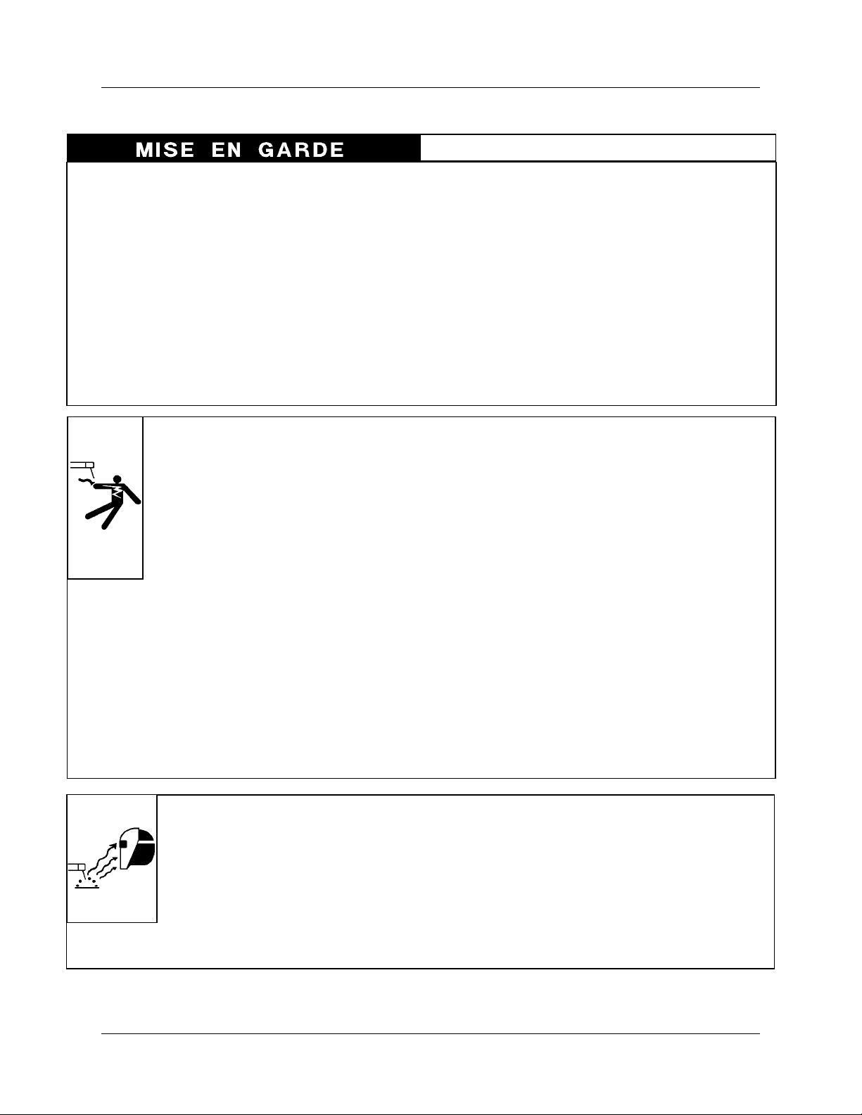
L’ELECTROCUTION PEUT ETRE
MORTELLE.
Une décharge électrique peut tuer ou brûler gravement. L’électrode et le circuit de soudage sont sous
tension dès la mise en circuit. Le circuit d’alimentation et les circuits internes de l’équipement sont
aussi sous tension dès la mise en marche. En
soudage automatique ou semi-automatique avec
fil, ce dernier, le rouleau ou la bobine de fil, le
logement des galets d’entrainement et toutes les
pièces métalliques en contact avec le fil de soudage
sont sous tension. Un équipement inadéquatement
installé ou inadéquatement mis à la terre est dangereux.
1. Ne touchez pas à des pièces sous tension.
2. Portez des gants et des vêtements isolants, secs et non troués.
3. Isolez-vousde lapièce à souderet de lamise àla terreau moyen
de tapis isolants ou autres.
4. Déconnectez la prise d’alimentation de l’équipement ou arrêtez
le moteur avant de l’installer ou d’en faire l’entretien. Bloquez le
commutateuren circuitouvert ouenlevez lesfusibles del’alimentation afin d’éviter une mise en marche accidentelle.
5. Veuillez à installer cet équipement et à le mettre à la terre selon
le manuel d’utilisation et les codes nationaux, provinciaux et
locaux applicables.
LE RAYONNEMENT DE L′ARC PEUT
BRÛLER LES YEUX ET LA PEAU; LE
BRUIT PEUT ENDOMMAGER L′OUIE.
L’arc de soudage produit une chaleur et des
rayons ultraviolets intenses, susceptibles de
brûler les yeux et la peau. Le bruit causé par
certains procédés peut endommager l’ouïe.
1. Portez une casque de soudeur avec filtre oculaire de nuance
appropriée (consultez la norme ANSI Z49 indiquéeci-après)
6. Arrêtez tout équipement après usage. Coupez l’alimentation de
l’équipement s’il est hors d’usage ou inutilisé.
7. N’utilisezquedes porte-électrodesbienisolés.Ne jamaisplonger
les porte-électrodes dans l’eau pour les refroidir. Ne jamais les
laisser traîner par terre ou sur les pièces à souder. Ne touchez
pas aux porte-électrodes raccordés à deux sources de courant
en même temps. Ne jamais toucher quelqu’un d’autre avec
l’électrode ou le porte-électrode.
8. N’utilisez pas de câbles électriques usés, endommagés, mal
épissés ou de section trop petite.
9. N’enroulez pas de câbles électriques autour de votre corps.
10. N’utilisez qu’une bonne prise de masse pour la mise à la terre
de la pièce à souder.
11. Ne touchez pas à l’électrode lorsqu’en contact avec le circuit de
soudage (terre).
12. N’utilisez que des équipements en bon état. Réparez ou remplacez aussitôt les pièces endommagées.
13. Dans des espacesconfinésou mouillés, n’utilisez pas de source
de courant alternatif, à moins qu’il soit muni d’un réducteur de
tension. Utilisez plutôt une source de courant continu.
14. Portez un harnais de sécurité si vous travaillez en hauteur.
15. Fermez solidement tous les panneaux et les capots.
pour vous protéger le visageetles yeux lorsque vous soudez ou
que vous observez l’exécution d’une soudure.
2. Portezdes lunettesde sécurité approuvées.Des écranslatéraux
sont recommandés.
3. Entourez l’aire de soudage de rideaux ou de cloisons pour
protéger les autres des coups d’arcoudel’éblouissement;
avertissez les observateurs de ne pas regarder l’arc.
4. Portez des vêtements en matériaux ignifuges et durables (laine
et cuir) et des chaussures de sécurité.
5. Portez un casque antibruit ou des bouchons d’oreille approuvés
lorsque le niveau de bruit est élevé.
8-V-96 2-1
Page 10
PRECAUTIONS DE SECURITE EN SOUDAGE A L'ARC
Instruction 830002
SELECTION DES NUANCES DE FILTRES OCULAIRES POUR LA PROTECTION DES YEUX EN COUPAGE ET SOUDAGE
Opération
de
Coupage ou soudage
Brasage tendre au chalumeau
Brasage fort au chalumeau
Oxycoupage
mince
moyen
épais
Soudage aux gaz
mince
moyen
épais
Soudage à l’arc avec
electrode enrobées (SMAW)
Soudage à l’arc sous gaz
avec fil plein (GMAW)
métaux non-ferreux
métaux ferreux
Soudage à l’arc sous gaz
avec électrode de tungstène (GTAW)
Soudage à l’hydrogène
atomique (AHW)
Soudage à l’arc avec
électrode de carbone (CAW)
Soudage à l’arc Plasma (PAW)
Gougeage Air-Arc avec
électrode de carbone
mince
épais
Coupage à l’arc Plasma (PAC)
mince
moyen
épais
( selon AWS A 8.2-73 )
Dimension d’électrode ou
Epaisseur de métal ou
Intensité de courant
toutes conditions
toutes conditions
moins de 1 po. (25 mm)
de 1 à 6 po. (25 à 150 mm)
plus de 6 po. (150 mm)
moins de 1/8 po. (3 mm)
de 1/8 à 1/2 po. (3 à 12 mm)
plus de 1/2 po. (12 mm)
moins de 5/32 po. (4 mm)
de 5/32 à 1/4 po. (4 à 6.4 mm)
plus de 1/4 po. (6.4 mm)
toutes conditions
toutes conditions
toutes conditions
toutes conditions
toutes conditions
toutes dimensions
moins de 300 ampères
de 300 à 400 ampères
plus de 400 ampères
Nuance de
de filtre
oculaire
2
3 ou 4
2 ou 3
4 ou 5
5 ou 6
4 ou 5
5 ou 6
6 ou 8
10
12
14
11
12
12
12
12
12
12
14
12
14
9
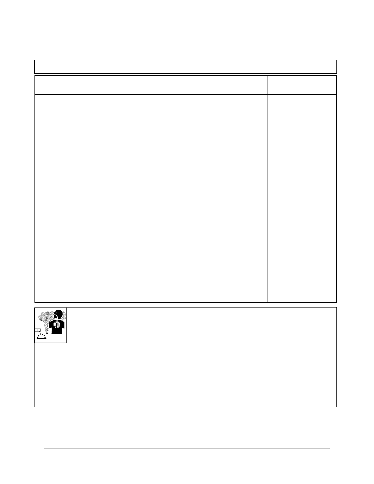
LES VAPEURS ET LESFUMEES SONT
DANGEREUSES POUR LA SANTE.
Le soudage dégage des vapeurs et des fumées
dangereuses à respirer.
1. Eloignez la tête des fumées pour éviter de les respirer.
2. A l’intérieur, assurez-vous que l’aire de soudage est bien ventilée ou que les fumées et les vapeurs sont aspirées à l’arc.
3. Si la ventilation est inadequate, portez un respirateur à adduc-
tion d’air approuvé.
4. Lisez les fiches signalétiques et les consignes du fabricant
relatives aux métaux, aux produitsconsummables, aux revêtements et aux produits nettoyants.
5. Ne travaillez dans un espace confiné que s’il est bien ventilé;
sinon, portez un respirateur à adduction d’air. Les gaz protecteurs de soudage peuvent déplacer l’oxygène de l’air et ainsi
causer des malaises ou la mort. Assurez-vous que l’air est
propre à la respiration.
6. Ne soudez pas à proximité d’opérations de dégraissage, de
nettoyage ou de pulvérisation. La chaleur et les rayons de l’arc
peuvent réagir avec des vapeurs et former des gaz hautement
toxiques et irritants.
7. Ne soudez des tôles galvanisées ou plaquées au plomb ou au
cadmium que siles zones à souder ont été grattées àfond,que
si l’espace est bien ventilé;sinécessaire portez un respirateur
à adductiond’air. Car cesrevêtements et tout métalqui contient
ceséléments peuventdégagerdes fuméestoxiques aumoment
du soudage.
2-2 8-V-96
Page 11
PRECAUTIONS DE SECURITE EN SOUDAGE A L'ARC
Instruction 830002
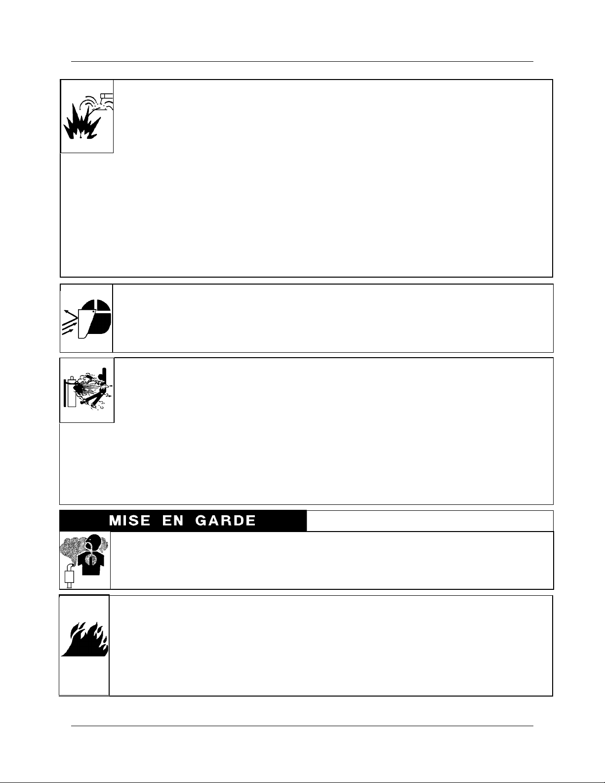
LE SOUDAGE PEUT CAUSER UN INCENDIE OU UNE EXPLOSION
L’arc produit des étincellies et des projections. Les
particules volantes, le métal chaud, les projections
de soudure et l’équipement surchauffé peuvent
causer un incendie et des brûlures. Le contact
accidentel de l’électrode ou du fil-électrode avec un
objet métallique peut provoquer des étincelles, un échauffement
ou un incendie.
1. Protégez-vous, ainsi que les autres, contre les étincelles et du
métal chaud.
2. Ne soudez pas dans un endroit où des particules volantes ou
des projections peuvent atteindre des matériaux inflammables.
3. Enlevez toutes matières inflammables dans un rayon de 10, 7
mètres autour de l’arc, ou couvrez-les soigneusement avec des
bâches approuvées.
LES ETINCELLES ET LES PROJECTIONS BRULANTES PEUVENT
CAUSER DES BLESSURES.
LES BOUTEILLES ENDOMMAGEES
PEUVENT EXPLOSER
Les bouteilles contiennent des gaz protecteurs
sous haute pression.Desbouteilles endommagées
peuvent exploser. Comme les bouteilles font normalement partie du procédé de soudage, traitezles avec soin.
1. Protégez les bouteilles de gaz comprimé contre les sources de
chaleur intense, les chocs et les arcs de soudage.
2. Enchainez verticalement les bouteilles à un support ou à un
cadre fixe pour les empêcher de tomber ou d’être renversées.
3. Eloignez les bouteilles de tout circuit électrique ou de tout
soudage.
4. Méfiez-vous des projectionsbrulantes de soudage susceptibles
de pénétrerdans des aires adjacentespar de petites ouvertures
ou fissures.
5. Méfiez-vous des incendies et gardez un extincteur à portéede
la main.
6. N’oubliez pas qu’une soudure réalisée sur un plafond, un
plancher, une cloison ou une paroi peut enflammer l’autre côté.
7. Ne soudez pas un récipient fermé, tel un réservoir ou un baril.
8. Connectez le câble de soudagele plus près possiblede la zone
de soudage pour empêcher le courant de suivre un long parcours inconnu, et prévenir ainsi les risques d’électrocution et
d’incendie.
9. Ne dégelez pas les tuyaux avec un source de courant.
10. Otez l’électrode du porte-électrode ou coupezle filau tube-contact lorsqu’inutilisé après le soudage.
11. Portez des vêtements protecteurs non huileux, tels des gants
en cuir, une chemise épaisse, un pantalon revers, des bottines
de sécurité et un casque.
Le piquage et le meulage produisent des particules métalliques
volantes. En refroidissant, la soudure peut projeter du éclats de
laitier.
1. Portez un écran facial ou des lunettes protectrices approuvées.
Des écrans latéraux sont recommandés.
2. Portez des vêtements appropriés pour protéger la peau.
4. Empêchez tout contact entre une bouteille et une électrode de
soudage.
5. N’utilisez que des bouteilles de gaz protecteur, des détendeurs,
des boyauxs et des raccords conçus pour chaque application
spécifique; ces équipements et les pièces connexes doivent
être maintenus en bon état.
6. Ne placez pas le visage face à l’ouverture du robinet de la
bouteille lors de son ouverture.
7. Laissez en place le chapeau de bouteille sauf si en utilisation
ou lorsque raccordé pour utilisation.
8. Lisez et respectez les consignes relatives aux bouteilles de gaz
comprimé et aux équipements connexes, ainsi que la publication P-1 de la CGA, identifiée dans la liste de documents
ci-dessous.
LES MOTEURS PEUVENT ETRE DANGEREUX
LES GA Z D’ECHAPPEMENT DES
MOTEURS PEUVENT ETRE MORTELS.
Les moteurs produisent des gaz d’échappement
nocifs.
LE CARBURANT PEUR CAUSER UN INCENDIE OU UNE EXPLOSION.
Le carburant est hautement inflammable.
1. Arrêtez le moteur avant de vérifier le niveau de
carburant ou de faire le plein.
1. Utilisez l’équipement à l’extérieur dans des aires ouvertes et
bien ventilées.
2. Si vous utilisez ces équipements dans un endroit confiné, les
fumées d’échappement doivent être envoyées à l’extérieur, loin
des prises d’air du bâtiment.
2. Ne faites pas le plein en fumant ou proche d’une source
d’étincelles ou d’une flamme nue.
3. Si c’est possible, laissez le moteur refroidir avant de faire le
plein de carburant ou d’en vérifier le niveau au début du
soudage.
4. Ne faites pas le plein de carburant à ras bord: prévoyez de
l’espace pour son expansion.
5. Faitesattention de ne pas renverserde carburant. Nettoyeztout
carburant renversé avant de faire démarrer le moteur.
8-V-96 2-3
Page 12
PRECAUTIONS DE SECURITE EN SOUDAGE A L'ARC
Instruction 830002
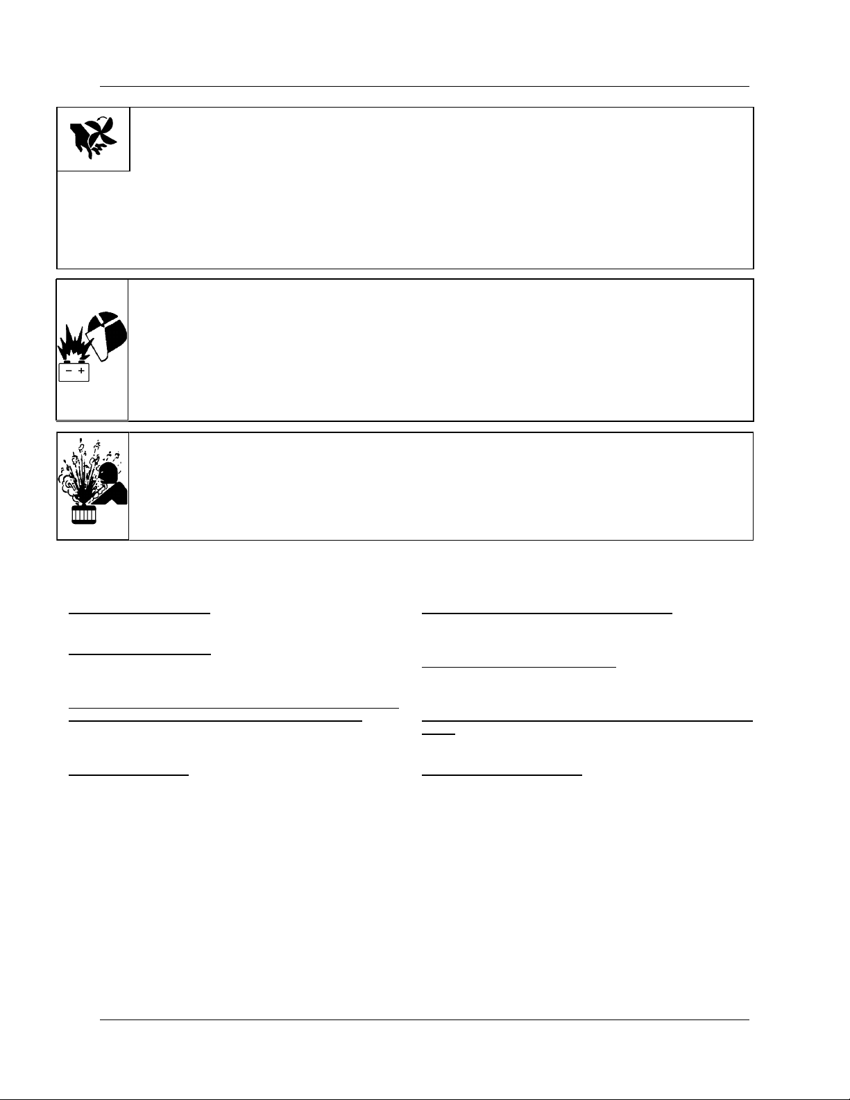
DES PIECES EN MOUVEMENT PEUVENT CAUSER DES BLESSURES.
Despièces en mouvement,tels desventilateurs, des
rotors et des courroies peuvent couper doigts et
mains, ou accrocher des vêtements amples.
1. Assurez-vous que les portes, les panneaux, les capots et les
protecteurs soient bien fermés.
2. Avant d’installer ou de connecter un système,arrêtez le moteur.
DESETINCELLESPEUVENT FAIREEXPLOSER UN ACCUMU LATEUR;
L’ELECTROLYTE D’UN ACCUMULATEUR PEUT BRULER LA PEAU ET
LES YEUX.
Les accumulateur s contiennent de l’électr oly te
acide et dégagent des vapeurs explosives.
LA VAPEUR ET LE LIQUIDE DE REFROIDISSEMENT BRULANT SOUS
PRESSION PE UVENT BRULER LA
PEAU ET LES YEUX.
Le liquide de refroidissement d’un radiateur peut
être brûlant et sous pression.
3. Seules des personnes qualifiées doivent démonter des protecteurs ou des capots pour faire l’entretien ou le dépannage
nécessaire.
4. Pour empêcher un démarrage accidentel pendant l’entretien,
débranchez le câble d’accumulateur à la borne négative.
5. N’approchez pas les mains ou les cheveux de pièces en mouvement; elles peuvent aussi accrocher des vêtements amples
et des outils.
6. Réinstallez les capots ou les protecteurs et fermez les portes
après des travaux d’entretien et avant de faire démarrer le
moteur.
1. Portez toujours un écran facial en travaillant sur un accumulateur.
2. Arrêtez le moteur avant de connecter ou de déconnecter des
câbles d’accumulateur.
3. N’utilisez que des outils anti-étincelles pour travailler sur un
accumulateur.
4. N’utilisez pas une source de courant de soudage pour charger
un accumulateur ou survolter momentanément un véhicule.
5. Utilisez la polarité correcte (+ et –) de l’accumulateur.
1. N’ôtez pas le bouchon de radiateurtant que le moteur n’est pas
refroidi.
2. Mettez desgantset posez un torchon sur lebouchon pour l’ôter.
3. Laissez la pression s’échapper avant d’ôter complètement le
bouchon.
PRINCIPALES NORMES DE SECURITE
Safetyin WeldingandCutting, normeANSI Z49.1,American Welding
Society, 550 N.W. LeJeune Rd., Miami, FL 33128.
Safety and Health Standards, OSHA 29 CFR 1910, Superintendent
of Documents, U.S. Government Printing Office, Washington, D.C.
20402.
Recommended Safe Practices for the Preparation for Welding and
Cuttingof ContainersThatHave HeldHazardousSubstances, norme
AWS F4.1, American Welding Society, 550 N.W. LeJeune Rd.,
Miami, FL 33128.
National Electrical Code, norme 70 NFPA, National Fire Protection
Association, Batterymarch Park, Quincy, MA 02269.
Safe Handling of Compressed Gases in Cylinders, document P-1,
Compressed Gas Association, 1235 JeffersonDavis Highway, Suite
501, Arlington, VA 22202.
Code for Safety in Welding and Cutting, norme CSA W117.2 Association canadienne de normalisation, Standards Sales, 276 Rexdale
Boulevard, Rexdale, Ontario, Canada M9W 1R3.
Safe Practices for Occupation and Educational Eye and Face Protection, norme ANSI Z87.1, American National Standards Institute,
1430 Broadway, New York, NY 10018.
Cutting and Welding Processes, norme 51B NFPA, National Fire
Protection Association, Batterymarch Park, Quincy, MA 02269.
2-4 8-V-96
Page 13
DESCRIPTION OF EQUIPMENT
DESCRIPTION OF EQUIPMENT
430429-238
General
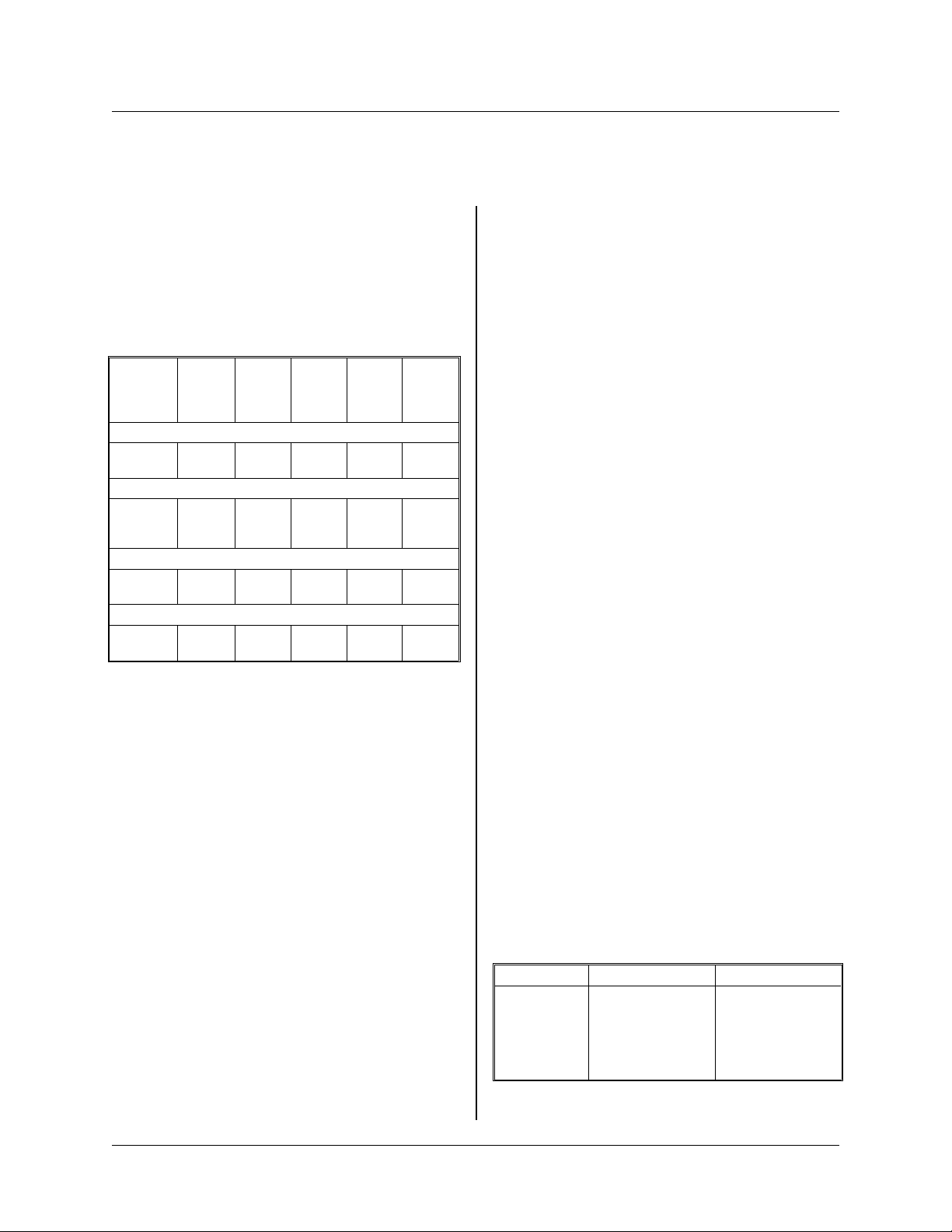
The Mega-Arc®welding machines are constantcurrent transformer type DC units that provide voltampere curves that are basically drooping, with a
slight slope.
See Table 3-1 for rated output of the models
covered by this manual.
No
Spec
No Amps
6031A-36
032A-3
6036A-3
6036B-3
6037A-3
6041A-4
6042A-3
6046A-3
6047A-3
Load
Volts
Model No. MA-3
300
300
400
400
400
500
500
750
750
32
32
Model No. MA-4
32
32
32
Model No. MA-5
40
40
Model No. MA-7
44
44
Load
Volts kW
80
80
80
80
80
85
95
85
85
9.6
9.6
12.8
12.8
12.8
14.4
14.4
33
33
Duty
Cycle
35%
35%
35%
35%
35%
40%
40%
40%
40%
SCRs (Silicon Controlled Rectifiers) are energized,
andopen-circuitvoltage(OCV) is applied towelding
output terminals. In REMOTE (UP) position, a remote switch must be used.
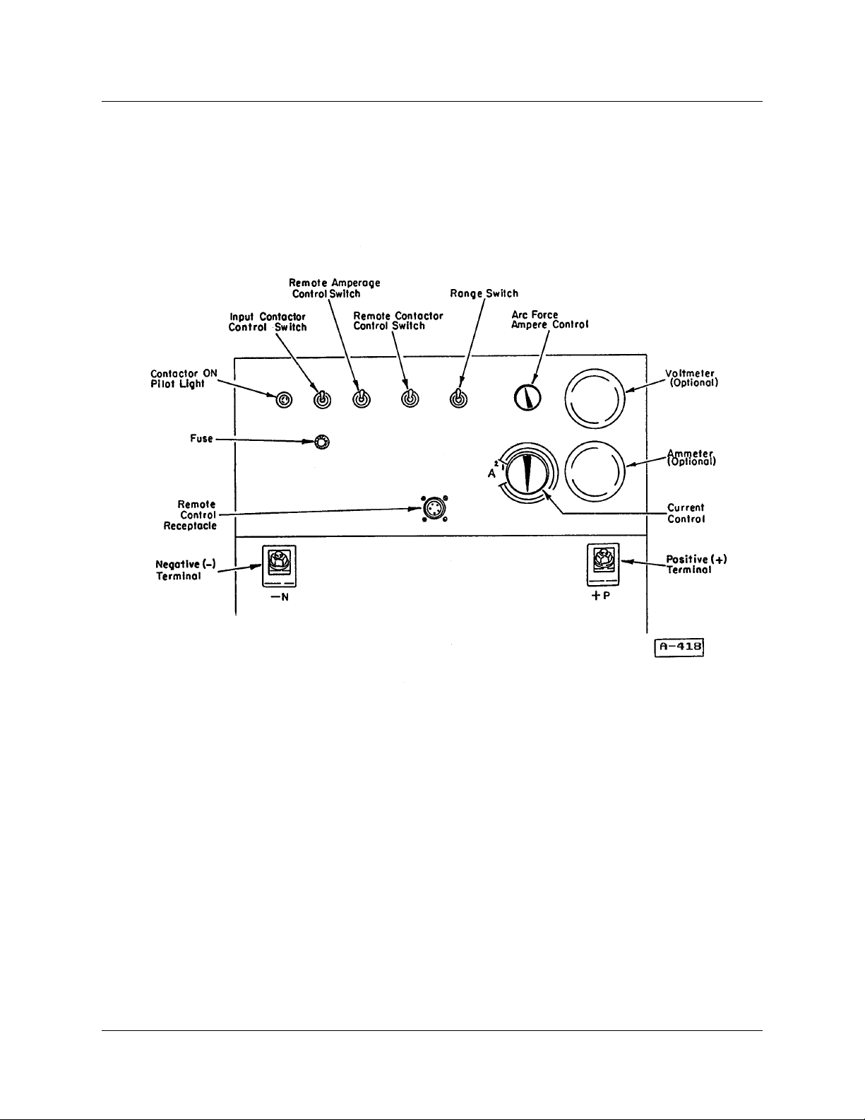
RANGE SWITCH, LOW/HIGH Range–Thewelding current range suitable for the work application
and electrode selection will be chosen by this
switch. See Table 3-2 for current ranges.
ARC FORCE AMPERE CONTROL – Varies the
short-circuit (welding arc) current and produces an
increaseofamperagewhen arc length isshortened,
suchasinatightgroove. This control providesmore
arcforceand eliminatesthetendencyof snuffingout
the arc, when using electrode manipulation. The
control is especially suited for use with E-6010 and
E-7018 electrodes for pipe welding applications.
See NOTE at paragraph5 in OPERATION chapter.
CURRENT CONTROL – Adjusts the welding current. See Table 3-2 for ranges of control.
VOLTMETER (Optional) – Indicates the OCV or
welding voltage of the arc, if welding arc is established.
AMMETER (Optional) – Indicates the amperage
of the welding arc, when an arc is established.
Table 3-1
Controls And Connections
INPUT CONTACTOR “ON” Pilot Light – Indicates
when the contactor is closed for power ON modeof
the unit.
INPUTCONTACTOR CONTROL ON/OFF Switch
– This toggle switch is the master power switch for
the welding machine, and must be in the ON position before any other section will operate. The primary circuit of the control transformer is energized
whenever line voltage is present at the input terminals. This switch closes the secondary circuit of the
control transformer, energizing the contactor,which
energizes the power transformer. See DANGER in
Safety Warning chapter included in this manual.
REMOTE AMPERAGE CONTROL “LOCAL-REMOTE” Switch – Selects either the LOCAL (panel
mounted) current control, or some remote control
device to control welding current.
REMOTECONTACTOR CONTROL “LOCAL-REMOTE” Switch – In LOCAL (DOWN) position, the
POSITIVE TERMINAL (+) – Serves asconnection
point for the welding lead to the workpiece when
straight polarity is used.
NEGATIVE TERMINAL (−) – Serves as connection point for theelectrode lead when straightpolarity is used.
REMOTE CONTROL RECEPTACLE – Serves as
connection point for the Remote Control Pendant.
FUSE - 3 A
Welding Current Ranges
Model Range 1 (Low) Range 2 (High)
MA-3
MA-4
MA-5
MA-7
10 TO 120 A
15 TO 185 A
20 TO 240 A
30 TO 350 A
Table 3-2
20 TO 300 A
30 TO 400 A
40 TO 500 A
60 TO 750 A
December 1, 1997 Revised 3-1
Page 14
430429-238
DESCRIPTION OF EQUIPMENT
Figure 3-1 Control Panel
3-2 December 1, 1997 Revised
Page 15
INSTALLATION
Location
For best operatingcharacteristics and longest unit
life, take care in selecting an installation site. Avoid
locations exposed to high humidity, dust, high ambienttemperature,orcorrosivefumes.Moisturecan
condense on electrical components, causing corrosionorshorting of circuits.Dirtoncomponents helps
retain this moisture.
Adequate air circulation is needed at all times in
order to assure proper operation. Provide a minimumof 12 inches (305 mm) of freeairspaceatboth
front and rear of the unit. Make sure that the ventilator openings are not obstructed.
Internal Wiring Check
Refer to the product identification plate (nameplate) on the welding machine’s control panel to
determine the power input voltages and frequency
at which it will be operated.
Removecabinettopfor access to LINE VOLTAGE
CHANGEOVER circuitry. Check line voltage connections against instructions on VOLTAGE
CHANGEOVER DIAGRAM supplied with this manual. If necessary, rearrange internal wiring and/or
link connections.
430429-238
INSTALLATION
DANGER: ELECTRIC SHOCK
CAN KILL. Open the disconnect switch, or breaker, and
determine that no voltage is
present, before connecting
wires between welding machine and power supply.
CAUTION: The method of installation,
conductor size, and overcurrent protection shall conform to the requirements
of the local electrical code, the National
ElectricalCode, or other national codes,
as applicable. All installation wiring and
machine reconnection shall be done by
qualified persons.
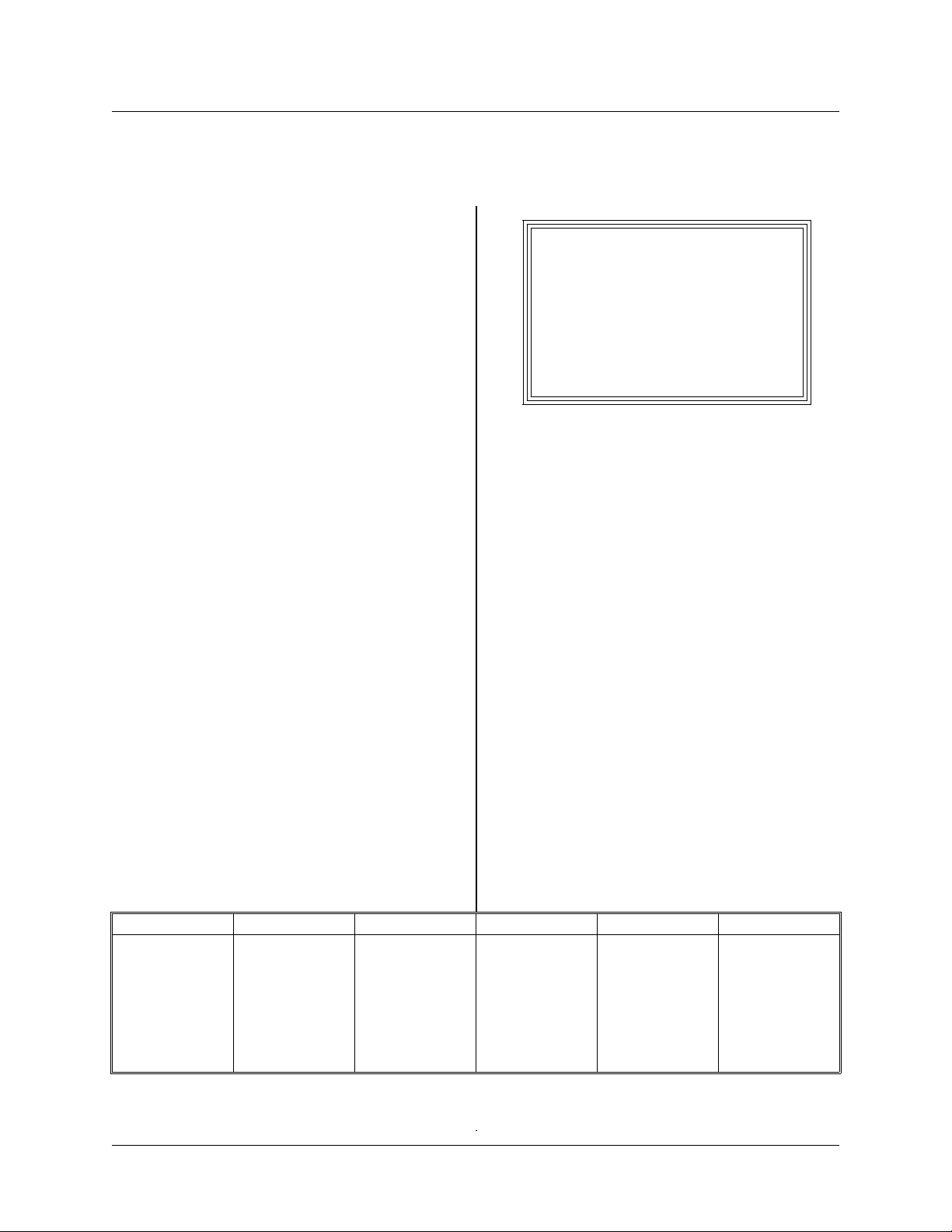
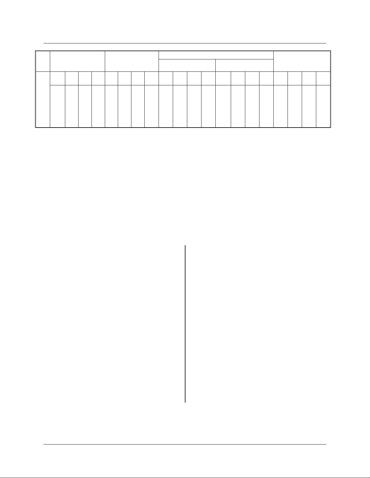
Table 4-2 provides minimal information for selection of line conductors, fuses, and the equipment
grounding conductor. This information is from the
National Electrical Code NFPA 70-1981 Edition.
Install this equipment per the latest edition, available from the National Fire Protection Association,
470AtlanticAvenue,Boston,MA 02210.SeeCAUTION above.
Connecting Welding Machine To
Line Voltage
The input power should be connected to the unit
through a fused disconnect switch, or othersuitable
disconnecting means furnished by the user. A hole
is provided in the rear panel of themachine, near to
the input connections, for the entry of the input
conductors.
Spec. No. Line volts Line Amps Phase Hz kW
6031A-3
6032A-3
6036A-3
6036B-3
6037A-3
6041A-4
6042A-3
6046A-3
6047A-3
December 1, 1997 Revised 4-1
220/380/415
380/500
220/380/415
220/380/415
380/500
220/380/415
380/500
220/380/415
380/500
64.5/37.5/34.5
37.5/28.5
84/48/44
84/48/44
48/36.5
114/66/60
66/50
172/100/91
100/76
Table 4-1 Input Voltage Data
Connect the three-phase line leads to terminals
L1, L2, and L3 on the line contactor inside the
welding machine cabinet.
Grounding
The frame of this welding machine should be
grounded for personnel safety, and to assure operationoftheovercurrentprotection.Thegrounding
method, and the equipment grounding conductor
3
3
3
3
3
3
3
3
3
50/60
50/60
50/60
50/60
50/60
50/60
50/60
50/60
50/60
14.3
14.3
18.5
18.5
18.5
24.9
24.9
38
38
Page 16
430429-238
INSTALLATION
Line
Volts Full Load amps
•3••4◊5◊◊
84
64.5
220
380
415
500
• 6031A-3
6032A-3
* Conductor size shall be modified as required for line voltage drop and ambient temperature. Sizes listed for
conduit installation are based on 90°C conductor insulation, designated as FEP, FEPB, RHH, and THHN.
37.5
34.5
28.5
48
44
36.5
73457**3**4
172
114
100
66
91
60
76
50
••6036A-3
6036B-3
6037A-3
Approx. Line
Fuse Rating
#8
225
150
125
90
50
50
40
Table 4-2 Recommended Wire and Fuse Size Table
90
70
90
70
70
50
◊ 6041A-4
6042A-3
150
125
110
#8
#8
#8
Copper Line Wire Size* Copper Grd.
In Conduit Flexible Cable
***5***7**3**4***5***7**3**4***5***
#8
# 8
#2
#4
#6
#8
#8
#8
#8
#8
#8
◊◊ 6046A-3
#6
#6
#6
6047A-3
# 8
# 8
#10
#8
#8
#8
#8
#8
#8
#8
Conductor - Min.
#6
#10
#10
#10
#8
#10
#10
#10
#8
#8
#10
#4#8#10
** 35% duty cycle
*** 40% duty cycle
7
#6
#8
#8
#8
size and type shall conform to local and national
codes.
For the National Electrical Code, the equipment
grounding conductor shall be green, green with a
yellow stripe, or bare.
If flexible power cableis used, usea cable assembly which includes the equipment grounding conductor. If metallic armored cable or conduit is used,
the metal sheathing or conduit must be effectively
grounded per local and national codes.
Rubber-tiremountedequipment shallbegrounded
to conform tolocal and national codes.The grounding assists in providing protection against line voltage elec trical shock and static shock. The
grounding serves to discharge the static electric
charge w hich tends to build up on rubber-tire
mounted equipment. This static charge can cause
painful shock and lead to the erroneous conclusion
that an electrical fault exists in the equipment.
If a system ground is not available, consult the
electrical code enforcement body for instructions.
The welding machine should be connected to an
adequate driven ground rod, or to a water pipe that
entersthe ground not more than 10 feet(30 meters)
from the machine.
The equipment grounding conductor size is listed
in Table 4-2 as a guide, if no local or national code
is applicable.
Attach the equipment grounding conductor to the
stud provided adjacent to the contactor. Determine
that the ground wire size is adequate before the
machine is operated.
Caution: Be sure to replace the cabinet
top to assure adequate internal ventilation and prevent component failure.
Welding Leads
Use Table 4-3 for selection of the proper size
copper welding leads.
4-2 December 1, 1997 Revised
Page 17

430429-238
INSTALLATION
TOTAL LENGTH OF LEAD CIRCUIT IN FEET (AND METERS)
Welding
Current
Amperes
100
150
200
250
300
350
400
450
Tableshowsweldingleadsizesrecommendedforvarious lengths of leads. Footageshownincludescomplete
welding (secondary) circuit, both electrode and work leads. Lead size shown is for 90°C insulation, 30°C
(86°F) ambient, and not over 4.5 volts lead drop.
50 Feet
(15.2 M)
#4
#4
#2
#1
#1/0
#1/0
#2/0
#2/0
(ELECTRODE LEAD PLUS WORK LEAD)
100 Feet
(30.5 M)
#4
#2
#1
#1
#1/0
#2/0
#2/0
#2/0
150 Feet
(45.7 M)
#2
#1
#1/0
#2/0
#3/0
#3/0
#4/0
#4/0
200 Feet
(61.0 M)
#1
#1/0
#2/0
#3/0
#4/0
#4/0
–
–
250 Feet
(76.2 M)
#1
#2/0
#3/0
#4/0
–
–
–
–
Table 4-3 Welding Leads
December 1, 1997 Revised 4-3
Page 18
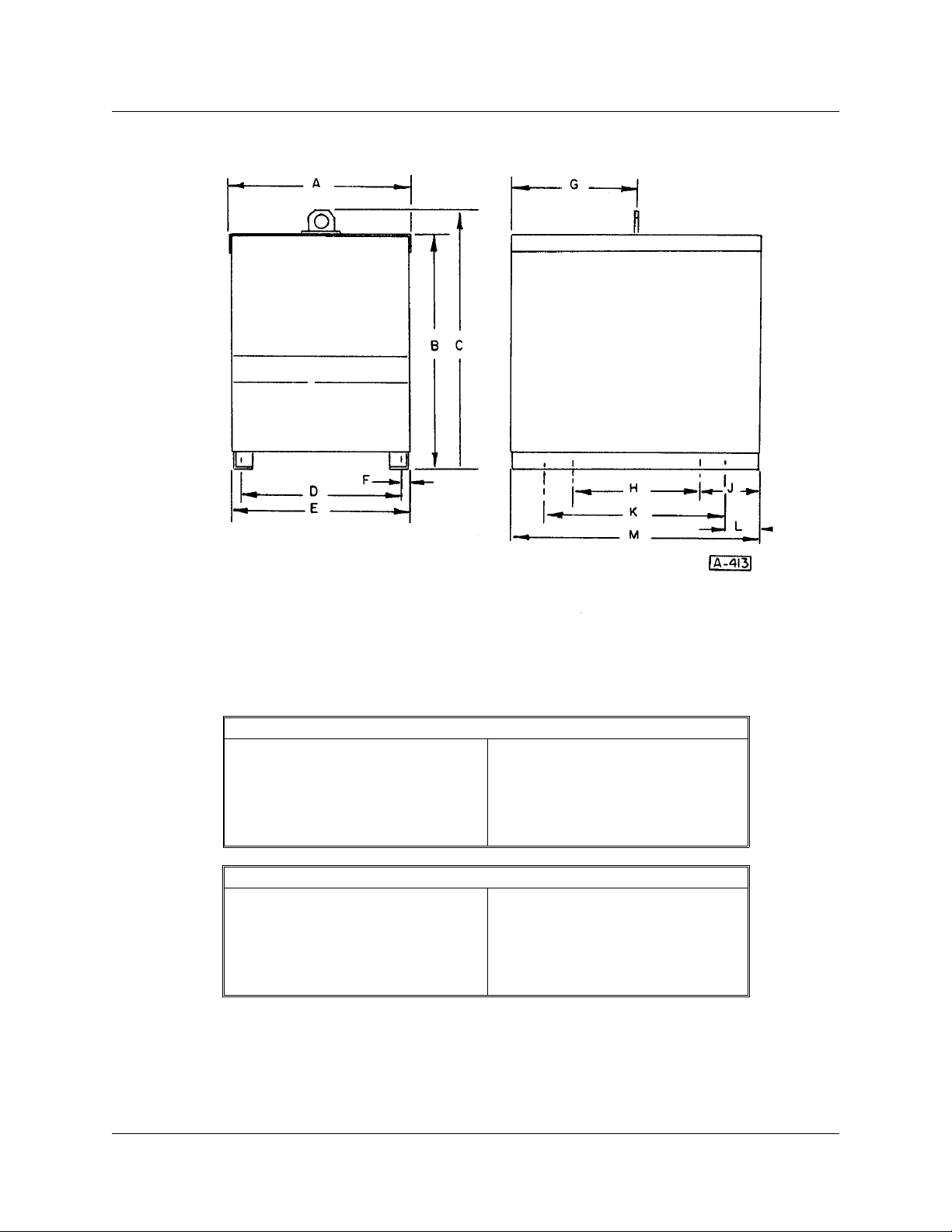
430429-238
INSTALLATION
MA-3, MA-4, MA-5
A 21-1/2 in. (546 mm)
B 26-1/2 in. (673 mm)
C 29-1/2 in. (749 mm)
D 19-3/4 in. (502 mm)
E 21-3/8 in. (543 mm)
F 13/16 in. (21 mm)
G 14-9/16 in. (370 mm)
H 14-3/4 in. (375 mm)
J 7-3/16 in. (183 mm)
K 20-3/4 in. (527 mm)
L 4-3/16 in. (106 mm)
M 29-1/8 in. (738 mm)
MA-7
A 24-1/2 in. (616 mm)
B 26-1/2 in. (673 mm)
C 29-1/2 in. (749 mm)
D 22-1/2 in. (572 mm)
E 21-0 in. (610 mm)
F 3/4 in. (19 mm)
G 16-3/16 in. (411 mm)
H 19-3/4 in. (502 mm)
J 7-3/16 in. (183 mm)
K 25-3/4 in. (654 mm)
L 4-3/16 in. (106 mm)
M 34-1/8 in. (867 mm)
Figure 4-1 Outline Dimensions
4-4 December 1, 1997 Revised
Page 19

OPERATION
430429-238
OPERATION
Sequence Of Operation
1. Set INPUT CONTACTOR CONTROL Switch to
ON (UP) position. Themechanicalcontactor should
close, and the amber pilot light on the panel should
be illuminated.The mechanical contactor energizes
the Main Power Transformer, which energizes the
fan motor.
2.ForLOCALcontrol,settheREMOTE CONTACTORCONTROL Switch and the REMOTE AMPERAGE CONTROL Switch to LOCAL (DOWN)
position. The REMOTE CONTACTOR CONTROL
Switch energizes the SCRs (see Connection Diagram in DIAGRAMS chapter) and open-circuit voltageisappliedto the outputterminals.TheREMOTE
AMPERAGE CONTROL Switch allows control by
the CURRENT CONTROLpotentiometer located in
the center of the front panel.
3. For REMOTE control,set the aboveswitches to
REMOTE (UP) position. For this mode of operation
it will be necessary to use a REMOTE CONTROL
PENDANT, plugged into the REMOTE CONTROL
RECEPTACLE, in order to energize the SCRs and
control the current. The two remote switches work
independently of each other. The following combinations can be accomplished:
a. Remote welding contactor control.
b. Remote current control.
c. Both of the above at the same time.
4.TheRANGESWITCHsettingwill be determined
by the work application, considering characteristics
of the workpiece and electrode. LOW range is designated as number 1 and HIGH range is number 2.
5. The ARC FORCE AMPERE CONTROL potentiometer varies the dynamic slope of the volt-amp
curves. It essentially changes the short-circuit (arc)
current. Turning the potentiometer knob clockwise
causes forceful arc initiation, with a hard-driving arc
maintained.Turningtheknobcounterclockwisecreates a softer start, with a smooth arc.
NOTE: When using GTAW (TIG) and
Plasma Processes, it is recommended that
the Arc Force Control be set to
setting.
minimum
The setting of the potentiometer is dependent
upon the type of jointand the electrodebeing used.
See paragraph entitled ARC FORCE AMPERE
CONTROL under DESCRIPTION OF EQUIPMENT chapter included in this manual.
High Frequency Considerations
When operating the unit in a high frequency atmosphere, or with a highfrequencyattachment, the
following guidelines should be adhered to, to minimize interference.
1. Turn the high frequency intensity on machines
or attachments to the lowest level which will not
interfere with arc starting.
2. Use the shortest possible TIG Torch cable and
do not route it with other control cables and power
cables.
3. Make certain thatall equipment cases areearth
grounded. A large ground wire between a high
frequency attachment case and ground is helpful.
4. Do not coil power cables on control cables. It is
best to route cables on the floor rather than overhead and among other cables. (This minimizes
antenna effects.)
5. The input power cable to a high frequency
attachment should be as short as possible.
6. The input leads to the power source should be
contained in solid metal conduit whenever possible.
When TIG welding at very low current (less than
30 amperes), a jumper plug can bechanged on the
printed circuit board (369511) to insure that the
open-circuit voltage will stay at maximum value.
This will reduce the possibility of high frequency
interference when operating at low reference voltages. In order to make this change, follow this
procedure:
1. Remove the left side panel.
2. At the bottom of the printed circuit board there
is a plug labeled J6. (See Figure 7-5 in TROUBLESHOOTING Chapter.) Remove this plug from
pins 1 and 2, and place it on pins 2 and 3.
3. Replace side panel.
December 1, 1997 Revised 5-1
Page 20

430429-238
OPERATION
This page intentionally left blank.
5-2 December 1, 1997 Revised
Page 21

MAINTENANCE
430429-238
MAINTENANCE
Lubrication
The fan motor incorporates sleeve bearings. You
can expect the life of this motor to exceed 50,000
hours without relubrication. Periodically cleaning
the motor and lubricating the bearings will extend
the life of the motor. The following table will furnish
a recommended guide as to the frequency of this
lubrication if desired.
Type of Duty
Light (up to 6 hrs./day)
Moderate (7 to 15 hrs./day
Heavy (16 to 24 hrs./day)
NOTE: Apply 1-12 drops of 20W non-detergent oil at each end of bearing.
Lubrication
Interval
Every 12 mo.
Every 6 mo.
Every 3 mo.
Inspection And Cleaning
For uninterrupted, satisfactory service from this
welding machine, it is necessary to keep the machine clean, dry, and well ventilated. At least every
threemonths,ormoreoftenasnecessary,wipeand
blow out all dirt from the machine’s internal components,withairpressureofnotover25psi(172kPa).
Be sure to wipe the fan blades clean.
Check and tighten all electrical connections as
necessary to eliminate unnecessary losses and to
avoid subsequent troublefrom overheating oropen
circuits. Check for broken wiring or damaged insulation on wiring.
WARNING: Disconnect line voltagefromtheunitbefore attempting any servicing inside unit.
Turn off fused disconnect
switch that supplies power to
welding machine, and remove
its fuses.
CAUTION: The flow of air through the
weldingmachineiscarefullydirected by
baffles. Never operate the welding machine with any of the side or top panels
removed or open, as serious damage to
the rectifiers might result.
December 1, 1997 Revised 6-1
Page 22

430429-238
MAINTENANCE
This page intentionally left blank.
6-2 December 1, 1997 Revised
Page 23

430429-238
TROUBLESHOOTING
TROUBLESHOOTING
The following chart contains information which can be used to diagnose and correct unsatisfactory operation or failure of the various components of the welding machine. Each symptom of trouble is followed by
a list of probable causes and the procedure necessary to correct the problem. In addition to the chart, detailed instructions for checking and adjusting and/or setting components on the Printed Circuit Board and
SCRs are given.
Troubleshooting Guide
Welding machine will not start.
Power switch OFF
Place power switch in ON position.
Power lines dead
Check voltage.
Broken power lead
Repair.
Wrong line voltage
Check power supply.
Incorrect input power connections at welding machine
Check connections against wiring diagram.
Open circuit to power switch or control transformer
Repair. Check for broken wire or loose connections at terminals.
Fuse on control transformer blown
Remedy cause. Replace fuse.
Line contactor fails to close.
Defective coil
Replace.
Mechanical obstruction on contactor
Remove.
Broken leads at line contactor
Repair.
Contactor chatters.
Line leads too small
Use larger leads.
Low line voltage
Check line voltage.
December 1, 1997 Revised 7-1
Page 24

430429-238
TROUBLESHOOTING
Contactor operates and blows link fuses.
Wrong line voltage
Check nameplate of welding machine for line voltage to use; check line voltage.
Links on voltage changeover board incorrectly connected
Check wiring diagrams for link positions; connect links correctly.
Line fuse too small
Install proper size fuse.
SCR failure
See Silicon Controlled Rectifier Testing.
Short circuit in primary connections
Remove short circuit.
Transformer failed
Replace transformer.
Unit delivers welding current but soon shuts down.
Welding machine overloaded
Reduce load, overload can be carried only for a short time.
Duty cycle too high
Do not operate continually at overload currents.
Power leads too long or too small in cross section
Replace with larger diameter cable.
Ambient temperature too high
Operate at reduced loads when temperature exceeds 104°F (40°C).
Ventilation blocked
Check air intake and exhaust openings to be unobstructed.
Fan not operating
Check bearings, disconnect leads and apply motor nameplate voltage to test.
Contactor operates, but welding machine will not deliver welding current, and
open circuit voltage is present at the output when gun switch is depressed.
No ground connections at work
Make connections.
Welding leads not connected
Make connections.
Current control does not control welding current.
Potentiometer burned out
Contact factory.
7-2 December 1, 1997 Revised
Page 25

430429-238
TROUBLESHOOTING
Loose connections in voltage control circuit
Check connections.
Control circuit board failure
See Detailed Setting and Troubleshooting of PC Board.
Fan not operating (also see causes and remedies under “Welding machine will
not start”).
Motor failed
Replace or repair.
Broken lead or connection to fan motor
Repair wiring.
Blown fuse on front panel of welding machine
Replace; 115-volt circuit may be overloaded.
Operator gets shock when welding machine case is touched.
Case of welding machine not grounded
Ground welding machine case.
Abnormal current fluctuation, voltage nearly constant.
Loose cable connections
Check for overheated connections and tighten.
Control board failure
See Detailed Setting and Troubleshooting of PC Board.
Contactor fails to open.
Contactor contacts sticking
Clean contacts.
Very noticeable, rough, sputtering arc. Loss of control. Minor starting problems.
Control circuit board failure
See Detailed Setting and Troubleshooting of PC Board.
December 1, 1997 Revised 7-3
Page 26

430429-238
TROUBLESHOOTING
Detailed Troubleshooting
Instructions
The Mega-Arc®machines are solid-state welding
machines. The method of troubleshooting is different, but it is not more difficult than troubleshooting
aconventional unit. Do not overlook the obvious. As
inthecaseofallelectrical equipment,looseconnections are the primary cause of malfunction both
internal and external to the power source. Do not
overlook bad grounds, shorted control cables,
wrong settings, blown fuses, worn contactors, misconnections from auxiliary equipment, misapplications, etc. The only equipment needed to properly
detect a problem on this power source is a simple
voltohmmeter, although an oscilloscope is the best
method to quickly “see” the problem.
Voltages
Refer to Diagram 369704
1. Across the secondary on all three phases:
120 V AC ±10% MA-3, MA-4
130 V AC ±10% MA-5, MA-7
2. From the center bus bar on secondaries to the
top or bottom of the secondary:
60 V AC ±10% MA-3, MA-4
65 V AC ±10% MA-5, MA-7
3. X4-X5 on “B” phase: 115 V AC ±10%.
4. Control transformer: 115 V AC ±10%. (See
Voltage Changeover Diagram.)
5. X1-X3 on fuse block: 33 V AC ±10%.
6. X1-X2 and X2 to X3 from fuse block to output
rectifier: 16.5 V AC ±10%.
NOTE: The ± 10% valueindicates the possibilityofhavingahighorlowvoltageon the
input line.
Symptoms
PC BOARD FAILURE — If a board failure occurs,
the following situations will probably happen:
1. Loss of welding arc completely.
2. Rough, sputtering arc, very noticeable.
3. Loss of welding arc control.
4. Difficulty in starting arc.
MALFUNCTION IN SCRs — The following condi-
tions will probably exist:
1. Blown line fuses in the case of a shorted SCR
(similar to a shorted diode).
2. One SCR does not turn on (either it is open, or
gate signal is not being received by the SCR [gate
circuit open]) and a very small change will occur at
the welding arc, and will be difficult to detect by the
averageweldingoperator.Generally when this happens, it will be necessary to adjust the current
control on thefront of the power source(see Figure
3-1), increasing the current to obtain the same
welding current that wasbeing produced before the
SCR defect occurred.
3. Two SCRs do not turn on, the welding arc
becomes erratic and unstable.
Open Circuit Voltage Test
If the power source is suspected, a very simple
test can tell you a great deal about the power
source. Observe the open-circuit voltage of the
machine by placing a voltmeter across the output
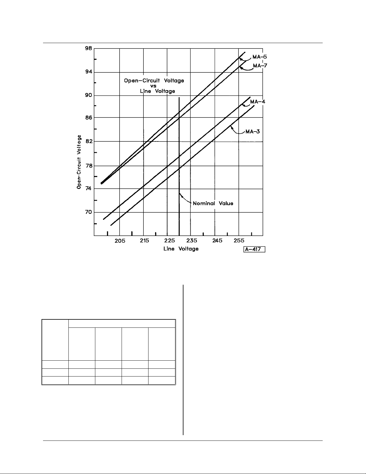
terminals. The voltage reading should be approximately 80 V DC on the MA-3 and MA-4; 85 V DC
on the MA-5 and MA-7.
If the voltage is not equal or close to this voltage,
there is something wrong with the power source.
Note that thisvoltage was observedat normal input
line voltage (230 volts, for example). It will vary
according to the line voltage. If the 80 or 85 V DC
is observed, there is a very good chance that the
power source is operating properly. See Open-circuit Voltage vs. Line Voltage curve, Figure 7-1, for
open-circuit voltage variation as a function of line
voltage.
NOTE: It is important to note that in the
LOW range (see Table 3-2), at minimum
settingontheCurrent Control, the open-circuit voltage will drop to a lower value and
possibly appear to be unstable (fluctuate).
This is not a malfunction, but a normal
situation.
Printed Circuit Board Testing
The next step isto check thePrinted Circuit Board
inside the unit. For complete details, see Detailed
Setting and Troubleshooting of Printe d Circuit
Board and also Figure 7-5.
Silicon Controlled Rectifier (SCR) Testing
In the case of a severe malfunction such as a
shorted SCR, do not turn the unit ON. Disconnect
the leads from the transformer to the heat sink
assembly, and check with VOM for shorted SCRs.
7-4 December 1, 1997 Revised
Page 27
430429-238
TROUBLESHOOTING
Figure 7-1
An open gate or an open SCR cannot be checked
with a VOM. If an SCR is not firing, the open-circuit
voltage will shiftdown. Check the following table for
typical values.
MAX. OCV
Three
Not
Firing
MA-3
All
SCRs
One
Not
Firing
Two
Not
Firing
Firing
80 V DC 73 V DC 66 V DC 53 V DC
MA-4 80 V DC 73 V DC 66 V DC 53 V DC
MA-5 85 V DC 77 V DC 69 V DC 61 V DC
MA-7 85 V DC 77 V DC 69 V DC 61 V DC
Table 7-1
NOTE: The above valuesinTable7-1 were
recorded at nominal line voltage.
ISOLATING MALFUNCTIONING SCR — This is
best done by trial-and-error method. Use Diagram
369704 as reference while inspecting the unit. On
the output rectifier heat sink there are two surge
suppressor boards, each having three terminals.
The leads connected to these terminal strips are
providing the gate signal to the SCRs. The wires
fromtheothersideof the terminalstripstotheSCRs
are white wires, in all cases.
Turnthe Current Control to maximumposition and
begin disconnecting the leads from the terminals,
one at a time. As the first lead is disconnected,
observe the open-circuit voltage of the machine. If
the OCV drops to a lower value, it will indicate that
this particular SCR is working properly. Reconnect
this lead, and proceed to do the same with the
remaining five leads until you discover which disconnection does not cause the OCV to drop to a
lower level. This will be the SCR which should be
changed. See Mounting Procedure for SCRs.
December 1, 1997 Revised 7-5
Page 28
430429-238
TROUBLESHOOTING
Mounting Procedure for SCRs
1. Thoroughly clean heat sink surface to eliminate
any dirt or contamination.
2. Apply a thin coat of Alcoa #2 compound to
cleanedsurface. Alcoa #2 is available from Thermal
Arc, part number 903870.
3. Positively locate the SCR in place in the heat
sink. A small springpinin the extruded heat sinkwill
locate the SCR.
4.Placethe clampinposition withtheboltsthrough
the holes in the heat sink, and proceed in following
manner.
5. Tighten the nuts evenly until finger tight.
6. Tighten each bolt 1/2 turn, using a 7/16 inch
socket wrench on the bolt heads.
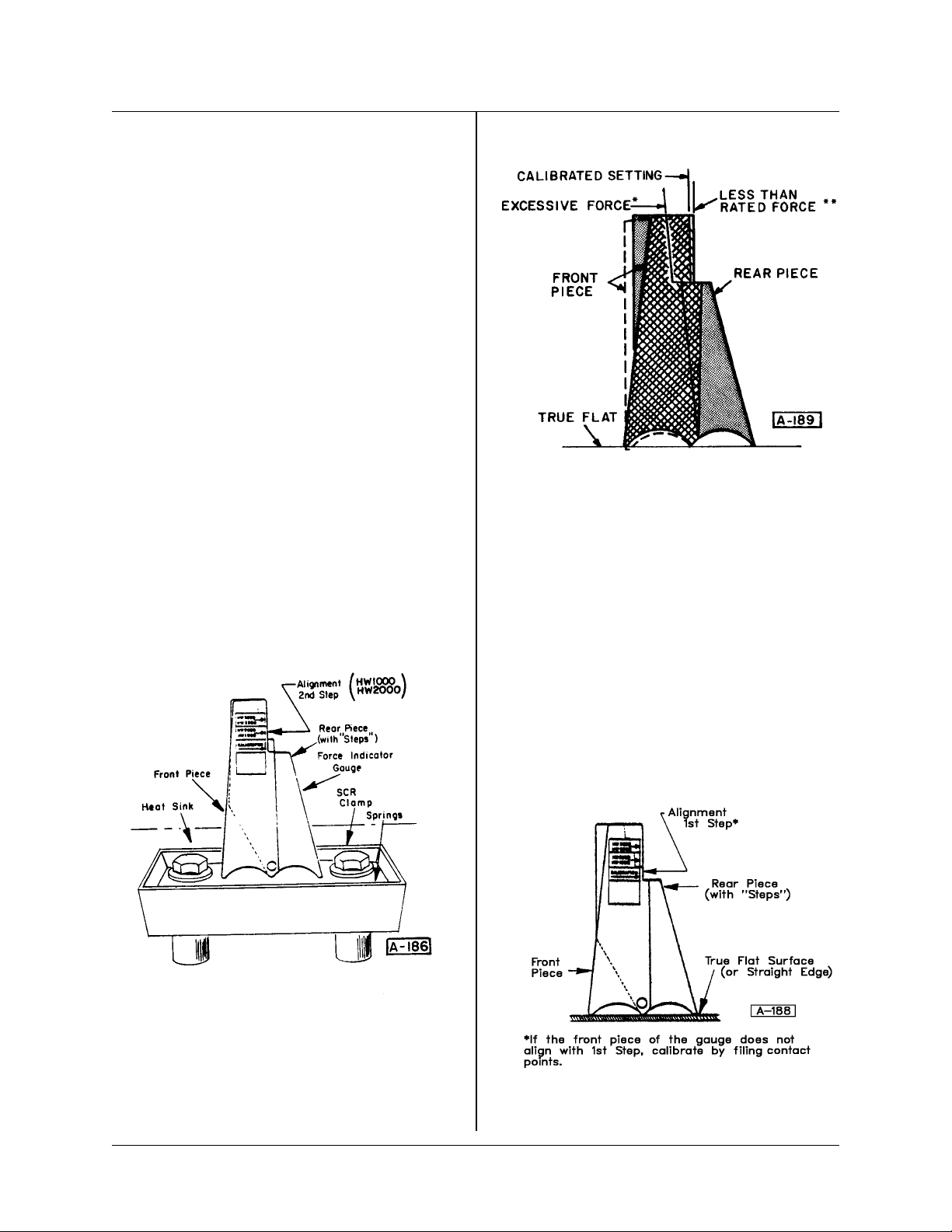
7. Place the Force Indicator Gauge* firmlyagainst
thespring,asshowninFigure7-2,sothat both ends
and the middle are in solid contact with the spring.
The “steps” onthe rear piecewillindicate the spring
deflection, or force, by its relationship to the alignment edge on the front piece of the gauge. Correct
mounting force is indicated when the steps are
aligned with the edge, as shown in Figure 7-2. For
the MA-5, MA-7 machines, align to Step 2.
Figure 7-3
*Excessive Force – Loosen nuts and start over.
NEVERtrytoadjust springforceby backingoffnuts,
as spring tension will give false readings. Always
start at Paragraph 5.
Figure 7-2
**Less Than Rated Force – Tighten nuts alternately 1/4 turn at a time until gauge readings are
correct.
To Calibrate Force Gauge:
Ifthegaugeissuspected of being out ofcalibration
due to wear ordamage, check iton a flat surfaceas
shown below.
*Force Indicator Gauge is available from factory,
Figure 7-4
Thermal Arc Part No. 903878.
7-6 December 1, 1997 Revised
Page 29
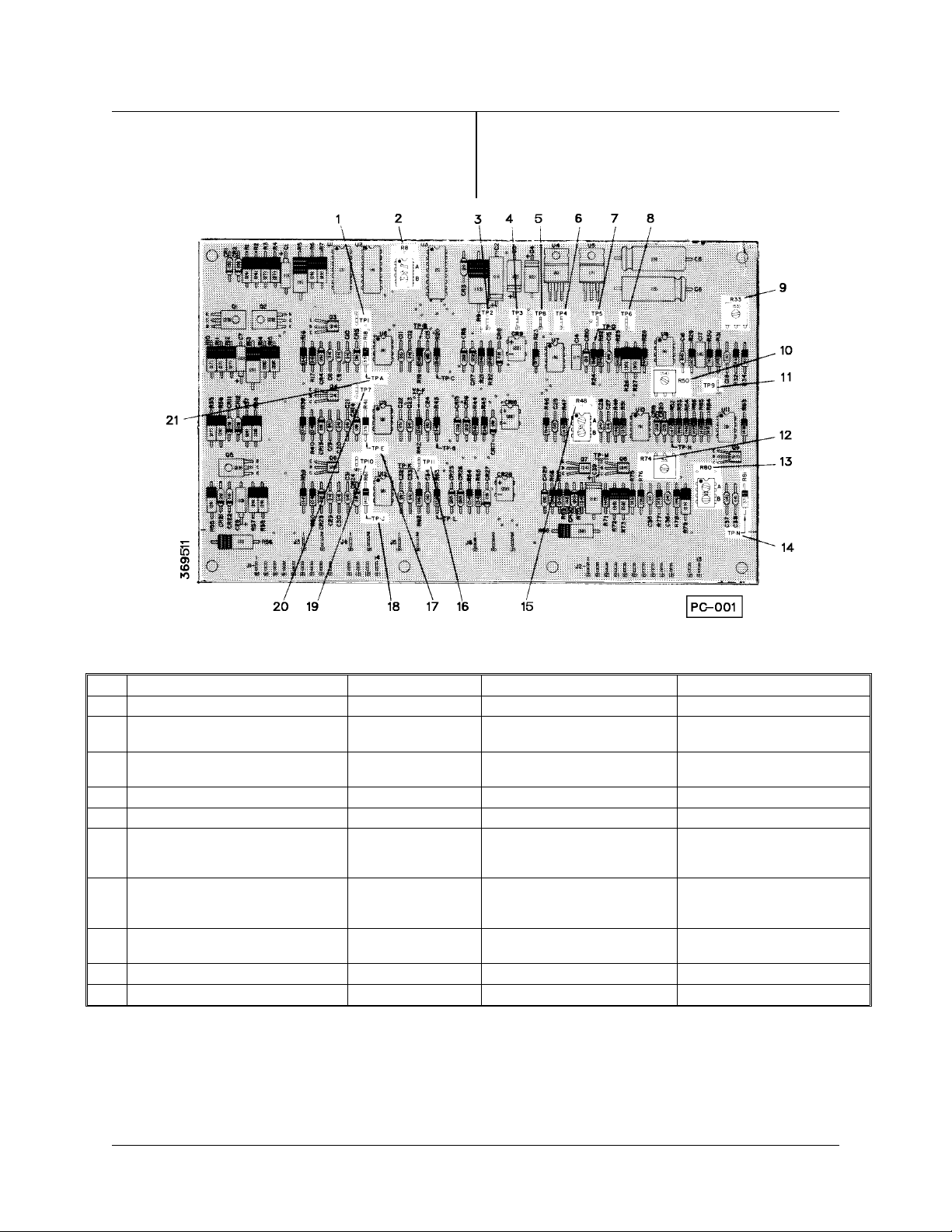
Detailed Setting and Troubleshooting of
Printed Circuit (PC) Board (369511)
Test Points – There are several test points on the
PC Board which will aid in determining if the defect
430429-238
TROUBLESHOOTING
is in the board. First, be certain that all wiring to the
board is in good shape and the input (X1-X3) leads
are in place. The following voltage checks (Table
7-2) should be made in sequence.
Figure 7-5 Printed Circuit Board
Test Test Points Voltage Conditions Remarks
1 (6) TP4 to TP6 or 11 (8 or 16) +15 V DC ± 5% Open-circuit Checks output of regulator
2 (7) TP5 to TP6 or 11 (8 or 16) –15 V DC ± 5% Open-circuit Χηεχκσ ουτπυτ οφ
ρεγυλατορ
3 (3) TP2 to TP6 or 11 (8 or 16) +22 V DC ±10% Open-circuit Checks solid state contactor
control
4 (4)TP3 to TP6or 11 (8 or16) +9.1 V DC ±10% Open-circuit Checks reference voltage
5 (12) TPN to TP6 or 11 (8 or 16) –10 V DC Open-circuit Checks reference voltage
6 (21) TPA to TP6 or 11 (8 or 16)
(17) TPE to TP6 or 11 (8 or 16)
(18) TPJ to TP6 or 11 (8 or 16)
7 (1) TP1 to TP6 or 11 (8 or 16)
(20) TP7 to TP6 or 11 (8 or 16)
(19) TP10 to TP6 or 11 (8 or 16)
2.7 V DC ± 10%
2.7 V DC ± 10%
2.7 V DC ± 10%
2.5 V DC ± 10%
2.5 V DC ± 10%
2.5 V DC ± 10%
Current control set @ 50%
Current control set @ 50%
Open-circuit
Open-circuit
Open-circuit
Open-circuit
8 (5)TP8 toTP6or11 (8 or 16) 1.6 V DC ± 10% Minimum output
High range
-Checks timer operation
Checks timer operation
Checks summing Op.
Amp.
9 (11) TP9 to TP6 or 11 (8 or 16) 0.4 V DC ± 10% Short circuit Checks feedback circuit
10 (11) TP9 to TP6 or 11 (8 or 16) 0 V DC Open-circuit Checks zero calibration
NOTE: Locate numbers in parens ( ) on PC Board by callout numbers. Itwill be necessary to scrapevarnish
from component lead test points and post test points to get a voltmeter reading.If any of the above tests fail,
there is a high probability of a defective P.C. Board.
Table 7-6
December 1, 1997 Revised 7-7
Page 30

430429-238
TROUBLESHOOTING
CAUTION: The open-circuit voltage is
set on the PC Board. This setting is
sensitive to line voltage.Do not connect
a machine to a line in which the voltage
varies more than ±10% of nominal line
voltage. For example, on a 460-volt line,
the operating voltage is 414to 504 volts.
POTENTIOMETER SETTINGS — The following
is a brief descriptionofthe potentiometers and what
parameters they control. Callout numbers from Figure 7-5 are in parenthesis ( ).
1.PotR80B (13) — Adjusts the output offeedback
amplifier U8 and eliminates offset voltage values.
2. Pot R33 (9) — Adjusts the 10 V DC reference
voltage.
3. Pots R8A and R8B (2) — Adjusts the phase
balance output of the SCR rectifier.
4. Pot R48A (15) — Adjusts the maximum open-
circuit voltage.
5. Pot R48B (15) — Adjusts the voltage point at
which the current begins increasing in the arc force
circuit.
NOTE: All potentiometer operating values
are preset at the factory, and normally
should not have to be reset in the field. If a
needarisesthatwould indicatetheneed for
field adjustments, please contact the factory.
6. Pot R74 (12) — Adjusts the maximum short
circuit current in the arc force circuit.
7. Pot R80A (13) — Adjusts the minimum output
current.
8. Pot R50 (10) — Adjusts the maximum output
current.
7-8 December 1, 1997 Revised
Page 31

PARTS LIST
430429-238
PARTS LIST
Equipment Identification
All identification numbers as described in the Introductionchaptermustbefurnishedwhenordering
partsormakinginquiries.Thisinformationisusually
found on the nameplate attachedto the equipment.
Be sure to include any dash numbers following the
Specification or Assembly numbers.
How To Use This Parts List
The Parts List is a combination of an illustration
(Figure Number) and a corresponding list of parts
which contains a breakdown of the equipment into
assemblies, subassemblies, and detail parts. All
partsofthe equipmentarelistedexcept forcommercially available hardware, bulk items such as wire,
cable, sleeving, tubing, etc., and permanently attached items which aresoldered,riveted,or welded
SPECIFICATION NUMBER APPLICATION CODE
to another part. The part descriptions may be
indented to show part relationships.
Todeterminethepart number, description,quantity,orapplicationof an item, simplylocatetheitem
in question from the illustration and refer to that
item number in the corresponding Parts List.
An“ApplicationCode”isused to distinguish parts
that are applicable only to certain Specifications
and/or Assemblies. Thiscode is foundin the rightmostcolumnof thePartsList.Ifan itemintheParts
ListappliestoallSpecificationsorAssemblies,the
word “ALL” will be intheApplication Code column.
Refer to the following list to determine the appropriate Application Codes for the Specifications or
Assemblies covered by this manual. If only the
assemblyor specification number is listed, the use
of an Application Code does not apply to this
manual.
6031A-3 A
6032A-3 B
6036A-3 C
6037A-3 D
6041A-4 E
6042A-3 F
6046A-3 G
6047A-3 H
6036B-3 J
December 1, 1997 Revised 8-1
Page 32
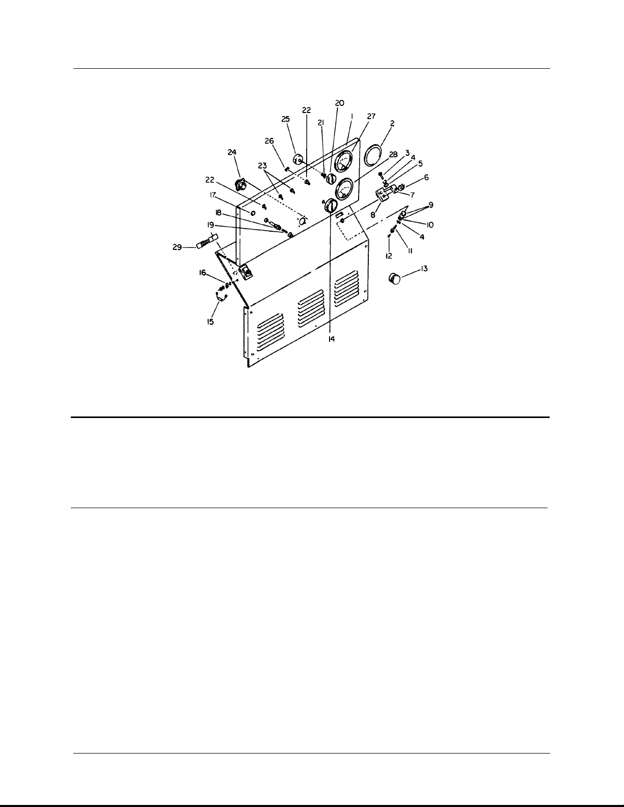
430429-238
PARTS LIST
Figure 8-1 Control Panel
Parts List for Figure 8-1
Item Part Description Qty Application
No Number per Code
Assy
369685-11 Panel - Control, Front Assy. 1 AB
369685-12 Panel - Control, Front Assy. 1 CD
369685-13 Panel - Control, Front Assy. 1 EF
369685-15 Panel - Control, Front Assy. 1 J
200906-3 Panel - Control, Front Assy. 1 GH
1 369684-5 Panel - Control 1 AB
369684-6 Panel - Control 1 CD
369684-7 Panel - Control 1 EF
369684-9 Panel - Control 1 J
200854-2 Panel - Control 1 GH
2 AW-113-3 . Cover - Meter Hole 2 ABCD
EFGH
AW-113-9 . Cover - Meter Hole 2 J
3 No Number . Screw - 1/2-13 x 1-1/4, HHC, ST. 2 All
4 No Number . Washer - 1/2, LK, ST. 4 All
8-2 December 1, 1997 Revised
Page 33

430429-238
PARTS LIST
Parts List for Figure 8-1
Item Part Description Qty Application
No Number per Code
Assy
5 No Number . Washer - 1/2, FL, ST. 2 All
6 400614-1 . Nut - 1/2-13, Hex, FLG. ST. 2 All
7 5CW-974 . Bus - Stud, Cable 2 All
8 5CW-975 . Bushing - Insulator, Stud 2 All
9 5CW-976A . Washer - Insulator 4 All
10 No Number . Washer - 1/2, FL. ST. 2 All
11 351505 . Screw - 1/2-13 x1-3/4HHC(Drilled for Item12) 2 All
12 No Number . Screw - #6-32 x 3/16, Rd. Hd. MH. ST. 2 All
13 903914-1 . Cap - Connector 1 All
14 408850-5 . Knob - Control 1 All
15 368705-8 . Capacitor - W/Lead & Term. 2 All
16 402900 . Terminal - Q.C. Tab, Male 2 All
17 402421-3 . Light - Pilot, Amber 1 All
18 402658 . Fuseholder 1 All
19 W-11166-10 . Fuse - 3 Amp AGC 1 All
20 406806-3 . Knob - Control 1 All
21 200930 . Stop - Knob 1 All
369686 . Harness - Wire Assembly 1 ABCD
EFJ
200911 . Harness - Wire Assembly 1 GH
22 405365-1 . . Switch - Toggle, SPST 2 All
23 405365-2 . . Switch - Toggle, SPDT 2 All
24 400758 . . Receptacle - 6 Pin, Amphenol 1 All
25 401428-8 . . Potentiometer - 2 Watt, 5K 2 All
26 367703-1 . . Resistor - 1/2 Watt, Assembly 1 All
367845-1 Kit - Meter (Optional) 1 ABCDJ
367845-2 Kit - Meter (Optional) 1 EFGH
27 400641-6 . Ammeter - DC, Single Scale 1 ABCDJ
400641-8 . Ammeter - DC, Single Scale 1 EFGH
28 400642-4 . Voltmeter - DC, Single Scale 1 All
29 CW-1142A . Shunt 1 ABCDJ
4DW-77 . Shunt 1 EFGH
December 1, 1997 Revised 8-3
Page 34
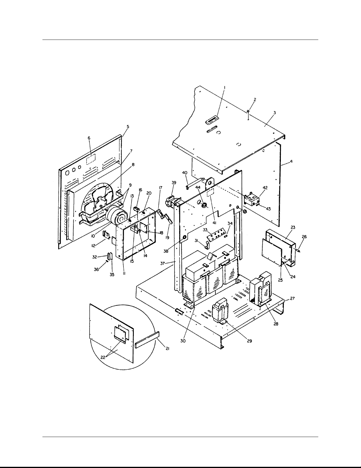
430429-238
PARTS LIST
Figure 8-2 Base and Lifting Yoke Group
8-4 December 1, 1997 Revised
Page 35

430429-238
PARTS LIST
Parts List for Figure 8-2
Item Part Description Qty Application
No Number per Code
Assy
1 12CW-2170 Grommet - Top 1 All
2 403091-4 Plug - Hole, Plastic 8 All
3 369652 Panel - Top 1 ABCDEF
369652-1 Panel - Top 1 J
200791-1 Panel - Top 1 GH
4 369651 Panel - Side, Left and Right 2 ABCDEF
369651-1 Panel - Side, Left and Right 2 J
200789 Panel - Side, Left and Right 2 GH
5 369683 Panel - Rear 1 ABCDEF
369683-1 Panel - Rear 1 J
200793 Panel - Rear 1 GH
6 407961A-1 Nameplate 1 All
7 369650 Shroud - Fan 1 ABCD
EFGH
369650-1 Shroud - Fan 1 J
8 8RT-609 Blade - Fan 1 All
9 369640 Bracket - Motor 2 ABCD
EFGH
369640-1 Bracket - Motor 2 J
10 12TW-595-1 Motor - Fan 1 All
369638-11 Rectifier - Output Assembly 1 AB
369638-12 Rectifier - Output Assembly 1 CDJ
369638-3 Rectifier - Output Assembly 1 EF
369638-10 Rectifier - Output Assembly 1 GH
11 369639 . Heat Sink - Rect. 1 All
12 367634A-3 . Suppressor - Surge, Assembly 2 All
— 405157 . Label - Fuse 1 All
13 404044-1 . Thermostat - Overload 1 ABCDJ
404044-3 . Thermostat - Overload 1 EF
404044-4 . Thermostat - Overload 1 GH
14 369642 . Heat Sink - SCR 6 All
15 405139 . Rectifier - Silicon Cont. 6 All
16 405140-1 . Clamp - Mounting 6 All
— 16DA-954-12 . Pin - Spring 6 All
17 201072 . Shunt 1 AB
201073 . Shunt 1 CDJ
367732 . Shunt 1 EF
367733 . Shunt 1 GH
18 369641 . Insulator - Mtg. Rect. 2 All
December 1, 1997 Revised 8-5
Page 36

430429-238
PARTS LIST
Parts List for Figure 8-2
Item Part Description Qty Application
No Number per Code
Assy
19 369703 Bar - Bus, Output Term. to Shunt 1 ABCD
EFJ
W-9234-55 Cable - Terminal to Shunt 2 GH
20 200155A Thermostat - Fan Turn On (Optional) 1 All
— Not Illustrated
21 200157A Kit - Cover, OSHA (Optional) 1 ABCDEFJ
201019 Kit - Cover, OSHA (Optional) 1 GH
22 369826 Kit - Side Panel W/Access Door (Optional) 1 ABCDEF
— 201020 Kit - Side Panel W/Access Door (Optional) 1 GH
369669-2 Panel - PC Board, Assembly 1 ABCDEF
369669-10 Panel - PC Board, Assembly 1 J
200890-1 Panel - PC Board, Assembly 1 GH
23 369670 . Panel - PC Board 1 ABCDEF
369670-1 . Panel - PC Board 1 J
200891 . Panel - PC Board 1 GH
24 404915-1 . Spacer - PC Board 6 All
25 369511 . Board - PC Assembly 1 All
26 200114 Spacer - PC Board 1 All
27 369653 Base 1 ABCDEF
369653-1 Base 1 J
369672 Transformer - Interphase 1 ABCD
368084-5 Transformer - Interphase 1 EF
368084-6 Transformer - Interphase 1 GH
29 367723-2 Reactor - Filter 1 AB
367696-2 Reactor - Filter 1 CD
367718-2 Reactor - Filter 1 EF
367718-4 Reactor - Filter 1 GH
30 200290 Transformer - Power Assembly 1 A
200291 Transformer - Power Assembly 1 B
200295 Transformer - Power Assembly 1 C
200296 Transformer - Power Assembly 1 D
200300 Transformer - Power Assembly 1 E
200301 Transformer - Power Assembly 1 F
200926 Transformer - Power Assembly 1 G
200927 Transformer - Power Assembly 1 H
31 200770 . Brace - V.C. Board 2 ABCDEF
200899 . Brace - V.C. Board 2 GH
32 405129-1 . Block - Fuse 1 All
— Not Illustrated
8-6 December 1, 1997 Revised
Page 37

430429-238
PARTS LIST
Parts List for Figure 8-2
Item Part Description Qty Application
No Number per Code
Assy
33 367229-9 . Board - Voltage Changeover 1 ACEG
367229-8 . Board - Voltage Changeover 1 BDFH
34 CW-811 Link - Voltage Changeover 6 ACEGH
CW-811 Link - Voltage Changeover 3 BDF
35 367579 Insulator - Fuse Block 1 All
36 W-11166-9 Fuse - 1 Amp 6 All
369630-2 Yoke - Lifting Assembly 1 ABCD
369630-6 Yoke - Lifting Assembly 1 EF
369630-11 Yoke - Lifting Assembly 1 J
200909-2 Yoke - Lifting Assembly 1 GH
37 369631 . Yoke - Lifting Assembly 1 ABCDEF
369631-1 . Yoke - Lifting Assembly 1 J
200886 . Yoke - Lifting Assembly 1 GH
38 405362-1 . Bushing - Snap 1 ABCDEFJ
— 830116 . Label - Frame Ground 1 ABCDEFJ
39 405479 . Contactor 1 ABCDJ
405402 . Contactor 1 EFGH
40 406358-2 . Resistor - 50 Ohms 1 All
41 405793 . Label - Warning 1 All
42 406392-2 . Transformer - Control 1 All
43 W-11166-11 . Fuse - .5 Amp 1 All
— 406484 . Label - Fuse 1 All
44 405362-2 . Bushing - Snap 1 All
— 204036 Label - Precautionary 1 All
— Not Illustrated
December 1, 1997 Revised 8-7
Page 38

430429-238
PARTS LIST
This page intentionally left blank.
8-8 December 1, 1997 Revised
Page 39

DIAGRAMS
• Note the Model and Assembly numbers shown on the equipment nameplate.
• Locate these numbers in the table below.
• Use only those diagrams and instructions that are applicable.
MODEL
NUMBER
SPECIFICATION
NUMBER
CONNECTION
DIAGRAM
VOLTAGE
CHANGEOVER
DIAGRAM
430429-238
DIAGRAMS
OUTLINE
DIMENSION
MA-3
MA-4
MA-5
MA-7
6031A-3
6032A-3
6036A-3
6036B-3
6037A-3
6041A-4
6042A-3
6046A-3
6047A-3
369704
369704
369704
369704
369704
369704
369704
369704
369704
200032
200033
200032
200032
200033
200032
200033
200032
200033
369707-1
369707-1
369707-1
369707-1
369707-1
369707-1
369707-1
369707-2
369707-2
December 1, 1997 Revised
Page 40
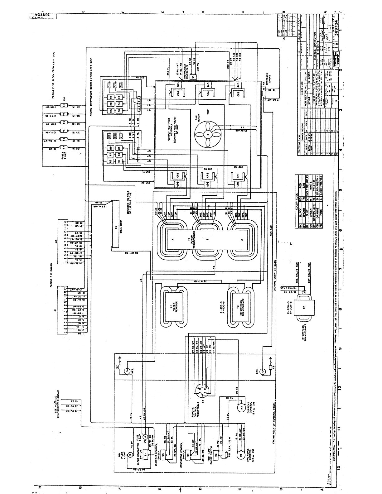
Page 41
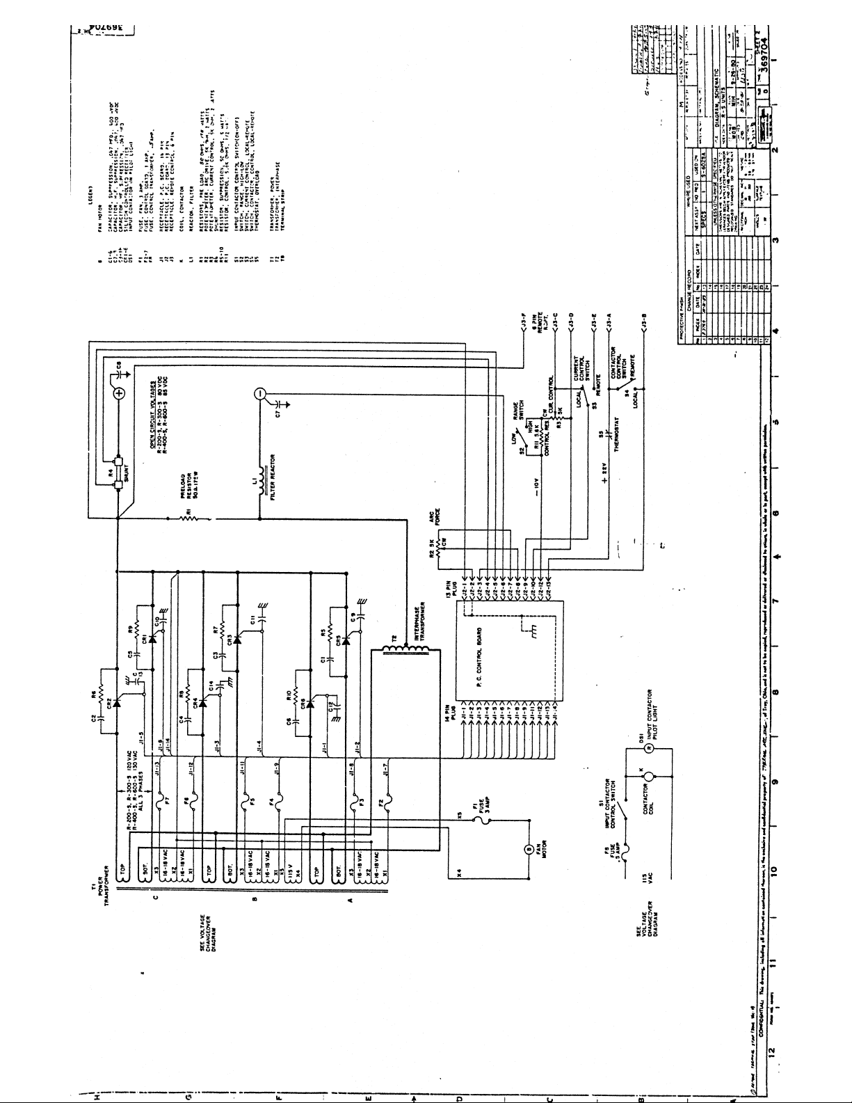
Page 42
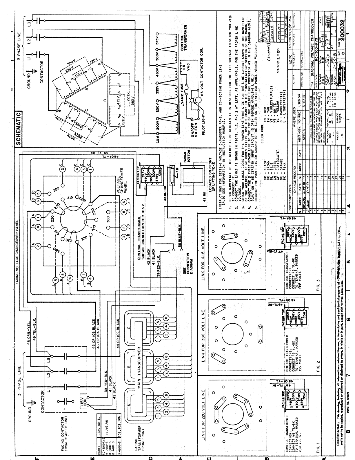
Page 43
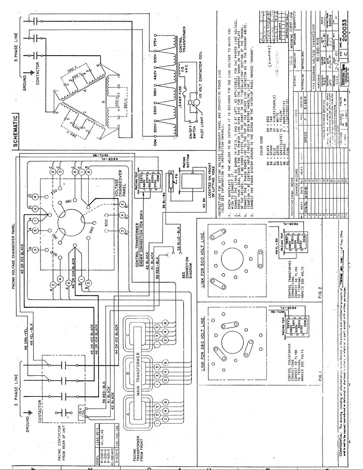
Page 44
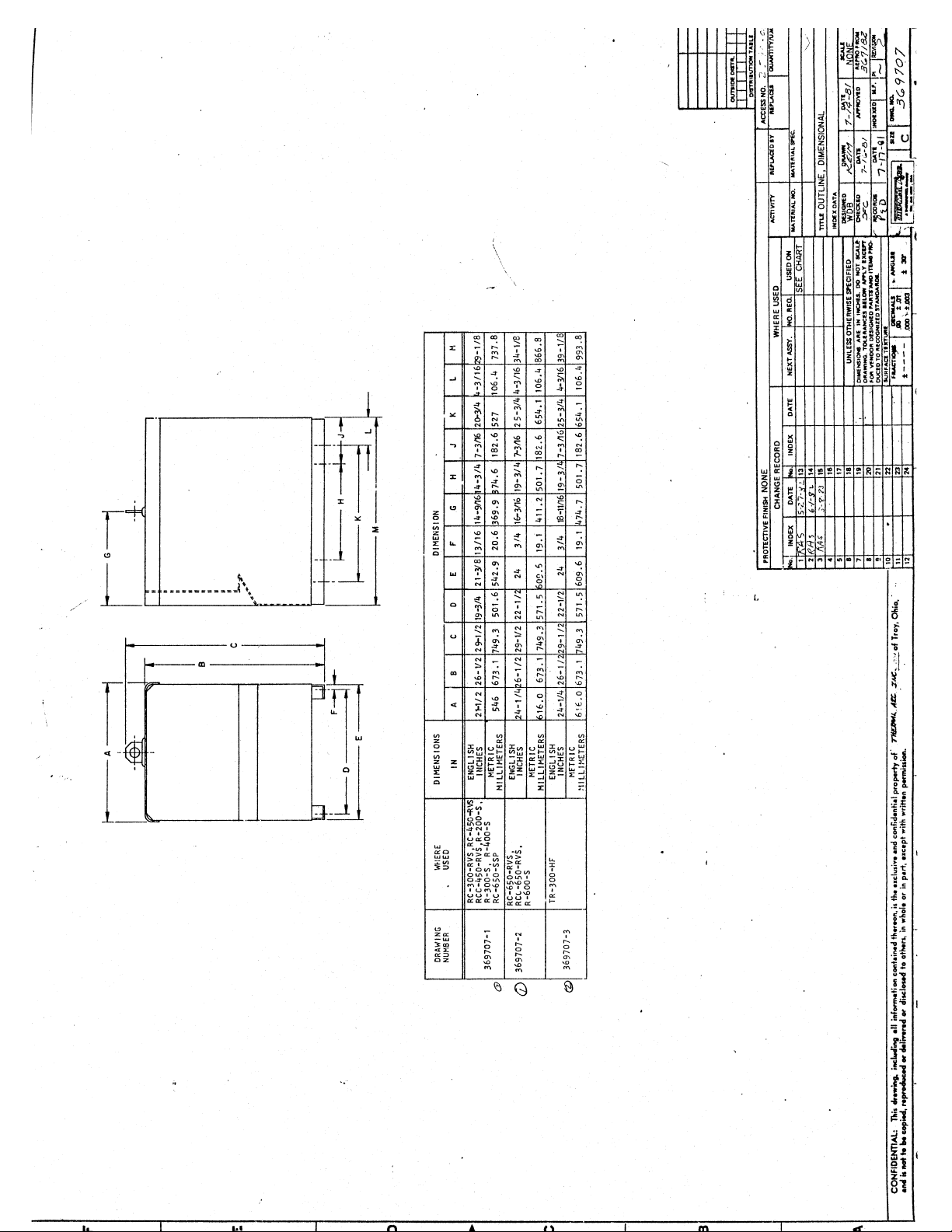
Page 45

STATEMENT OF WARRANTY
LIMITED WARRANTY:Thermal Arc®, Inc., A ThermadyneCompany, warrants that its products willbefree of defects in workmanship
ormaterial.Should anyfailure to conformto this warrantyappear within the timeperiod applicable tothe Thermal Arc productsas stated
below, Thermal Arc shall, upon notification thereof and substantiation that the product has been stored, installed, operated, and
maintained in accordancewith Thermal Arc’sspecifications,instructions, recommendationsandrecognized standard industry practice,
and not subject to misuse, repair, neglect, alteration, or accident, correct such defects by suitable repair or replacement, at Thermal
Arc’s sole option, of any components or parts of the product determined by Thermal Arc to be defective.
THERMAL ARC MAKES NO OTHER WARRANTY, EXPRESS OR IMPLIED. THIS WARRANTY IS EXCLUSIVE AND IN LIEU OF
ALL OTHERS, INCLUDING, BUT NOT LIMITED TO ANY WARRANTY OF MERCHANTABILITY OR FITNESS FOR ANY
PARTICULAR PURPOSE.
LIMITATION OF LIABILITY: Thermal Arc shall not under any circumstancesbe liable for special or consequential damages, such as,
but not limited to, damage or loss of purchased or replacement goods, or claims of customers of distributor (hereinafter “Purchaser”)
for service interruption.The remedies of the Purchaser set forth herein are exclusive and the liabilityof Thermal Arcwith respect to any
contract, or anything done in connection therewith such as the performance or breach thereof, or from the manufacture, sale, delivery,
resale, or use of any goods covered by or furnished by Thermal Arc whether arising out of contract, negligence, strike tort, or under
any warranty, or otherwise, shall not, except as expressly provided herein, exceed the price of the goods upon which such liability is
based. No employee, agent, or representative of Thermal Arc is authorized to change this warranty in any way or grant any other
warranty.
PURCHASER’SRIGHTS UNDER THISWARRANTY AREVOID IFREPLACEMENTPARTS ORACCESSORIESARE USEDWHICH
IN THERMAL ARC’S SOLE JUDGMENT MAY IMPAIR THE SAFETY OR PERFORMANCE OF ANY THERMAL ARC PRODUCT.
PURCHASER’S RIGHTS UNDER THIS WARRANTY ARE VOID IF THE PRODUCT IS SOLD TO PURCHASER BY
NON-AUTHORIZED PERSONS.
Except with regards to the products listed below, this warranty shall remain effective three (3) years from the date Thermal Arc’s
authorized distributor delivers the product to Purchaser, but in no event more than (4) years from the date Thermal Arc delivers the
product to the authorized distributor.
Shorter warranty periods apply to the products listed below. On these products, the warranty is effective for the time stated below
beginning on the date that the authorized distributor delivers the products to the Purchaser. Notwithstanding the foregoing, in no event
shall the warranty period extend more than the time stated plus one year from the date Thermal Arc delivered the product to the
authorized distributor.
ALL OTHER P-WEE, PRO-LITE
POWER SUPPLIES POWER SUPPLIES PRO-PLUS, PRO-WAVE LABOR
MAIN POWER MAGNETICS (STATIC & ROTATING) 3 YEARS 2 YEARS 1 YEAR
ORIGINAL MAIN POWER RECTIFIER 3 YEARS 2 YEARS 1 YEAR
CONTROL PC BOARD 3 YEARS 2 YEARS 1 YEAR
ALLOTHERCIRCUITSANDCOMPONENTSINCLUDING 1 YEAR 1 YEAR 1 YEAR
BUT NOT LIMITED TO, CONTACTORS, RELAYS,
SOLENOID, PUMPS, POWER SWITCHING SEMI-CONDUCTORS
ENGINES: ENGINES ARE NOT WARRANTED BY THERMAL ARC, ALTHOUGH MOST ARE WARRANTED BY THE ENGINE
MANUFACTURER. SEE THE ENGINE MANUFACTURES WARRANTY FOR DETAILS
CONSOLES, CONTROL EQUIPMENT, HEAT 1 YEAR 1 YEAR 1 YEAR
EXCHANGES, AND ACCESSORY EQUIPMENT
TORCH AND LEADS 180 DAYS 180 DAYS 180 DAYS
REPAIR/REPLACEMENT PARTS 90 DAYS 90 DAYS 90 DAYS
Warranty repairsor replacement claims underthis limited warranty must besubmitted to Thermal Arcbyan authorized Thermal Arc®repair
facility within thirty (30) days of the repair. No transportation costs of any kind will be paid under this warranty. Transportation charges to
sendproducts toan authorizedwarrantyrepairfacility shallbe theresponsibilityof thecustomer. Allreturned goodsshall beat thecustomer’s
risk and expense. This warrantysupersedes all previous Thermal Arc warranties.
.
Thermal Arc®is a Registered Trademark of Thermadyne Industries Inc.
Thermal Arc Inc. Effective January 4, 1999
Troy, Ohio 45373 830538
Page 46

 Loading...