


INSTALLATION INSTRUCTIONS
ENGINE PROTECTION SHUTDOWN KIT
For the Following Specs:
494170-1
•
494170-3
•
OWNER’S MANUAL Number 430429-080 (Rev - AA)
Revised March 13, 2000
IMPORTANT: Readtheseinstructionsbeforeinstalling,operating, or servicing this system.
THERMAL ARC INC., TROY, OHIO 45373-1085, U.S.A.

ARC WELDING SAFETY INSTRUCTIONS AND WARNINGS
Instruction 830001
ARC WELDING SAFETY INSTRUCTIONS AND WARNINGS
ARC WELDING can be hazardous.
PROTECT YOURSELF AND OTHERS FROM POSSIBLE SERIOUS INJURY OR DEATH. KEEP CHILDREN AWAY. PACEMAKER
WEARERSKEEPAWAY UNTILCONSULTINGYOUR DOCTOR.DONOT LOSETHESEINSTRUCTIONS. READOPERATING/INSTRUCTION MANUAL BEFORE INSTALLING, OPERATING OR SERVICING THIS EQUIPMENT.
Welding products and welding processes can cause serious injury or death, or damage to other equipment or property, if the operator does
not strictly observe all safety rules and take precautionary actions.
Safe practices have developed from past experience in the use of welding and cutting. These practices must be learned through study and
trainingbeforeusingthis equipment. Anyone not havingextensivetraining in welding and cuttingpracticesshould not attempt to weld.Certain
of the practices apply to equipment connected to power lines; other practices apply to engine driven equipment.
Safe practices are outlined in the American National Standard Z49.1 entitled:
other guides to what you should learn before operating this equipment are listed at the end of these safety precautions.
HAVE ALL INSTALLATION, OPERATION, MAINTENANCE, AND REPAIR WORK PERFORMED ONLY BY QUALIFIED PEOPLE.
ELECTRIC SHOCK can kill.
Touchingliveelectrical partscancause fatal shocks
or severe burns. The electrode and work circuit is
electricallylivewhenevertheoutputison. The input
power circuit and machine internal circuits are also
livewhen poweris on.In semiautomaticorautomatic
wire welding, the wire, wire reel, drive roll housing,
and all metal parts touching the welding wire are
electrically live. Incorrectly installed or improperly
grounded equipment is a hazard.
1. Do not touch live electrical parts.
2. Wear dry, hole-free insulating gloves and body protection.
3. Insulate yourselffromwork and ground using dryinsulatingmats
or covers.
4. Disconnect input power or stop engine before installing or servicing this equipment. Lock input power disconnect switch open,
or remove line fuses so power cannot be turned on accidentally.
5. Properly install and ground this equipment according to its
Owner’s Manual and national, state, and local codes.
SAFETY IN WELDING AND CUTTING. This publication and
6. Turn off all equipment when not in use. Disconnect power to
equipment if it will be left unattended or out of service.
7. Use fully insulated electrode holders. Never dip holder in water
to cool it or lay it down on the ground or the work surface.Donot
touch holders connected to two welding machines at the same
time or touch other people with the holder or electrode.
8. Do notuse worn, damaged,undersized,or poorlysplicedcables.
9. Do not wrap cables around your body.
10. Ground the workpiece to a good electrical (earth) ground.
11. Do not touch electrode while in contact with the work (ground)
circuit.
12. Useonlywell-maintained equipment.Repair orreplacedamaged
parts at once.
13. In confined spaces or damp locations, do not use a welder with
AC output unless it is equipped with a voltage reducer. Use
equipment with DC output.
14. Wear a safety harness to prevent falling if working above floor
level.
15. Keep all panels and covers securely in place.
ARC RAYS can burn eyes and skin;
NOISE can damage hearing.
Arc rays from the welding process produce intense
heat and strong ultraviolet rays that can burn eyes
and skin. Noise from some processes can damage
hearing.
Eye protection filter shade selector for welding or cutting (goggles or helmet), from AWS A6.2-73.
Welding or Cutting
Operation
Torch soldering
Torch brazing
Oxygen cutting
Light
Medium
Heavy
Gas welding
Light
Medium
Heavy
Shielded metal-arc welding
(stick) electrodes
Electrode Size
Metal Thickness
or Welding Current
—
—
Under 1 in., 25 mm
1 to 6 in., 25-150 mm
Over 6 in., 150 mm
Under 1/8 in., 3 mm
1/8 to 1/2 in., 3-12 mm
Over 1/2 in., 12 mm
Under 5/32 in., 4 mm
5/32 to 1/4 in., 4 to 6.4 mm
Over 1/4 in., 6.4 mm
Filter
Shade
No.
2
3or4
3or4
4or5
5or6
4or5
5or6
6or8
10
12
14
1. Wear a welding helmet fitted with a proper shade of filter (see
ANSI Z49.1 listed in Safety Standards) to protect your face and
eyes when welding or watching.
2. Wear approved safety glasses. Side shields recommended.
3. Use protective screens or barriers to protect others from flash
and glare; warn others not to watch the arc.
4. Wear protective clothing made from durable, flame-resistant
material (wool and leather) and foot protection.
5. Use approved ear plugs or ear muffs if noise level is high.
Welding or Cutting
Operation
Gas metal-arc welding (MIG)
Non-ferrous base metal
Ferrous base metal
Gastungstenarcwelding (TIG)
Atomic hydrogen welding
Carbon arc welding
Plasma arc welding
Carbon arc air gouging
Light
Heavy
Plasma arc cutting
Light
Medium
Heavy
Electrode Size
Metal Thickness
or Welding Current
All
All
All
All
All
All
Under 300 Amp
300 to 400 Amp
Over 400 Amp
May 8, 1996 2-1
Filter
Shade
No.
11
12
12
12
12
12
12
14
9
12
14

ARC WELDING SAFETY INSTRUCTIONS AND WARNINGS
Instruction 830001
FUMES AND GASES can be hazardous
to your health.
Weldingproducesfumesandgases.Breathingthese
fumes and gases can be hazardous to your health.
1. Keep your head out of the fumes. Do not breath the fumes.
2. If inside, ventilate the area and/or use exhaust at the arc to
remove welding fumes and gases.
3. If ventilation is poor, use an approved air-supplied respirator.
WELDING can cause fire or explosion.
Sparks and spatter fly off from the welding arc. The
flying sparks and hot metal, weld spatter, hot workpiece, and hot equipment cancausefiresand burns.
Accidental contact of electrode or welding wire to
metal objects can cause sparks, overheating, or fire.
1. Protect yourself and others from flying sparks and hot metal.
2. Do not weld where flying sparks can strike flammable material.
3. Remove all flammables within 35 ft (10.7 m) of the welding arc.
If this is not possible, tightly cover them with approved covers.
4. Be alert that welding sparks and hot materials from welding can
easily go through small cracks and openings to adjacent areas.
4. Read the Material Safety Data Sheets (MSDSs) and the manufacturer’s instruction for metals, consumables, coatings, and
cleaners.
5. Work in a confined space only if it is well ventilated, or while
wearing an air-supplied respirator. Shielding gases used for
welding can displace air causing injury or death. Be sure the
breathing air is safe.
6. Do not weld in locations near degreasing, cleaning, or spraying
operations. The heat and raysofthearccanreactwithvapors to
form highly toxic and irritating gases.
7. Do not weld on coated metals, such as galvanized, lead, or
cadmium plated steel, unless the coating is removed from the
weld area, the area is well ventilated, and if necessary, while
wearing an air-supplied respirator. The coatings and any metals
containing these elements can give off toxic fumes if welded.
5. Watch for fire, and keep a fire extinguisher nearby.
6. Be aware that welding on a ceiling, floor, bulkhead, or partition
can cause fire on the hidden side.
7. Do not weld on closed containers such as tanks or drums.
8. Connect work cable to the work as close to the welding area as
practical to prevent welding current from traveling long, possibly
unknown paths and causing electric shock and fire hazards.
9. Do not use welder to thaw frozen pipes.
10. Remove stick electrode from holder or cut off welding wire at
contact tip when not in use.
11. Wear oil-free protective garments such as leather gloves, heavy
shirt, cuffless trousers, high shoes, and a cap.
FLYING SPARKS AND HOT METAL can
cause injury.
Chipping and grinding cause flying metal. As welds
cool, they can throw off slag.
CYLINDERS can explode if damaged.
Shielding gas cylinderscontaingasunderhighpressure. If damaged, a cylinder can explode. Since gas
cylinders are normally part of the welding process,
be sure to treat them carefully.
1. Protectcompressed gascylindersfromexcessiveheat,mechanical shocks, and arcs.
2. Install and secure cylinders in an upright position by chaining
themtoastationarysupportorequipment cylinderracktoprevent
falling or tipping.
ENGINE EXHAUST GASES can kill.
Engines produce harmful exhaust gases.
1. Wear approved face shield or safety goggles. Side shields recommended.
2. Wear proper body protection to protect skin.
3. Keep cylindersawayfrom any welding orotherelectrical circuits.
4. Never allow a welding electrode to touch any cylinder.
5. Use only correct shielding gas cylinders, regulators, hoses, and
fittings designed for the specific application; maintain them and
associated parts in good condition.
6. Turn face away from valve outlet when opening cylinder valve.
7. Keep protective cap in place over valve except when cylinder is
in use or connected for use.
8. Read and follow instructionsoncompressedgas cylinders, associated equipment, and CGA publication P-1 listed in Safety
Standards.
ENGINES can be hazardous.
1. Use equipment outside in open, well-ventilated areas.
2. If used in a closed area, vent engine exhaust outside and away
from any building air intakes.
2-2 May 8, 1996

ARC WELDING SAFETY INSTRUCTIONS AND WARNINGS
Instruction 830001
ENGINE FUEL can cause fire or
explosion.
Engine fuel is highly flammable.
1. Stop engine before checking or adding fuel.
MOVING PARTS can cause injury.
Moving parts,suchasfans, rotors, and belts cancut
fingers and hands and catch loose clothing.
1. Keep all doors, panels, covers, and guards closed and securely
in place.
2. Stop engine before installing or connecting unit.
SPARKS can cause BATTERY GASES
TO EXPLODE; BATTERY ACID can
burn eyes and skin.
Batteriescontain acidandgenerateexplosivegases.
STEAM AND PRESSURIZED HOT
COOLANT can burn face, eyes, and
skin.
The coolantinthe radiator can beveryhot and under
pressure.
WARNING: This product, when used for welding or cutting, produces fumes or gases which contain chemicals known to the State
of California to cause birth defects and, in some cases, cancer. (California Health & Safety Code Sec. 25249.5 et seq.)
NOTE: Considerations About Welding And The Effects Of Low Frequency Electric And Magnetic Fields
The following is a quotation from the General Conclusions Section of the U.S. Congress, Office of Technology Assessment,
of Power Frequency Electric& Magnetic Fields — Background Paper, OTA-BP-E-63 (Washington, DC: U.S. Government Printing Office, May
1989): “... there is now a very large volume of scientific findings based on experiments at the cellular level and from studies with animals and
people which clearly establish that low frequency magnetic fields can interact with, and produce changes in, biological systems. While most of
this work is of very high quality, the results are complex. Current scientific understanding does not yet allow us to interpret the evidence in a
single coherent framework. Even more frustrating, it does not yet allow us to draw definite conclusions about questions of possible risk or to
offer clear science-based advice on strategies to minimize or avoid potential risks.”
To reduce magnetic fields in the workplace, use the following procedures:
1. Keep cables close together by twisting or taping them.
2. Arrange cables to one side and away from the operator.
2. Do not addfuelwhile smokingorif unitisnear anysparksor open
flames.
3. Allow engine to cool before fueling. If possible, check and add
fuel to cold engine before beginning job.
4. Do not overfill tank — allow room for fuel to expand.
5. Do not spillfuel.Iffuelisspilled,clean up before starting engine.
3. Have only qualified people remove guards or covers for mainte-
nance and troubleshooting as necessary.
4. To prevent accidentalstartingduring servicing, disconnectnega-
tive (-) battery cable from battery.
5. Keep hands, hair, loose clothing, and tools away from moving
parts.
6. Reinstall panels or guards and close doors when servicing is
finished and before starting engine.
1. Always wear a face shield when working on a battery.
2. Stop engine before disconnecting or connecting battery cables.
3. Do not allow tools to cause sparks when working on a battery.
4. Do not use welder to charge batteries or jump start vehicles.
5. Observe correct polarity (+ and –) on batteries.
1. Do not remove radiator cap when engine is hot. Allow engine to
cool.
2. Wear gloves and put a rag over cap area when removing cap.
3. Allow pressure to escape before completely removing cap.
Biological Effects
3. Do not coil or drape cables around the body.
4. Keep welding power source and cables as far away from body as
practical.
About Pacemakers:
The above procedures are among those also normally recommended for pacemaker wearers. Consult your doctor for complete information.
PRINCIPAL SAFETY STANDARDS
Safety inWeldingandCutting,ANSI Standard Z49.1, from American
Welding Society, 550 N.W. LeJeune Rd., Miami, FL 33126.
SafetyandHealthStandards, OSHA 29 CFR1910,fromSuperintendent of Documents, U.S. Government Printing Office, Washington,
D.C. 20402.
Recommended Safe Practices for the Preparation for Welding and
CuttingofContainersThatHaveHeldHazardousSubstances,American Welding Society Standard AWS F4.1, from American Welding
Society, 550 N.W. LeJeune Rd., Miami, FL 33126.
National Electrical Code, NFPA Standard 70, from National Fire
Protection Association, Batterymarch Park, Quincy, MA 02269.
Safe Handling of Compressed Gases in Cylinders, CGA Pamphlet
P-1, from Compressed Gas Association, 1235 Jefferson DavisHighway, Suite 501, Arlington, VA 22202.
Code forSafetyin Welding and Cutting,CSAStandard W117.2, from
Canadian Standards Association, Standards Sales, 178 Rexdale
Boulevard, Rexdale, Ontario, Canada M9W 1R3.
Safe Practices for Occupation and Educational Eye and Face Protection, ANSI Standard Z87.1, from American National Standards
Institute, 1430 Broadway, New York, NY 10018.
Cutting and Welding Processes, NFPA Standard 51B, from National
Fire Protection Association, Batterymarch Park, Quincy, MA 02269.
May 8, 1996 2-3

ARC WELDING SAFETY INSTRUCTIONS AND WARNINGS
Instruction 830001
This page intentionally left blank.
2-4 May 8, 1996

430429-080
INSTALLATION INSTRUCTIONS
for
ENGINE PROTECTION
SHUTDOWN KIT
494170-1, -3
See back of this manual prior to starting installation for information for Optional Linkage Setup.
The following instructions are for the installation of this engine protection shutdown kit on either a 3- or
4-cylinder Perkins diesel engine. These engines are used by Thermal Arc on Model MA-4030D, MA-4535D,
or MA-5040D welders.
READ THESE INSTRUCTIONS THOROUGHLY BEFORE BEGINNING
INSTALLATION.
Figure 1 Fuel Control System As Standard On Engine
1. Remove cable support bracket (1) from injection pump (2).
2. Remove throttlecable (3) fromfuel shutoff (5)and speed controlarms (6). Retain cable stops (4) for later
use.
3. Remove tension springs from fuel shutoff (5) and speed control arms (6); discard.
4. Remove fuel shutoff arm (5) from injection pump. Retain nut and lockwasher (7).
March 13, 2000 Revised Page 1

430429-080
5. Remove pivot (8) from fuel shutoff arm and attach arm to the fuel shutoff linkage (pulley) supplied in kit.
Mount using the same hardware that attached the pivot to the arm. Align the pulley center hole and arm slot.
Put the screw into the short side of the arm. The arm should be parallel to the face of the pulley (see Figure
2).
Figure 2
6. Test fit fuel shutoff pulley on the shutoff valve to be sure it seats properly on the valve shaft shoulders.
The flat part of thepulley should face away from theengine fan. (Ifit does not seat properly, the shutoff valve
will not function correctly.)
7. On models MA-4030D and MA-4535D (3-cylinder engine), the fuel line may need to be removed from
the filter at the fan end of the injection pump in order to complete Steps 8 to 12. (See Note, Step 13.) On
some older 3-cylinder engines, itmay be necessary touse a file to remove awebof material located between
the stop post and the shutoff valve post. File web down until it is flush with pump body. Refer to Figure 3.
8. Place torsion spring supplied in kit over shutoff valve post withstraight leg down and positionedbetween
the valve post and the stop post.
9.With flat part of pulley facing away from the
engine fan, place the pulley onto the shutoff
valve screw and insert onto valve shaft shoulder. Be sure the pulley seats properly as it did
in Step 6.
10. Replace nut and lockwasher and secure
on valve screw.
11. Rotate torsion spring counterclockwise
untiltheverticalarm of the spring locks into the
large hole in the end of the fuel shutoff arm.
12. Check pulley operation.Ifthe pulley does
notreturn when rotated andreleased, then the
pulley and/or spring may not beinstalledproperly. Recheck assembly positioning. (Refer to
Figure 3 for installation sequence.)
13. Reinstall fuel line removed in Step 7.
Assure clearance between pulley and fuel line
after installation. Fuel line may require some
slight reforming. (Disregard this step for MA-
Figure 3
Page 2 March 13, 2000 Revised
5040D.)
430429-080
NOTE: If fuel lines are removed, bleeding of fuel system may be required after reinstallation.
14. Remove speed control arm (6). Retain nut and lockwasher (9).
15. Remove pivot (10) from speed control arm. Retain lock and flat washer; discard screw.
16. Put small pivot (supplied) in place on the bottom side of the speed control arm where larger pivot was
removed. Mount using pivot hardware and #6 screw in kit.
17. Remount speed control arm, using nut and lockwasher, assuring slot aligns on shoulder of shaft.
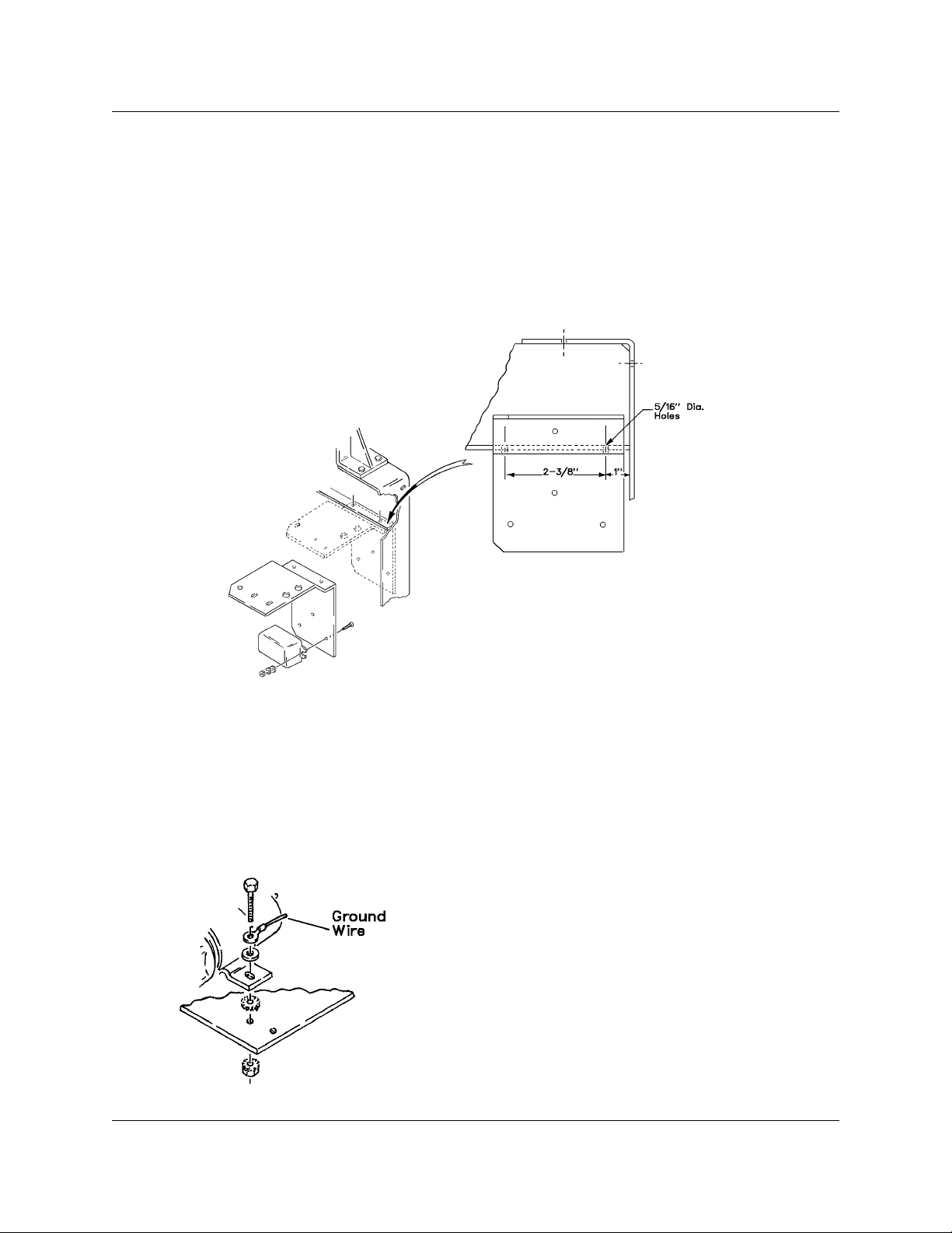
18. Using the supplied bracket as a template, drill two 5/16" diameter holes in the lifting yoke located as
shown in Figure 4. Mount the relay to the inside of this bracket using two #6 screws, flat and lockwashers,
and nuts supplied.
Figure 4
19. Attach bracket to underside of lifting yoke with 1/4-20 bolts, toothed washer, and nuts supplied. Place
toothed lockwasher under one bolt head to assure good electrical grounding.
20. Install solenoid on top side of bracket. Adjust position so that solenoid is pointing towards fuel shutoff
pulley. Secure with 1/4-20 screws, toothed washer and nuts supplied. Place one toothed washer between
bracket and solenoid base to assure good electrical grounding. (Refer to Figure 5).
21. Attach tension spring supplied in kit to solenoid plunger
using two 1/4-28 nuts supplied. Center spring on screw.
22. Making sure cable lays in groove of pulley, connect cable
from shutoff pulley to tension spring, slipping loop over hook of
spring. Linkage length adjustment may be required. Small adjustment for fine tuning can be accomplished by adjusting the
nuts on the solenoid plunger.
Larger length adjustments will be required on the MA-4030D
and MA-4535D, and can be made by adjusting the cable length
prior to installing. Loosen the nuts on the clamp holdingthe loop
in the cable and pull more cable through — approximate length
Figure 5
from flat pulley face to end of cable loop is 6 inches.
March 13, 2000 Revised Page 3

430429-080
Figure 6
23. Adjust so that cable is tight without flexingthe tension spring when solenoid plunger isextended. When
properly adjusted, the tension spring should flex approximately 1/8 inch when plunger is fully compressed.
Cut off excess cable length.
24. Remove throttle cable from old bracket. Retain clamp (11); discard bracket.
25. Place one cable stop (removed earlier) on throttle cable.
26. Thread cable through hole in small pivot on the speed control arm.
27. Place second cable stop (removed earlier) onto cable. Adjust cable stops so the valve can be fully
pushed open and closed. Cut off any excess cable length. (Refer to Figure 7 for proper installation.)
28. Install clamp from throttle cable on bottom side of new bracket in small hole in front (beside solenoid
mounting holes) using #10 screw and nut (supplied) and secure throttle cable in place.
29. Drain approximately 4 to 6 quarts of coolant
from radiator. This may be done from the drain
cock on the engine block on the right-hand side
while facing thecontrol panel. Funnelcoolant into
a container and save for reuse.
NOTE: The kit is supplied with two temperature switches. The finer thread one
(3/8) is for the 3-cylinder engine. The
coarser thread one (1/2) is for the 4-cylinder engine.
30. On the 3-152 engine (Model MA-4030D or
MA-4535D), remove the 3/8 pipe plug located on
the left side of the water pump (when facing front
of engine) and install the water temperature
switch. Connect per connection diagram. Use the
#209 wire with two ring tongue terminals. Discard
the other.
31. On the 4-236 engine (Model MA-5040D),
remove the 1/2 pipe plug located on the top right
of the water pump (when facing front of engine)
and install the watertemperature switch. Connect
Figure 7
Page 4 March 13, 2000 Revised
per connection diagram. Use the #209 wire with
one quick connect terminal. Discard the other.

430429-080
32. Refill radiator with coolant drained in Step 29.
33. Remove the 1/4- and 3/8-inch hole plugs located in the lower right-hand corner of the control panel.
Mount the “Murphy” magnetic switch to the control panel using the nut supplied with the switch.
34. Attach fuseholder to bracket (hole closest to lifting yoke).
35. Install new “Operation and Maintenance” label over existing label located on inside surface of left-hand
door. Wire the engine protection shutdown system per Connection Diagram, using the wires and wire ties
supplied in kit.
36. Referring to the Owner’s Manual connection diagram, disconnect #25 black wire from the alternator
light and connect the proper end of diode assembly 490597-2 (the one with quick-connect receptacles on
each end) to the light and the other end to #25 black wire, using the terminal coupler supplied. Be sure that
you do
the right direction as indicated by the Connection Diagram.
hose to fuel lines with wire tie if necessary.
not disconnect the resistor on the alternator light (if so equipped) and that the diode is connected in
37. Attach diode assembly (with ring terminals) to the solenoid.See Connection Diagram for orientation.
38. Ground wire attaches to solenoid mounting screw as shown in Figure 5.
39. Assure that PCV hose is clear from cable linkage during operation (4-cylinder engine). Tie down PCV
March 13, 2000 Revised Page 5

430429-080
Figure 8 Engine Protection Shutdown Device Kit
494170-1 (Properly Installed)
Page 6 March 13, 2000 Revised

430429-080
Parts List for Figure 9
Quantity
Item Part per Application
No. No. Description Assembly Code
494170-1 . Kit - Engine Protection 1 A
494170-3 . Kit - Engine Protection 1 B
1 493799 . Solenoid - 20 Lb. Pull 1 All
2 493804 . Bracket - Mounting 1 A
493804-1 . Bracket - Mounting 1 B
3 402658 . Fuseholder 1 All
4 16DA-4252-6 . Fuse - 8 Amp, MDL, Slow Blow 4 All
5 400562-46 . Spring - Torsion 1 All
6 493814 . Linkage - Fuel Shutoff 1 All
7 400562-45 . Spring - Tension 1 All
8 W-11280-3 . Nut - 1/4-28, Hex, ST. (For Sol. Plunger) 2 All
9 402119-6 . Screw - 1/4-20 x 1, HHCS, ST. 4 All
10 50MS-732-0 . Nut - 1/4-20, Hex, Keps, ST. 4 All
11 403091-2 . Plug - Hole, Plastic (Optional Use) 1 All
12 W-11112-1 . Screw - #10-24 x 1/2, Rd. Hd. ST. 1 All
13 50MS-732-5 . Nut - #10-24, Hex, Keps, ST. 1 All
14 490597-1 . Diode - Assembly 1 All
— 406224 . Switch - Water Temp. (Mts. On 3-Cylinder
Engine) 1 All
— 494169 . Switch - Water Temp. (Mts. On 4-Cylinder
Engine) 1 All
15 404473 . Switch - Magnetic 1 All
— 493825 . Label - Maintenance (Mts. Inside Door) 1 All
16 493816 . Pivot - Throttle 1 All
17 490597-2 . Diode - Assembly 1 All
18 400778 . Terminal - Coupler, Ins. 1 All
19 W-11242-5 . Washer - 1/4, FL, ST. 2 All
20 W-11263-4 . Washer - LK, IET, 1/4 2 All
21 W-11110-1 . Screw - #6-32 x 1/4, Rd. Hd. ST. 1 All
22 403056-8 . Relay - 12 V DC 1 All
23 W-11110-4 . Screw - #6-32 x 1/2 Rd. Hd. ST. 2 All
24 W-11254-1 . Washer - #6, LK, ST. 2 All
25 W-11245-2 . Washer - #6, FL, Brs. 2 All
26 W-11287-2 . Nut - #6-32, Hex, SCR, ST. 2 All
— W-11287-9 . Nut - #8-36, UNF 1 All
— Not Illustrated
March 13, 2000 Revised Page 7

430429-080
INSTALLATION OF THE ENGINE PROTECTION SHUTDOWN KIT WHEN
THE IDLE DEVICE KIT (493820) IS ALREADY INSTALLED
These instructions are for the installation of a engine protection shutdown kit (494170-1) on either a 3- or
4-cylinder Perkins diesel engine when an automatic idle kit (493820) is already installed.
Figure 9 Engine Protection Shutdown
and Idle Device Kit (Properly Installed)
1. Remove cable support bracket and throttle cable from injection pump and fuel shutoff arm.
2.Remove throttle cable and “FuelShutoff”label from control panel. Discard thethrottlecable and the cable
support bracket. Install plastic hole plug supplied in hole in control panel.
3. Refer to ENGINE PROTECTION SHUTDOWN KIT, Steps 4 through 13. Install relays “back to back” on
bracket.
4. Install solenoidon top side of bracket. Adjust the position so that the solenoid is pointing towards the fuel
shutoff pulley. Attach using the hardware holding the speed control solenoid in place. Ground leads and
hardware to be attached per Figure 9, View A.
5. Refer to ENGINE PROTECTION SHUTDOWN KIT, Steps 21 through 23.
6. Refer to ENGINE PROTECTION SHUTDOWN KIT, Steps 29 through 39. (Additional fuseholder mounts
in available hole next to speed control solenoid fuseholder.)
Page 8 March 13, 2000 Revised

430429-080
OPTIONAL ENGINE PROTECTION LINKAGE FOR 3.152 PERKINS ENGINES
These instructions need to be followed when installing the optional rigid linkage specifically designed for
the Perkins 3.152 powered units only (Mega-Arc 4030D or the Mega-Arc 4535D). This linkageis optional for
use,and may provide an easierinstallationthanthe standard flexible linkage also includedwiththis kit. Either
linkage will give adequate service and the choiceof which to use is up to theinstaller. In either case, the rigid
linkage assembly will work only with the 3.152 engines and if installing a kit on a 4.236 engine (Mega-Arc
5040D) you must use the flexible cable linkage.
Follow the directions in the original instruction sheet, Steps 1 through 4, disregard Steps 5 through 13,
perform Steps 14 through 21, then use the following addendum instructions and photo to properly install the
rigid linkage parts.
1/4 HEX SCREW
FLAT WASHER
KEPS LOCK NUT
LOWER
LINKAGE
COTTER PIN
#8 HEX SCREW
LOCK WASHER
BRASS FLAT WASHER
UPPER
LINKAGE
Remount fuel shutoff arm removed in Step4 (from original instructions), using nut and lockwasher . Assure
the slot of the arm is aligned with the shoulder of the shaft. Attach upper linkage (with formed offset) from
this kit to the free end of the tension spring on solenoid. Spring should lie on top of the linkage and a flat
washer should beplaced against theloop end of spring.Assemble with 1/4-20x 1/2 screw and with the Keps
lock nut against flat washer.
Place lower linkage pivot pin into hole on the speed control arm. Assemble two halves of linkage using hex
head #8 screws, lockwashers, and brass flat washers. Lower linkage should be below the upper linkage.
Screwsshouldpositionapproximatelyhalfwayinthelengthofslotforinitialsetting. Secure pivot pintocontrol
arm placing 3/64-diameter cotter pin into hole in pivot. Bend cotter pin around pivot to assure clearance of
other components.
To fine tune linkage length, fully compress solenoid plunger, making sure the plunger is bottomed in the
solenoid. Adjust linkage lengthusing the #8 hexscrews or the 1/4nuts on the solenoidplunger shaft, or both.
Length is correct when the fuel shutdown arm is against the stop closest to the solenoid and the tension
spring is stretched 1/16 to 1/8 inch with the solenoidplunger bottomed out. Tighten fully the #8 hex screw to
assure linkage length won’t change as solenoid cycles.
Disregard Steps 22 and 23, and then continue with Step 24 through the end to finish installation
March 13, 2000 Revised Page 9

430429-080
PARTS LIST FOR OPTIONAL ENGINE PROTECTION LINKAGE KIT
Item Part Description Qty Application
No Number per Code
Assy
1 50MS-732-1 NUT, 1/4 -20, HEX, KEPS 1 All
2 W-11242-5 WASHER, 1/4, FLAT, STEEL 1 All
3 W-11254-2 WASHER, #8, LOCK, STD 2 All
4 W-11245-15 WASHER, #8, FLAT, BRASS 2 All
5 402812-2 SCREW, #8-32 X 3/8, HEX, STEEL 2 All
6 402119-2 SCREW, 1/4-20 X 1/2, HEX, STEEL 1 All
7 800081-1 PIN, COTTER, 3/64 1 All
8 800079 LINKAGE, UPPER 1 All
9 800080 LINKAGE, LOWER 1 All
Page 10 March 13, 2000 Revised

DIAGRAMS
430429-080
INSTRUCTION
SHEET
494170-1
494170-3
UNIT
SPEC MODEL
S-6298C MA-4030D 494148
S-6495A MA-4535D
S-6429B MA-5040D 494147
S-6298D MA-4030D 494148
S-6495A MA-4535D
S-6429C MA-5040D 494147
S-6298E MA-4030D 800045
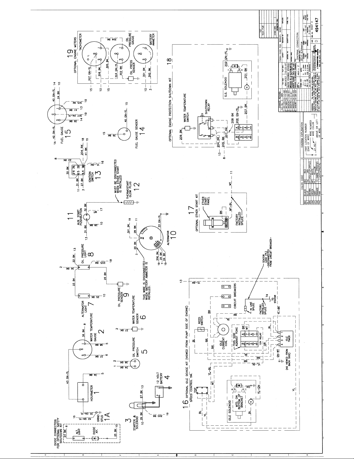
CONNECTION
DIAGRAM
Sheet 3
494148A
Sheet 3
Sheet 3
Sheet 3
494148A
Sheet 3
Sheet 3
Sheet 3
March 13, 2000 Revised
S-6429D MA-5040D 800044Sheet 3


STATEMENT OF WARRANTY
LIMITED WARRANTY:ThermalArc®, Inc., AThermadyneCompany,warrantsthat its products will be free ofdefectsinworkmanship
ormaterial.Should any failuretoconform to this warrantyappear within the timeperiodapplicable to theThermalArcproducts as stated
below, Thermal Arc shall, upon notification thereof and substantiation that the product has been stored, installed, operated, and
maintained in accordancewithThermal Arc’s specifications,instructions,recommendations and recognized standard industry practice,
and not subject to misuse, repair, neglect, alteration, or accident, correct such defects by suitable repair or replacement, at Thermal
Arc’s sole option, of any components or parts of the product determined by Thermal Arc to be defective.
THERMAL ARC MAKES NO OTHER WARRANTY, EXPRESS OR IMPLIED. THIS WARRANTY IS EXCLUSIVE AND IN LIEU OF
ALL OTHERS, INCLUDING, BUT NOT LIMITED TO ANY WARRANTY OF MERCHANTABILITY OR FITNESS FOR ANY
PARTICULAR PURPOSE.
LIMITATION OF LIABILITY: Thermal Arc shall not under any circumstancesbe liable for special or consequential damages, such as,
but not limited to, damage or loss of purchased or replacement goods, or claims of customers of distributor (hereinafter “Purchaser”)
for service interruption.TheremediesofthePurchaserset forth herein are exclusive and the liability of Thermal Arc with respect to any
contract, or anything done in connection therewith such as the performance or breach thereof, or from the manufacture, sale, delivery,
resale, or use of any goods covered by or furnished by Thermal Arc whether arising out of contract, negligence, strike tort, or under
any warranty, or otherwise, shall not, except as expressly provided herein, exceed the price of the goods upon which such liability is
based. No employee, agent, or representative of Thermal Arc is authorized to change this warranty in any way or grant any other
warranty.
PURCHASER’SRIGHTS UNDERTHISWARRANTYAREVOID IFREPLACEMENT PARTSOR ACCESSORIESARE USEDWHICH
IN THERMAL ARC’S SOLE JUDGMENT MAY IMPAIR THE SAFETY OR PERFORMANCE OF ANY THERMAL ARC PRODUCT.
PURCHASER’S RIGHTS UNDER THIS WARRANTY ARE VOID IF THE PRODUCT IS SOLD TO PURCHASER BY
NON-AUTHORIZED PERSONS.
Except with regards to the products listed below, this warranty shall remain effective three (3) years from the date Thermal Arc’s
authorized distributor delivers the product to Purchaser, but in no event more than (4) years from the date Thermal Arc delivers the
product to the authorized distributor.
Shorter warranty periods apply to the products listed below. On these products, the warranty is effective for the time stated below
beginning on the date that the authorized distributor delivers the products to the Purchaser. Notwithstanding the foregoing, in no event
shall the warranty period extend more than the time stated plus one year from the date Thermal Arc delivered the product to the
authorized distributor.
ALL OTHER P-WEE, PRO-LITE
POWER SUPPLIES POWER SUPPLIES PRO-PLUS, PRO-WAVE LABOR
MAIN POWER MAGNETICS (STATIC & ROTATING) 3 YEARS 2 YEARS 1 YEAR
ORIGINAL MAIN POWER RECTIFIER 3 YEARS 2 YEARS 1 YEAR
CONTROL PC BOARD 3 YEARS 2 YEARS 1 YEAR
ALLOTHERCIRCUITSANDCOMPONENTSINCLUDING 1 YEAR 1 YEAR 1 YEAR
BUT NOT LIMITED TO, CONTACTORS, RELAYS,
SOLENOID, PUMPS, POWER SWITCHING SEMI-CONDUCTORS
ENGINES: ENGINES ARE NOT WARRANTED BY THERMAL ARC, ALTHOUGH MOST ARE WARRANTED BY THE ENGINE
MANUFACTURER. SEE THE ENGINE MANUFACTURES WARRANTY FOR DETAILS
CONSOLES, CONTROL EQUIPMENT, HEAT 1 YEAR 1 YEAR 1 YEAR
EXCHANGES, AND ACCESSORY EQUIPMENT
TORCH AND LEADS 180 DAYS 180 DAYS 180 DAYS
REPAIR/REPLACEMENT PARTS 90 DAYS 90 DAYS 90 DAYS
Warranty repairsorreplacementclaimsunder this limited warranty mustbesubmittedto Thermal Arc by anauthorizedThermalArc®repair
facility within thirty (30) days of the repair. No transportation costs of any kind will be paid under this warranty. Transportation charges to
sendproductsto anauthorizedwarranty repairfacility shallbe the responsibilityof thecustomer.All returnedgoodsshall beatthe customer’s
risk and expense. This warranty supersedes all previous Thermal Arc warranties.
.
Thermal Arc®is a Registered Trademark of Thermadyne Industries Inc.
Thermal Arc Inc. Effective January 4, 1999
Troy, Ohio 45373 830538
 Loading...