


50
60
Hz
Art # A-10934
211i
Operating Manual
Revision: AB Issue Date: February 29, 2012 Manual No.: 0-5225
Operating Features:
FABRICATOR
®
MULTI PROCESS WELDING
INVERTER

WE APPRECIATE YOUR BUSINESS!
Congratulations on your new Thermal Arc product. We are proud
to have you as our customer and will strive to provide you with
the best service and reliability in the industry. This product
is backed by our extensive warranty and world-wide service
network. To locate your nearest distributor or service agency call
+44 (0) 1257 261 755, or visit us on the web at www.Thermalarc.com.
This Operating Manual has been designed to instruct you on the correct
use and operation of your Thermal Arc product. Your satisfaction with
this product and its safe operation is our ultimate concern. Therefore
please take the time to read the entire manual, especially the Safety
Precautions. They will help you to avoid potential hazards that may
exist when working with this product.
We have made every effort to provide you with accurate instructions,
drawings, and photographs of the product(s) while writing this manual.
However errors do occur and we apologize if there are any contained
in this manual.
Due to our constant effort to bring you the best products, we may
make an improvement that does not get reflected in the manual. If you
are ever in doubt about what you see or read in this manual with the
product you received, then check for a newer version of the manual on
our website or contact our customer support for assistance.
YOU ARE IN GOOD COMPANY!
The Brand of Choice for Contractors and Fabricators Worldwide.
Thermal Arc is a Global Brand of Arc Welding Products for Thermadyne
Industries Inc. We manufacture and supply to major welding industry
sectors worldwide including; Manufacturing, Construction, Mining,
Automotive, Aerospace, Engineering, Rural and DIY/Hobbyist.
We distinguish ourselves from our competition through market-leading,
dependable products that have stood the test of time. We pride ourselves
on technical innovation, competitive prices, excellent delivery, superior
customer service and technical support, together with excellence in
sales and marketing expertise.
Above all, we are committed to develop technologically advanced
products to achieve a safer working environment within the welding
industry.

!
WARNINGS
Read and understand this entire Manual and your employer’s safety practices before installing,
operating, or servicing the equipment.
While the information contained in this Manual represents the Manufacturer’s best judgment,
the Manufacturer assumes no liability for its use.
Operating Manual Number 0-5225 for:
Thermal Arc Fabricator 211i Inverter Power Supply Part Number W1004206
Thermal Arc Fabricator 211i Inverter System Part Number W1004207
Published by:
Thermadyne Europe
Europa Building
Chorley Industrial Park
Chorley, Lancaster,
England, PR6 7BX
www.thermalarc.com
Copyright 2011 by
Thermadyne Industries, Inc.
All rights reserved.
Reproduction of this work, in whole or in part, without written permission of the
publisher is prohibited.
The publisher does not assume and hereby disclaims any liability to any party for any
loss or damage caused by any error or omission in this Manual, whether such error
results from negligence, accident, or any other cause.
Publication Date: December 23, 2011
Revision AB Date: February 29, 2012
Record the following information for Warranty purposes:
Where Purchased: ____________________________________
Purchase Date: ____________________________________
Equipment Serial #: ____________________________________

TABLE OF CONTENTS
SECTION 1:
SAFETY INSTRUCTIONS AND WARNINGS ....................................................... 1-1
1.01 Arc Welding Hazards ....................................................................................... 1-1
1.02 Principal Safety Standards .............................................................................. 1-5
1.03 Symbol Chart .................................................................................................. 1-6
1.04 Declaration Of Conformity .............................................................................. 1-7
SECTION 2: INTRODUCTION ............................................................................. 2-1
2.01 How To Use This Manual ................................................................................ 2-1
2.02 Equipment Identification ................................................................................. 2-1
2.03 Receipt Of Equipment ..................................................................................... 2-1
2.04 Description ..................................................................................................... 2-1
2.05 User Responsibility ......................................................................................... 2-2
2.06 Transportation Methods .................................................................................. 2-2
2.07 Packaged Items .............................................................................................. 2-2
2.08 Duty Cycle ....................................................................................................... 2-3
2.09 Specifications ................................................................................................. 2-4
2.10 Optional Accessories ...................................................................................... 2-5
SECTION 3: INSTALLATION OPERATION AND SETUP ................................................. 3-1
3.01 Environment ................................................................................................... 3-1
3.02 Location .......................................................................................................... 3-1
3.03 Ventilation ....................................................................................................... 3-1
3.04 Mains Supply Voltage Requirements .............................................................. 3-1
3.05 Electromagnetic Compatibility ........................................................................ 3-2
3.06 Power Source Controls, Indicators and Features ............................................ 3-4
SECTION 4:
BASIC WELDING GUIDE ............................................................................ 4-1
4.01 MIG (GMAW/FCAW) Basic Welding Technique ............................................... 4-1
4.02 MIG (GMAW/FCAW) Welding Troubleshooting ............................................... 4-7
4.03 STICK (MMA) Basic Welding Technique ....................................................... 4-10
4.04 STICK (MMA) Welding Troubleshooting ....................................................... 4-20
4.05 TIG (GTAW) Basic Welding Technique .......................................................... 4-22
4.06 TIG (GTAW) Welding Problems ..................................................................... 4-24
SECTION 5: POWER SOURCE PROBLEMS AND ROUTINE SERVICE REQUIREMENTS ............ 5-1
5.01 Power Source Problems ................................................................................. 5-1
5.02 Routine Service and Calibration Requirements ............................................... 5-2
5.03 Cleaning the Welding Power Source ............................................................... 5-4
5.04 Cleaning the Feed Rolls ................................................................................... 5-5

TABLE OF CONTENTS
SECTION 6:
KEY SPARE PARTS ................................................................................... 6-1
6.01 Power Source Spare Parts .............................................................................. 6-1
APPENDIX: FABRICATOR 211i CIRCUIT DIAGRAM .................................................... A-1
THERMAL ARC - LIMITED WARRANTY TERMS
TERMS OF WARRANTY – JANUARY 2011


SAFETY INSTRUCTIONS FABRICATOR 211i
Manual 0-5225 1-1 SAFETY INSTRUCTIONS AND WARNINGS
1.01 Arc Welding Hazards
WARNING
ELECTRIC SHOCK can kill.
Touching live electrical parts can cause
fatal shocks or severe burns. The electrode
and work circuit is electrically live whenever the output is on. The input power circuit and machine internal circuits are also
live when power is on. In semi-automatic
or automatic wire welding, the wire, wire
reel, drive roll housing, and all metal parts
touching the welding wire are electrically
live. Incorrectly installed or improperly
grounded equipment is a hazard.
1. Do not touch live electrical parts.
2. Wear dry, hole-free insulating gloves and body
protection.
3. Insulate yourself from work and ground using dry
insulating mats or covers.
4. Disconnect input power or stop engine before
installing or servicing this equipment. Lock input
power disconnect switch open, or remove line
fuses so power cannot be turned on accidentally.
5. Properly install and ground this equipment
according to its Owner’s Manual and national,
state, and local codes.
6. Turn OFF all equipment when not in use.
Disconnect power to equipment if it will be left
unattended or out of service.
7. Use fully insulated electrode holders. Never dip
holder in water to cool it or lay it down on the
ground or the work surface. Do not touch holders
connected to two welding machines at the same
time or touch other people with the holder or
electrode.
8. Do not use worn, damaged, undersized, or poorly
spliced cables.
9. Do not wrap cables around your body.
10. Ground the workpiece to a good electrical (earth)
ground.
11. Do not touch electrode while in contact with the
work (ground) circuit.
12. Use only well-maintained equipment. Repair or
replace damaged parts at once.
13. In confined spaces or damp locations, do not use
a welder with AC output unless it is equipped with
a voltage reducer. Use equipment with DC output.
14. Wear a safety harness to prevent falling if working
above floor level.
15. Keep all panels and covers securely in place.
SECTION 1:
SAFETY INSTRUCTIONS AND WARNINGS
!
WARNING
PROTECT YOURSELF AND OTHERS FROM POSSIBLE SERIOUS INJURY OR DEATH. KEEP CHILDREN
AWAY. PACEMAKER WEARERS KEEP AWAY UNTIL CONSULTING YOUR DOCTOR. DO NOT LOSE THESE
INSTRUCTIONS. READ OPERATING/INSTRUCTION MANUAL BEFORE INSTALLING, OPERATING OR
SERVICING THIS EQUIPMENT.
Welding products and welding processes can cause serious injury or death, or damage to other equipment or
property, if the operator does not strictly observe all safety rules and take precautionary actions.
Safe practices have developed from past experience in the use of welding and cutting. These practices must be
learned through study and training before using this equipment. Some of these practices apply to equipment
connected to power lines; other practices apply to engine driven equipment. Anyone not having extensive
training in welding and cutting practices should not attempt to weld.
Safe practices are outlined in the European Standard EN60974-1 entitled: Safety in welding and allied processes
Part 2: Electrical. This publication and other guides to what you should learn before operating this equipment
are listed at the end of these safety precautions. HAVE ALL INSTALLATION, OPERATION, MAINTENANCE,
AND REPAIR WORK PERFORMED ONLY BY QUALIFIED PEOPLE.

FABRICATOR 211i SAFETY INSTRUCTIONS
SAFETY INSTRUCTIONS AND WARNINGS 1-2 Manual 0-5225
WARNING
ARC RAYS can burn eyes and skin; NOISE
can damage hearing. Arc rays from the
welding process produce intense heat and
strong ultraviolet rays that can burn eyes
and skin. Noise from some processes can
damage hearing.
1. Wear a welding helmet fitted with a proper shade
of filter (see ANSI Z49.1 listed in Safety Standards)
to protect your face and eyes when welding or
watching.
2. Wear approved safety glasses. Side shields
recommended.
3. Use protective screens or barriers to protect others
from flash and glare; warn others not to watch the
arc.
4. Wear protective clothing made from durable,
flame-resistant material (wool and leather) and
foot protection.
5. Use approved ear plugs or ear muffs if noise level
is high.
6. Never wear contact lenses while welding.
AWS F2.2:2001 (R2010), Adapted with permission of the American Welding Society (AWS), Miami, Florida
Guide for Shade Numbers
Process
Electrode Size in.
(mm)
Arc Current
(Amperes)
Minimum
Protective
Shade
Suggested*
Shade No.
(Comfort)
Shielded Metal Arc Welding
(SMAW)
Less than 3/32 (2.4)
3/32-5/32 (2.4-4.0)
5/32-1/4 (4.0-6.4)
More than 1/4 (6.4)
Less than 60
60-160
160-250
250-550
7
8
10
11
10
12
14
Gas Metal Arc Welding (GMAW)
and Flux Cored Arc Welding
(FCAW)
Less than 60
60-160
160-250
250-550
7
10
10
10
11
12
14
Gas Tungsten arc Welding
(GTAW)
Less than 50
50-150
150-500
8
8
10
10
12
14
Air Carbon Arc Cutting (CAC-A)
(Light)
(Heavy)
Less than
500
500-1000
10
11
12
14
Plasma Arc Welding (PAW)
Less than 20
20-100
100-400
400-800
6
8
10
11
6 to 8
10
12
14
Plasma Arc Cutting (PAC)
Less than 20
20-40
40-60
60-80
80-300
300-400
400-800
4
5
6
8
8
9
10
4
5
6
8
9
12
14
* As a rule of thumb, start with a shade that is too dark to see the weld zone. Then go to a lighter
shade which gives sufficient view of the weld zone without going below the minimum. In oxyfuel gas
welding, cutting, or brazing where the torch and/or the flux produces a high yellow light, it is desirable
to use a filter lens that absorbs the yellow or sodium line of the visible light spectrum.

SAFETY INSTRUCTIONS FABRICATOR 211i
Manual 0-5225 1-3 SAFETY INSTRUCTIONS AND WARNINGS
WARNING
FUMES AND GASES can be hazardous to
your health.
Welding produces fumes and gases.
Breathing these fumes and gases can be
hazardous to your health.
1. Keep your head out of the fumes. Do not breathe
the fumes.
2. If inside, ventilate the area and/or use exhaust at
the arc to remove welding fumes and gases.
3. If ventilation is poor, use an approved air-supplied
respirator.
4. Read the Material Safety Data Sheets (MSDSs)
and the manufacturer’s instruction for metals,
consumables, coatings, and cleaners.
5. Work in a confined space only if it is well ventilated,
or while wearing an air-supplied respirator.
Shielding gases used for welding can displace air
causing injury or death. Be sure the breathing air
is safe.
6. Do not weld in locations near degreasing, cleaning,
or spraying operations. The heat and rays of the
arc can react with vapours to form highly toxic
and irritating gases.
7. Do not weld on coated metals, such as galvanized,
lead, or cadmium plated steel, unless the coating
is removed from the weld area, the area is well
ventilated, and if necessary, while wearing an airsupplied respirator. The coatings and any metals
containing these elements can give off toxic fumes
if welded.
WARNING
WELDING can cause fire or explosion.
Sparks and spatter fly off from the
welding arc. The flying sparks and hot
metal, weld spatter, hot workpiece, and
hot equipment can cause fires and burns.
Accidental contact of electrode or welding
wire to metal objects can cause sparks,
overheating, or fire.
1. Protect yourself and others from flying sparks and
hot metal.
2. Do not weld where flying sparks can strike
flammable material.
3. Remove all flammables within 35 ft (10.7 m) of the
welding arc. If this is not possible, tightly cover
them with approved covers.
4. Be alert that welding sparks and hot materials from
welding can easily go through small cracks and
openings to adjacent areas.
5. Watch for fire, and keep a fire extinguisher nearby.
6. Be aware that welding on a ceiling, floor, bulkhead,
or partition can cause fire on the hidden side.
7. Do not weld on closed containers such as tanks
or drums.
8. Connect work cable to the work as close to the
welding area as practical to prevent welding
current from travelling long, possibly unknown
paths and causing electric shock and fire hazards.
9. Do not use welder to thaw frozen pipes.
10. Remove stick electrode from holder or cut off
welding wire at contact tip when not in use.
WARNING
FLYING SPARKS AND HOT METAL can
cause injury.
Chipping and grinding cause flying metal.
As welds cool, they can throw off slag.
1. Wear approved face shield or safety goggles. Side
shields recommended.
2. Wear proper body protection to protect skin.
WARNING
CYLINDERS can explode if damaged.
Shielding gas cylinders contain gas under
high pressure. If damaged, a cylinder can
explode. Since gas cylinders are normally
part of the welding process, be sure to
treat them carefully.
1. Protect compressed gas cylinders from excessive
heat, mechanical shocks, and arcs.
2. Install and secure cylinders in an upright position
by chaining them to a stationary support or
equipment cylinder rack to prevent falling or
tipping.
3. Keep cylinders away from any welding or other
electrical circuits.
4. Never allow a welding electrode to touch any
cylinder.
FABRICATOR 211i SAFETY INSTRUCTIONS
SAFETY INSTRUCTIONS AND WARNINGS 1-4 Manual 0-5225
5. Use only correct shielding gas cylinders,
regulators, hoses, and fittings designed for the
specific application; maintain them and associated
parts in good condition.
6. Turn face away from valve outlet when opening
cylinder valve.
7. Keep protective cap in place over valve except
when cylinder is in use or connected for use.
8. Read and follow instructions on compressed
gas cylinders, associated equipment, and CGA
publication P-1 listed in Safety Standards.
!
WARNING
Engines can be dangerous.
WARNING
ENGINE EXHAUST GASES can kill.
Engines produce harmful exhaust gases.
1. Use equipment outside in open, well-ventilated
areas.
2. If used in a closed area, vent engine exhaust
outside and away from any building air intakes.
WARNING
ENGINE FUEL can cause fire or explosion.
Engine fuel is highly flammable.
1. Stop engine before checking or adding fuel.
2. Do not add fuel while smoking or if unit is near
any sparks or open flames.
3. Allow engine to cool before fuelling. If possible,
check and add fuel to cold engine before beginning
job.
4. Do not overfill tank — allow room for fuel to
expand.
5. Do not spill fuel. If fuelling is spilled, clean up
before starting engine.
WARNING
MOVING PARTS can cause injury.
Moving parts, such as fans, rotors, and belts can cut
fingers and hands and catch loose clothing.
1. Keep all doors, panels, covers, and guards
closed and securely in place.
2. Stop engine before installing or connecting
unit.
3. Have only qualified people remove guards or
covers for maintenance and troubleshooting
as necessary.
4. To prevent accidental starting during servicing,
disconnect negative (-) battery cable from
battery.
5. Keep hands, hair, loose clothing, and tools
away from moving parts.
6. Reinstall panels or guards and close doors
when servicing is finished and before starting
engine.
WARNING
SPARKS can cause BATTERY GASES TO
EXPLODE; BATTERY ACID can burn eyes
and skin.
Batteries contain acid and generate explosive gases.
1. Always wear a face shield when working on a
battery.
2. Stop engine before disconnecting or connecting
battery cables.
3. Do not allow tools to cause sparks when working
on a battery.
4. Do not use welder to charge batteries or jump start
vehicles.
5. Observe correct polarity (+ and –) on batteries.
WARNING
STEAM AND PRESSURIZED HOT
COOLANT can burn face, eyes, and skin.
The coolant in the radiator can be very hot
and under pressure.
1. Do not remove radiator cap when engine is hot.
Allow engine to cool.
2. Wear gloves and put a rag over cap area when
removing cap.
3. Allow pressure to escape before completely
removing cap.

SAFETY INSTRUCTIONS FABRICATOR 211i
Manual 0-5225 1-5 SAFETY INSTRUCTIONS AND WARNINGS
NOTE
Considerations About Welding And The
Effects of Low Frequency Electric and
Magnetic Fields
The following is a quotation from the General Conclusions Section of the U.S. Congress, Office of
Technology Assessment, Biological Effects of Power
Frequency Electric & Magnetic Fields - Background
Paper, OTA-BP-E-63 (Washington, DC: U.S. Government Printing Office, May 1989): “...there is now
a very large volume of scientific findings based on
experiments at the cellular level and from studies with
animals and people which clearly establish that low
frequency magnetic fields interact with, and produce
changes in, biological systems. While most of this
work is of very high quality, the results are complex.
Current scientific understanding does not yet allow us
to interpret the evidence in a single coherent framework. Even more frustrating, it does not yet allow
us to draw definite conclusions about questions of
possible risk or to offer clear science-based advice
on strategies to minimize or avoid potential risks.”
To reduce magnetic fields in the workplace, use the
following procedures.
1. Keep cables close together by twisting or
taping them.
2. Arrange cables to one side and away from the
operator.
3. Do not coil or drape cable around the body.
4. Keep welding Power Source and cables as far
away from body as practical.
ABOUT PACEMAKERS:
The above procedures are among
those also normally recommended for
pacemaker wearers. Consult your doctor
for complete information.
1.02 Principal Safety Standards
Safety in Welding and Cutting, ANSI Standard Z49.1,
from American Welding Society, 550 N.W. LeJeune
Rd., Miami, FL 33126.
Safety and Health Standards, OSHA 29 CFR 1910,
from Superintendent of Documents, U.S. Government
Printing Office, Washington, D.C. 20402.
Recommended Safe Practices for the Preparation for
Welding and Cutting of Containers That Have Held
Hazardous Substances, American Welding Society
Standard AWS F4.1, from American Welding Society,
550 N.W. LeJeune Rd., Miami, FL 33126.
National Electrical Code, NFPA Standard 70, from
National Fire Protection Association, Batterymarch
Park, Quincy, MA 02269.
Safe Handling of Compressed Gases in Cylinders, CGA
Pamphlet P-1, from Compressed Gas Association,
1235 Jefferson Davis Highway, Suite 501, Arlington,
VA 22202.
Code for Safety in Welding and Cutting, CSA Standard
W117.2, from Canadian Standards Association,
Standards Sales, 178 Rexdale Boulevard, Rexdale,
Ontario, Canada M9W 1R3.
Safe Practices for Occupation and Educational Eye and
Face Protection, ANSI Standard Z87.1, from American
National Standards Institute, 1430 Broadway, New
York, NY 10018.
Cutting and Welding Processes, NFPA Standard
51B, from National Fire Protection Association,
Batterymarch Park, Quincy, MA 02269.

FABRICATOR 211i SAFETY INSTRUCTIONS
SAFETY INSTRUCTIONS AND WARNINGS 1-6 Manual 0-5225
1.03 Symbol Chart
Note that only some of these symbols will appear on your model.
Gas Tungsten Arc
Welding (GTAW)
Air Carbon Arc
Cutting (CAC-A)
Constant Current
Constant Voltage
Or Constant Potential
High Temperature
Fault Indication
Arc Force
Touch Start (GTAW)
Variable Inductance
Voltage Input
Single Phase
Three Phase
Three Phase Static
Frequency ConverterTransformer-Rectifier
Dangerous Voltage
OFF
ON
Panel/Local
Shielded Metal
Arc Welding (SMAW)
Gas Metal Arc
Welding (GMAW)
Increase/Decrease
Circuit Breaker
AC Auxiliary Power
Remote
Duty Cycle
Percentage
Amperage
Voltage
Hertz (cycles/sec)
Frequency
Negative
Positive
Direct Current (DC)
Protective Earth
(Ground)
Line
Line Connection
Auxiliary Power
Receptacle RatingAuxiliary Power
Art # A-10663
115V 15A
t
t1
t2
%
X
IPM
MPM
t
V
Fuse
Wire Feed Function
Wire Feed T owards
Workpiece With
Output Voltage OFF.
Preflow Time
Postflow Time
Spot Time
Spot Weld Mode
Continuous Weld
Mode
Press to initiate wirefeed and
welding, release to stop.
Purging Of Gas
Inches Per Minute
Meters Per Minute
Welding Gun
Burnback Time
Press and hold for preflow, release
to start arc. Press to stop arc, and
hold for preflow.
4 Step Trigger
Operation
2 Step Trigger
Operation
S
See Note
See Note
SAFETY INSTRUCTIONS FABRICATOR 211i
Manual 0-5225 1-7 SAFETY INSTRUCTIONS AND WARNINGS
1.04 Declaration Of Conformity
Manufacturer: Thermadyne Industries
Address: 82 Benning Street
West Lebanon, New Hampshire 03784
USA
The equipment described in this manual conforms to all applicable aspects and regulations of the ‘Low Voltage
Directive’ (European Council Directive 73/23/EEC as amended by Council Directive 93/68/EEC) and to the
National legislation for the enforcement of this Directive.
The equipment described in this manual conforms to all applicable aspects and regulations of the “EMC
Directive” (European Council Directive 89/336/EEC) and to the National legislation for the enforcement of
this Directive.
Serial numbers are unique with each individual piece of equipment and details description, parts used to
manufacture a unit and date of manufacture.
National Standard and Technical Specifications
The product is designed and manufactured to a number of standards and technical requirements. Among
them are:
• CENELECEN50199EMCProductStandardforArcWeldingEquipment.
• ISO/IEC60974-1(BS638-PT10)(EN60974-1)(EN50192)(EN50078)applicabletoweldingequipment
and associated accessories.
• Forenvironmentswithincreasedhazardofelectricalshock,PowerSuppliesbearingtheSmark
conform to EN50192 when used in conjunction with hand torches with exposed cutting tips, if
equipped with properly installed standoff guides.
• Extensiveproductdesignverificationisconductedatthemanufacturingfacilityaspartoftheroutine
design and manufacturing process. This is to ensure the product is safe, when used according to
instructions in this manual and related industry standards, and performs as specified. Rigorous testing
is incorporated into the manufacturing process to ensure the manufactured product meets or exceeds
all design specifications.
• 2002/95/ECRoHSdirective.
!
WARNING
This equipment does not comply with IEC 61000-3-12. If it is connected to a public low voltage
system, it is the responsibility of the installer or user of the equipment to ensure, by consultation
with the distribution network operator if necessary, that the equipment may be connected.
Thermadyne has been manufacturing products for more than 30 years, and will continue to achieve
excellence in our area of manufacture.
Manufacturers responsible representative:
Steve Ward
Operations Director
Thermadyne Europe
Europa Building
Chorley N Industrial Park
Chorley, Lancashire,
England PR6 7BX

FABRICATOR 211i SAFETY INSTRUCTIONS
SAFETY INSTRUCTIONS AND WARNINGS 1-8 Manual 0-5225
This Page Intentionally Blank
INTRODUCTION FABRICATOR 211i
Manual 0-5225 2-1 INTRODUCTION
SECTION 2: INTRODUCTION
2.03 Receipt Of Equipment
When you receive the equipment, check it against the
invoice to make sure it is complete and inspect the
equipment for possible damage due to shipping. If there
is any damage, notify the carrier immediately to file a
claim. Furnish complete information concerning damage
claims or shipping errors to the location in your area
listed in the inside back cover of this manual.
Include all equipment identification numbers as described above along with a full description of the parts
in error.
Move the equipment to the installation site before
un-crating the unit. Use care to avoid damaging the
equipment when using bars, hammers, etc., to un-crate
the unit.
2.04 Description
The Thermal Arc Fabricator 211i is a self contained
single phase multi process welding inverter that is capable of performing MIG (GMAW/FCAW), STICK (MMA)
and LIFT TIG (GTAW) welding processes. The unit is
equipped with an integrated wire feed unit, digital voltage and amperage meters, and a host of other features
in order to fully satisfy the broad operating needs of
the modern welding professional. The unit is also fully
compliant to Standard EN 60974.1.
The Thermal Arc Fabricator 211i provides excellent
welding performance across a broad range of applications when used with the correct welding consumables
and procedures. The following instructions detail how
to correctly and safely set up the machine and give
guidelines on gaining the best efficiency and quality
from the Power Source. Please read these instructions
thoroughly before using the unit.
2.01 How To Use This Manual
To ensure safe operation, read the entire manual, including the chapter on safety instructions and warnings.
Throughout this manual, the words WARNING,
CAUTION, and NOTE may appear. Pay particular attention to the information provided under these headings.
These special annotations are easily recognized as
follows:
!
WARNING
A WARNING gives information regarding
possible personal injury.
CAUTION
A CAUTION refers to possible equipment
damage.
NOTE
A NOTE offers helpful information concern
-
ing certain operating procedures.
You will also notice icons from the safety section appearing throughout the manual. These are to advise
you of specific types of hazards or cautions related to
the portion of information that follows. Some may have
multiple hazards that apply and would look something
like this:
2.02 Equipment Identification
The unit’s identification number (specification or part
number), model, and serial number usually appear on
a nameplate attached to the control panel. In some
cases, the nameplate may be attached to the rear panel.
Equipment which does not have a control panel such
as gun and cable assemblies is identified only by the
specification or part number printed on the shipping
container. Record these numbers on the bottom of page
i for future reference.
FABRICATOR 211i INTRODUCTION
INTRODUCTION 2-2 Manual 0-5225
2.05 User Responsibility
This equipment will perform as per the information contained herein when installed, operated, maintained and
repaired in accordance with the instructions provided.
This equipment must be checked periodically. Defective
equipment (including welding leads) should not be used.
Parts that are broken, missing, plainly worn, distorted or
contaminated, should be replaced immediately. Should
such repairs or replacements become necessary, it is
recommended that such repairs be carried out by appropriately qualified persons approved by Thermal Arc.
Advice in this regard can be obtained by contacting an
Accredited Thermal Arc Distributor.
This equipment or any of its parts should not be altered
from standard specification without prior written approval of Thermal Arc. The user of this equipment shall
have the sole responsibility for any malfunction which
results from improper use or unauthorized modification from standard specification, faulty maintenance,
damage or improper repair by anyone other than appropriately qualified persons approved by Thermal Arc.
2.06 Transportation Methods
This unit is equipped with a handle for carrying purposes.
!
WARNING
ELECTRIC SHOCK can kill. DO NOT TOUCH
live electrical parts. Disconnect input power
conductors from de-energized supply line
before moving the welding power source.
!
WARNING
FALLING EQUIPMENT can cause serious
personal injury and equipment damage.
Lift unit with handles built into the top of the front and
rear moulded panels.
Use handcart or similar device of adequate capacity.
If using a fork lift vehicle, place and secure unit on a
proper skid before transporting.
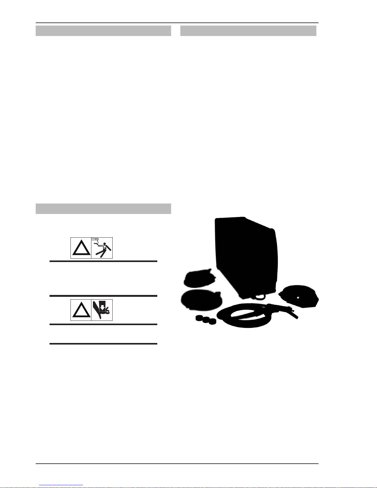
2.07 Packaged Items
Fabricator 211i Power Source (Part No. W1004206)
•Fabricator211iInverterPowerSource
•ShieldingGashoseassembly
•OperatingManual
Fabricator 211i System Part No. (W1004207)
•Fabricator211iInverterPowerSource
•Feedrolls0.6/0.8mm"V"groove(tted),
0.9/1.2mm"V"groove,
1.0/1.2mm"U"groove,
0.8/0.9mm"V"knurled,
•MIGgun3mlong
•ElectrodeHolderwith4mlead
•WorkClampwith4mlead
•ShieldingGashoseassembly
•OperatingManual
Figure 2-1: Fabricator 211i System Packaged W1004207

INTRODUCTION FABRICATOR 211i
Manual 0-5225 2-3 INTRODUCTION
2.08 Duty Cycle
The rated duty cycle of a Welding Power Source, is a statement of the time it may be operated at its rated welding
current output without exceeding the temperature limits of the insulation of the component parts. To explain the
10 minute duty cycle period the following example is used. Suppose a Welding Power Source is designed to operate at a 20% duty cycle, 210 amperes at 24.5 volts. This means that it has been designed and built to provide the
rated amperage (210A) for 2 minutes, i.e. arc welding time, out of every 10 minute period (20% of 10 minutes is
2 minutes). During the other 8 minutes of the 10 minute period the Welding Power Source must idle and allowed
to cool. The thermal cut out will operate if the duty cycle is exceeded.
10 20 30 40 50 60 70 80 90 100 110 120 130 140 150 160 170 180 190 200 210 220
FABRICATOR 211i
Welding Current (AMPS)
SAFE OPERATING REGION
(MIG, TIG & STICK)
0
0
10
20
30
40
60
70
50
80
100
90
Duty Cycle (PERCENTAGE)
MIG
STICK / TIG
Art # A-10935
Figure 2-2: Fabricator 211i Duty Cycle on 230VAC
Welding Current (AMPS)
Duty Cycle (PERCENTAGE)
Art # A-10936
0
10
20
30
40
50
60
70
80
90
100
0102030405060708090100 110 120 130140 150
FABRICATOR 211i
SAFE OPERATING REGION
(MIG, TIG & STICK)
TIG
STICK
MIG
Figure 2-3: Fabricator 211i Duty Cycle on 110VAC

FABRICATOR 211i INTRODUCTION
INTRODUCTION 2-4 Manual 0-5225
2.09 Specifications
Description Fabricator 211i Multi Process Welding Inverter
Power Source Plant Part No. W1004206
Power Source Dimensions H435mm x W266mm x D617mm
Power Source Mass 26kg
Cooling Fan Cooled
Welder Type Multi Process Inverter Power Source
Applicable Standard EN 60974-1
Number of Phases Single Phase
Nominal Supply Voltage 230V±15% 110V±15%
Nominal Supply Frequency 50/60Hz 50/60Hz
Welding Current Range (MIG Mode) 10-210A 10-140A
Wirefeed Speed Range 2.5 - 18 MPM 2.5 - 18 MPM
Effective Input Current (I1eff) 15 Amps 19.6 Amps
Maximum Input Current (I1max) 30 Amps 39 Amps
Single Phase Generator Requirement 7 k VA 4.5 k VA
MIG (GMAW/FCAW) Welding Output, 40ºC, 10
min
210A @ 20%, 24.5V
130A @ 60%, 20.5V
101A @ 100%, 19.1V
140A @ 20%, 21.0V
99A @ 60%, 19.0V
77A @ 100%, 17.9V
STICK (MMA) Welding Output, 40ºC, 10 min. 200A @ 25%, 28.0V
130A @ 60%, 25.2V
101A @ 100%, 24.0V
125A @ 25%, 25.0V
80A @ 60%, 23.2V
60A @ 100%, 22.4V
TIG (GTAW) Welding Output, 40ºC, 10 min. 200A @ 25%, 18.0V
130A @ 60%, 15.2V
101A @ 100%, 14.0V
150A @ 35%, 16.0V
115A @ 60%, 14.6V
90A @ 100%, 13.6V
Open circuit voltage 79V
Protection Class IP23S
Table 2-1: Fabricator 211i Specifications
Note 1: The Effective Input Current should be used for the determination of cable size & supply requirements.
Note 2: Motor start fuses or thermal circuit breakers are recommended for this application. Check local requirements for your situation in this regard.
Note 3: Generator Requirements at the Maximum Output Duty Cycle.
NOTE
Additional safety precautions may be required when using unit in an environment with increased hazard of electric shock . Please refer to relevant local standards for further information prior to using in
such areas.
Due to variations that can occur in manufactured products, claimed per
formance, voltages, ratings, all
capacities, measurements, dimensions and weights quoted are approximate only. Achievable capacities
and ratings in use and operation will depend upon correct installation, use, applications, maintenance
and service.

INTRODUCTION FABRICATOR 211i
Manual 0-5225 2-5 INTRODUCTION
2.10 Optional Accessories
26V TIG Torch (4 m) .............................. Part No. 310.090.001
Tweco TWE2 (3 m) 250A MIG Gun . . .. .. . .. .. .. .. . Part No. 161.550.307
Tweco WeldSkill 220A MIG Gun (3 m) ............ Part No. WS220XE-10-3035
Professional 4 Wheel Cart, Dual Cylinder.......... Part No. W4015002
Professional 4 Wheel Cart, Single Cylinder ......... Part No. W4015001
Cart, Single Cylinder .............................. Part No. W4014700
Roll Cage .......................................... Part No. W4015104
Foot Control ....................................... Part No. 10-4016
Pendant Control .................................. Part No. 10-4014
Tweco WeldSkill Helmet .......................... Part No. WHF41001
Feed Roll 0.6/0.8mm V groove (hard), (fitted) .... Part No. 62020
Feed Roll 0.9/1.2mm V groove (hard) ............. Part No. 62022
Feed Roll 0.8/0.9mm U groove (soft) .............. Part No. 62179
Feed Roll 1.0/1.2mm U groove (soft) .............. Part No. 62024
Feed Roll 0.8/0.9mm V knurled (flux cored) ...... Part No. 62028

FABRICATOR 211i INTRODUCTION
INTRODUCTION 2-6 Manual 0-5225
This Page Intentionally Blank

INSTALLATION/SETUP FABRICATOR 211i
Manual 0-5225 3-1 INSTALLATION/SETUP
3.01 Environment
This unit is designed for use in environments with
increased hazard of electric shock as outlined in EN
60974.1. Additional safety precautions may be required
when using unit in an environment with increased
hazard of electric shock. Please refer to relevant local
standards for further information prior to using in such
areas.
A. Examples of environments with increased hazard of
electric shock are:
1. In locations in which freedom of movement
is restricted, so that the operator is forced to
perform the work in a cramped (kneeling, sitting or lying) position with physical contact with
conductive parts.
2. In locations which are fully or partially limited
by conductive elements, and in which there is
a high risk of unavoidable or accidental contact
by the operator.
3. In wet or damp hot locations where humidity
or perspiration considerably reduces the skin
resistance of the human body and the insulation
properties of accessories.
B. Environments with increased hazard of electric
shock do not include places where electrically conductive parts in the near vicinity of the operator, which can
cause increased hazard, have been insulated.
3.02 Location
Be sure to locate the welder according to the following
guidelines:
A. In areas, free from moisture and dust.
B. Ambient temperature between 0°C (32°F) to 40°C
(104°F).
C. In areas, free from oil, steam and corrosive gases.
D. In areas, not subjected to abnormal vibration or
shock.
E. In areas, not exposed to direct sunlight or rain.
SECTION 3: INSTALLATION OPERATION AND SETUP
F. Place at a distance of 1 foot or more from walls or
similar that could restrict natural air flow for cooling.
G. The enclosure design of this power source meets
the requirements of IP23S as outlined in EN 60529.
H. Precautions must be taken against the power source
toppling over. The power source must be located on
a suitable horizontal surface in the upright position
when in use.
WARNING
This equipment should be electrically connected by a qualified electrician.
3.03 Ventilation
!
WARNING
Since the inhalation of welding fumes can
be harmful, ensure that the welding area is
effectively ventilated.
3.04 Mains Supply Voltage
Requirements
The Mains supply voltage
should be within ± 15% of the rated Mains supply voltage. Too low of a supply voltage may cause poor welding
performance or wirefeeder malfunction. Too high of a
supply voltage will cause components to overheat and
possibly fail.
WARNING
The Fabricator 211i must be electrically
connected by a qualified electrical tradesperson. Damage to the PCA (Power Control
Assembly) could occur if 276 VAC or higher
is applied to the Primary Power Cable

FABRICATOR 211i INSTALLATION/SETUP
INSTALLATION/SETUP 3-2 Manual 0-5225
50/60 Hz
Single Phase
Primary Supply
Lead Size
Minimum
Primary Current
Circuit Size
(Vin/Iin)
Minimum
Plug Size
Current & Duty Cycle
MIG TIG STICK
Yes 2.5mm² 230V/15A 15A 20%@210A 25%@200A 25%@200A
Yes 2.5mm² 110V/32A 20A 20%@140A 35%@150A 25%@125A
Table 3-1: Input Power Source Leads for Fabricator 211i
WARNING
ELECTRIC SHOCK can kill; SIGNIFICANT DC VOLTAGE is present after removal of input power. DO
NOT TOUCH live electrical parts.
SHUT DOWN welding power source, disconnect input power employing lockout/tagging procedures. Lock-out/
tagging procedures consist of padlocking line disconnect switch in open position, removing fuses from fuse box,
or shutting OFF and red-tagging circuit breaker or other disconnecting device.
Electrical Input Requirements
Operate the welding power source from a single-phase 50/60 Hz, AC power source. The Welding Power Source
must be:
•Correctlyinstalled,ifnecessary,byaqualiedelectrician.
•Correctlyearthed(electrically)inaccordancewithlocalregulations.
•Connectedtothecorrectsizepowerpoint,fuseandprimarysupplyleadbasedonTable3-1.
WARNING
Any electrical work must be carried out by a qualified Electrical Tradesperson.
3.05 Electromagnetic Compatibility
!
WARNING
Extra precautions for Electromagnetic Compatibility may be required when this Welding Power Source
is used in a domestic situation.
A. Installation and Use - Users Responsibility
The user is responsible for installing and using the welding equipment according to the manufacturer’s instructions.
If electromagnetic disturbances are detected then it shall be the responsibility of the user of the welding equipment to resolve the situation with the technical assistance of the manufacturer. In some cases this remedial action
may be as simple as earthing the welding circuit, see NOTE below. In other cases it could involve constructing an
electromagnetic screen enclosing the Welding Power Source and the work, complete with associated input filters.
In all cases, electromagnetic disturbances shall be reduced to the point where they are no longer Troublesome.
NOTE
The welding circuit may or may not be earthed for safety reasons. Changing the earthing arrangements
should only be authorized by a person who is competent to assess whether the changes will increase
the risk of injury, e.g. by allowing parallel welding current return paths which may damage the earth
circuits of other equipment.

INSTALLATION/SETUP FABRICATOR 211i
Manual 0-5225 3-3 INSTALLATION/SETUP
B. Assessment of Area
Before installing welding equipment, the user shall make
an assessment of potential electromagnetic problems
in the surrounding area. The following shall be taken
into account.
1. Other supply cables, control cables, signalling and
telephone cables; above, below and adjacent to the
welding equipment.
2. Radio and television transmitters and receivers.
3. Computer and other control equipment.
4. Safety critical equipment, e.g. guarding of industrial
equipment.
5. The health of people around, e.g. the use of pacemakers and hearing aids.
6. Equipment used for calibration and measurement.
7. The time of day that welding or other activities are
to be carried out.
8. The immunity of other equipment in the environment:
the user shall ensure that other equipment being
used in the environment is compatible: this may
require additional protection measures.
The size of the surrounding area to be considered
will depend on the structure of the building and other
activities that are taking place. The surrounding area
may extend beyond the boundaries of the premises.
C. Methods of Reducing Electromagnetic Emissions
1. Mains Supply
Welding equipment should be connected to the
mains supply according to the manufacturer’s
recommendations. If interference occurs, it may
be necessary to take additional precautions such
as filtering of the mains supply. Consideration
should be given to shielding the supply cable
of permanently installed welding equipment in
metallic conduit or equivalent. Shielding should be
electrically continuous throughout its length. The
shielding should be connected to the Welding Power
Source so that good electrical contact is maintained
between the conduit and the Welding Power Source
enclosure.
2. Maintenance of Welding Equipment
The welding equipment should be routinely
maintained according to the manufacturer’s
recommendations. All access and service doors and
covers should be closed and properly fastened when
the welding equipment is in operation. The welding
equipment should not be modified in any way except
for those changes and adjustments covered in the
manufacturer’s instructions.
3. Welding Cables
The welding cables should be kept as short as
possible and should be positioned close together
but never coiled and running at or close to the floor
level.
4. Equipotential Bonding
Bonding of all metallic components in the welding
installation and adjacent to it should be considered.
However, metallic components bonded to the work
piece will increase the risk that the operator could
receive a shock by touching the metallic components
and the electrode at the same time. The operator
should be insulated from all such bonded metallic
components.
5. Earthing/grounding of the Work Piece
Where the work piece is not bonded to earth for
electrical safety, nor connected to earth because
of its size and position, e.g. ship’s hull or building
steelwork, a connection bonding the work piece to
earth may reduce emissions in some, but not all
instances. Care should be taken to prevent the earthing of the work piece increasing the risk of injury
to users, or damage to other electrical equipment.
Where necessary, the connection of the work piece
to earth should be made by direct connection to
the work piece, but in some countries where direct
connection is not permitted, the bonding should be
achieved by suitable capacitance, selected according
to national regulations.
6. Screening and Shielding
Selective screening and shielding of other cables
and equipment in the surrounding area may alleviate
problems of interference. Screening the entire
welding installation may be considered for special
applications.

FABRICATOR 211i INSTALLATION/SETUP
INSTALLATION/SETUP 3-4 Manual 0-5225
3.06 Power Source Controls, Indicators and Features
89
Art # A-10937
MIG
LIFTTIG
STICK
4T
2T
WIRESPEED
DOWNSLOPE(S)
ARCFORCE(%)
INDUCTANCE
SOFT
HARD
2
4
6
8
POWER
FAULT
A
01
2
4
7
9
1
3
6
8
V
01
2
4
7
9
1
3
6
8
IG
2
3
4
5
6
7
11
10
12
13
16
1
15
14
21
Figure 3-1: Fabricator Front and Control Panel Figure 3-2: Fabricator Front Connections
Art # A-10938
17
Figure 3-3: Wire Feed Compartment Control
1. Power Indicator
The power indicator is illuminated when the correct mains power is applied to the power source and when the
ON/OFF switch located on the rear panel is in the ON position.
 Loading...