

Thermador SMW272YB, SMW272YW, SMW272YS, SMW272YP Training Program
1
1
SMW
Series
Oven
Training
Program
SMW
SMW
Series
Series
Oven
Oven
Training
Training
Program
Program

2
2
SMW Series Oven
Training Program
SMW Series Oven
SMW Series Oven
Training Program
Training Program
➤
➤
Installation
Installation
➤
➤
Features and Operation
Features and Operation
➤
➤
Model Numbers
Model Numbers
➤
➤
Warranty
Warranty
➤
➤
Component Description and Access
Component Description and Access
➤
➤
Error Codes
Error Codes
➤
➤
How the Oven Works….Microwave Section
How the Oven Works….Microwave Section
➤
➤
How the Oven Works….Warming Drawer Section
How the Oven Works….Warming Drawer Section
➤
➤
How the Oven Works….Lower Convection Oven
How the Oven Works….Lower Convection Oven
➤
➤
Service Tips
Service Tips

3
3
Installation
Installation
Electrical Power Connection
Electrical Power Connection
•• Requires four wire supply L1, L2, Neutral and a bare ground
Requires four wire supply L1, L2, Neutral and a bare ground
•• 30 amp circuit breaker
30 amp circuit breaker
•• Unit is dual-rated, 120/208-240 volts
Unit is dual-rated, 120/208-240 volts
Cut-out Dimensions
Cut-out Dimensions
•• Height 55-3/8 inches
Height 55-3/8 inches
•• Width 25-1/2 inches
Width 25-1/2 inches
•• Depth 24 inches
Depth 24 inches
•• Floor to cutout 9-3/4 inches
Floor to cutout 9-3/4 inches

4
4
Installation…continued
Installation…continued
•• Electrical conduit box
Electrical conduit box
The preferred location
The preferred location
would be to install it 2-1/2 inches above the unit, in
would be to install it 2-1/2 inches above the unit, in
the center of the cabinet. However it may be
the center of the cabinet. However it may be
placed approx. 5 inches below cabinet base.
placed approx. 5 inches below cabinet base.
•• Cabinet base
Cabinet base
must be capable of supporting the
must be capable of supporting the
weight of the unit, approx. 250 pounds.
weight of the unit, approx. 250 pounds.
•• Frame
Frame
of oven overlaps the cabinet by 5/8 inch.
of oven overlaps the cabinet by 5/8 inch.
•• Oven
Oven
should be installed in such a manner that it
should be installed in such a manner that it
can be easily removed for service
can be easily removed for service
•• Internal
Internal
ventilation system
ventilation system

5
5
Features and Operation
Features and Operation
Features and Operation
➤
➤
Upper oven
Upper oven
features a 2.1 cubic foot microwave
features a 2.1 cubic foot microwave
➤
➤
1100 watts of power with sensor cooking & 10 power levels
1100 watts of power with sensor cooking & 10 power levels
➤
➤
Language choice for display: English, French & Spanish
Language choice for display: English, French & Spanish
➤
➤
Weight can be displayed in either Lbs...or Kgs.
Weight can be displayed in either Lbs...or Kgs.
➤
➤
Child lock-out feature
Child lock-out feature
➤
➤
Demo mode on/off for retail store display
Demo mode on/off for retail store display
➤
➤
Auto popcorn feature, can be pre-set according to weight
Auto popcorn feature, can be pre-set according to weight
➤
➤
Middle oven
Middle oven
is a warming drawer keeps food at desired
is a warming drawer keeps food at desired
temperature until ready to serve: Temperature controls are from
temperature until ready to serve: Temperature controls are from
a high of 240F to a low of 140F
a high of 240F to a low of 140F

6
6
Features and Operation
Features and Operation
Features and Operation
➤
➤
Lower oven
Lower oven
is a S Series convection oven with 4 modes of
is a S Series convection oven with 4 modes of
cooking
cooking
➤
➤
Bake, Variable Broil, Convection and Convection Roast
Bake, Variable Broil, Convection and Convection Roast
➤
➤
Sense-A-Touch glass control panel
Sense-A-Touch glass control panel
➤
➤
Halogen oven lights
Halogen oven lights
➤
➤
Large viewing window
Large viewing window
➤
➤
Two separate timers
Two separate timers
➤
➤
Timed cooking mode
Timed cooking mode
➤
➤
Six adjustable rack positions
Six adjustable rack positions
➤
➤
Oven comes with 3 racks
Oven comes with 3 racks
➤
➤
Rack supports are porcelain & removable
Rack supports are porcelain & removable

7
7
Features
Features
Features
➤
➤
Oven & door liner...fine grain porcelain
Oven & door liner...fine grain porcelain
enamel
enamel
➤
➤
Two 10W 12VAC Halogen lights per
Two 10W 12VAC Halogen lights per
cavity
cavity
➤
➤
Equivalent to a 60W incandescent
Equivalent to a 60W incandescent
bulb
bulb

8
8
Features and Operation
Features and Operation
Features and Operation
➤
➤
Panel Lock (child lockout)
Panel Lock (child lockout)
➤
➤
A 12 or 24 hour clock option
A 12 or 24 hour clock option
➤
➤
Centigrade or fahrenheit temperature display
Centigrade or fahrenheit temperature display
➤
➤
3 Specialty Modes
3 Specialty Modes
➤
➤
Proof
Proof
➤
➤
Cycles bake circuits at 100 degrees
Cycles bake circuits at 100 degrees
➤
➤
Dehydrate…
Dehydrate…
➤
➤
Cycles convection circuits at 140 degrees
Cycles convection circuits at 140 degrees

9
9
Features and Operation
Features and Operation
Features and Operation
➤
➤
Sabbath….
Sabbath….
➤
➤
only available in bake cycle
only available in bake cycle
➤
➤
element indicator light cycles with heat
element indicator light cycles with heat
➤
➤
all other keys/functions are dead except off key
all other keys/functions are dead except off key

10
10
Model Numbers
Model Numbers
Model Numbers
➤
➤
27” Integrated Electric Oven, Warming Drawer &
27” Integrated Electric Oven, Warming Drawer &
Microwave Oven
Microwave Oven
➤
➤
4 Models
4 Models
➤
➤
SMW272YB………Black Glass
SMW272YB………Black Glass
➤
➤
SMW272YW………White Glass
SMW272YW………White Glass
➤
➤
SMW272YS……….Stainless Steel
SMW272YS……….Stainless Steel
➤
➤
SMW272YP……….Stainless Steel with Pro
SMW272YP……….Stainless Steel with Pro
Stainless steel handle
Stainless steel handle

11
11
Model Numbers ….
Model Numbers ….
Continued
Continued
27” Integrated Electric Oven & Microwave
27” Integrated Electric Oven & Microwave
Oven
Oven
3 Models
3 Models
••SM272YB……………..Black Glass
SM272YB……………..Black Glass
••SM272YW…………….White Glass
SM272YW…………….White Glass
••SM272YS……………..Stainless Steel
SM272YS……………..Stainless Steel
Built-In Microwave Oven
Built-In Microwave Oven
3 Models
3 Models
••MBYB………………….Black
MBYB………………….Black
••MBYW…………………White
MBYW…………………White
••MBYS………………….Stainless Steel
MBYS………………….Stainless Steel

12
12
Model Numbers
Example….SMW272YB
Model Numbers
Model Numbers
Example….SMW272YB
Example….SMW272YB
➤
➤
S =
S =
S-Series convection oven
S-Series convection oven
➤
➤
M =
M =
Microwave oven
Microwave oven
➤
➤
W =
W =
Warming drawer
Warming drawer
➤
➤
27 =
27 =
27” Oven
27” Oven
➤
➤
2 =
2 =
Double oven
Double oven
➤
➤
Y =
Y =
2000 Introduction Year
2000 Introduction Year
➤
➤
The Y designates a change in
The Y designates a change in
form & finish
form & finish
(appearance)
(appearance)
from previous designated year
from previous designated year
➤
➤
The serial number is used to denote a change in internal
The serial number is used to denote a change in internal
components
components
➤
➤
B =
B =
Black
Black

13
13
Warranty
Warranty
Warranty
➤
➤
One full year
One full year
from date of installation or
from date of installation or
occupancy
occupancy
➤
➤
Service must be performed
Service must be performed
by an
by an
authorized service agent
authorized service agent
➤
➤
Warranty Claim
Warranty Claim
must be submitted within 45
must be submitted within 45
days of completion
days of completion

14
14
➤
➤
Microwave section
Microwave section
➤
➤
Microwave vent-cover
Microwave vent-cover
➤
➤
Touch control door assembly… includes
Touch control door assembly… includes
membrane
membrane
switch & DPC
switch & DPC
(
(
Digital Programmer Control)
Digital Programmer Control)
➤
➤
Inverter board
Inverter board
➤
➤
Lamp & mag tube
Lamp & mag tube
➤
➤
Stirrer motor
Stirrer motor
➤
➤
How the microwave circuit works
How the microwave circuit works
➤
➤
Troubleshooting
Troubleshooting
Microwave Oven Section
Microwave Oven Section
…..
…..
component description & access
component description & access
15
15
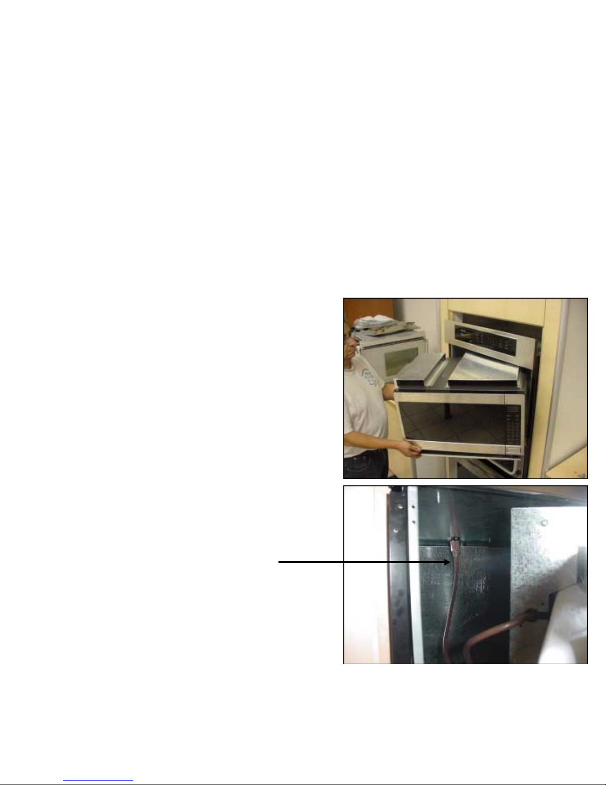
Microwave Section…Removal
Microwave Section…
Microwave Section…
Removal
Removal
➤
➤
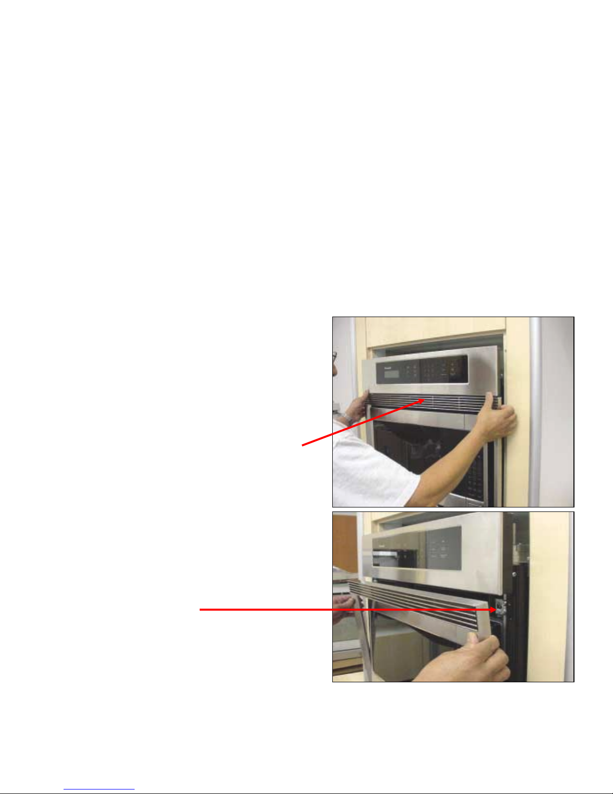
To gain access to the
To gain access to the
microwave section
microwave section
➤
➤
Remove vent frame from
Remove vent frame from
around the microwave
around the microwave
unit. This frame is a one
unit. This frame is a one
piece construction
piece construction
➤
➤
Grasp the frame and pull
Grasp the frame and pull
the ball studs from the
the ball studs from the
spring catches
spring catches
15
15
16
16
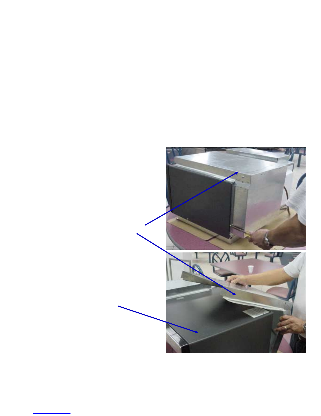
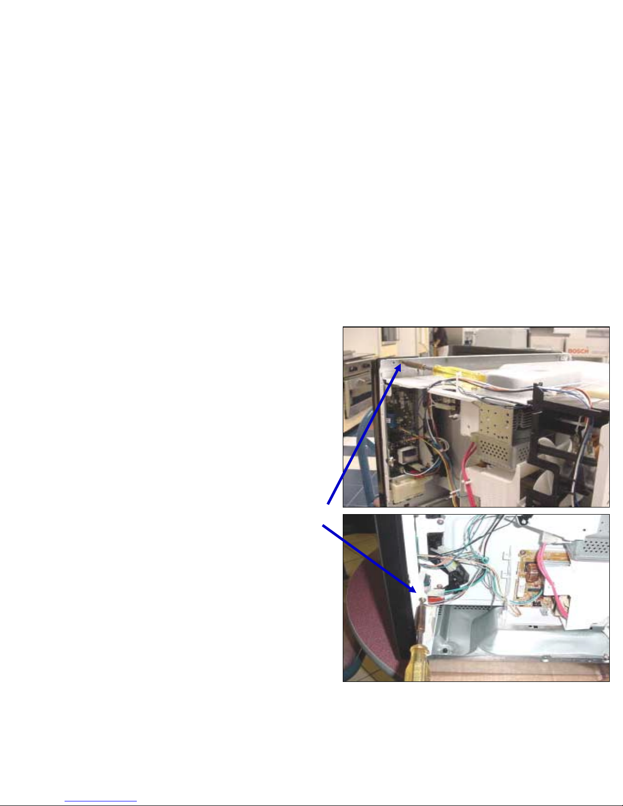
Microwave Section…Removal
Microwave Section…
Microwave Section…
Removal
Removal
➤
➤
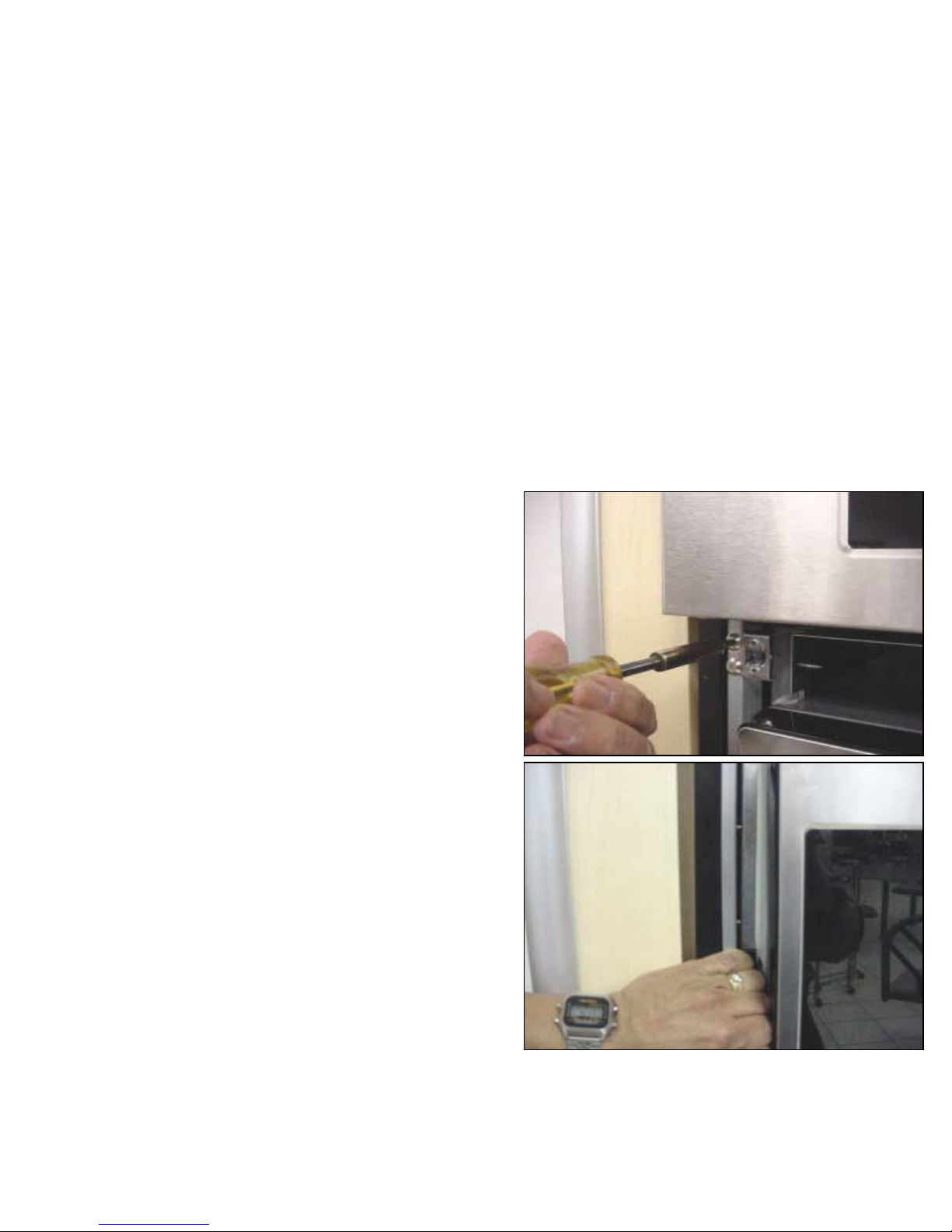
Remove the 2 screws
Remove the 2 screws
which hold the microwave
which hold the microwave
base to the oven housing
base to the oven housing
➤
➤
Remove the spring catches,
Remove the spring catches,
which are secured with
which are secured with
two screws
two screws
➤
➤
Bow out the side of outer
Bow out the side of outer
frame slightly to allow the
frame slightly to allow the
section to slide out easily
section to slide out easily
16
16
17
17
Microwave Section…Removal
Microwave Section…
Microwave Section…
Removal
Removal
➤
➤
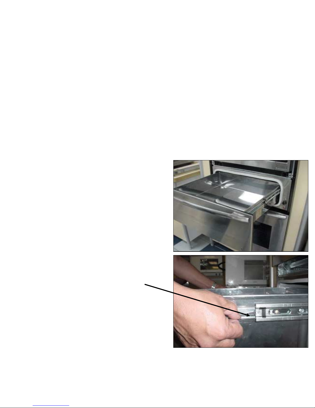
Before removing
Before removing
section, remove
section, remove
warming drawer to
warming drawer to
avoid scratching
avoid scratching
➤
➤
Slide tabs on both
Slide tabs on both
sides of rails and
sides of rails and
drawer will pull out
drawer will pull out
17
17
18
18
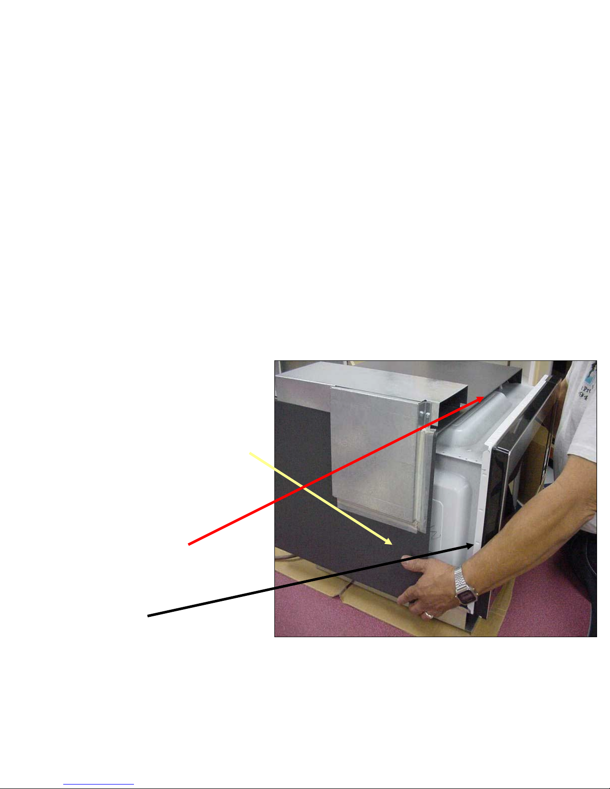
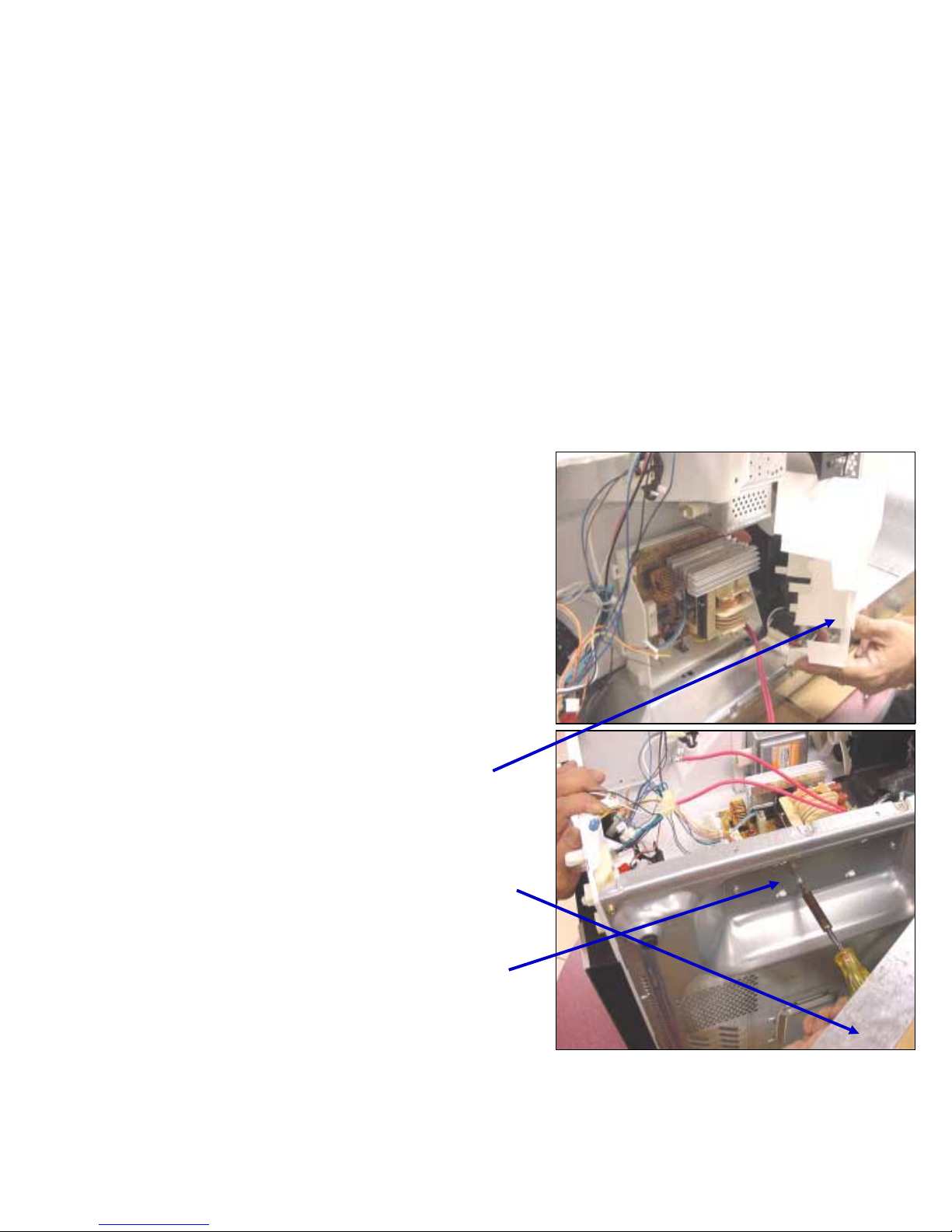
Microwave Section…Removal
Microwave Section…
Microwave Section…
Removal
Removal
➤
➤
Slide section part way
Slide section part way
out leaving the right
out leaving the right
rear corner still inside
rear corner still inside
housing
housing
➤
➤
While holding front of
While holding front of
unit reach inside and
unit reach inside and
unplug the section
unplug the section
from the receptacle
from the receptacle
18
18

19
19
Microwave Section …Removal
Microwave Section …
Microwave Section …
Removal
Removal
➤
➤
Section can now be
Section can now be
removed completely
removed completely
and set down on a
and set down on a
solid surface
solid surface
➤
➤
Note the exhaust duct
Note the exhaust duct
covers on the top of
covers on the top of
the microwave cover
the microwave cover
19
19
20
20
Microwave Section…Access Duct Cover
Microwave Section…
Microwave Section…
Access Duct Cover
Access Duct Cover
➤
➤
To gain access to the
To gain access to the
microwave components
microwave components
the duct exhaust parts
the duct exhaust parts
must first be removed
must first be removed
from the microwave
from the microwave
cover
cover
➤
➤
The microwave cover can
The microwave cover can
then be removed
then be removed
20
20
21
21
Microwave Section…Access Outer Cover
Microwave Section…
Microwave Section…
Access Outer Cover
Access Outer Cover
➤
➤
After removing the
After removing the
screws from the sides
screws from the sides
and rear, the cover slides
and rear, the cover slides
away from the front
away from the front
allowing access to most
allowing access to most
of the components.
of the components.
➤
➤
Note the groove on the
Note the groove on the
cover and the tab on the
cover and the tab on the
front frame
front frame
22
22
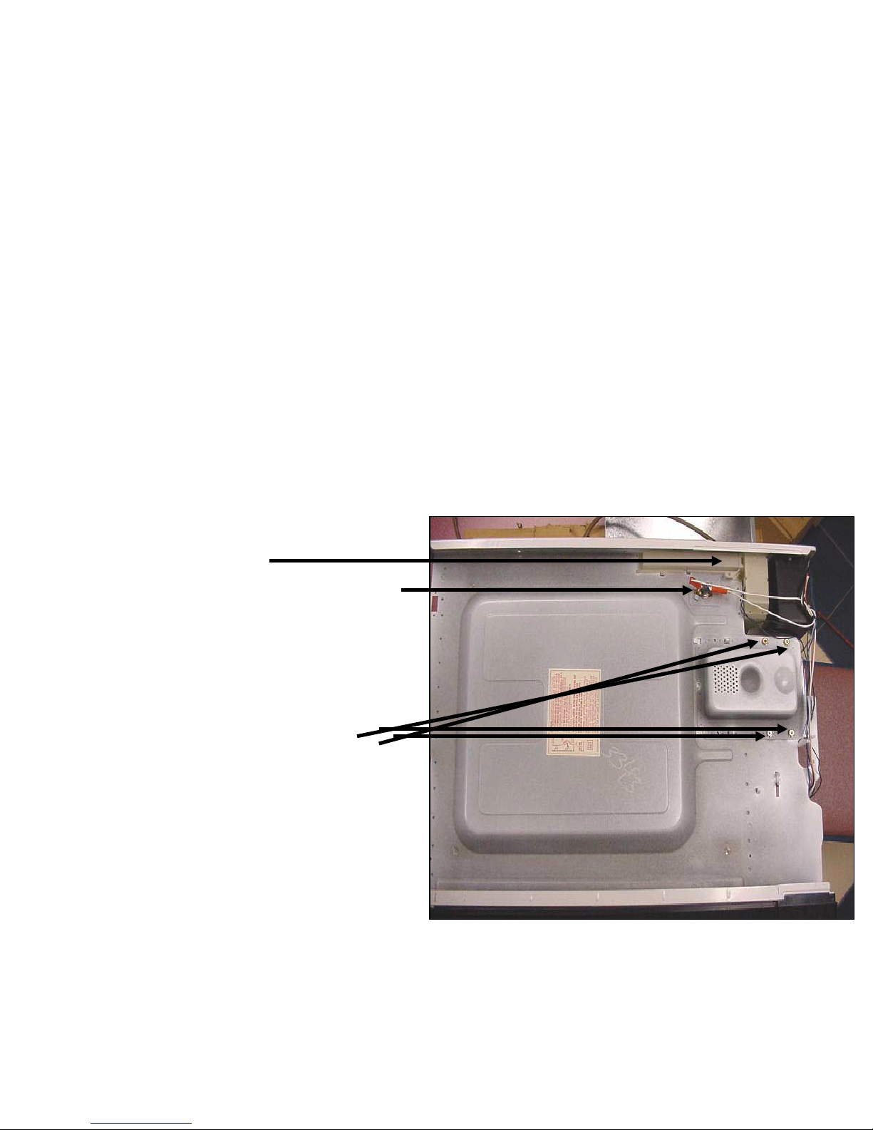
Component Description & Access…Mag
tube & Mag tube thermal cutout
Component Description &
Component Description &
Access
Access
…
…
Mag
Mag
tube & Mag tube thermal cutout
tube & Mag tube thermal cutout
➤
➤
Steam Sensor Location
Steam Sensor Location
( inside cover)
( inside cover)
➤
➤
Mag-tube thermal cutout
Mag-tube thermal cutout
N/C opens at 221 deg. F
N/C opens at 221 deg. F
➤
➤
Mag tube is secured with
Mag tube is secured with
four screws. Across
four screws. Across
filament terminals should
filament terminals should
read 1 Ohm or less.
read 1 Ohm or less.
Between each terminal
Between each terminal
and ground should be
and ground should be
open
open
23
23
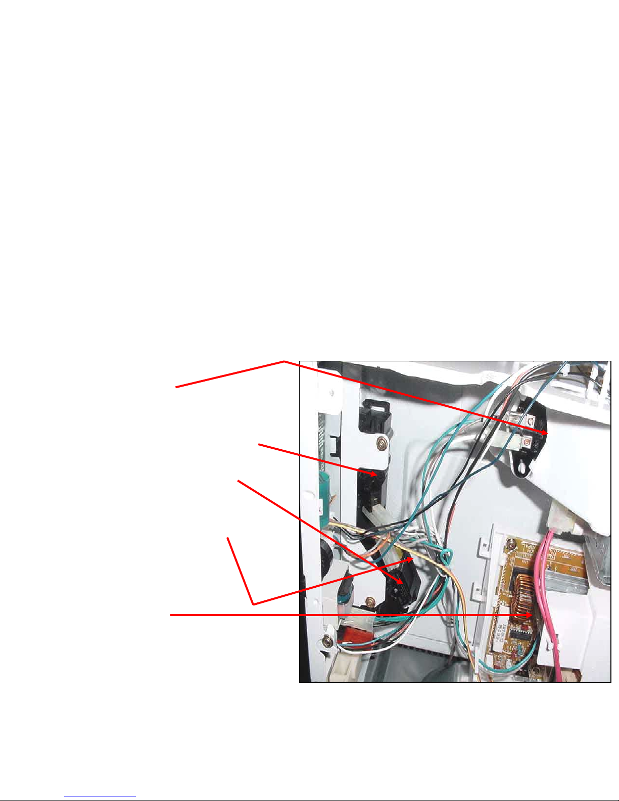
Component Description & Access….
Door switches and lamp assembly
Component Description &
Component Description &
Access….
Access….
Door switches and lamp assembly
Door switches and lamp assembly
➤
➤
Lamp assembly
Lamp assembly
lamp is 20watts 120V
lamp is 20watts 120V
➤
➤
Primary latch switch N/O
Primary latch switch N/O
➤
➤
Secondary latch switch N/O
Secondary latch switch N/O
& is the outside switch
& is the outside switch
➤
➤
Monitor or short switch N/C
Monitor or short switch N/C
& is the inside switch
& is the inside switch
➤
➤
Inverter board
Inverter board
23
23
24
24
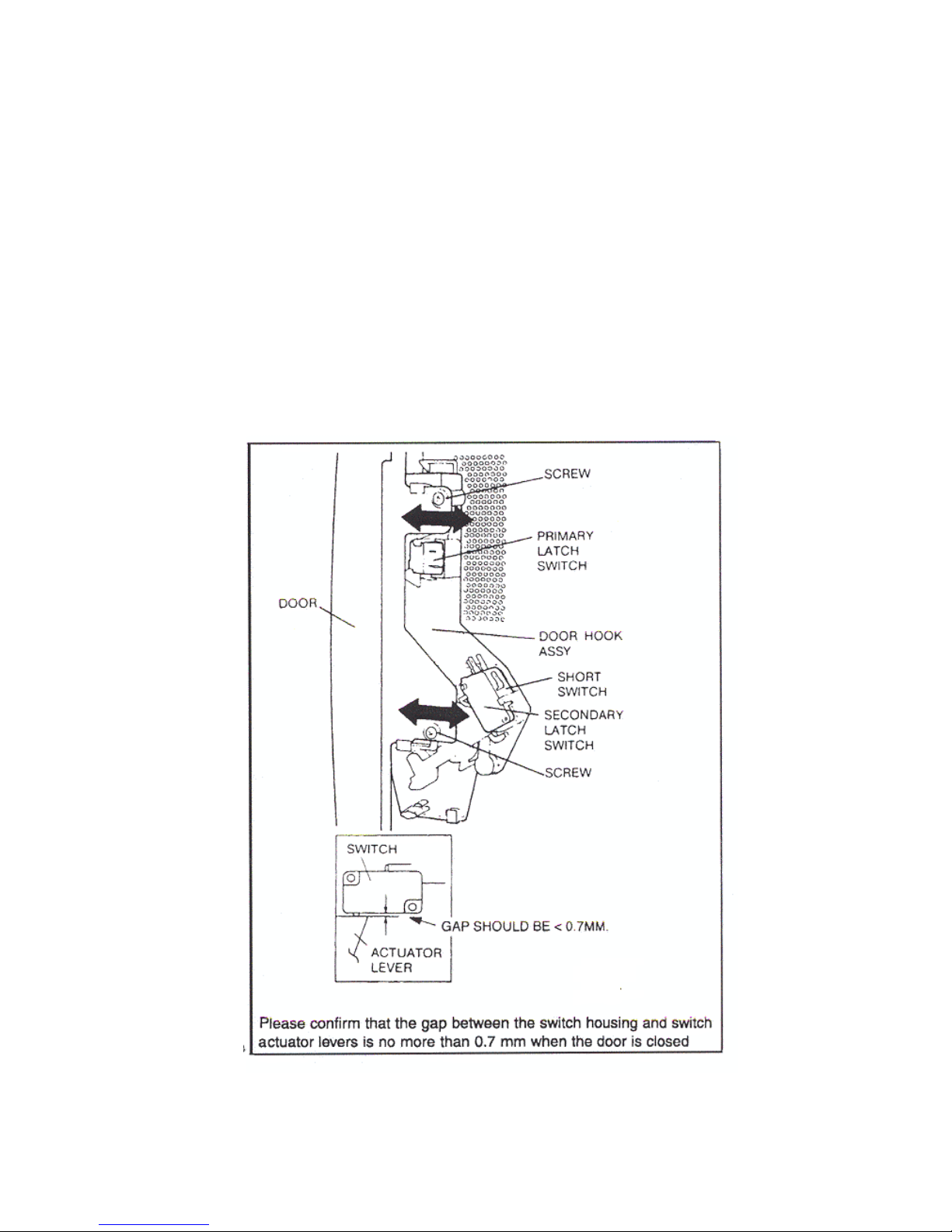
Microwave Section….
Microwave Section….
Door Switch Locations & Adjustments
Door Switch Locations & Adjustments
25
25
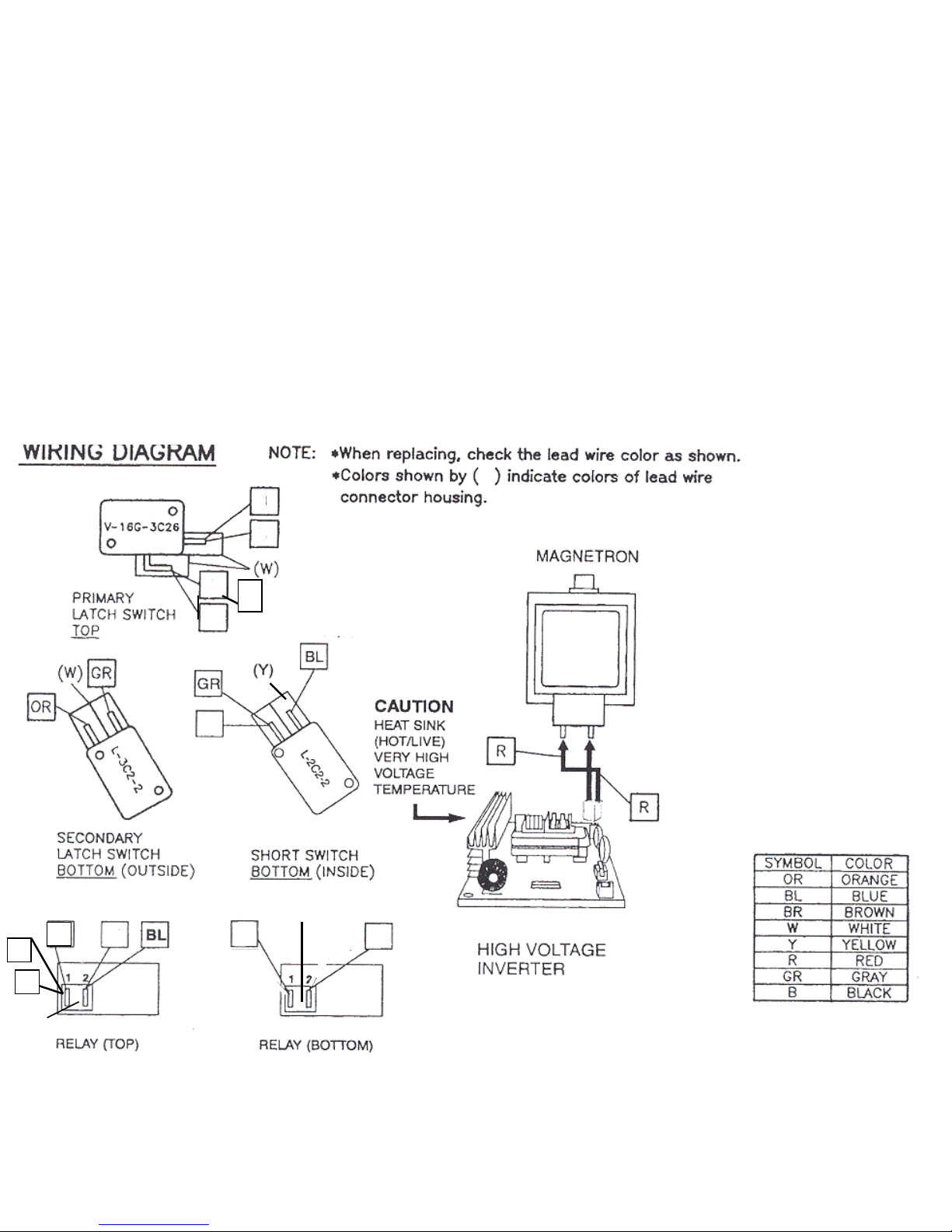
SMW Microwave switch & relay wiring
SMW Microwave switch & relay wiring
N/O
N/O
Switch
Switch
N/C
N/C
Switch
Switch
N/O Switch
N/O Switch
CCN/O
N/O
W
W
W
W
B
B
B
B
B
B
GR
GR
GR
GR
W
W
W
W
BL
BL
B
B
OR
OR
25
25
(R)
(R)
(W)
(W)
BR
BR
(W) White (Y) Yellow (R) Red
(W) White (Y) Yellow (R) Red
26
26
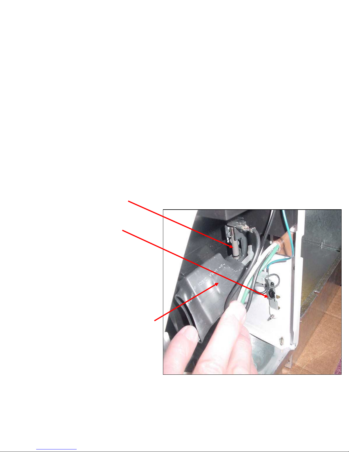
Component Description &
Access….Fuse Temp. Sensor & Noise Filter
Component Description &
Component Description &
Access….Fuse Temp. Sensor & Noise Filter
Access….Fuse Temp. Sensor & Noise Filter
➤
➤
Fuse is rated at 18 amps
Fuse is rated at 18 amps
( regular cartridge fuse )
( regular cartridge fuse )
➤
➤
Temperature sensor
Temperature sensor
measures 40,000 Ohms to
measures 40,000 Ohms to
ground If excessive cabinet
ground If excessive cabinet
temperature is detected
temperature is detected
cooling fan will turn on
cooling fan will turn on
automatically until temp.
automatically until temp.
drops
drops
(part # 35-00-778)
(part # 35-00-778)
➤
➤
Noise filter is across hot and
Noise filter is across hot and
neutral incoming supply
neutral incoming supply
(part #
(part #
35-00-786)
35-00-786)
(Part # 35-00-787)
(Part # 35-00-787)
27
27
Component Description & Access…
Microwave Touch Control Door Assembly
Component Description &
Component Description &
Access…
Access…
Microwave Touch Control Door Assembly
Microwave Touch Control Door Assembly
➤
➤
Before removing door
Before removing door
assembly
assembly
disconnect the four
disconnect the four
plug connectors, the ribbon
plug connectors, the ribbon
connector and the two relay
connector and the two relay
plugs.
plugs.
(all connection plugs are color
(all connection plugs are color
coded so that they can’t be mis-wired)
coded so that they can’t be mis-wired)
➤
➤
To remove assembly
To remove assembly
remove
remove
the two screws from the top
the two screws from the top
and the single screw from the
and the single screw from the
side of the frame
side of the frame
➤
➤
Door assembly
Door assembly
will then lift
will then lift
up and out of the slots in the
up and out of the slots in the
frame
frame
27
27
28
28
Component Description &
Access….High Voltage Inverter
Component Description &
Component Description &
Access….High Voltage Inverter
Access….High Voltage Inverter
➤
➤
To gain access to the Inverter
To gain access to the Inverter
Power Supply Board
Power Supply Board
disconnect the mag tube HV
disconnect the mag tube HV
wires
wires
➤
➤
Unsnap the plastic air guide
Unsnap the plastic air guide
from the tabs
from the tabs
➤
➤
To remove board remove m/w
To remove board remove m/w
pan (4 screws at the corners &
pan (4 screws at the corners &
3 across the rear) then the 3
3 across the rear) then the 3
screws which secure the board
screws which secure the board
28
28
29
29
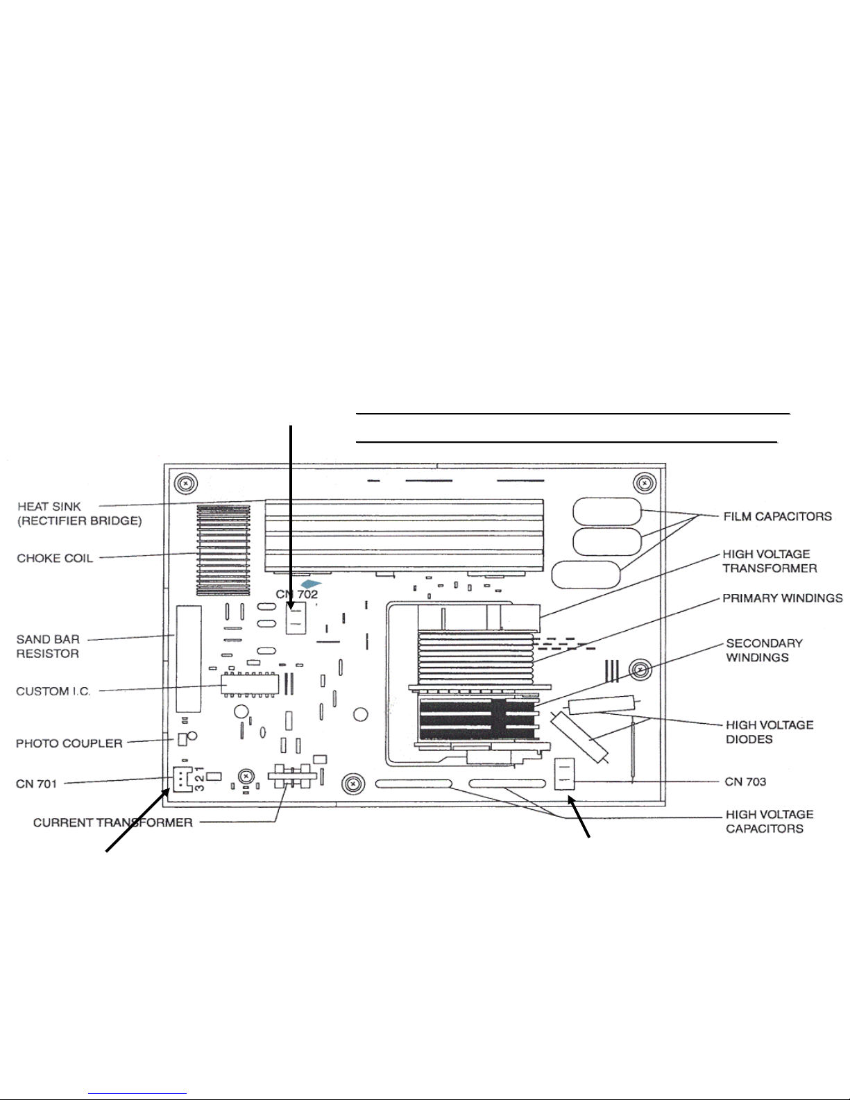
Component Description &
Access…High Voltage Inverter Terminals
Component Description &
Component Description &
Access…High Voltage Inverter Terminals
Access…High Voltage Inverter Terminals
➤
➤
CN702
CN702
…120VAC
…120VAC
input to transformer
input to transformer
➤
➤
CN701
CN701
…Signal
…Signal
voltage from DPC
voltage from DPC
circuit (3 wire plug)
circuit (3 wire plug)
Voltage varies from 0
Voltage varies from 0
volts to 2.7VAC for
volts to 2.7VAC for
variable power levels
variable power levels
➤
➤
CN703
CN703
…4000VDC
…4000VDC
output to mag tube
output to mag tube
30
30
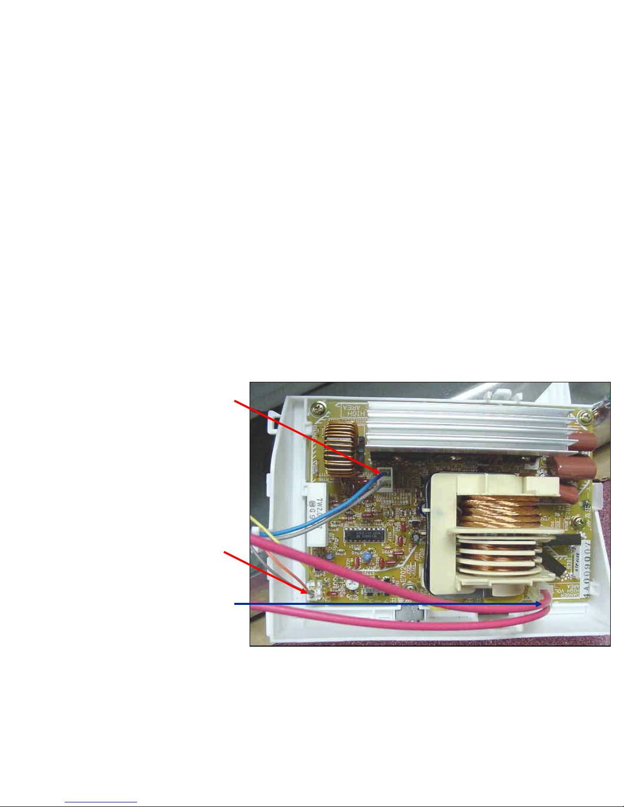
Microwave Section….Inverter Power supply HV Area
Microwave Section….Inverter Power supply HV Area
Low Voltage Input from DPC 0-2.7
Low Voltage Input from DPC 0-2.7
VAC ( see table on page 30)
VAC ( see table on page 30)
120 VAC Input
120 VAC Input
High Voltage 4000 VDC
High Voltage 4000 VDC
Output to Mag Tube
Output to Mag Tube
Note Do not attempt to repair this inverter
Note Do not attempt to repair this inverter
board. Replace as a complete asse mbly
board. Replace as a complete asse mbly
Part # 35-00-789
Part # 35-00-789
 Loading...