

Thermador SMW272 B, SMW272S, SMW272P, SMW272W Service Manual
Service Manual
STOP
COOK
2
TIME
TIMER 1 TIMER 2
CLOCK
1
TIME
4
OVEN
LIGHT
7
56
8
0
OFF
BAKE
3
SELF
BROIL
CLEAN
CONVECTIO
CONVECTION
9
ROAST
SENSOR
SENSOR
COOK
REHEAT
POWER
POP
LEVEL
CORN
123
4
5 6
708
9
CLOCK
TIMER
MORE
QUICK
FUNCTION
/LESS
MIN
KEY
SERVING
KEEP
TURBO
/WEIGHT
WARM
DEFROST
STOP/RESET START
Thermador® Built-In Oven
SMW272 B, SMW272S, SMW272W, SMW272P
for
Models:

SMW Oven
Table of Contents
Manual introduction
and Safety Precautions........................... 1 – 2
Microwave Oven Section: Specifications ....3
Removal from Cabinet...................................................4
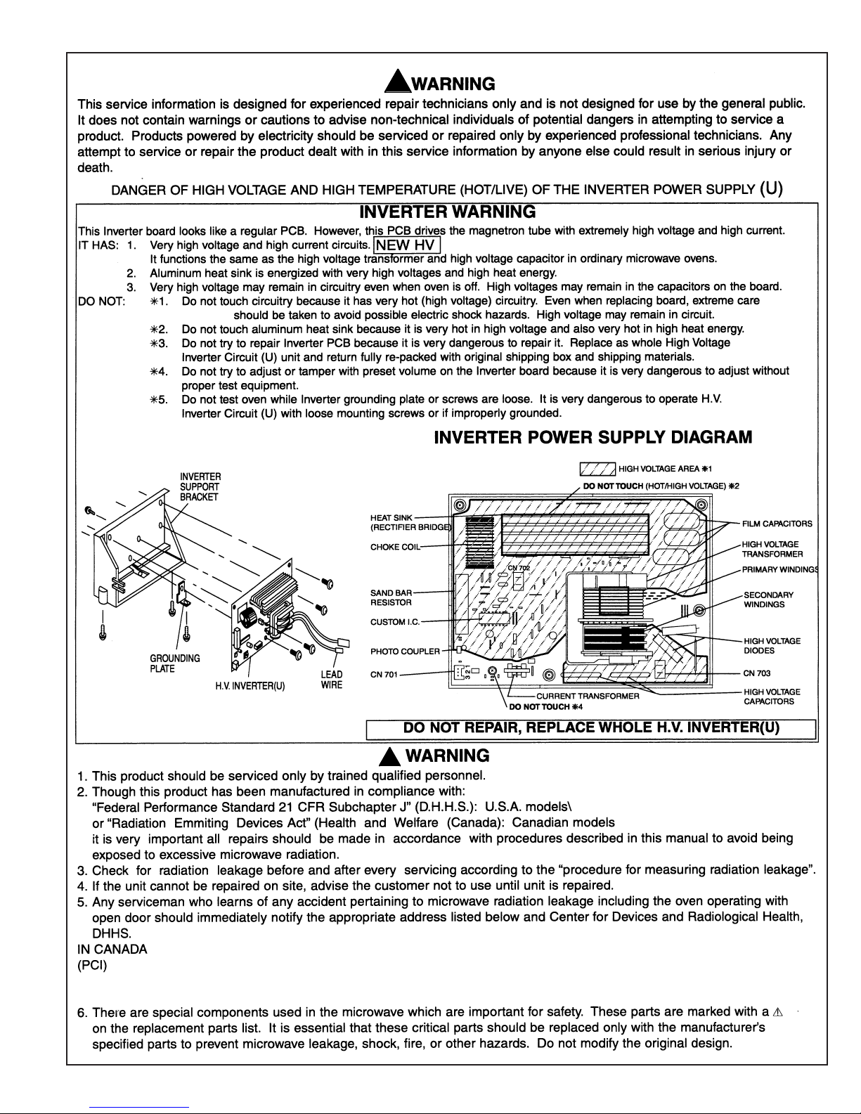
Warning: Danbger of High Voltage ..............................5
Microwave Control Panel..............................................6
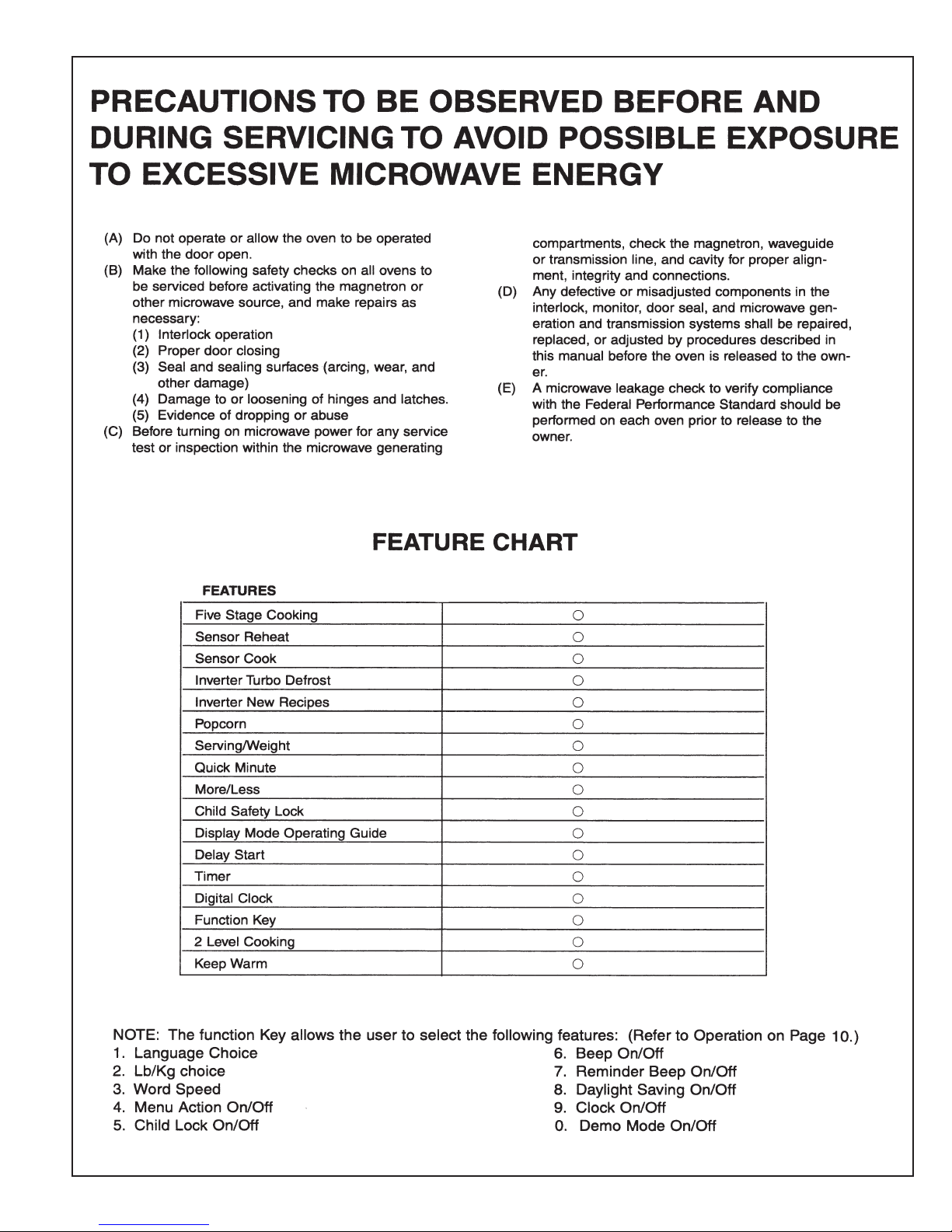
Precautions to Avoid Exposure to
Excessive Miocrowave Energy................................. 7
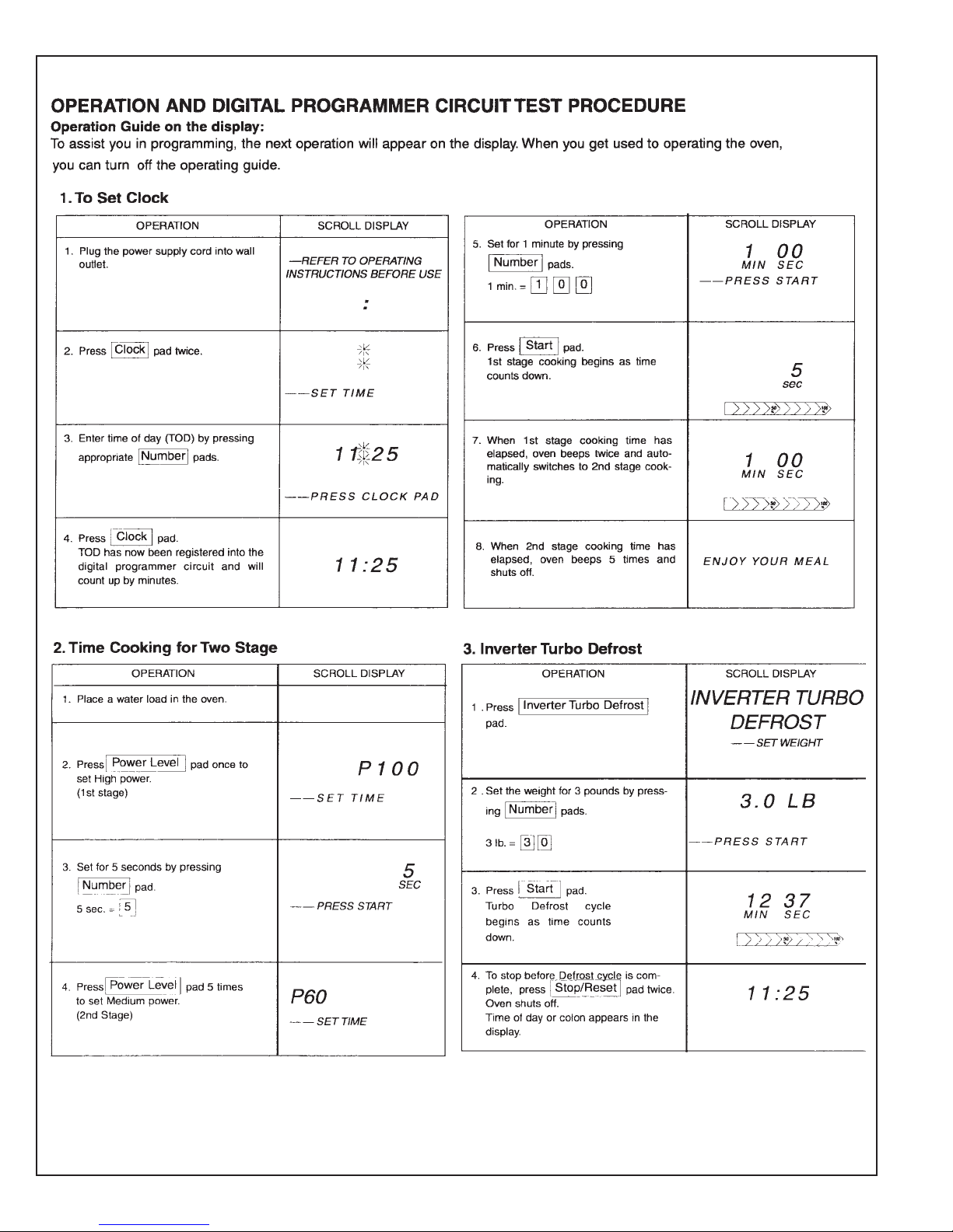
Circuit Test Procedure ............................................8 – 9
to Use Function Pad .....................................................10
Schematic Diagrams......................................................11
Description of Operating Sequence .........................12
Cautions to be Observed
When T roubleshooting............................................14
Disassembly and Parts Replacement Procedure....16
Component T est Procedur e........................................18
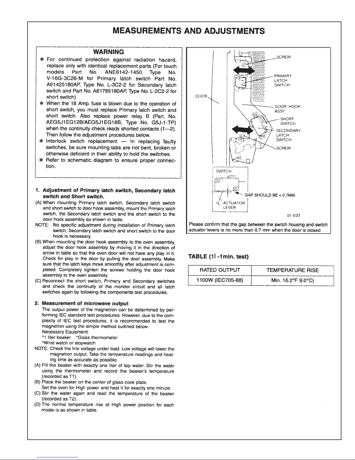
Measurements and Adjustments ................................20
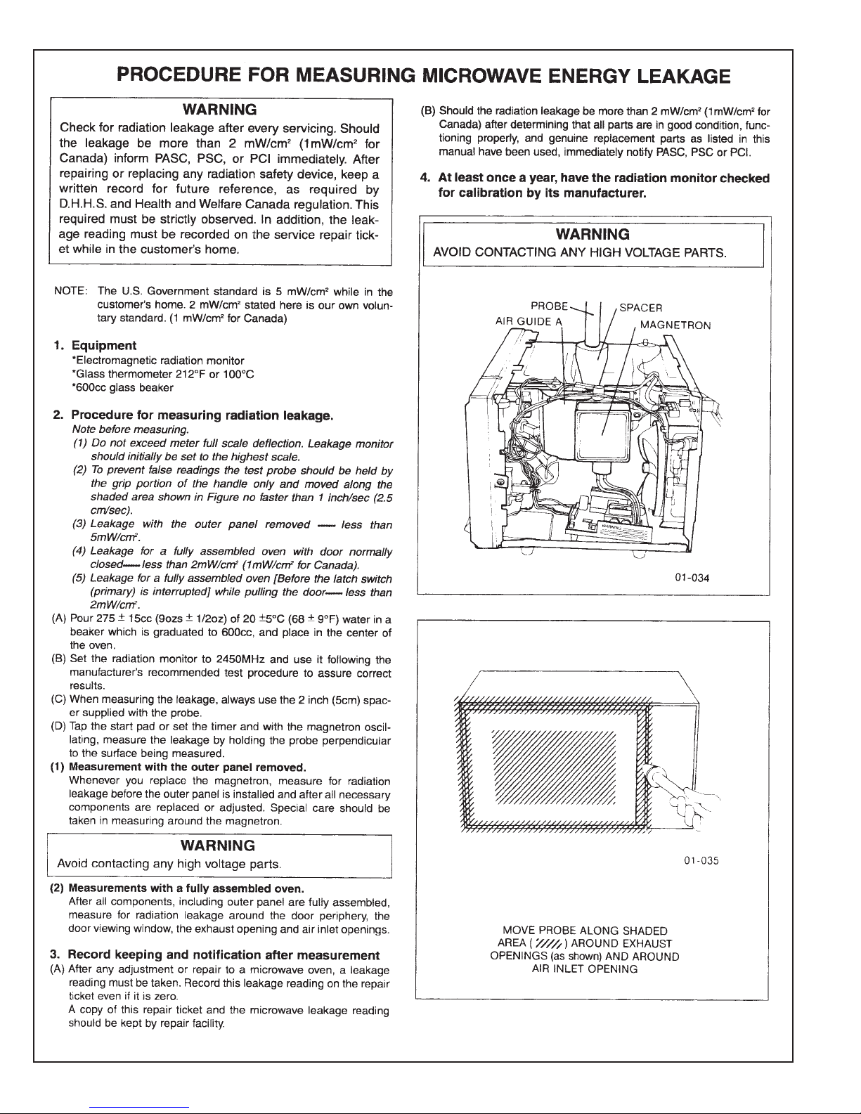
Procedure for Measuring
Microwave Energy Leakage ....................................21
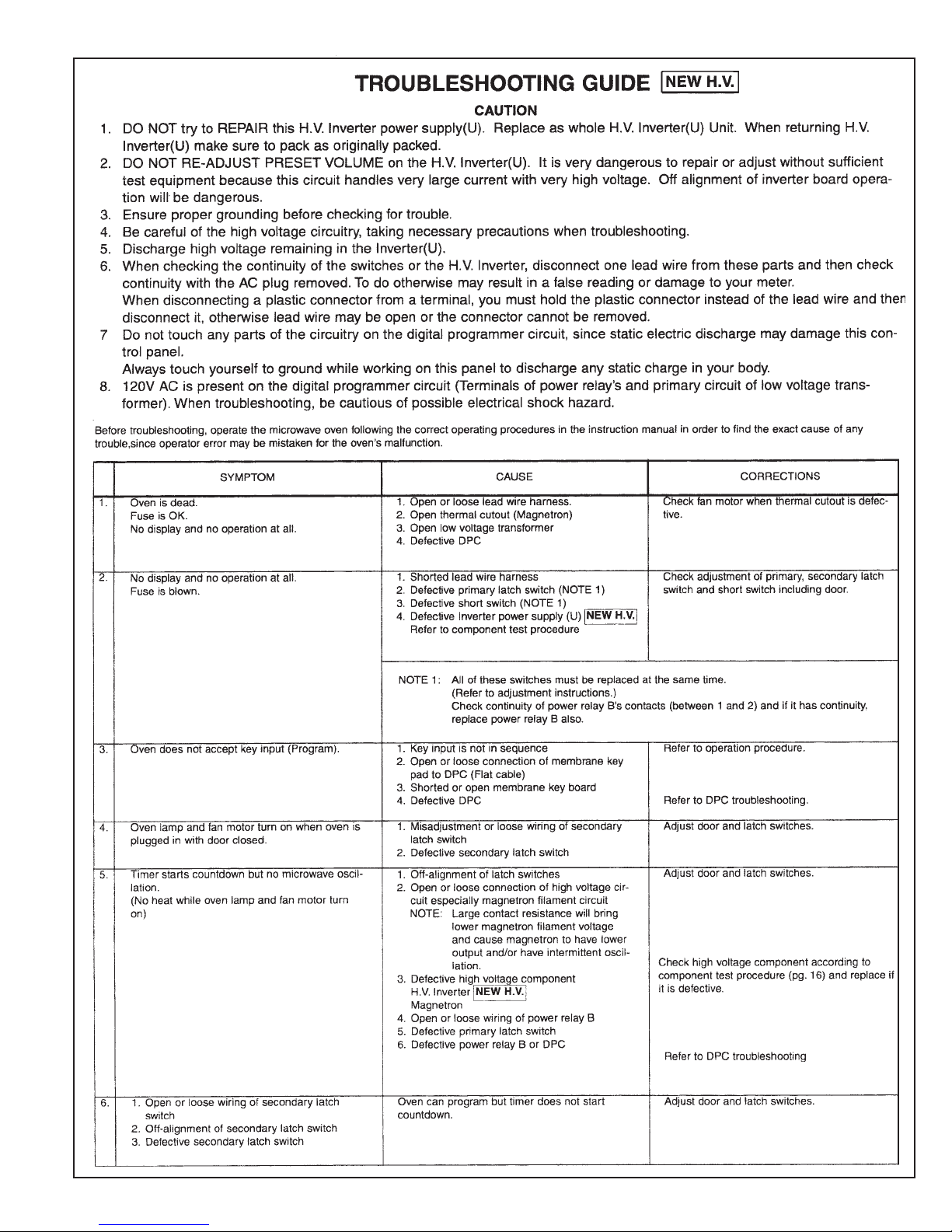
Troubleshooting Guide ..........................................22-25
Parts List of Digital Programmer Circuit &
Schematic Diagrams...........................................26-29
Removing the Oven Temperature Sensor ...............40
Removing the Convection Bake Element ................41
Removing A Convection Fan Motor .........................42
Removing A Halogen Lamp Holder ..........................44
Removing the Control Panel and Display Head.....46
Removing the Oven Light Switch,
The Oven Door Latch Assembly ,
The Hi-Temp Cutout...............................................48
Removing the Relay Board..........................................50
Lower Oven Relay Board ............................................51
Removing the Air Switches .........................................52
Removing the Blower...................................................54
Removing the Lamp Transformer &
the Lower Oven Stalled Fan Relay .......................56
Removing the Lower Oven Door.............................57
Removing the Oven Door Gasket............................58
Removing the Oven Door Components.................59
Removing the “S” Oven Module................................60
Troubleshooting.............................................................61
Connectors.....................................................................65
Convection Oven Relay Board...................................68
Oven Relay Board Matrix............................................69
Error Code Messages...................................................71
Warming Drawer Section..........................31
Replace thermostat or On/off Switch......................32
Replace Heating Element:............................................33
Replace Liner Slides:.....................................................33
Warming Drawer Wiring Diagram ............................34
Lower Oven Section ...................................35
Symbols You Will See in the Manual..........................36
Serial Number/Data Sticker Location ......................37
Removing the Bake and Broil Elements, Catalyst ..38
Electronic Oven Control Test Modes.......................72
Sequence of Operation................................................75
Lower Oven....................................................................75
Bake Cycle — Bake Preheat and Bake Mode .........75
Broil Cycle — Broil Preheat and Broil Mode.........76
Convection Cycle – Convection Preheat
and Convection Mode.............................................77
Convection Roast Preheat..........................................78
Convection Roast Cycle..............................................79
Self-Clean Cycle — Preheat below 840˚.................80
Self-Clean Cycle.............................................................81
Lower Oven Wiring Diagram
and Schematic................Foldout, inside back cover
Page 2

SMW Oven Service ManualIntroduction
SMW SERVICE MANU AL
This manual contains information that is necessary for servicing the Thermador® built-in
electric ovens, models:
SMW272B, SMW272W, SMW272S, SMW272P
This manual, as well as the information contained in it, is designed to be used
only by qualified authorized Thermador service personnel, familiar with and
knowlegable of pr oper safety and servicing procedures and possessing high quality
testing equipment associated with Micro wav e, gas and electrical appliance repiar.
Thermador recommends that customers DO NOT SERVICE THEIR OWN
UNITS, due to the complexity and the risk of high-voltage electrical shock.
All individuals who attempt repairs by improper means or adjustment subject
themselves and others to the risk of serious and fatal injury.
Use only genuine Thermador approved fdactory replacement components.
The information is organized to help the servicer easily find what is needed to repair the unit.
SAFETY PRECAUTIONS
PRECAUTIONS TO BE OBSERVED BEFORE AND DURING SERVICING TO
AVOID POSSIBLE EXPOSURE TO EXCESSIVE MICROWAVE ENERGY:
A. Do not operate or allow the oven to be operated with the door open.
B. Make the following safety checks on all ovens to be serviced before activating the magnetron or
other microwave source, and make repairs as necessary.
(1) Interlock operation.
(2) Proper door closing.
(3) Seal and sealing surfaces (arcing, wear, and other damage).
(4) Damage to or loosening of hinges and latches.
(5) Evidence of dropping or abuse.
C. Before turning on microwave power for any service test or inspection within the microwave gener-
ating compartments, check the magnetron, wave guide or transmission line, and cavity for proper
alignment, integrity, and connections.
D. Any defective or misadjusted components in the interlock, monitor, door seal and microwave gen-
eration and transmission systems shall be repaired, replaced, or adjusted by pr ocedur es described in
this manual before the oven is released to the owner.
E. A microwave leakage check to verify compliance with the Federal performance standard should be
performed on each oven prior to release to the owner.
F. Operate the oven from a properly grounded AC outlet capable of supplying 120/240 or a 120/208
volt, 60Hz.
Page 1
SMW Oven Service ManualIntroduction
708
9
4
5 6
123
SENSOR
REHEAT
SENSOR
COOK
POWER
LEVEL
POP
CORN
TIMER
CLOCK
MORE
/LESS
QUICK
MIN
FUNCTION
KEY
SERVING
/WEIGHT
KEEP
WARM
TURBO
DEFROST
STOP/RESET START
INTRODUCTION
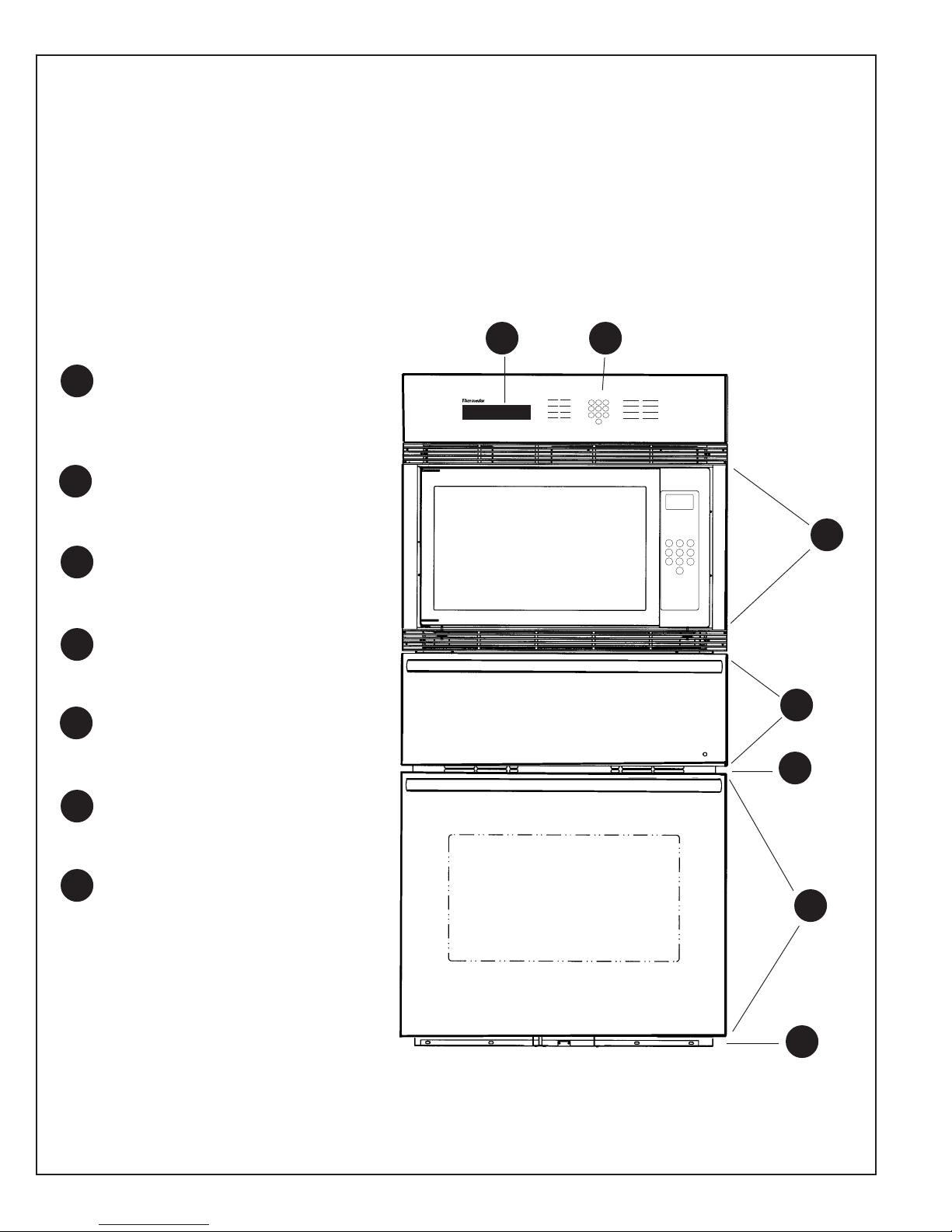
Model SMW272
Model SMW272 is desigmed with modular construction which makes it easier to service. The SMW Oven
has a microwave section that is enclosed in the structure. The microwave section can be pulled out to service
additionally, it has a warming drawer built into the structure below the microwave section. It does not need
to be removed for service. All service can be performed from the front. The lower oven is an “S” oven with
single “S” oven controls.
1 2
1 Time of Day Clock and Lower Oven
1
Display Window
2
2 Touch Pads for Lower Oven
COOK
TIME
TIMER 1 TIMER 2
CLOCK
STOP
2
1
TIME
56
4
OVEN
8
LIGHT
7
0
OFF
BAKE
3
SELF
BROIL
CLEAN
CONVECTION
CONVECTION
9
ROAST
3
3 Microwave Oven Section
4 Warming Drawer Section
4
5
5 Oven Cooling Vents
6 Lower Convection Oven Section
6
7
7 Lower Oven Exhaust Vent
3
4
5
6
7
Page 2
SMW Oven Service ManualMicrowave Oven Section
Micr o wav e Oven Section
STOP
COOK
TIME
TIMER 1 TIMER 2
CLOCK
1
2
TIME
OVEN
LIGHT
3
56
4
9
8
7
0
CONVECTION
OFF
BAKE
SELF
BROIL
CLEAN
CONVECTION
ROAST
SENSOR
SENSOR
COOK
REHEAT
POWER
POP
LEVEL
CORN
123
4
5 6
708
9
CLOCK
TIMER
MORE
QUICK
FUNCTION
/LESS
MIN
KEY
SERVING
KEEP
TURBO
/WEIGHT
WARM
DEFROST
STOP/RESET START
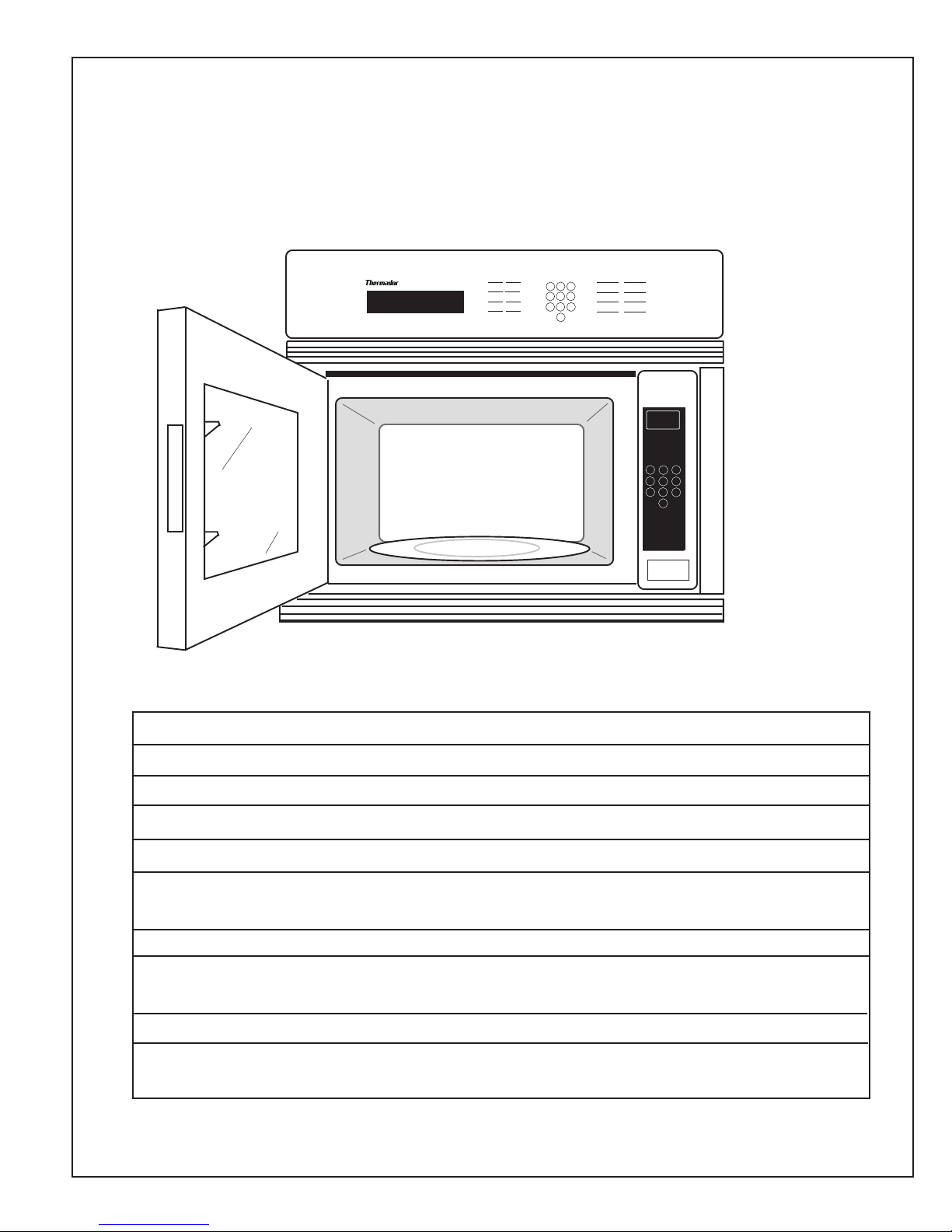
Specifications
Models:
Power Source: 120 VAC Single Phase, 60 Hz
Power Requirements: 1420W (12.1A)
Output: 1100W
Micro wave F requency: 2,450MHz
Timer: 30 min. /stage (HIGH Power) – 5 Stage Maximum
99 min. 99 sec. /stage (Other Power Levels) 3 Stage Maximum
Oven Cavity Size: 2.1 cu. ft.
Inside Dimensions: 18-7/16" (W) X 181/2" (D) X 1011/16" (H)
(W x D x H) 469mm (W) X 470mm (D) X 271 mm (H)
Weight: 40 Ibs/18.1 kg
Inverter Power Supply Output power: IEC705-88 Test procedure
Specifications subject to change without notice
Page 3
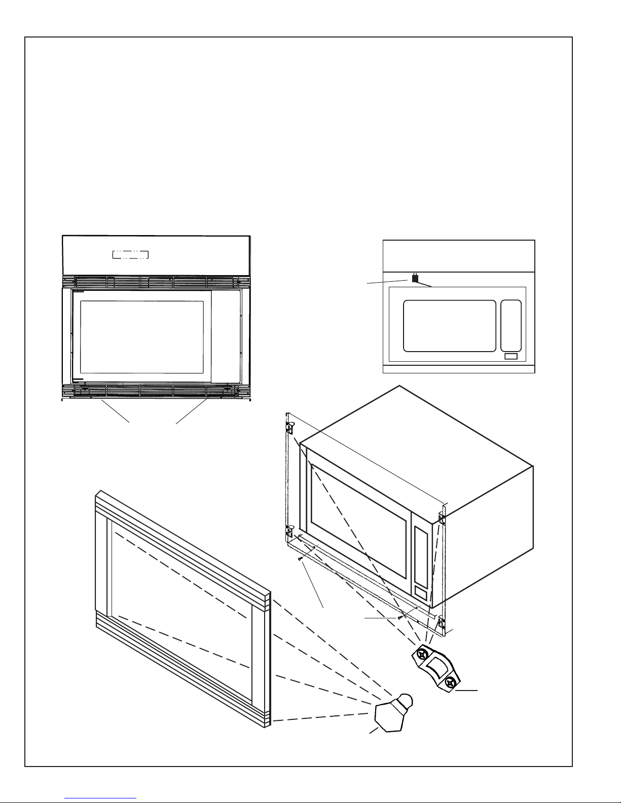
To remo ve microwave section from cabinet:
1) Using both hands, pull the sides of the frame forward and unsnap the posts on both sides
of the frame from the catches on the enclosure (See Illustrations, below).
2) Remove the two screws holding the microwave section in the enclosure.
3) Pull the microwave section out of the cabinet half way.
4) Disconnect the electrical cord (Top left, back corner) and remove the microwave section
all the way out of the enclosure.
Electrical
Cord
(Step 4)
SMW Oven Service ManualMicrowave Oven Section
Screws
(Step 2)
Visible after Frame removal
➞
Frame
removal
Pull with both hands;
unsnap posts at each corner
(Step 1).
➞
Screws
(Step 2)
Post (Step 1)
➞
Catch
(Step 1)
Page 4
SMW Oven Service ManualMicrowave Oven Section
!
Thermador Customer Service
5551 McFadden Ave.
Huntington Beach, CA 92646
800/735-4328
!
Page 5
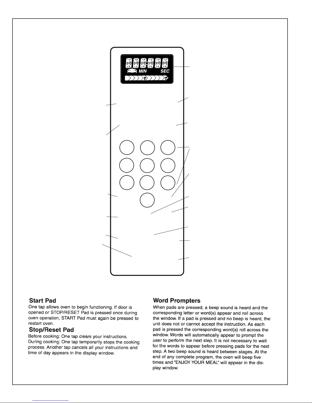
Microwa v e Contr ol P anel
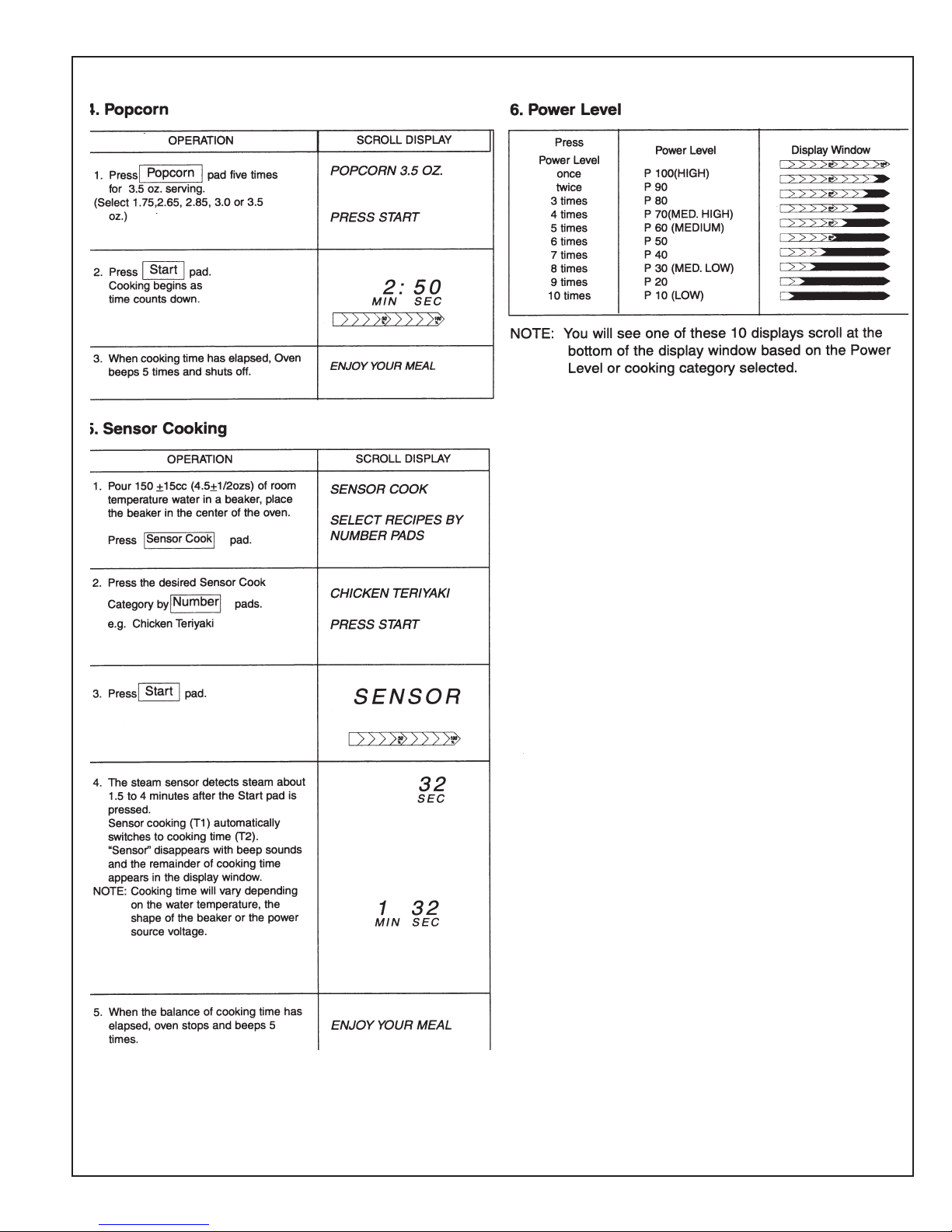
Beep Sound
When a pad is pressed correctly, a beep
will be heard. If a pad is pressed and no
beep is heard, the unit did not or cannot
accept the instruction. The oven will
beep twice between programmed
stages. At the end of any complete
program, the oven will beep 5 times.
Sensor Reheat Pad
Automatically reheats.
Three different categories.
Power Level Pad
Manually changes Microwave power.
SENSOR
REHEAT
POWER
LEVEL
1
SMW Oven Service ManualMicrowave Oven Section
Display Windo w
Sensor Cook Pad
SENSOR
COOK
POP
CORN
2
3
Automatically calculates cooking time for
six different items.
Popcorn Pad
Automatically timed by weight.
Number Pads
Timer Pad
Counts down and signals end
time. Can be used for delay or
stand time.
More/Less Pad
Increases or decreases
cooking time for Sensor
Cook or Sensor Reheat.
Stop/Reset Pad
Before cooking: One tap clears your
instruction. During cooking: one tap
temporarily stops to cooking process.
Another tap cancels all your instructions
and time of day or colon appears on the
Display Window .
4
7
TIMER
MORE
/LESS
SERVING
/WEIGHT
STOP/RESET START
5 6
8
0
QUICK
MIN
KEEP
WARM
CLOCK
FUNCTION
KEY
TURBO
DEFROST
Time of Day Clock Pad
9
Quick Minute Pad
Adds or sets time in 1 minute
increments, up to 10 minutes.
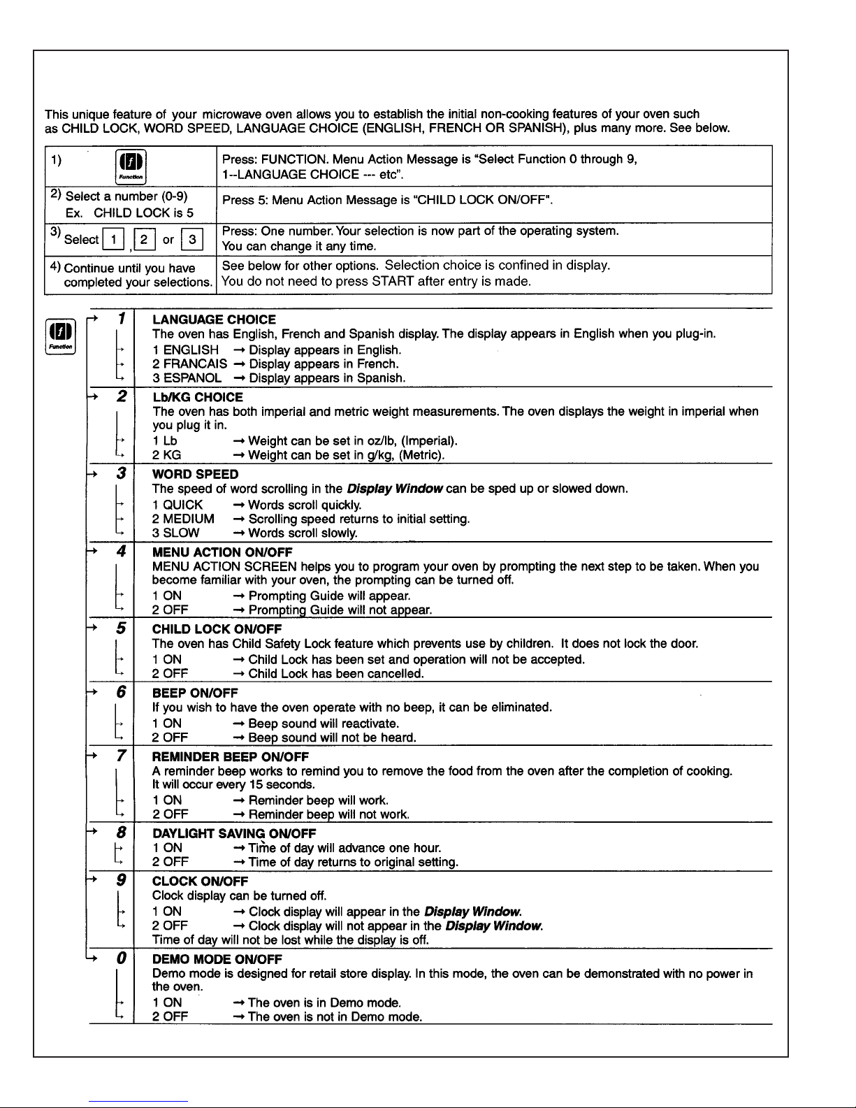
Function Key Pad
Selects the noncooking features,
i.e. Child Lock, etc.
Keep W arm Pad
Three different foods can be kept
warm for 30 minutes after cooking.
Turbo Defrost
Defrosts by weight.
Start Pad
One tap allows oven to begin functioning.
If door is opened or Stop/Reset Pad is
pressed once during oven operation. Start
Pad must be pressed again to restart oven.
Page 6
SMW Oven Service ManualMicrowave Oven Section
Page 7
SMW Oven Service ManualMicrowave Oven Section
Page 8
SMW Oven Service ManualMicrowave Oven Section
Page 9
To Use Function P ad
SMW Oven Service ManualMicrowave Oven Section
Page 10
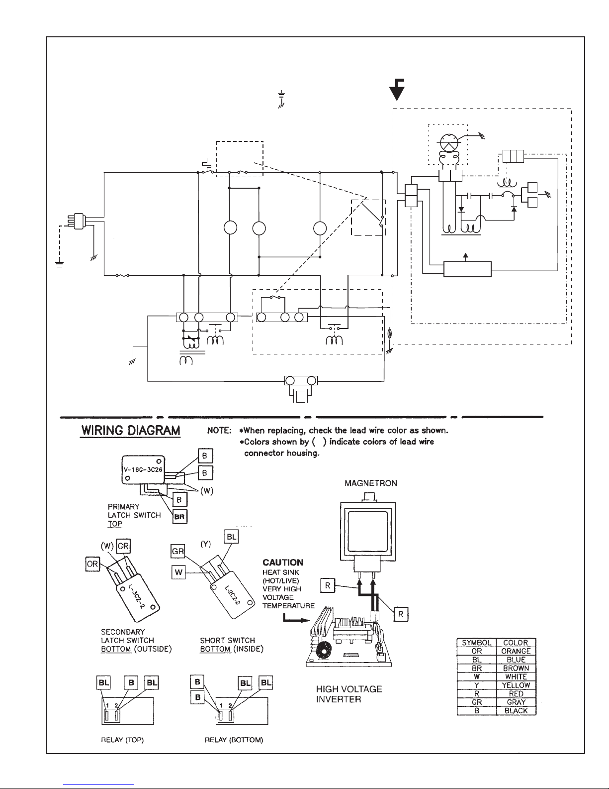
SCHMATIC DIAGRAM
SMW Oven Service ManualMicrowave Oven Section
AC120V
60Hz
BLACK WHITE
GREEN
FUSE
18A
NOTE: Door is closed.
THERMAL
CUTOUT
CN1
3
VARISTOR
DIGITAL PROGRAMMER CIRCUIT
LOWVOLTAGE
TRANSFORMER
PRIMARY
LATCH
SWITCH
OVEN
LAMP
L
5
1
POWER
RELAY A
(RY2)
Unit is not operating.
Ground
Chassis
FAN
MOTOR
MF M
1
3
SECONDARY
LATCH
SWITCH
41
31
TURN
TABLE
MOTOR
STEAM SENSOR
SHORT
SWITCH
POWER
RELAY B
(RY1)
CAUTION:
HIGHVOLTAGE AREA
MAGNETRON
P0
CN702
CN703
}
INVERTER
P120
CN701
TEMP SENSOR
(THERMAL PROTECTOR)
CN701
E702
E701
INV P.C.B.
Page 11
SMW Oven Service ManualMicrowave Oven Section
Page 12
SMW Oven Service ManualMicrowave Oven Section
Page 13
SMW Oven Service ManualMicrowave Oven Section
Page 14
SMW Oven Service ManualMicrowave Oven Section
Page 15
SMW Oven Service ManualMicrowave Oven Section
DISASSEMBLY AND PARTS REPLACEMENT PROCEDURE
Page 16
SMW Oven Service ManualMicrowave Oven Section
Page 17
SMW Oven Service ManualMicrowave Oven Section
Page 18
SMW Oven Service ManualMicrowave Oven Section
Page 19
SMW Oven Service ManualMicrowave Oven Section
Page 20
SMW Oven Service ManualMicrowave Oven Section
Page 21
SMW Oven Service ManualMicrowave Oven Section
Page 22
SMW Oven Service ManualMicrowave Oven Section
(Page 19).
Page 23
SMW Oven Service ManualMicrowave Oven Section
Page 24
 Loading...