

Page 1
INSTALLATION
INSTRUCTIONS
F o r B u i l t - i n M i c r o w a v e O v e n s
Oven
Model
MBB
Built-In
Trim Kits
Models:
MT27B
MT30B
(Sold Separately)
Page 2
Please read this entire manual before proceeding
IMPORTANT:
INSTALLER: Please leave these Installation Instructions with this unit for the
OWNER: Please retain these instructions for future reference.
WARNING: Disconnect power at the breaker before installing.
Local codes vary. Installation, electrical connections, circuit breakers
and grounding must comply with all applicable codes. Save these
instructions for your local electrical inspector's use.
owner.
Table of Contents
Step 1: Unpacking ...................................3
Step 2: Cabinet Preparation .................... 4
Step 3: Electrical Installation.................... 5
Step 4: Installing the Trim Kit................... 5
Step 5: Installing the Microwave Oven.... 6
Page 2
Page 3
Step 1: Unpacking
A. Microwave Oven Model MBB
Open the box and carefully remove all fillers and packing material.
Your new Thermador microwave includes the following:
• Care & Use manual (1)
• Quick Guide (1)
• Warranty Card (1)
• Turn Table (1)
• Turn Table Support (1)
B. Trim Kit Models MT27B & MT30B
Open the box and carefully remove all fillers and packing materials.
Parts list:
• Trim Frame (1)
• Base Pan (1)
• Trim Bracket (2)
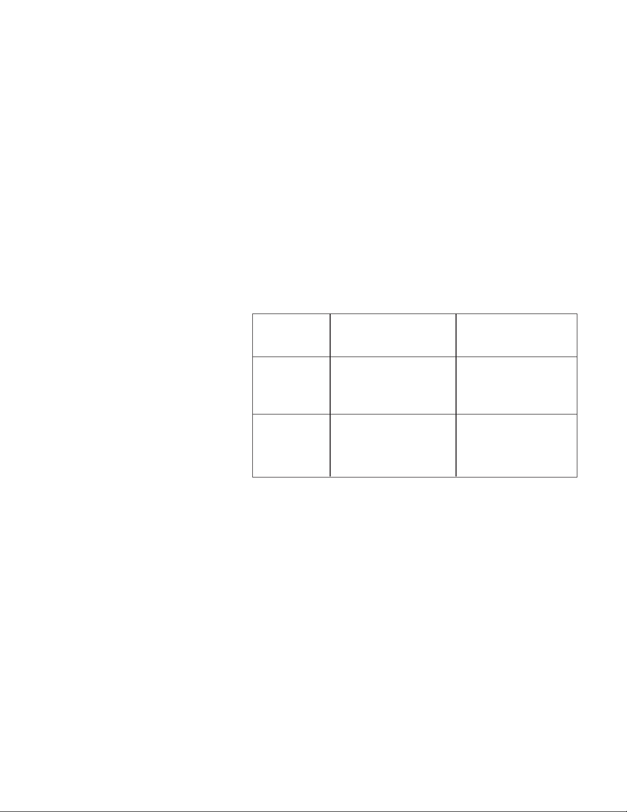
Table 1
Trim Kits Microwave Ovens
• Side Duct (1)
• Upper Exhaust Duct (1)
• Top Intake Duct (1)
• Rear Intake Duct (1)
• Installation Instructions (1)
• 10-foot Roll Tape (1)
• Screws #8 x
• Grommet (1)
• Template (1)
1/4" (20)
30" cabinet MT30BB (Black) MBBB
MT30BW (White) MBBW
MT30BS (Stainless) MBBS
27" cabinet MT27BB (Black) MBBB
MT27BW (White) MBBW
MT27BS (Stainless) MBBS
Caution:
• Trim kits are designed for use only with the Thermador microwave oven
models listed (See Table 1).
• For safety, do not alter or modify any part of this kit or oven.
Page 3
Page 4

Step 2: Cabinet Preparation
4"
14"
4"
➛
➛
A
➝
➝
➝
➝
➛
➛
➛
➛
B
C
• The cabinet cutout dimensions are shown in
Figure 1.
• It is a good practice when the microwave oven
is installed at the end of a cabinet run, adjacent to a perpendicular wall or cabinet door,
to allow at least 1/4"
of the trim and wall or door.
Trim Kits Dimensions
Width (B) MT30B 28
MT27B 25
Height (A) All Trim Kits 17" ±
Depth (C) All Trim Kits 24" ±
space between the side
-1
-1
/
/
2
" ±
2
" ±
1
1
1
1
/16"
/8"
/16"
/16"
• Your microwave oven can be installed into a
cabinet or wall by itself or above any of the
following Thermador wall ovens: C271, C301,
CM301, S301, SC301. Or, Thermador Warming Drawers WD27 and WD30 (see Figure 2).
• Outlet can be located anywhere within the
shaded area as indicated in Figure 1.
➛
Outlet should be
in the shaded area.
➛
Microwave
Cutout
Thermador
single wall
oven
cutout
Top of
microwave
shelf
}
1-3/4"
(45
mm)
Figure 1
Microwave
cutout
1-1/2"
➝
(38 mm)
}
Warming
Drawer
cutout
Figure 2
Page 4
Page 5

Step 3: Electrical Installation
The Thermador microwave oven is equipped with a grounded cord. The wall receptacle must
be installed and grounded in accordance with the national electrical code. Also, electrical
connections and grounding must comply with all applicable local codes.
The electrical requirements for a separate circuit serving only this microwave oven are: 120V,
60Hz, 20Amps
Step 4: Installing the Trim Kit
Position the two vertical trim brackets using the template as shown on Figure 3.
Mark the center line of the cutout using the template.
The template is used to locate the positions of the left and right trim brackets with
respect to the cut out. The trims are secured with three (3) screws each and the
template is discarded thereafter.
Trim Brackets
Screws #8
➝
x
1
/4"
.
➝
Template
Figure 3
Notch to mark
the center line
of the cutout
Centerline
➝
Page 5
Page 6

Step 5: Installing The Microwave Oven
Note:
ering that must be removed prior to installing them onto the microwave.
The four (4) ducts have a plastic cov-
WARNING
These ducts have sharp edges. Be careful when handling.
1. Position the oven's four (4) cone-shaped legs
on the base pan's four (4) large holes. Fasten
with five (5) screws #8 x
2. Remove and retain Outer Case Screw at left
side of the oven.
1/4"
.
3. Position Side Duct on left side of oven.
Fasten with outer case screw removed in
Step 2.
4. Position Upper Exaust Duct on top (hinge
side) of oven and fasten it together with Side
Duct by using two (2) screws #8 x1/4"
5. Remove and retain Outer Case Screw at rear
of the oven (right side).
6. Install the Grommet and the electrical cord
of the microwave in the receiving hole
provided in the Rear Intake Duct and position
this duct on rear of the oven (right side).
Fasten with Outer Case Screw.
7. Position Top Intake Duct on upper right side
of oven and fasten it together with rear intake duct by using four (4) screws #8 x1/4"
8. Secure all duct flanges to oven with tape
provided. Press tape to secure properly.
.
.
Screw
8
Microwave
Oven
Side
Duct
x 1/4"
➝
Upper
Exhaust
Duct
.
Outer
Case
Screw
Grommet
To p
Intake
Duct
Screw #8
.
.
Figure 4
x 1/4"
Rear
Intake
Duct
➝
Outer Case Screw
Base Pan
Page 6
Page 7

Step 5: Installing The Microwave Oven (continued)
9. Remove the left side vertical trim bracket
(three screws) (MT27B only).
10. Slide the assembled microwave oven part
way into the prepared cabinet cutout.
Plug the electrical cord in the wall receptacle (ask for help from another person).
Slide oven in the rest of the way into the
cabinet. Position base pan on cabinet
shelf with respect to the center line as
shown on Figure 5. The front end of pan
should align flush with the front edge of
the shelf. Fasten base pan to shelf with
two (2) screws #8 x 1/4.
11. Re-install the left side vertical trim bracket
(MT27B only).
12. Snap on the frame trim with the
Thermador logo above the microwave
door (Figure 6).
13. Install the turntable support and the
turntable inside the microwave oven.
14. Follow the Care & Use manual for operating instructions.
Figure 5
Frame Trim
Figure 6
Page 7
Page 8

Thermador reserves the right to change specifications or design without notice. Some models are
certified for use in Canada. Thermador is not responsible for products which are transported from
the United States for use in Canada. Check with your local Canadian distributor or dealer. Thermador,
5551 McFadden Avenue, Huntington Beach, CA 92649.
For the most up-to-date critical installation dimensions by fax, use your fax handset and phone
702/833-3600. Use code #8030.
BSH Home Appliances Corporation
5551 McFadden Avenue, Huntington Beach, CA 92649 • 800/735-4328
RO2003M • 5020009162A • © 2003 BSH Home Appliances Corp. • Litho Date 7/03
 Loading...