

Page 1

i ii i ii ii i i
!_i:_i_i_i_ii_i_ii_i_i:_i!ii_ii_I_III_I__i_i_i_iiiii___i__II_I:II_
VENTILATION
INSTALLATION MANUAL
MODELS: HMWB30
HMWB36
Thermedor' AoA=__°o3_°o+
LI3GJA Ed. 08/08
Page 2

APPROVED FOR RESiDENTiAL APPLIANCES
FOR RESiDENTiAL USE ONLY
READ AND SAVE THESE iNSTRUCTiONS
PLEASE READ ENTIRE iNSTRUCTiONS BEFORE PROCEEDING.
iNSTALLATiON MUST COMPLY WiTH ALL LOCAL CODES.
IMPORTANT: Save these Instructions for the Local Electrical Inspector's use.
INSTALLER: Please leave these instructions with this unit for the owner.
OWNER: Please retain these instructions for future reference.
Safety Warning: Turn off power circuit at service panel and lock out panel, before wiring this appliance.
Requirement: 120 V AC, 60 Hz. 15 or 20 A Branch Circuit
Page 3

IMPORTANT SAFETY INSTRUCTIONS
Read All Instructions Before Using the Appliance.
READ AND SAVE THESE INSTRUCTIONS
G
TO REDUCE THE RISK OF FIRE, ELECTRIC
SHOCK, OR iNJURY TO PERSONS, OBSERVE
THE FOLLOWING:
A. Use this unit only in the manner intended by the
manufacturer. Ifyou have questions, contact
the manufacturer.
B. Before servicing or cleaning the unit, switch
power off at service panel and lock service
panel disconnecting means to prevent power
from being switched on accidentally. When the
service disconnecting means cannot be locked,
securely fasten a prominent warning device,
such as a tag, to the service panel.
C. installation Work and Electrical Wiring Must Be
Done By Qualified Person(s) In Accordance
With All Applicable Codes & Standards,
including Fire-rated Construction.
D. Sufficient air is needed for proper combustion
and exhausting of gases through the flue
(chimney) of fuel burning equipment to prevent
back- drafting. Follow the heating equipment
manufacturers guideline and safety standards
such as those published by the National Fire
Protection Association (NFPA), the American
Society for Heating, Refrigeration and Air
Conditioning Engineers (ASHRAE), and the
local code authorities.
E. When cutting or drilling into wall or ceiling, do
not damage electrical wiring and other hidden
utilities.
F. Ducted systems must always be vented to the
outdoors.
CAUTION
FOR GENERAL VENTILATING USE ONLY. DO
NOT USE TO EXHAUST HAZARDOUS OR
EXPLOSIVE MATERIALS OR VAPORS.
CAUTION
To reduce risk of fire and to properly exhaust
air, be sure to duct air outside - do not vent
exhaust air into spaces within walls, ceilings,
attics, crawl spaces, or garages.
WARNING
TO REDUCE THE RISK OF FIRE, USE ONLY
METAL DUCT WORK.
Install this hood in accordance with all
requirements specified.
WARNING
To Reduce The Risk of Fire or Electric Shock,
Do Not Use This Hood With Any External Solid
State Speed Control Device.
OPERATION
a. Always leave safety grills and filters in place.
Without these components, operating blowers
could catch onto hair, fingers and loose clothing.
The manufacturer declines a II responsibility in the
event of failure to observe the instructions given
here for installation, maintenance and suitable use
ofthe product. The manufacturer further declines
all responsibility for injury due to negligence and
the warranty of the unitautomatically expires due to
improper maintenance.
This unit is manufactured for indoor use only. Do not use this unit outdoors.
Page 4

IMPORTANT SAFETY INSTRUCTIONS
Read All Instructions Before Using the Appliance.
READ AND SAVE THESE INSTRUCTIONS
Electrical requirements
IMPORTANT
Observe all governing codes and ordinances.
It is the customer's responsibility:
To contact a qualified electrical installer.
To assure thatthe electrical installation is adequate
and in conformance with National Electrical Code,
ANSI/NFPA 70 -- latest edition s-,or CSA Standards
C22.1-94, Canadian Electrical Code, Part land
C22.2 No.0-M91 - latest edition_-_-and all local
codes and ordinances.
If codes permit and a separate ground wire is used,
iris recommended that a qualified electrician
determine that the ground path is adequate.
Do notground to a gas pipe.
Check with a qualified electrician if you are not sure
range hood is properly grounded.
Do not have a fuse in the neutral or ground circuit.
IMPORTANT
Save Installation Instructions for electrical
inspector's use.
The range hood must be connected with copper
wire only.
The range hood should be connected directly to the
fused disconnect (or circuit breaker) box through
metal electrical conduit.
Wire sizes must conform to the requirements of the
National Electrical Code ANSI/NFPA 70--latest
edition s-,or CSA Standards C22.1-94, Canadian
Electrical Code Part 1 and C22.2 No. 0-M91 - latest
edition_-_-and all local codes and ordinances.
A U.L. - or C.S.A. - listedconduit connector must be
provided at each end of the power supply conduit
(at the range hood and at the junction box).
Copies of the standards listed may be obtained from:
National Fire Protection Association Batterymarch Park
Quincy, Massachusetts 02269
_CSA International 8501 East Pleasant Valley Road
Cleveland, Ohio 44131-5575
4
Page 5

Parts In cluded with your Hood
• Hood Canopy Assembly with blower already
installed
• Grease filters
• Drip tray for each filter.
• Drip trays holding brakers + plastic wahers and
knobs
• 1Transition withbackdraftdamper
• Use & Care / Installation Instructions
• Fittings bag with:
4 Washers
6 Drywall anchors
2 Hookswith regulating screws
6 ScrewsSX3S
4 Screws for transition
Op tion al accessory
Duct covers
Ductless recirculation kit available only for HMWB30,
HMWB.36 model.
Parts Not Included with your
Hood
• Duct Tape
• 1/2"Conduit
• Wire Nuts
• Round Duct.
• Wiring clamp
• A CAUTION! Lamps are not supplied, use
ONLY 120 Volt, S0 Watt (maximum) S0°
halogen light made o r a GU10 base,
suitable for usei nopen luminarie .
• 4 #10 pan head wood screws for installation on
a bottomofa cabinet
3 prong plug
Tools required
Flat blade and Phillips screwdrivers
Pencil and tape measure
Metal snips (in some applications)
Electric drill
Saw (saber or keyhole)
Pliers
Level
Caulking
Flashlight
Wire stripper
Safety glasses
Gloves
Step ladder
INSTALLING THE HOOD
• For the most efficient air flow exhaust, use a
straight run or as few elbows as possible.
il_ CAUTION: Vent unittooutsideof
building, only.
• Two peopleare necessary for installation.
On average 2 hours are necessary to complete
installation (without considering cut to be done
on wall and or on cabinet, installation of ducts,
conduit and electrical connections to the mains).
installation steps:
11 installation steps are required for both
installation methods
Wall mount installation steps or in a Iternative
Cabinet installation
• The hood is fittedwith Screws and Drywall
Anchors suitable for most surfaces, consult a
Qualified Installer, check if they perfectly fit with
your cabinet/wall.
• Do not use flex ducting.
• COLD WEATHER installations should have an
additional backdraft damper installed to
minimize backward cold air flow and a
nonmetallic thermal break to minimize
conduction of outside temperatures as part of
the ductwork. The damper should be on the
cold air side of the thermal break.
The break should be as close as possible to
where the ducting enters the heated portion of
the house.
• Make up air: Local building codes may require
the use of Make-Up Air Systems when using
Ducted Ventilation Systems greater than
specified CFM of air movement.
The specified CFM varies from location to location
Consult your HVAC professional for specific
requirements in your area.
Page 6

Typical installation
The height from the countertop to the bottom of the hood is 30" to 36".
These hoods are not recommended to be used over indoor grills.
1. Choose vent options
The hood is designed to be used for vertical discharge as shown below.
Note: see also Fig. 1-2-3 for Cabinet preparation.
Install a 1/2" conduit from the service panel long enough to reach the hood
once it is installed. Power supply must be rated for 120 VAC, 60Hz. 15 or 20A.
Examples of possible ducting
Ceiling
*Deflector
Lamp
\
Hood
1
30" to 36"
Transition
Blower
*Charcoal filters
Filter
Round duct
Ceiling
Lam p
Hood
30" to 36"
1
Transition
Blower
Filter
* Charcoal filters
Optional accessory - Ductless recirculation kit
Page 7

DUCT FITTINGS
Use this chart to compute maximum
permissable lengths for duct runs to
outdoors.
Note: Do not exceed maximum permissable
equivalent lengths!
Maximum recommended duct
length for these hoods: 150 feet
Flexible ducting:
If flexible metal ducting is used, all
the equivalent feet values in the table
should be doubled. The flexible
metal duct should be straight and
smooth and extended as much as
possible.
Do NOT use flexible plastic ducting.
Note: Any home ventilation system, such as a
ventilation hood, may interrupt the proper flow of
combustion air and exhaust required by fireplaces,
gas furnaces, gas water heaters and other naturally
vented systems. To minimize the chance of interruption
of such naturally vented systems, follow the heating
equipment manufacturer's guidelines and safety
standards such as those published by NFPA and ASHRAE.
*Hoods are supplied with a 10"
round transition. A locally
supplied transition is required
for other sizes.
Note: Outlet on top of hood is
8-1/8" x 8".
Q
©
10" round
to 8" roun d
Round,
straight
3-1/4" x 10"
3-1/4" x 12 "
straight
90° elbow
45° elbow
3-1/4" x 12" 15 ft.
3-1/4" x 10" 14 ft.
90° elbow
3-1/4" xlO" 8ft.
3-1/4" x12" 9ft.
45° elbow
3-1/4" x 10" 33 ft.
3-1/4" x 12" 36ft.
go° fiat elbow
10" round transition
to 3-1/4" x 10" or
3-1/4" x 12" 9ft.
3-1/4" x 10" or
3-1/4" x 12" to
10" round transition 6 ft.
10" round to 3-1/4" x 10" 16 ft.
3-1/4" x 12" transition 13 ft.
go° elbow
3-1/4" xlO" 9ft.
3-1/4"x12"t o10" round 8ft.
transiti on 90° elbow
Round
wall cap
with damper
3-1/4" x 10" 24 ft.
3-1/4" x 12" wall cap 26ft.
with damper
Sft.
1ft.
(per foot
length)
1ft.
(per foot
length)
8" Dia. 17 ft.
10" Dia. 24 ft .
8" Dia. 10 ft.
10" Dia. 14ft .
8" Dia. 32 ft.
10" Dia.41 ft.
Round
roof cap
8" Dia. 44 ft.
10" Di a. 56 ft.
TotalDuct Run
Page 8

For safety reasons, ducting should vent directly outdoors (not into an attic, underneath the house, into the
garage or into any enclosed space).
Keep duct runs as short and straight as possible.
Duct fittings (elbows and transitions) reduce air flow efficiency.
Back to back elbows and "S" turns give very poor delivery and are not recommended.
A short straight length of duct at the inlet of the remote blower gives the best delivery.
Transition to duct from the integral blower to remote duct transition as close as possible.
In order opreference, use:
1st. 10" round duct
2nd. 8round duct
3rd. 3-1/4" x 14" duct
4th. 7" round duct
5th. 3-1/4" x 10"duct
6th. 6" round duct
The use of flexible metal round duct should only be used when no other duct fitting exists. Limit use to short
lengths and do not crush when making corners.
1. Prepare duct and conduit cut outs, see figures
1 and 2 as needed.
i
Mo0o3o,,36,,
it,8, 1-1,2"o,a..o,os
Bottom of
Cabinet or
Soffit
12"
Rear
Wall
11
10-112" " '
%÷ I I /_ C_<-_-1_7f/ Vertical conduit
CL
_Hood Width
Figure 1
2. Assembly of the 10" transition:
The transition supplied with the hood mounts to
the top.
Do not install transition until hood is
fixed on cabinet or wall.
a. Place the transition piece over the hood
outlet and secure with 4 screws provided.
(Figure3)
b. Wrap all joints (metal transition and hood)
with duct tape for an airtight seal.
c. Remove tape holding damper.
Hood outlet
Figure 2
Figure 3
Transition
23-1/8"
Screws (4)
Page 9

Wall Mount Installation
Note: see below if cabinet installation ispreferred
3. After the hood installation height has been
determined draw a horizontal line at a distance
above the cooktop equal to the desired hood
installation height plus 7- 1/2". See also Figure 4a.
4. Find the centerline of the cooktop. Draw a
vertical line along this centerline up to the hori-
zontal line drawn in step 1 and draw a vertical
line right and left at a distance of12-5/8" to
determine the mounting Iocationofthe
mounting hooks shipped with the hood.
5. Fit two mounting hooks on the wall to hang the
hood through the provided slots (2 wall
anchors + 2 hooks + 2 screws 5x35).
6. Run 10" Duct, long enough to reach the
transition once the hood has been installed plus
1 1/2" inch to connect ductwork. Fix Duct to
transition with screws and seal withtape.
7. Remove 1of 2 knockouts and install 1/2"
conduit connector in j-box.
8. Hang the hood and adjust its position through
the screws on the hooks.
9. Fix the hood to 4 additional point, 2 on
upperside, 2 on lower side (use 4 wall anchors
+ 4washers + 4 screws 5x35.
HOOD WIDTH DIM. "W" DIM. "K" DIM. "Z"
30" 29 - 1/8" 2 - 1/2" 7 - 1/16"
36" 35 - 1/16" 2 - 1/2" 7 - 1/16"
Table 3
Figure 4a
Knockouts
(junction
box)
7 1/2' l
W
Side slot x 4
bottom fixing
screws locations
Square
slot
CenterHole
Z
Top
location
Cabinet Installation:
Note: Seeabove ifwall mount installation is preferred
Note: Distances on Table 3.3.
Find the centerline of the cabinet bottom. Draw a line
along this centerline from rear to front of the cabinet.
See also Figure 4b.
4. Draw two lines, one at a K distance from thewall,
the other one at a Z distance from theprevious line.
Mark 4 points, two along each line at a distance of
halfW from the center line, to determine the screw
locations.
5. Fit 4 screws on cabinet bottom do not tighten
completely but leave a space of about 1/2" from
cabinet bottom surface and head screws.
6. Run 10" Duct, long enough to reach the transition
once the hood has been installed plus1 1/2" inch for
connect ductwork.
7. Remove 1of 2 knockouts and install 1/2"conduit
connector in j-box.
8. Hang the hood on screws through side slots provided
on hood top.Tighten the four screws. Note: If possible
fix the hood on the wall at 4 additional point (2 on
upper side, 2 on Iowerside).
9. From the inside of the cabinet attach the transition
on upper outlet.
© ©
Hook for wall Screw for
/installation cabinet
_ 25:3/16" _ _'_ bottom
/_ _===_==_ ': =_ I_,_ installation
,, 12 5/8" 1 12 5/8" _" _Adjusting
7 112" I _f'_L _'_ screw
Bottom of the Hood
Figure 4b
_K
\
Page 10

Fix Duct to transition and seal with tape.
For both installation method"
l O.Wiring the HOOD:
WARNIN G:
ToAvoid Electrical Shock Hazard
Turn off power at the service
panel before wiring this unit.
120 VAC, 15 or 20 Amp circuit
required .
ELECTRICAL GROUNDING INSTRUCTIONS
THIS APPLIANCE IS FITTED WITH AN
ELECTRICAL JUNCTION BOX WITH 3
WIRES, ONE OF WHICH (GREEN/YELLOW)
SERVES TO GROUND THE APPLIANCE.
_ WARNIN G:
TO PROTECT YOU AGAINST ELECTRIC SHOCK,
THE GREEN AND YELLOW WIRE MUST BE
CONNECTED TO THE GROUNDING WIRE IN
YOURHOME ELECTRICALSYSTEM, AND IT MUST
UNDER NO CIRCUNSTANCES BE CUT OR REMOVED.
Failure to do so can result in death or
electrical shock.
Power supply conduit
• Remove the j-box cover as shown in
Figure S.
• If not already done, install 1/2"conduit
connector in j-box.
• Run black, white, and green wires (#14
AWG) according to the National Electrical
Code or CSA Standards and local codes and
ordinances.
• Connect black, white, and green wires from
power supply to black, white, and green/
yellow wires in j-box respectively.
• Close j-box cover.
Final installadon steps
1.Install grease filters, lamps and drip trays as
described in the Care & Use section of this
manual.
Note: Lamps are not supplied, use ONLY 120
Volt, SOWatt (maximum) 50° halogen light
made for a GUIO base, suitable for use in
open luminarie .
Turn power on at service panel.
From
control
panel
Figure 5
10
Page 11

IMPORTANTES INSTRUCTIONS DE SI CURITI
VEUILLEZ LIRE ENTIEREiVENT CES INSTRUCTIONS AVANT DE PROCEDER DE
EUTILISATION DE VOTRE APPAREIL.
VEUILLEZ LIRE ET CONSERVEZ SOIGNEUSEMENT CES INSTRUCTIONS
ATTENTiO
POUR REDUIRE LE RISQUE D'INCENDIE, DE
CHOC ELECTRIQUE OU DE BLESSURES,
VEUILLEZ OBSERVER LES INDICATIONS
SUIVANTES :
AiN'ulJliser I'appareil que conformement aux
inslzuclJons du conslzucl_ur: ne pas se
conformer aux inslzuclJons peut s'averer dangeu-
reux etannuler la garanlJe. Si vous avez des
queslJons, n'hesitez pas a prendre contact avec le
fabricanL
BiAvantl_ute int_rvenlJon sur volze appareil,
met_z le boulDn d'allumage en posilJon OFF
Veillez al_ujours debrancher le cable
d'alimentalJon eleclzique avantde proceder
l_ut_ reparalJon ou nettuyage de volze appareil.
Lorsqu'il n'est pas possible de debrancher le
cable d'alimentalJon eleclzique, veillez a installer
sur le tableau de commande (par exemple), une
signalelJque d'averlJssement bien visible, t_lle
qu'une elJquete de couleur rouge oujaune
cont_nantdes indicalJons de securite.
C.Les Travaux d'installalJon de I'appareil, installa-
lion eleclzique inclue, doiventelze nbalises par du
personnel qualifie, ceci de conformite avec les
normes etdiverses reglementalJons en vigueur.
D.Afin d'evit_r l_ut rel_ur de fumees ou aulzes
vapeurs de cuisson, il est necessaire qu'il exist_
un flux d'air suffisant passantau lyavers de la
hottE Observez les inslzuclJons du fabricantde
volze appareil de cuisine (gaz ou eleclzique) tels
que ceux publies par la NalJonal Fire RoteclJon
AssocialJon (NFPA), me American Society for
Healing, RefrigeralJon and Air condilJoning
Engineers (ASHRAE), ainsi que la reglementa-
lion locale de volze lieu de residence (lieu ou est
ulJlise I'appareil).
EiLorsque vous perforez ou effec_Jez une rainure
dans un mur, veillez ane pas endommager
I'installalJon eleclzique, ainsi que 1put aulze
installalJon qui s'y lzouve occulte.
ELesconduits de venlJlalJons doiventtuujours
aboulJr aI'exterieur de volze residence.
ATTENTION
PRUDENCE
APPAREIL DESTINe: UNIQUEMENT .&.DES
FINS DE VENTILATION GENC:RALE EN
USAGE DOMESTIQUE. AFIN D'EVITER TOUT
RISQUE D'EXPLOSION, NE PAS UTILISER
POUR VENTILER OU EXTRAIRE DES
VAPEURS OU FUMEES PROVENANT DE
SUBSTANCES DANGEREUSES OU EXPLO-
SIVES.
PRUDENCE
Afin de reduire l_ut risque d'incendie etd'exlzaire
correcl_mentles fumees etvapeurs, veillez
brancher les conduits de la hot_ vers I'exterieur
de volze residence. Ne pas evacuer les fumees
etvapeurs de cuisine vers les colonnes seches,
les espaces existantenlze deux murs, les
espaces sous plancher ou des greniers.
ATTENTION
POUR REDUIRE LE RISQUE D'INCENDIE,
LORS DE ILINSTALLATION DE CONDUITS DE
RACCORDEIVENT ET D'EXTRACTION,
N'UTILISER QUE DES CONDUITS IVETAL-
LIQUES.
Installer la hot_ en suivantlDut_s les indicalJons
et speciflcalJons necessa ires et reglementaires.
ATTENTION
Afin d'eviter 1put risque d'incendie ou de choc
eleclzique, ne pas ulJliser cetappareil avec un
disposilJfde programalJon ou de conlzOle de la
vit_sse de fonclJonnemenL
OPERATION
aiNejamais relJrer les grilles d'ecoulementou
les fillzes agraisses.
Sans ces disposilJfs, les venlJlateurs peuvent
at_per au vol cerlaines parlJes de volze corps
(cheuveux, doigts) ou de vos vetements.
Le fabricantdecline tuute responsabilite dans le
cas ou les inslzuclJons d'installalJon, enlzelJen et
ulJlisalJon, fournies avec I'appareil ne seraient
pas observees.
Le fabricantdecline egalementtuut_ respon-
sabilite relalJve aux blessures produites ala suit_
de negligences de la partde I'ulJlisateur et
signale que la garanlJe de I'appareil ne sera plus
valable dans le cas ou I'appareil n'est pas
correct_mentenlzet_nu et/ou repare.
11
Page 12
IMPORTANTES INSTRUCTIONS DE SECURITI:!:
VEUILLEZ LIRE ENTIEREIVENT CES INSTRUCTIONS AVANT DE PROCEDER
A EUTILISATION DE VOTRE APPAREIL.
VEUILLEZ LIRE ET CONSERVEZ SOIGNEUSEMENT CES INSTRUCTIONS
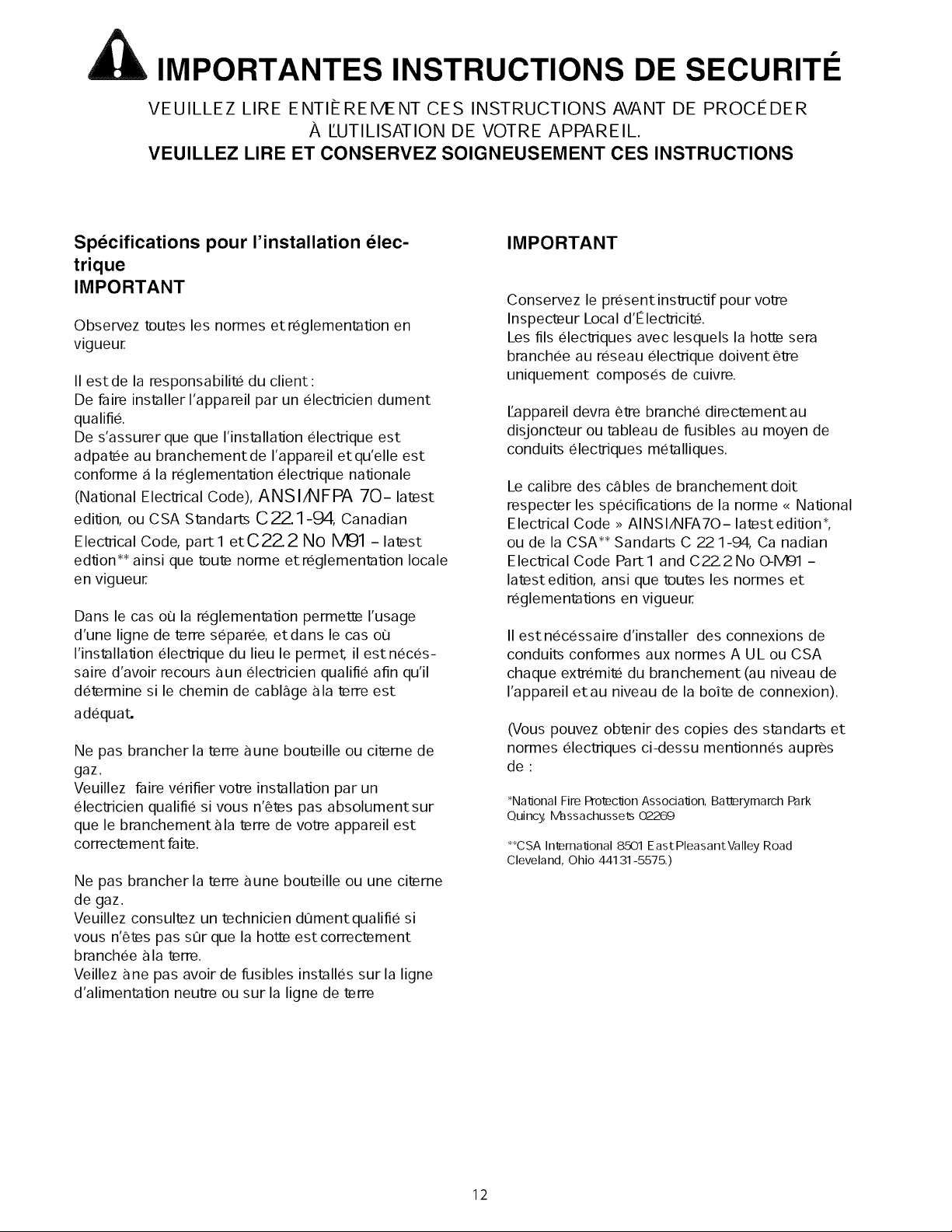
Specifications pour I'installation elec-
trique
IMPORTANT
Observez teutes les normes et reglementalJon en
vigueur.
II estde la responsabilite du client:
De faire installer I'appareil par un elecl]icien dument
qualifie.
De s'assurer que que I'installalJon eleclzique est
adpatee au branchementde I'appareil etqu'elle est
conforme a la reglementalJon eleclzique nalJonale
(NalJonal Eleclzical Code), ANSIAIFPA 70-latest
edilJon, ou CSA Standarts C22.1-94, Canadian
Eleclzical Code, part1 etC22.2 No M91 -latest
edlJon** ainsi que teute norme et reglementalJon locale
en vigueur.
Dans le cas oo la reglementalJon permet_ I'usage
d'une ligne de terre separee, etdans le cas oo
I'installalJon elecl]ique du lieu le permet_ il estneces-
saire d'avoir recoups gun eleclzicien qualifie afin qu'il
determine si le chemin de cablSge ala terre est
adequat_
Ne pas brancher la terre aune bouteille ou citeme de
gaz.
Veuillez faire verifier volze installalJon par un
eleclzicien qualifie si vous n'¢tes pas absolumentsur
que le branchementala terre de volze appareil est
correctement fa ite.
Ne pas brancher la terre aune bouteille ou une citeme
de gaz.
Veuillez consultez un technicien dQmentqualifie si
vous n'¢tes pas sur que la hot_ est correctement
branchee ala terre.
Veillez ane pas avoir de fusibles installes sur la ligne
d'alimentalJon neulze ou sur la ligne de terre
IMPORTANT
Conservez le present inslzuclJf pour volze
Inspecteur Local d'Eleclzicite.
Les ills eleclziques avec lesquels la hotl_ sera
branchee au reseau elecl]ique doivent ¢lze
uniquement composes de cuivre.
ILappareil devra ¢lze branche directementau
disjoncteur ou tableau de fusibles au moyen de
conduits eleclziques metalliques.
Le calibre des cSbles de branchementdoit
respecter les speciflcalJons de la norme <<NalJonal
Eleclzical Code >_AINSIAXIFA70- latestedilJon*,
ou de la CSA** Sandarts C 22 1-94, Ca nadian
Eleclzical Code Part1 and C22_2 No OqVl91-
latest edilJon, ansi que teutes les normes et
reglementalJons en vigueur,
II estnecessaire d'installer des connexions de
conduits conformes aux normes A UL ou CSA
chaque exlmbmite du branchement (au niveau de
I'appareil etau niveau de la boite de connexion).
(Vous pouvez obtenir des copies des standarts et
normes eleclziques ci-dessu menlJonnes aupres
de:
*NalJonal Fire Pro_clJon AssocialJon, Baterymarch Park
Quincy, IVhssachussets 02269
**CSA InernalJonal 8501 EastPleasantValley Road
Cleveland, Ohio 44131-5575.)
12
Page 13

Pi ces fournies avec votre hotte.
• Cloche de hotte avec ventilateurs pr_-install_s.
• Filtres _ graisses.
• Grille d'_coulement.
• Molettes de fixation des grilles d'ecoulement et boutons en
ptastique.
• Une connexion de ventilation ronde.
• Manuels d'installation et d'entretien.
• Un Sachet d'accessoires contenant:
• 4 rondelles.
• 6 chevilles.
• 2 crochets avec visse r_glables.
•6 visses 5x35.
•4 visses 2,9,6,5, pour connexion
Accessoires optionnels
Couvre-conduits
Un kit de recyclage d'air sans conduit est
disponible pour le module HMWB30 HMWB36
Pi ces non fournies avec votre hotte •
•Joint de conduit.
•Conduit de I/2".
•Ecrous de connexion _lectrique.
•Agrafes / fixations de c_blage _lectrique
_IL ATTENTION: Les lampes ne sont pas fournies,
UTILISER UNIQUEMENT des lampes hallog_nes de 120
VOLTS d'une puissance de 50 Watts (maximum)
50 degr_s ou _ base GU10, adapt_e _ I'utilisation en
luminaire ouvert.
•4 visses .10 _ bois _ t_te frais_e pour installation sur le
fond d'un meuble.
Outils n_c_ssaires :
•Tournevis plat et tounevis de type Philips.
•Crayon et d_cim_tre (un m_tre).
•Pinces coupantes pour m_tal (pour certaines t_ches)
•Une perceuse _lectrique
•Une Scie (scie sauteuse ou de type trou de serrure).
•Des pinces
•Un niveau
•Un burin
•Du ruban isolant
•Une lampe _lectrique
•Une pince _ d_nuder les c_bles
•Des lunettes de s_curit_
•Des gants
•Une _chelle
INSTALLATION DE LA HOTTE
•Pour obtenir un maximum d'_fficacit_ en extraction
de fum_es et vapeurs de cuisson, utiliser un conduit
le plus droit possible, avec le minimum de coudes et
autre type de connexions possibles.
PRUDENCE : ventiler uniquement vers
l'ext_rieur du b_timent.
•II faut une personne pour r_aliser l'installation.
•II faut en moyenne 2 heures pour r_aliser
l'installation (sans compter les ajustements qu'il
peut falloir r_aliser au niveau du mur ou du meuble,
ni l'installation des conduits d'_vacuation ou celle
des conduits _lectriques qui permettront le raccor-
dement au r_seau _lectrique principal).
Etapes de l'installation :
•II faut compter 11 _tapes d'installation quelque soit
la m_thode envisag_e: sur mur ou sur meuble.
•L'appareil est accompagn_ de visses et de chevilles
adapt_es _ la plupart des surfaces possibles
d'installation, n_namoins, veuillez consulter un
technicien ou insstallateur qualifi_ afin de v_rifier
leur ad_quation _ votre surface d'installatio
•Ne pas utiliser de conduit d'_vacuation flexibles.
•BASSESTEMPERATURES: IIest recommand_
d'installer un r_ducteur de connexion suppl_-
mentaire, afin de r_duire les _ventuels retours
d'air ainsi qu'un amortisseur thermique non
metallique (joint non metallique au niveau des
r_ducteurs et connexions) afin de minimiser
l'_change de temperature int_rieure/ext_rieure.
Le r_ducteur devra _tre install_ du c6t_ <<
ext_rieur _>de l'amortisseur thermique, lequel
doit se trouver le plus proche possible du point
oO le conduit d'_vacuation entre dans la zone
chauff_e de la maison.
• Syst_mes de ventilation : La r_glementation en
vigueur dans votre lieu de r_sidence peut exiger
l'utilisation de syst_me de ventilation r_sidentiel
additionnel lorsque vous utilisez des appareils de
ventilation/extraction d'air qui requi_rent
l'installation de conduits d'_vacuation et dont la
puissance est sup_rieure aux specifications CFM
de courants d'air. Lesnormes et specifications
CFM varient selon le lieu de r_sidence : consultez
votre professionnel HVAC pour connaitre les
normes et specifications applicables _ votre lieu
de r_sidence.
13
Page 14
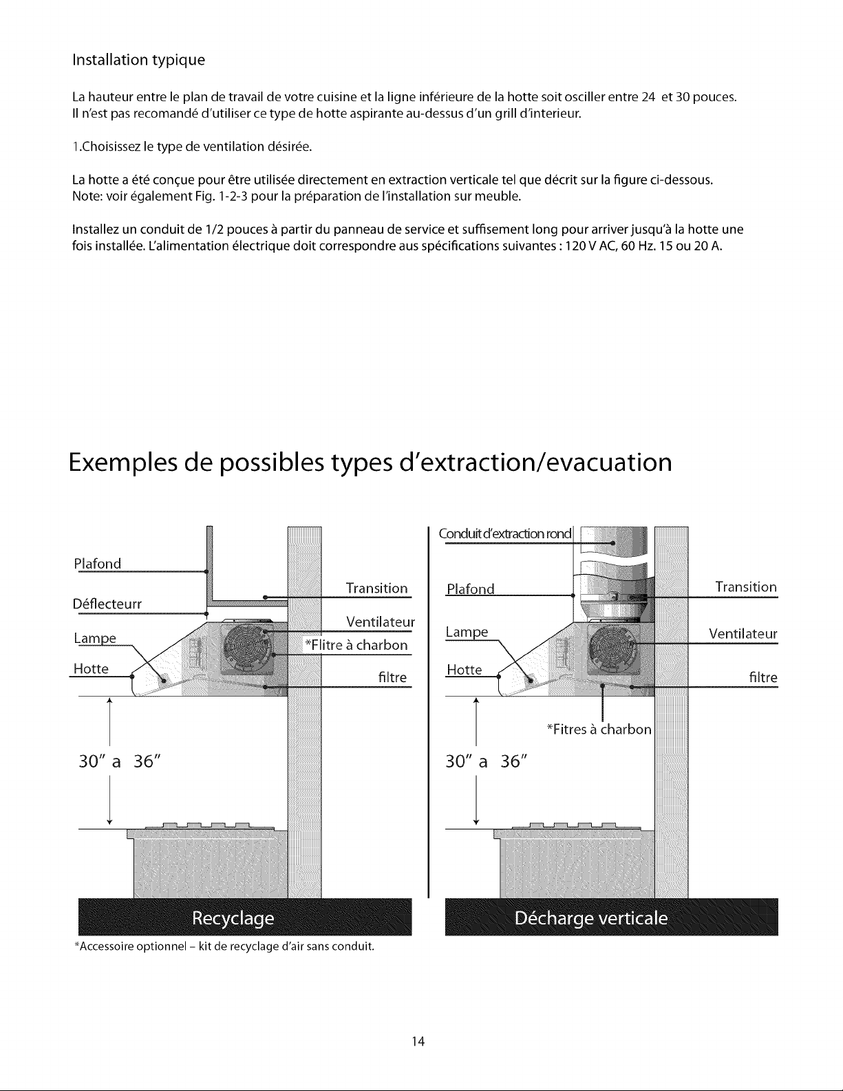
Installation typique
La hauteur entre le plan de travail de votre cuisine et la ligne inf@ieure de la hotte soit osciller entre 24 et 30 pouces.
II n'est pas recomand_ d'utiliser ce type de hotte aspirante au-dessus d'un grill d'interieur.
l.Choisissez le type de ventilation d_sir_e.
La hotte a _t_ tongue pour _tre utilis_e directement en extraction verticale tel que d_crit sur la figure ci-dessous.
Note: voir _galement Fig. 1-2-3 pour la preparation de I'installation sur meuble.
lnstallez un conduit de 1/2 pouces _ partir du panneau de service et suffisement long pour arriver jusqu'_ la hotte une
fois install_e. L'alimentation _lectrique doit correspondre aus specifications suivantes : 120 V AC,60 Hz. 15 ou 20 A.
Exemples de possibles types d'extraction/evacuation
Conduitd'extractionrond
Plafond
Plafond Transition
D_flecteurr
Lain
Hotte
30" a 36"
_-- _ Transition
Ventilateur
i
*Flitre _ charbon
filtre
_e Ventilateur
Hotte filtre
T
30"a
_Fitres _ charbon
1
_Accessoire optionnel - kit de recyclage d'air sans conduit.
14
Page 15
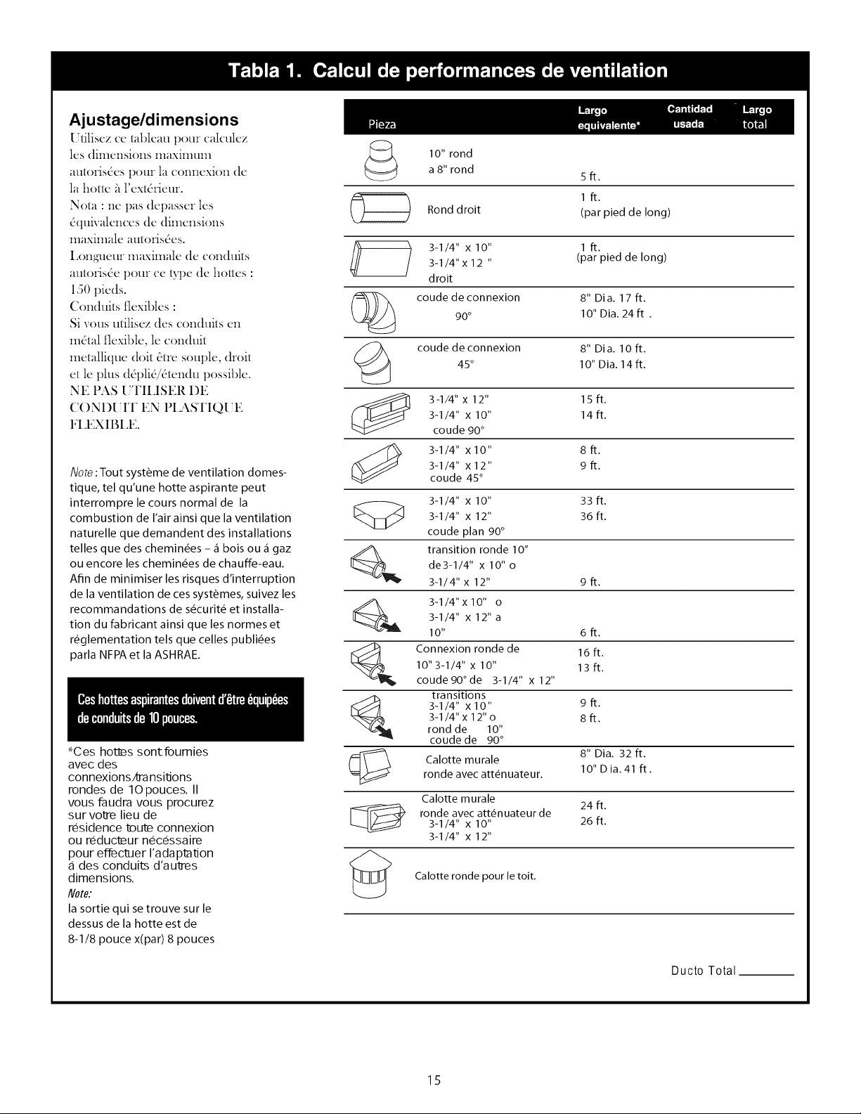
Ajustage/dimensions
[ tiliscz (c tableau potlr (alculcz
los dimei_sions lllaXitlltllll
autoIisdes pore la connexion (lc
la houc h l'cxtdiicui.
Nota : nc pas (lcpasscr los
dquix alen(es dc (limcnsions
maximalc autoiisdes.
Loilgtletlr maximalc (lc con(hlits
autorisdc pOtlI cc type (lc hottcs :
150 picds.
Coll(luits t]cxiblcs :
Si _ous utilisez des conduits cn
mdtal flexible, lc conduit
metallique doit dtre souple, droit
et le phls (ldplid/dtendu possible.
NE PAS [ TILISER I)E
CONI)[ IT EN PIASTIQ[ E
FLEXIBLE.
Note :Tout syst&me de ventilation domes-
tique, tel qu'une hotte aspirante peut
interrompre le cours normal de la
combustion de I'air ainsi que la ventilation
naturelle que demandent des installations
telles que des chemin6es - _ bois ou _ gaz
ou encore les chemin6es de chauffe-eau.
Afin de minimiser les risques d'interruption
de la ventilation de ces syst&mes, suivez les
recommandations de s6curit6 et installa-
tion du fabricant ainsi que les normes et
r6glementation tels que celles publi6es
parla NFPA et laASHRAE.
*Ces hotl_s sontfoumies
avec des
connexions/ma nsitions
rondes de 1Opouces. II
vous faudra vous procurez
sur volre lieu de
residence tmutmconnexion
ou reductmur necessaire
pour effeclner I'adaptalJon
des conduits d'au'mes
dimensions,
Note:
la sortie qui setrouve sur le
dessusde la hotte est de
8-1/8 pouce x(par) 8 pouces
10" rond
a 8" rond 5 ft.
Rond droit (par pied de long)
3-1/4" x 12 " (par pied de long)
3-1/4" x 10" 1 ft.
droit
90° 1O"Dia. 24 ft .
coude de connexion 8" Dia. 17 ft.
(_ coude de connexion 8" Dia. lOft.
[_1_ transition ronde 10"
[_IL 3-1/4" x 10" o
_ Connexion ronde de 16 ft.
[_ transitions
(_ Calotte murale 8" Dia. 32 ft.
45° 10" Dia, 14ft,
3-1/4" x 10" 14ft.
3-1/4" x 12" 15ft.
coude 90 °
3-1/4" x12" 9ft.
3-1/4" xlO" 8ft.
coude 45°
3-1/4" x 10" 33 ft.
3-1/4" x 12" 36ft.
coude plan 90°
de3-1/4" x 10" o
3-1/4" x 12" 9 ft.
3-1/4" x 12" a
I0" 6ft.
10"3-1/4" x 10" 13ft.
coucle 90 ° de 3-1/4" x 12"
3-1/4" xl0" 9ft.
3-1/4" x 12" o 8ft.
rond de 10"
coude de 90 °
roncle avec att#nuateur. 10" D ia. 41 ft.
Calotte murale
ronde avec att6nuateur de
3-1/4" x 10" 26ft.
3-1/4" x 12"
Calotte ronde pour le toit.
1ft.
24 ft.
15
Ducto Total
Page 16

Pourdesraisonsdes6curit6,I'exactrationdesfum6esetvapeursdecuissondoitsefairedirectementversI'ext6rieurdu
b_timentNepas6vacuer les fum6es et vapeurs de cuisine vers les colonnes s_ches, les espaces existant entre deux murs,
les espaces sous plancher ou des greniers.
Faites en sorte que les conduits soit aussi court et droits que possible.
Les connexions et r6ducteurs de taille de conduit, r6duise le volume d'air qui est evacu6.
Les coudes de connexions en zizag ainsi que les connexions en Srendent I'extraction de fum6es et vapeurs de cuisson peu
6fficace et ne sont pas recommand6es pour ce type de hotte aspirante.
Parodre de pr6f6rence d6croissante utilisez:
Un bout de conduit, court et droit juste au niveau de I'entr6e d'air du ventilateur, permet d'obtenir les meilleurs r6sultats.
II est recommand6 que le passage du conduit au ventilateur se fasse le plus pr6s possible de I'entr6e de la hotte.
1.conduit fond de 10 pouces
2.conduit fond de 8 pouces
3.conduit de 3-1/4 x 14 pouces
4.conduit ronde de 7 pouces
5.conduit de 3-1/4 x 10 pouces
6.conduit rond de 6 pouces
N'utilisez de conduit m6tallique flexible que dans le cas oO il n'y aurait aucun autre type de conduit m6tallique
disponible. Limitez son utilisaton _ de courtes distances et veillez _ ne pas 1'6craser Iorque vous formerez un
coude ou un coin.
1. D6coupez les conduits aux mesures appropir6es pour votre
installation..
I [ Model 30" 36"
Devant du cabinet X 2-3/4" 4 9/16"
Dessous du cabinet
J _ " ' Decharge verticale
P
\ --i
12"
2.Montez/assemblez lesconnexion/transition de 10 pouces: la
connexion qui est fournie avec la hotte doit _tre install6 sur le
dessus.
Ne pas installez cette connexion avant d'avoir fix6 la hotte sur
lemur ou le meuble auquel elle est destin6e.
a.Montez la connexion/transition sur la sortie d'air de la hotte
et fix6e-la au moyen des 4 visses qui sont fournies. (Figure 3).
b.Envellopez tous lesjoints (tansition m6tallique et hotte) avec
du ruban isolant de telle fa(_onqu'il n'y ait pas de fuite d'air _ ce
niveau.
c.Retirer le ruban qui tient I'att6nuateur.
1
, 4,
¢k
largeurdelaho_e
Sortie de la hotte.
Figure 1
Figure 2
11"
Figure 3
j
l
Transition.
Visses (4)
16
Page 17

INSTALLATIONSURMUR
Veuillez consulter ci-dessous, le type d'installation que vous
pr6f6rez.
3.Apr_s avoir d6termin6 _ quelle hauteur vous installerez la hotte,
tracez une ligne horizontal au-dessus des plaques de cuissons,
une distance qui soit 6gale _ la hauteur d'installation de la hotte
plus 7-1/2 pouces. Voir 6galement la figure 4a.
4.1dentifiez le centre des plaque de cuissons et tirez une ligne
verticale depuis les plaques jusqu'_ la ligne horizontale que vous
venez de tracer. Puis tracez une ligne verticale _ droite et _ gauche
de la ligne centrale, jusqu'_ une distance de 12-5/8 pouces, de
telle fa(_on que vous puissiez d_terminer I'emplacement des
crochets qui sont fournis avec I'appareil.
5.Mettez deux crochets de montage sur lemur pour accrocher la
hotte au moyen des emplacements pr_vus &cet effet sur
I'appareil (2 chevilles, 2 crochets de montage et deux visses 5x35).
6.1nstallez le conduit de 10 pouces, de telle sorte qu'il soit
suffisement long pour se brancher sur la connexion une lois la
hotte install6e. Rajoutez 1 1/2pouces de plus _ la Iongueur du
conduit afin de permettre le raccordement. Assurez le branche-
ment _ I'aide des visses et scellez-le avec de ruban isolant.
7.Retirez un des deux tampons tel qu'indiqu6 sur la figure 4a et
installez le connecteur du conduit de1/2 pouces _ la boite de
jonction.
8. Placez la hotte sur les crochets qui sont dans lemur et ajustez
sa position grace aux visses de r6glage des crochets.
9.Accrochez la hotte _ I'aide des 4 autres emplacements pr6vus
cet effet :2 sur le dessus et 2 sur la partie inf_rieure (utilisez 4
chevilles, 4 rondelles et 4 visses 5x35).
largeurdel'appareiL DIM. "W" DIM. "K" DIM. "Z"
30" 29-I/8" 2- I/2" 7-I/16"
36" 35-I/16" 2- I/2" 7-I/16"
Table 3
emplacements lat6raux
Figure 4a
Tampons
7 1/2' t
W
emplacement
des visses
sup6rieures.
emplacement carr6
emplacement de fixation de
visses inf_rieures.
INSTALLATION SUR MEUBLE:
Nota: euillez consultez les distance sur la table 3.3
Trouvez la ligne centrale du fond du meuble et tirez un trait tout
au long de cette ligne, depuis I'arri_re jusqu'_ I'avant du cabinet.
Voir aussi la figure 4b.
4.Tracez deux lignes, I'une _ une distance Kdu mur, et I'autre
une distance Z de la ligne que vous venez de tracer. Marquez 4
points, deux sur chaque ligne _ une distance de la moiti6 de W
partir de la ligne central, afin de d6terminer I'emplacement des
visses.
5.1nstallez 4 visses sur le fond du cabinet sans les serrez, en
laissant un espace d'_ peu pros 1/2pouce entre lefond du meuble
et la t_te des visses.
6.1nstallez le conduit de 10 pouces, de telle sorte qu'il soit
suffisement long pour se brancher sur la connexion une lois la
hotte install6e. Rajoutez 1 1/2pouces de plus _ la Iongueur du
conduit afin de permettre le raccordement.
7.Retirez un des deux tampons tel qu'indiqu_ sur la figure 4a et
installez le connecteur du conduit de1/2 pouces _ la boite de
jonction.
8.Accrochez I'appareil _ I'aide des emplacements lat6raux pr6vus
cet effet sur le dessus de la hotte: Serrez les 4 visses. Nota : si
possible fixez la hotte sur lemur avec 4 point suppl6mentaires :
2 sur le dessus et 2 sur la partie inf_rieure.
9.Depuis I'int6rieur du meuble, raccordez la connexion/transition
sur la sortie sup6rieure.
© ©
crochet
d'installation
/ murale.
%_ 25:3116" ,_ 171_
-- CL
Figure 4b
fond de I'appareil.
K
Visses pour l'installation
sur meuble.
17
Page 18
1QFixez le conduitau connecteur et scellez-le avec du
ruban isolan
_tL ATTENTION Risque d'accidentelectrique.
Precaution : Met_z I'interrupteur de marche sur OFF
avantde brancher cetappareil au reseau d'alimenlation. II
estnecessaire de disposer d'un circuitd'alimentation de
12OV AC, 15ou 2OAmp.
INSTRUCTIONS DE MISE .&.LA TERRE
Cetappareil estequipee d'une boite de
jonction/connexion electrique atrois ills, dont I'un (le
jaune-vert) s'utilise pour la raise ala terre de I'appareil afin
de vous protegez d'eventuels chocs electriques. Le c_ible
jaune-vert doitetre branche ala ligne de terre de
I'installation electrique de votre maison etne doitsous
aucun pretexte etre coupe ou elimine.
Le fait de ne pas observer ces recomandations peut
avoir pour consequences des chocs electriques ou
m6me la mort.
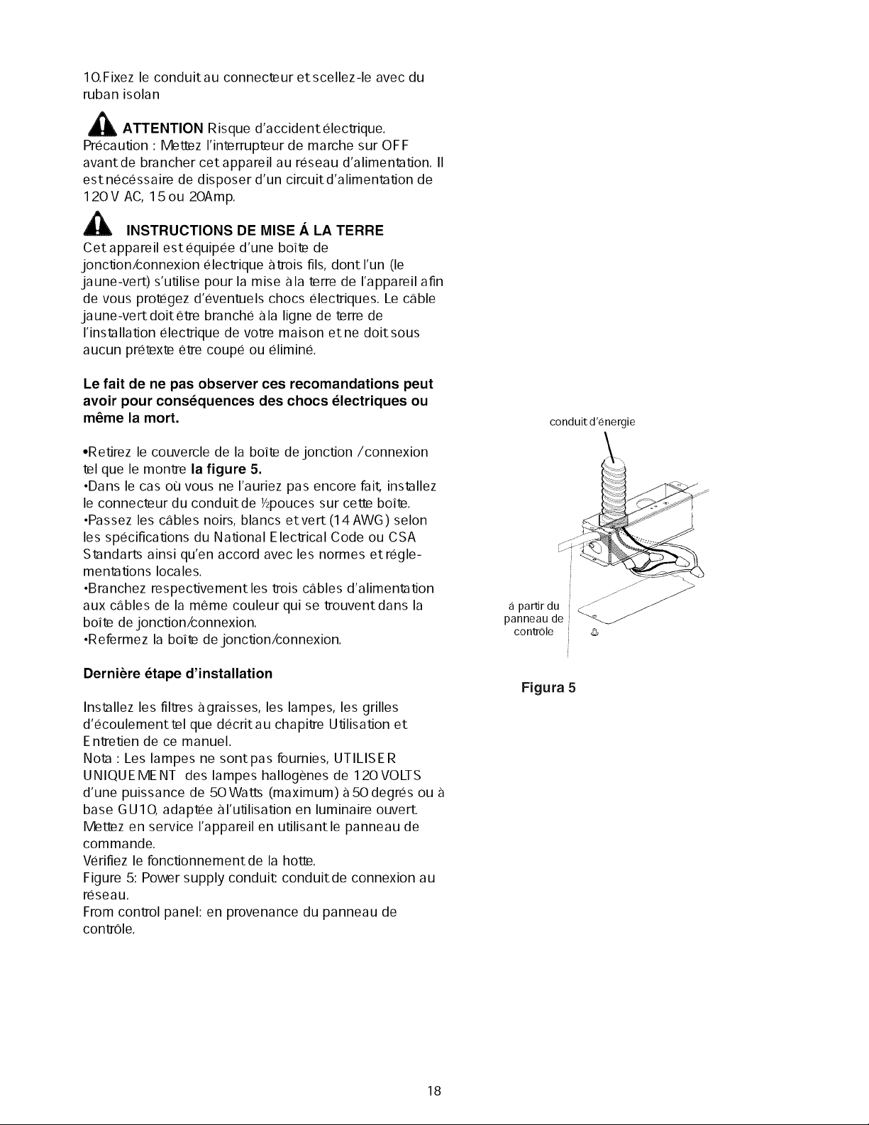
•Retirez le couvercle de la boite dejonction/connexion
tel que le montre la figure 5.
,Dans le cas ou vous ne I'auriez pas encore fail installez
le connecteur du conduitde _hpoucessur cet_ boite.
,Passez les c_ibles noirs, blancs etvert (14 AWG) selon
les specifications du National Electrical Code ou CSA
Standarts ainsi qu'en accord avec les normes etregle-
mentations Iocales.
,Branchez respectivementles trois c_ibles d'alimentation
aux c_ibles de la meme couleur qui se trouventdans la
boite dejonction/connexion.
,Refermez la boite de jonction/connexion.
conduit d'energie
J_
apo rdu
panneau de
conlzole
Derniere etape d'installation
Installez les filtres agraisses, les lampes, les grilles
d'ecoulementtel que decritau chapitre Utilisation et
Entretien de ce manuel.
Nota : Les lampes ne sontpas fournies, UTILISER
UNIQUE MENT des lampes hallogenes de 120 VOLTS
d'une puissance de 50Watts (maximum)a 50degres ou
base GUIO, adaptee al'utilisation en luminaire ouverL
Metl_z en service I'appareil en utilisantle panneau de
commande.
Verifiez le fonctionnementde la hotly.
Figure 5: Power supply conduit conduitde connexion au
reseau.
From control panel: en provenance du panneau de
contrOle.
Figura 5
18
Page 19

INSTRUCCIONES IMPORTANTES DE SEGURIDAD
Lea todas las instrucciones antes de utilizar el dispositivo.
LEA Y GUARDE ESTAS INSTRUCCIONES
ADVERTE C
PARA REDUCIR EL RIESGO DE INCENDIO,
DESCARGA ELECTRICA, O DANO A PERSO-
NAS, OBSERVE LO SIGUIENTE:
A. Utilice esta unidad solamente en la forma
especificada por el fabricante. Si tiene preguntas
contacte al [abricante.
B. Antes de dar mantenimiento o limpiar la
unidad, apague el interruptor en el panel de
control y asegure el panel de servicio para evitar
que el interruptor sea encendido accidental-
mente. Si el panel de servicio no puede ser
asegurado coloque una gran advertencia, tal
como una etiqueta, en el panel de servicio..
C. El trabajo de instalacion y el cableado
electrico deben ser hechos por persona(s)
calificada(s) de acuerdo con todos los codigos y
estandares aplicables, incluyendo las relaciona-
das a incendios.
D. Se requiere suficiente aire para una com-
bustion apropiada y exhalacion de gases a
traves del escape (chimenea) o equipo de
quema de combustible para prevenir regresos.
Siga la guia de los fabricantes del equipo de
calentamiento y los estandares de seguridad
tales como los publicados en la Asociacion
Nacional de Proteccion del Fuego. (NFPA), la
Sociedad Americana de Ingenieros en Calenta-
miento, RefrigeraciOn y Aire Acondicionado
(ASHRAE), y las autoridades locales.
E. Cuando corte o haga agujeros en la pared o el
techo, no dafie el cableado electrico y otros
dispositivos escondidos.
F. Los sistemas conductuales deben siempre
dirigirse al exterior.
PRECAUCION
PARA VENTILACION GENERAL SOLA-
MENTE. NO UTILICE MATERIALES O
VAPORES EXPLOSIVOS O PELIGROSOS.
PRECAUCION
Para reducir el riesgo de incendio y exhalar el
aire propiamente, asegurese de enviar los ductos
de aire al exterior- no hacia dentro de las pare-
des, techos, aticos, espacios sin uso o garajes.
ADVERTENCIA
PARA REDUCIR EL RIEGO DE FUEGO,
UTILICE SOLO DUCTOS DE METAL.
Instale esta campana de acuerdo a todos los
requerimientos especil:icados.
ADVERTENClA
Para reducir el riesgo de fuego o descarga
electrica, no use esta campana con ningun
aparato de control de estado de velocidad
externo.
OPERACION
a. Siempre deje las parrillas de seguridad y los
filtros en su lugar.
Sin estos componentes, los ventiladores en
operaciOn pudieran atrapar pelo, dedos y trapos
sueltos.
Los fabricantes se deslindan de toda responsabi-
lidad en caso de falla al observar las instruccio-
nes dadas aqui para la instalacion, manten-
imiento y uso adecuado del producto. El fabri-
cante tambien se deslinda de toda responsabili-
dad por dafio debido a negligencia y la garantia
de la unidad expira automaticamente debido a
mantenimiento inadecuado.
Esta unidad esta fabricada para uso interior solamente, No utilice esta unidad en el exterior
19
Page 20

INSTRUCCIONES DE SEGURIDAD
ReadAll Instructions Before Using the Appliance.
READAND SAVETHESEINSTRUCTIONS
IMPORTANTES
Requerimientos eldctricos
IMPORTANTE
Observe todos los codigos y mandatos en
USO.
Es responsabilidad del cliente:
Contactar un instalador electrico calificado.
Para asegurar que la instalacion electrica es
adecuada yen conformidad con el Codigo
Electrico National, ANSI/NFPA 70
ultima edicion _, o Estandares CSA
C22.1-94, Codigo Electrico Canadiense,
Parte 1 y C22.2 No.0-M91 - ultima edition _
y todos los codigos y ordenanzas locales.
Si los codigos Io permiten y un cable de
aseguramiento separado es utilizado,
Se recomienda que un electricista calificado,
determine si el camino a tierra es adecuado.
No haga tierra a un tubo de gas.
Cheque con un electricista calificado si usted
no esta seguro si la campana esta propia-
mente instalada.
No tenga un fusible en el circuito neutral o
tierra.
IMPORTANTE
Guarde las instrucciones de instalaci0n
para uso del inspector electrico.
La campana debe ser conectada solamente
con cable de cobre.
La campana debe ser conectada directa-
mente a la caja de desconexion (o interrup-
tor del circuito) a traves de conductos elec-
tricos de metal.
Las medidas del cable deben de confor-
marse a los requerimientos del Codigo
Electrico Nacional ANSI/NFPA 70 --01tima
edicion _, o Estandares CSA C22.1-94,
Codigo Electrico Canadiense, Parte 1 y
C22.2 No.0-M91 - 01tima edicion _ y todos
los codigos y ordenanzas locales.
A U.L.- o C.S.A.- Un conector debe ser
provisto en cada terminal del conducto de la
fuente de alimentacion (en la campana yen
la caja de uniones).
Como referencia se puede consultar:
National Fire Ftotection Association Batterymarch
Park
Quincy, Massachusetts 02269
_ CSA International 8501 East Pleasant Valley Road
Cleveland, Ohio 44131-5575
2O
Page 21

Partes Incluidas con su Campana
• Ensamblaje de Campana con extractores ya
instalados
• Filtros de grasa
• Bandejas de goteo
• Instrucciones de uso / cuidado e instalacion
• Bolsas a la medida con:
• Sujetadores de las Bandejas de goteo y
arandelas de plastico y perillas
4 Arandelas
6 anclas de pared
2 Ganchos con la regulacion de tornillos
6 Tornillos 5X35
4 tornillos para la transici6n 2,9,6,5
Accesorios opcionales
Cubiertas de ductos
Kit de recirculacion disponible solo para el
modelo HPWB30.
Partes no incluidas en su campana
• Cinta de ducto
• 1/2" Conductor
• Cables
• Ductos redondos
• Abrazaderas
_1_ PRECAUCl6N! Los [ocos no se
proveen, use SOLO luz de halogeno de 120 Volt, 50
Watt (maximo) 50° o una base GU10,
Adecuada para uso en iluminacion abierta,,
• 4 tornillos de madera #10 para instalacion abajo de
un gabinete,
• Herramientas requeridas
• Navaja y desarmador Phillips
• Lapiz y cinta de medir
• Tijeras de metal (en algunas aplicaciones)
• Taladro electrico
• Serrucho
• Tenazas
• Nivel
• Resanador
• Lampara
• Cable
• Anteojos de seguridad
• Guantes
• Escalera
INSTALANDO LA CAMPANA
• Para una mayor expulsion de aire, utilice
conductos rectos o menos codos como sea
posible,
PRECAUClON: Ventile la unidad hacia
afuera de edificios solamente,
• Se requiere una persona para instalaciOn,
En promedio se requieren 2 horas para la
instalacion (sin considerar cortes necesarios en
la pared o el gabinete, instalacion de ductos,
conexiones electricas o conductuales),
Pasos de instalaci6n:
11 pasos de instalacion se requieren para
ambos metodos de instalacion
Pasos para instalacion en la pared o en un
gabinete:
• La campana se ajusta con tornillos y anclas
aplicables a cualquier superficie, consulte un
instalador calificado, cheque si se adecuan
perfectamente a su pared/gabinete,
• No utilice ductos flexibles
• Instalaciones en CLIMA FRIO deben tener
un amortiguador adicional para minimizar el
regreso de aire fr|o y un freno termico no
metalico para minimizar la conduccion de
temperaturas exteriores como parte del trabajo
de conducciOn, El amortiguador debe estar de
lado del aire fr|o del freno termico, El freno
debe estar tan pegado como sea posible a
donde el conducto entra a la porcion calen-
tada de la casa,
•Aire tratado: Codigos de construccion local
pueden requerir el uso de Aire tratado cuando
se utilice Sistemas de ventilacion mayores a
los especificados en el CFM,
El CFM especificado var|a de Iocalidad en
Iocalidad,
Consulte su especialista en HVAC para
requerimientos espec|ficos en su area,
21
Page 22

• Instalaci6n tipica
La altura del mostrador a la base de lacampana es de 24"a 30".
No se recomienda usar estas campanas en asadores.
I. Escoja opciones de ventilaci6n
La campana est_ diseffada para utilizarse en descargas verticales como se muestra abajo.
Nota: ver tambi6n la Fig. I-2-3 para la preparaci6n del gabinete.
Instale un conducto de I/2"desde el panel de servicio Io suficientemente largo para alcanzar la campana una vez que se
ha instalado. La energia debe ser de 120V AC, 60Hz. 15 o 20 A.
Techo
_Deflector
L_m
Cam
T
30" a 36"
Ejemplos de posible intalaci6n.
Ductos Redondos.
Transition
Blower
_Filtros de Carb6n.
Filter
Techo Transici6n
L_mpara Extractor.
X
Campana Filter
_1r _ Filtros de Carb6n
30" a 36"
Accesorio opcional - Kit de recirculaci6n
22
Page 23

AJUSTES DE DUCTOS
Utilice esta tabla para computar
los largos posibles m&-dmos que
van hacia el exterior.
IVota:No exceda los las equivalen-
cias en largos m_ximos permiti-
das.
Largo m_ximo recomendado para
estas campanas: 150 pies.
Acerca de ductos fle.-dble:
Si se utiliza metal flexible, todos los
valores equivalentcs en pies en la
tabla &ben ser duplicados. E1 ducto
de metal flexible debe ser recto y
liso y extenderse mnto como sea
posible.
NO utilice ductos de pl(istico
flexible.
Nota: Cualquier sistema de ventilaci6n en
casa, tales como las campanas, puede
interrumpir el flujo correcto de aire de
combusti6n y exhalaci6n requerido por
chimeneas, estufas de gas, calentadores de
agua de gas y otros sistemas ventilados
naturalmente. Para minimizar la posibili-
dad de interrupci6n de tales sistemas
ventilados naturalmente, siga las instruc-
ciones del fabricante o los estandares de
seguridad tales como los publicados por
NFPA y ASHRAE.
%as campanas se suplen
con una transici6n redonda
de 10"
Una transici6n se requiere
para otras medidas.
Nota:
La salida en la parte alta de
la campana es de 1/8" x 8".
Q
©
10"redondo
a8"redondo
Redondo,
recto
3-1/4" x 10"
3-1/4" x 12 "
recto
codo 90 °
codo 45°
3-1/4" x 12"
3-1/4" x 10"
codogO °
3-1/4" x 10"
3-1/4" x12"
codo 45°
3-1/4" x 10"
3-1/4" x 12"
codo piano 90°
transicidn redonda 10"
de3-1/4" x 10" o
3-1/4" x 12"
3-1/4" x 10" o
3-1/4" x 12" a
10"
transicidn redonda de
10"3-1/4" x 10"
codo 90° de 3-1/4" x 12"
transiciones de
3-1/4" x 10"
3-1/4" x 12" o
redonda de 10"
codo de 90 °
Cubierta de pared
con amortiguador
Cubierta de pared
con amortiguador de
3-1/4" x 10"
3-1/4" x 12"
Cubierta de techo.
5ft.
lft.
(por pie de largo)
lft.
(por pie de largo)
8" Dia. 17 ft.
10" Dia. 24 ft .
8" Dia. 10 ft.
10" Dia. 14 ft.
lSft.
14ft.
8ft.
9ft.
33 ft.
36 ft.
9ft.
6ft.
16ft.
13ft.
9ft.
8ft.
8" Dia. 32 ft.
10"Dia. 41ft.
24 ft.
26 ft.
23
Ducto Total
Page 24

Porrazonesdeseguridad,losductosdebenserventiladosdirectamentealexterior(nohaciaun_tico,debajodelacasa,
haciaelgarageocualquierespaciocerrado).
Mantengalosductostancortosyrectoscomoseaposible.
Losaditamentosalducto(codosy transiciones)reducenlaeficienciadelflujodeaire.
Loscodostraserosy"S"tienenundesempe_omuypobreynosonrecomendados.Losductosrectosalaentradadel
extractorofrecenelmejorresultado.
Unatransici6nalductodesdeelextractorintegralounatransici6nremotaalductotancercanaaltuboaspersorcomo
seaposibleesmejor.
Enordendepreferencia,utilice:
1ro.ductoredondode10"
2do.ductoredondode8"
3ro.ducto3-1/4"x14"
4to.ductoredondode7"
5to.ductode3-1/4"xI0"
6to.ductoredondode6"
Elusodemetalflexibleredondopuedeserutilizadosolamentecuandonoexistaottoducto.Limitesuusoa
medidascortasynoaplasteenlasesquinas.
1.Prepareelductoyloscortesdeconducci6n,vealasfiguras
1y2siesnecesario.
[ Model 30" 36"
Fren_e degabinete X 2 3/4" 4 9/]6"
Fondo de gabinete
12"
t
6-1/4"J
Pared
Figura 1
CL
Anchode Campana
2.Ensamble de la transici6n de 10":
Latransici6n provista con la campana se coloca encima de la
parte de arriba de 6sta.
No instale la transici6n hasta que la campana haya sido fijada
en el gabinete.
a. Coloque la pieza de transici6n sobre lasalida de la campana
y asegOrela con 4 tomillos provistos.(Figura 3)
b. Envuelva todas lasuniones (transici6n met_lica y campana)
con cinta selladora para un sellado a prueba de aire.
c. Remueva la cinta que sostiene el amortiguador.
salida de la cam
Figura 2
Figura 3
Transici6n
23-1/8"
Tornillos (4)
24
Page 25

Instalaci6n a pared
Nota: vea abajo si se prefiere instalaci6n en gabinete.
3. Despu_s que la altura de la instalaci6n de la campana
ha sido establecida dibuje una linea horizontal a una
distancia sobre la cubierta de la estufa igual a la altura
deseada de la instalaci6n de la campana m_s 7- I/2". Vea
Figura 4a.
4.Encuentre la linea media de la cubierta de la estufa.
Dibuje una linea vertical a Io largo de esta linea central
hacia la linea horizontal dibujada en el paso I y dibuje
una linea vertical a la izquierda y derecha a una distancia
de 12-5/8" para determinar la localizaci6n de los ganchos
de montaje enviados con la campana.
5.Coloque dos ganchos sobre la pared para colgar la
campana a trav_s de las ranuras proporcionadas (2 anclas
de pared + 2 ganchos + 2 tornillosSx3S).
6. Colocque el duct© de I 0", Io suficientemente largo
para alcanzar la transici6n una vez que la campana ha
sido instalada m_s 1 I/2"pulgadas para conectar al duct©.
Fije el duct© a la transici6n con tornillos y con cinta de
sellado.
7.Remueva I o 2 terminaciones e instale un conector de
I/2"en la caja de conexi6n
8.Cuelgue la campana y ajuste su posici6n a trav_s de los
tornillos en los ganchos.
9.Fije la campana en 4 puntos adicionales, 2 en la parte
de arriba, 2 en la parte de abajo (utilice 2 anclas de pared
+ 4 arandelas + 4 tornillos 5x35).
ANCHODECAMPANADIM. "W" DIM. "K" DIM. "Z"
Tabla 3
Figura 4a
orificios para
caja de conexi6n
7 1/2' l
30" 29 - I/8" 2 - I/2" 7 - 1/16"
36" 35 - 1/16" 2 - I/2" 7 - 1/16"
Slots
laterales x4
W
tornillos
inferiores,
ranuras
cuadrados.
Tornil!os
Instalaci6n en gabinete:
Nota: vea arriba si se prefiere instalacibn montada en la
pared
Nota: distancias en la Tabla 3.3.
Encuentre la linea central de la parte baja del gabinete.
Dibuje una linea a Io largo de esta linea central de atr_s
hacia adelante del gabinete.
Vea tambi_n la Figura 4b.
4.Dibuje dos lineas, una a una distancia K de la pared y la
otra a una distancia Z de la linea previa.
Marque 4 punt©s, dos a Io largo de cada linea a una distan-
cia de la mitad de W de la linea central, para determinar las
posiciones de los tornillos.
5.Coloque 4 tornillos en la parte baja del gabinete sin
apretar completamente per© deje espacio de aproximada-
mente 1/2"de la parte baja de la superficie del gabinete y
los tornillos.
6. Coloque el duct© de 10", Io suficientemente largo para
alcanzar latransicibn una vez que la campana ha sido
instalada m_s 1 1/2" pulgadas para conectar el duct©.
Quite 1de los 2 pivotes e instale el conector de 1/2"en la
caja de conexibn.
8. Cuelgue la campana en los tornillos por las ranuras
laterales provistas en Io alto de la campana. Apriete los
cuatro tornillos. Nota: Si es posible fije la campana en cuatro
puntos adicionales (2 en la parte de arriba, 2 en la parte de
abajo).
9. De adentro del gabinete fije la transicibn en la salida de
arriba.
Fije el duct© a la transici6n y selle con cinta.
25
© ©
Gancho para _ Tomillo de
instalacion a intalaci6n a
_. / pared. _ fond© de
"_ 25:3/16" _f gabinete
7 _2"-_12 5'8" !,2 5'8"-_ J_Torni,,o de
'_ CL ajuste,
Fond© de gabinete.
Figura 4b
_K
Page 26

Para ambos metodos de instalaci6n:
10.Cableado de la CAMPANA:
_bb ADVERTENCIA:
Para Evitar un Choque Electrico
apague la fuente de poder en el panel de servicio antes
de cablear esta unidad.
Circuito requerido 120 VAC, 15 o 20 Amp
INSTRUCCIONES PARA TIERRA ELECTRICA
ESTE EQUIPO ESTA SUPLEMENTADO CON UNA CAJA
ELECTRICA CON 3 CABLES, UNO DE LOS CUALES
(VERDE/AMARILLO) SIRVE PARA HACER TIERRA.
'_ ADVERTENCIA:
PARA PROTEGERLE CONTRA DESCARGAS ELECTRI-
CAS, ESTE DEBE SER CONECTADO AL CABLE
TIERRA DE SU SISTEMA ELECTRICO CASERO, Y NO
DEBE SER REMOVlDO O CORTADO BAJO NINGUNA
CIRCUNSTANCIA.
Cable de
energla
Una falla al hacer estas acciones puede resultar en
muerte o descarga electrica.
• Quite la cubierta de la caja-j como se muestra en la
Figura 5.
• Si no se ha hecho, instale un conector conductual de
112"en la caja-j.
• Coloque los cables negro, blanco y verde (#14 AWG) de
acuerdo al Codigo Electrico Nacional o los estandares
CSA y codigos y ordenamientos locales.
• Conecte los cables negro, blanco y verde de la fuente de
poder a los cables negro, blanco y verde/amarillo en la
caja-j respectivamente.
• Cierre la cubierta de la caja-j.
Pasos finales de instalaciOn
11.Instale los filtros de grasa, lamparas y bandejas de
goteo, como se describe en la secciOn de Uso & Cuidado
de este manual.
Nota: Las lamparas no se suministran, use SOLAMENTE
120
Volt, 50 Watt (maximo) 50° en luz de halogeno hecha
para una base GUl0,
adecuada para usar en iluminacion abierta
Encienda la corriente en el panel de servicio.
........
control
Delpanel de __
Figura 5
i
._..__2, ....
26
 Loading...