

Page 1
PLEASE READ ENTIRE INSTRUCTIONS BEFORE PR OCEEDING.
INSTALLATION MUST COMPLY WITH ALL LOCAL CODES.
IMPORTANT: Save these instructions for the Local Electrical Inspector’s use.
INSTALLER: Please leave these Installation Instructions with this unit for the owner.
OWNER: Please retain these instructions for future reference.
IMPORTANT SAFETY INSTRUCTIONS
READ AND SAVE THESE INSTRUCTIONS
WARNING: TO REDUCE
THE RISK OF FIRE, ELECTRIC
SHOCK, OR INJURY TO PERSONS, OBSERVE THE FOLLOWING:
CAUTION: FOR GENERAL
VENTILATING USE ONLY. DO
NOT USE TO EXHAUST HAZARDOUS OR EXPLOSIVE MATERIALS OR VAPORS.
A. Use this unit only in the manner
intended by the manufacturer. If you
have questions, contact the manufacturer.
B. Before servicing or cleaning unit,
switch power off at service panel and
lock the service disconnecting means
to prevent power from being switched
on accidentally. When the service disconnecting means cannot be locked,
securely fasten a prominent warning
INSTALLATION INSTRUCTIONS
MODELS H/HT/HB WALL HOOD
FOR RESIDENTIAL USE ONLY
device, such as a tag, to the service
panel.
C. Installation work and electrical
wiring must be done by qualified persons in accordance with all applicable
codes & standards, including fire-rated
construction.
D. Sufficient air is needed for proper
combustion and exhausting of gases
through the flue (chimney) of fuel burning equipment to prevent backdrafting.
Follow the heating equipment manufacturers guideline and safety standards
such as those published by the National Fire Protection Association
(NFPA), the American Society for Heating, Refrigeration and Air Conditioning
Engineers (ASHRAE), and the local
code authorities.
E. When cutting or drilling into wall
or ceiling, do not damage electrical
wiring and other hidden utilities.
F. CAUTION: To reduce risk of
fire and to properly exhaust air, be
sure to duct air outside. Do not vent
exhaust air into spaces within walls,
ceilings, attics, crawl spaces or garages.
G. WARNING – TO REDUCE
THE RISK OF FIRE, USE ONLY METAL
DUCT WORK.
H. Install this hood in accordance
with all requirements specified by the
manufacturer of your cooktop/range.
I. This appliance has a polarized plug
(one blade wider than the other). To
reduce the risk of electric shock, this
plug is intended to fit in a polarized
outlet one way. If the plug does not fit
fully in the outlets, reverse the plug. If
it still does not fit, contact a qualified
electrician. Do not attempt to defeat
this safety feature.
WARNING - TO REDUCE THE RISK OF A RANGE
TOP GREASE FIRE:
A. Never leave surface units unattended at high settings.
Boilovers cause smoking and greasy spillovers that may ignite.
Heat oils slowly on low or medium settings.
B. Always turn hood ON when cooking at high heat or when
cooking flaming foods.
C. Clean ventilating fans frequently. Grease should not be
allowed to accumulate on fan or filter.
D. Use proper pan size. Always use cookware appropriate
for the size of the surface element.
WARNING: - TO REDUCE THE RISK OF INJURY
TO PERSONS IN THE EVENT OF A RANGE TOP
GREASE FIRE, OBSERVE THE FOLLOWING:
A. SMOTHER FLAMES with a close-fitting lid, cookie
sheet, or metal tray, then turn off the burner. BE CAREFUL
TO PREVENT BURNS. If the flames do not go out
immediately, EVACUATE AND CALL THE FIRE
DEPARTMENT.
B. NEVER PICK UP A FLAMING PAN
C. DO NOT USE WATER, including wet dishcloths or
towels – a violent steam explosion will result.
D. Use an extinguisher ONLY if:
1) You have a Class ABC extinguisher, and you already
know how to operate it.
2) The fire is small and contained in the area where it
started.
3) The fire department is being called.
4) You can fight the fire with your back to an exit.
PAGE 1
– You may be burned.
Page 2

Parts included with your Hood:
Hood Canopy Assembly
Rough-in Plate
* Transition/Damper for ducting
Mounting Screws (8, #10 x 1") - may
not need all screws (depending
on hood size)
Installation Instructions
Care & Use Manual
Registration Card
Filters (3 or 4 depending on hood size)
Hex nuts (10 pieces)
Blower Mounting Bracket
To be purchased separately:
* NOTE: The 19-11-943 (equiva-
lent to VM410) Ventilator and
Transition are included with all
HB Model hoods.
• Ventilator: choose one of the
following:
* VM410 – 400CFM, integral
ventilator.
VTN600Q – 600 CFM, integral
ventilator.
VTR600R – 600 CFM, remote
ventilator.
VTR1000Q – 1000CFM, remote
ventilator.
• H and HT models require Transi-
tion HTR8 or HTR10.
• For integral ventilator installations,
choose one of the following exhaust outlets:
– RJ310 (roof outlet)
– WC310 (wall outlet)
– WC8
– WC10
• Halogen Bulbs (2), size R20, 50
watt maximum.
• Duct Tape, 2" wide
• Wall Anchors (if needed)
• 1/2"Diameter Conduit
• Keep Hot Shelf Accessory-KHS
(Optional)
• Wire Nuts
• Keep hot lamps (2) Size R40
250W maximum (H/HT Hoods
only)
• Tools Needed:
Phillips Screw Driver
3/8" Hex Socket Driver
1-1/2" Drill bit (Wood)
Electric Drill
Hammer
Pencil
Level
Saber Saw
CONSIDERATIONS BEFORE INSTALLING HOOD
1. For efficient air flow exhaust, use a
straight run or as few elbows as
possible.
2. Do not use flex ducting.
3. COLD WEATHER installations
should have an additional backdraft
damper installed to minimize backward cold air flow and a nonmetallic thermal break to minimize conduction of outside temperatures as part of the ductwork.
PAGE 2
The damper should be on the cold
air side of the thermal break. The
break should be as close as possible to the location where the
ducting enters the heated portion
of the house.
Page 3
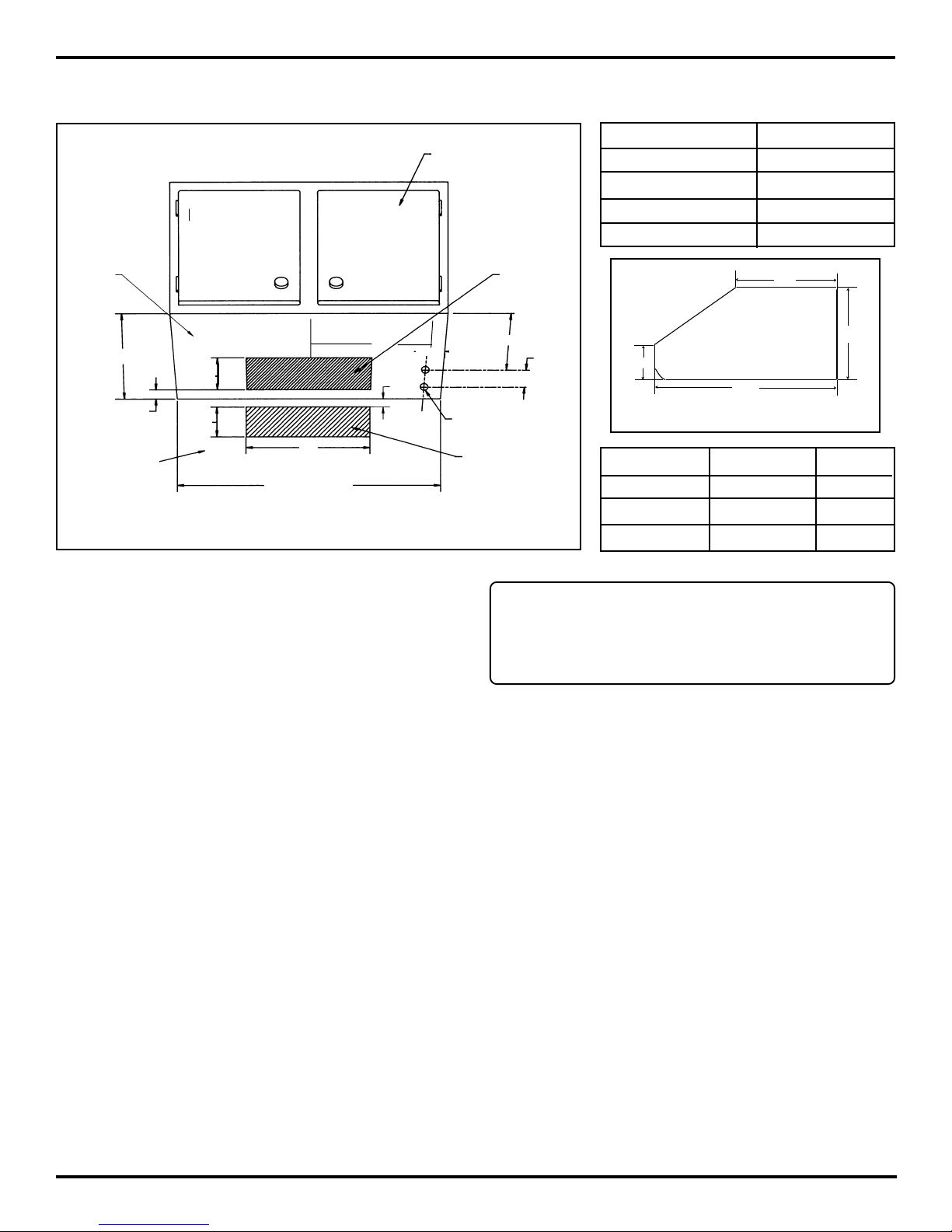
CABINET OR SOFFIT PREPARATION
Cabinet Front
Bottom of
Cabinet or
Soffit
Cabinet
Vertical
Discharge
HOOD LENGTH DIM. "A"
30" 13-11/32"
36" 15-1/2"
42" 16"
48" 17-1/2"
12"
➝
12"
4-1/2"
1/2"
4-1/2"
"C"
Rear Wall
Hood Length
"A"
➝
1/2"
Figure 1
TYPICAL INSTALLATION
The hoods are designed for either vertical or horizontal
discharge as shown in Figure A and B respectively.
The recommended height from the countertop to the
bottom of the hood is 30" to 36". These hoods are not
recommended to be used over solid fuel fire barbecues.
8-1/2"
1-7/8"
1-1/2"Dia. Holes
Optional Rear
Discharge
Note: It is important to select the ventilator to
be used before cutting the duct opening on the
cabinet or wall.
"B"
4"
22"
Figure 2
Hood Type Height "B" DIM. C
H series 10" 18"
HB series 10" 13"
HT 18" 18"
PAGE 3
Page 4

Round Duct
Soffit
Rough-in Plate
Heat Lamp
Hood
Back Splash
(with Warming Shelf)
Transition
Ventilator
(VTN600Q)
Filter
Rough-in Plate
Heat Lamp
Hood
Soffit
Filter
➝
Outside
Wall
Wall
Cap
➝
Transition
Ventilator
30" to 36"
Cooktop
Figure A – Vertical Discharge
INSTALL THE ROUGH-IN PLATE:
Note: Before installing the rough-in plate to the bottom of
the cabinet or soffit, make sure that the cabinet or soffit is
level.
1. Detach the rough-in plate from the hood assembly by
removing three shipping screws on the back and three
shipping screws on the top of the hood assembly.
2. Remove the proper knockout panels on the rough-in
plate for the selected ventilator. The rough-in plate is
reversible to allow either horizontal or vertical discharge for both knockout panels.
3. Attach the rough-in plate to the cabinet or wall with the
mounting screws (#10 x 1") provided. Use all holes
provided in the rough-in plate. (Use wall anchors as
necessary on drywalls.)
30" to 36"
Back Splash
(with Warming Shelf)
Cooktop
Figure B – Horizontal Discharge
Longer Bracket
(Provided with H/
HT Hoods)
7-1/2"
8"
12-3/4"
Figure C
H/HB/HT HOOD SERIES
Hex Nut
VM410
INSTALL THE INTEGRAL VENTILATOR
MODEL VM410 (H and HT only):
Note: For HB series hood the ventilator is shipped and pre
mounted to the rough-in plate. For H/HT series hood
the VM410 is to be purchased separately.
1. Remove and discard the Z-shape bracket from the
VM410.
2. Remove the blower mounting bracket and replace with
a longer bracket provided with the H/HT hood. See Fig.
C.
Figure D
3. Insert one end of the blower mounting bracket into the
ventilator mounting channel located on the rough-in
plate, and slip the other end over the weld stud on the
rough-in plate. Secure assembly with the hex nut provided with the hood. See Fig. D.
PAGE 4
Page 5

INSTALL THE INTEGRAL VENTILATOR
MODEL VTN600Q:
INSTALL THE REMOTE VENTILATOR
MODEL VR600, VTR600R OR VTR1000Q:
Insert one end of the blower mounting bracket into the
ventilator mounting channel located in the rough-in plate,
and slip other end of bracket into the weld stud on the
rough-in plate and tighten it with the hex nut provided with
the hood. See Fig. D.
DUCTING CONNECTION:
FOR INTEGRAL VENTILATOR MODEL
VM410, 19-11-943 (HB Hoods):
1. Attach the transition (3-1/4" x 10") provided to the top
of the rough-in plate, using the two shipping screws.
Make sure the knockout on the rough-in plate is removed. Seal all joints between the rough-in plate and the
transition with duct tape.
2. Install 3-1/4" x 10" duct from the transition to the wall
or roof (use roof exhaust outlet RJ310 or wall exhaust
outlet WC310, purchased separately).
FOR INTEGRAL VENTILATOR MODEL
VTN600Q:
1. Attach the transition Model # HTR8 (purchased sepa-
rately) to the top of the rough-in plate. Make sure the
proper knockout on the rough-in plate is removed. Seal
all joints between the rough-in plate and the transition
with duct tape.
For installing the remote ventilator on the roof or side
wall, refer to the Installation Instructions provided with the
ventilator.
2. Install 8" round duct from the HTR8 transition to the
side wall (use wall cap Model # WC8, purchased
separately).
FOR REMOTE VENTILATOR MODEL
VTR600R, VTR1000Q:
1. For the VTR600R, attach transition Model HTR8 (pur-
chase separately) or for VTR1000Q attach transition
Model HTR10 (purchase separately), to the top of the
rough-in plate. Make sure the proper knockout on the
rough-in plate is removed. Seal all joints between the
rough-in plate and the transition with duct tape.
2. Use 8-inch round duct for the VTR600R or10-inch
round duct for the VTR1000Q. Install duct from the
transition to the remote ventilator.
ELECTRICAL CONNECTION:
1. Install three wires: black, white and green (#16 AWG)
in 1/2" conduit from the service panel to the hood
junction box. Power supply must be rated for 120v,
60Hz, 15 amps (minimum)
2. Remove the knockout and install the strain relief (conduit) connector in the rough-in plate hole.
3. Remove the junction box cover from the rough-in plate.
Connect black wire # 9 to power supply black wire,
white wire # 5 to power supply white wire, and green
wire # 18 to power supply green wire. See wiring
diagram on page 7.
PAGE 5
Page 6

WIRING TO INTEGRAL VENTILATOR
MODEL VM410, VTN600Q:
1. Plug the power cord from the ventilator motor to the
receptacle located inside the hood assembly. See wiring
diagram.
2. Install the junction box on the rough-in plate.
WIRING TO REMOTE VENTILATOR
MODEL VTR600R, VTR1000Q FOR H AND
HT HOOD ONLY:
1. Remove the knockout and install the strain relief (conduit) connector on the rough-in plate hole. Run three
wires black, white and green (#16 AWG) in 1/2" conduit
from the remote ventilator to the hood junction box.
INSTALL HOOD ASSEMBLY:
1. Install the hood assembly to the rough-in plate by
aligning the weld studs on the rough-in plate with slotted
holes on the back of the hood assembly.
2. Connect wires from step 1 above to the remote ventilator wires using color codes (black to black, white to
white, and green to green). See wiring diagram on Page
7.
Important: Individually cap the blue and red wires in
the remote ventilator wiring compartment with wire
nuts.
3. Connect the wires from Step 1 to the hood assembly.
Wiring: Black wire to red wire #19, white wire to white
wire #5, and green wire to green wire #18. See wiring
diagram on Page 7.
4. Reinstall the junction box on the rough-in plate.
4. Insert filter into the bottom rear slot of the hood
assembly and fully compress the spring.
5. Holding the filter by the handle, snap it into place.
2. Using the hex nuts provided secure the hood assembly
to the rough-in plate.
3. Install two halogen bulbs, size R20, 50 watts maximum.
Also install two heat lamp bulbs, size R40, 250 watts
maximum for H and HT Hood. Bulbs are not provided.
PAGE 6
Page 7

WIRING DIA GRAMS FOR H, HT AND HB HOODS
WIRING DIAGRAM
HB HOODS
19-11-987B
WIRING DIAGRAM
H AND HT
HOODS
19-11-928C
PAGE 7
Page 8

Thermador reserves the right to change specifications or design without notice. Some models are certified for use in Canada.
Thermador is not responsible for products which are transported from the United States for use in Canada. Check with
your local Canadian distributor or dealer. Thermador, 5551 McFadden Avenue, Huntington Beach, CA 92649.
FILE # E21958
5551 McFadden Avenue • Huntington Beach, CA 92649 • 800/735-4328
ECO# 71532 • 19-11-930F • © Thermador Corporation,1998 • Litho in U.S.A. 9/99
PAGE 8
 Loading...