

Page 1

CEM
COOK TOP
INSTALLA
TION
INSTRUCTIONS
Page 2

Table of Contents
Safety . . . . . . . . . . . . . . . . . . . . . . . . . . . . . . . . . . . . . .1
IMPORTANT SAFETY INSTRUCTIONS . . . . . . . . . . . . . . . . . . . . . . . . . . . . . . 1
Installation . . . . . . . . . . . . . . . . . . . . . . . . . . . . . . . . . .2
Before You Begin . . . . . . . . . . . . . . . . . . . . . . . . . . . . . . . . . . . . . . . . . . . . . . . . 2
Tools and Parts Needed . . . . . . . . . . . . . . . . . . . . . . . . . . . . . . . . . . . . . . . . . . . . . . . . . . . . . . . . . . . . . . . 2
Parts Included . . . . . . . . . . . . . . . . . . . . . . . . . . . . . . . . . . . . . . . . . . . . . . . . . . . . . . . . . . . . . . . . . . . . . . . 2
Overall Dimensions . . . . . . . . . . . . . . . . . . . . . . . . . . . . . . . . . . . . . . . . . . . . . . . . . . . . . . . . . . . . . . . . . . 2
Cabinet Requirements . . . . . . . . . . . . . . . . . . . . . . . . . . . . . . . . . . . . . . . . . . . . . . . . . . . . . . . . . . . . . . . . 2
Countertop Requirements . . . . . . . . . . . . . . . . . . . . . . . . . . . . . . . . . . . . . . . . . . . . . . . . . . . . . . . . . . . . . 3
Power Requirements . . . . . . . . . . . . . . . . . . . . . . . . . . . . . . . . . . . . . . . . . . . . . . . . . . . . . . . . . . . . . . . . . 4
Installation Procedure . . . . . . . . . . . . . . . . . . . . . . . . . . . . . . . . . . . . . . . . . . . . . . . . . . . . . . . . 4
Seal with Foam Tape . . . . . . . . . . . . . . . . . . . . . . . . . . . . . . . . . . . . . . . . . . . . . . . . . . . . . . . . . . . . . . . . . 4
Prepare the Countertop . . . . . . . . . . . . . . . . . . . . . . . . . . . . . . . . . . . . . . . . . . . . . . . . . . . . . . . . . . . . . . . 4
Secure Cooktop to Countertop . . . . . . . . . . . . . . . . . . . . . . . . . . . . . . . . . . . . . . . . . . . . . . . . . . . . . . . . . . 5
Electrical Connection . . . . . . . . . . . . . . . . . . . . . . . . . . . . . . . . . . . . . . . . . . . . . . . . . . . . . . . . . . . . . . . . . 6
Before Calling Service . . . . . . . . . . . . . . . . . . . . . . . . . . . . . . . . . . . . . . . . . . . . . . . . . . . . . . . . 6
Product Data Plate . . . . . . . . . . . . . . . . . . . . . . . . . . . . . . . . . . . . . . . . . . . . . . . . . . . . . . . . . . . 6
This Thermador Appliance is made by
BSH Home Appliances Corporation
5551 McFadden Ave.
Huntington Beach, CA 92649
Questions?
1-800-735-4328
www.thermador.com
We look forward to hearing from you!
Page 3

IMPORTANT SAFETY INSTRUCTIONS
READ AND SAVE THESE INSTRUCTIONS
INSTALLER: LEAVE THESE INSTRUCTIONS WITH THE APPLIANCE AFTER INSTALLATION IS COMPLETE.
IMPORTANT: SAVE FOR THE LOCAL INSPECTOR'S USE.
Important Safety Instructions
WARNING:
Improper installation, adjustment, alteration, service or maintenance can cause
injury or property damage. Refer to this manual. For assistance or additional
information consult a qualified installer, service agency, or manufacturer.
• Have the installer show you the location of the circuit breaker or fuse. Mark it for
easy reference.
• Be sure your appliance is properly installed and grounded by a qualified
technician.
Equipment and Usage Safety Requirements
• Before you plug in an electrical cord, be sure all controls are in the OFF
position.
• To eliminate the risk of burns or fire by reaching over heated surface units,
cabinet storage space located above the surface units should be avoided. If
cabinet storage is to be provided, the risk can be reduced by installing a range
hood that projects horizontally a minimum of 5 inches (12.7 cm) beyond the
bottom of the cabinet.
• This appliance has been tested in accordance with ANSI/UL 858 Standard for
Safety for Safety for Household Electric Ranges and CAN/CSA-C22.2 No.61
National Standard of Canada for Household Cooking Ranges. It is the
responsibility of the owner and the installer to determine if additional
requirements and standards apply in specific installations.
Installation
Before You Begin
Tools and Parts Needed 1. Phillips Head Screwdriver
2. Drill with 1/4” bit (6.35 mm)
3. Tape Measure
Parts Included 1. Foam tape
2. Hold down brackets (4)
3. Screws, #10-32 x 2 1/2” (63.8 mm) (4)
4. Sheet Metal Screws, #8 x 3/8” (9.5 mm) (4)
5. Washers (4)
If parts are missing or damaged, call the number or write to the address listed inside
the back cover.
Overall Dimensions These dimensions are overall.
• Model CEM304: Width 31" (76.2 cm)
• Model CEM365: Width 37" (91.4 cm)
• Model CEM456: Width 46" (116.8 cm)
• All Models: Depth 21-5/8" (549.4 mm)
• Height above countertop: 1/4" (6.35 mm)
English 1
Page 4
Cabinet Requirements
CAUTION:
To eliminate the risk of burns or fire by reaching over heated surface units,
cabinet storage space located above the surface units should be avoided.
If cabinet storage is to be provided, the risk can be reduced by installing a
range hood that projects horizontally a minimum of 5 in. (127 mm) beyond
the bottom of the cabinets.
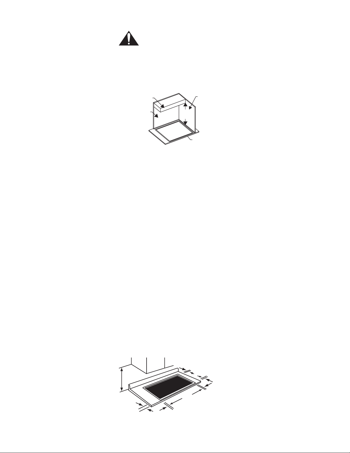
Figure 1 - Cabinet Requirements
Cabinet Bottom
(Unprotected)
Building Side
Wall
Building Back
Wall
30” min.
(762 mm)
Cooking
Surface
This unit is designed for installation in the counter top with zero clearance to
adjacent walls and projecting surfaces constructed of combustible materials. A 30inch (76.2 cm) minimum clearance is required between the top of the cooktop and
the bottom of an unprotected cabinet. A 24-inch (60.9 cm) minimum distance is
necessary when the bottom of the wood or metal cabinet is protected by not less
than 1/4 inch (6.35 mm) of a flame retardant material covered with not less than No.
28 MSG sheet steel, 0.015-inch (0.4 mm) thick stainless steel, 0.024-inch (0.6 mm)
aluminum, or 0.020-inch (0.5 mm) thick copper. Flame retardant materials bear the
mark:
UNDERWRITERS LABORATORIES INC.
CLASSIFIED
MINERAL AND FIBER BOARDS
SURFACE BURNING CHARACTERISTICS
Followed by the flame spread and smoke ratings, these designations are shown as
“FHC (Flame Spread)/(Smoke Developed).” Materials with “O” flame spread ratings
are flame retardant. Local codes may allow other flame spread ratings.
The minimum horizontal clearance from the sides and back edge of the cooktop to
the adjacent vertical combustible walls is 0 (zero) inches.
Countertop Requirements The cutout dimensions depend upon whether the installation is for replacement,
new construction, or installation in a solid surface countertop material, such as
Surel™, Corian® etc. These materials require larger cutouts, use of heat reflective
tape and rounded corners. Always consult the countertop manufacturer for specific
installation instructions.
Figure 2 - Countertop Requirements
1" (25.4 mm) Flat Area
1-1/4" (31.8 mm) Flat Area
30" (76.2 cm)
Minumum
2-1/2"
(63,8 mm)
Setback Distance
from front edge of counter-
(
top to front edge of cutout.)
1" (25.4 mm)
Flat Area
B
1" (25.4 mm) Flat Area
C
English 2
Page 5
Model # Minimum Inches / (mm) Maximum Inches / (mm)
CEM304 BC19-7/8" / (505 mm)
28-3/4" / (731 mm)
CEM365 BC19-7/8" / (505 mm)
34-3/4" / (883 mm)
CEM456 BC19-7/8" / (505 mm)
43-3/4" / (1111 mm)
*For solid surface countertop installations, use maximum cutout dimensions and consult surface manufacturer for
specific cutting instructions.
Power Requirements Power Supply is dual rated: 240 Volts or 208 Volts, 3 wire, 60 Hz, with the following
circuit breaker requirements:
• Model CEM304: 30 Amp circuit breaker
• Model CEM365: 40 Amp circuit breaker
• Model CEM456: 50 Amp circuit breaker
• All Models: 240 Volt, 3 Wire, 60 Hz / 208 Volt, 3 Wire, 60 Hz
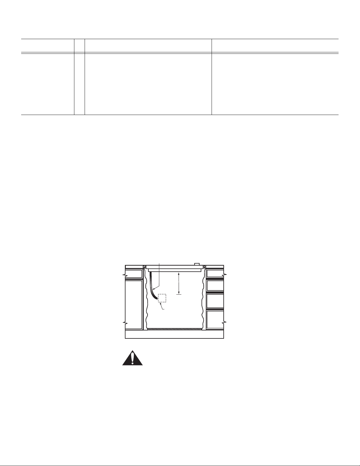
Install a junction box (not supplied), below the counter top within 3 feet (91.4 cm) of
flexible conduit (supplied) located at the right rear corner of the cooktop rough-in
box. Plan the installation of the unit so that the location of the junction box is within 3
feet (91.4 cm) of the right rear of the cooktop bottom. It must be accessible from the
front of the cabinet.
20" / (508 mm)
28-7/8" / (734 mm)
20" / (508 mm)
34-7/8" / (886 mm)
20" / (508 mm)
43-7/8" / (1114 mm)
Figure 3 - Junction Box Installation
Conduit
(approx 3 ft.(91.4 cm))
12”
(30.4 cm)
(approx)
“j” Box
Installation Procedure
Seal with Foam Tape A foam tape is provided to seal the cooktop edges to the countertop. Turn cooktop
upside down and apply tape approximately 1/16” (1.6 mm) from the glass edges.
Use tape around the entire glass perimeter. Cut off excess tape where tape ends
butt.
WARNING:
To avoid electrical shock hazard, before installing the cooktop, switch
power off at the service panel and lock the panel to prevent the power
from being switched on accidentally.
English 3
Page 6
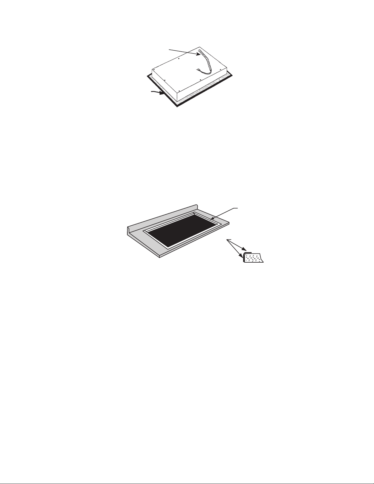
Figure 4 - Seal with Tape
Swivel Conduit Connector
Foam
Ta pe
Seal
Prepare the Countertop Cut out the countertop per the dimensions shown in section Countertop Cutout
Dimensions above. Always consult the countertop manufacturer for specific
instructions.
Countertops made from natural (i.e. granite and marble) or SOLID SURFACE
MATERIALS, such as Surell™ and Corian®, require special cutout preparation and
installation procedures. Follow the guidelines below for preparing the cutout for solid
surfaces.
Figure 5 - Prepare the Countertop
shows location of
aluminum reflective
tape
tape top and vertical
sides of cutout
1. Round the cutout corners according to instructions from the countertop manufacturer.
2. Apply heat reflective tape (such as 3M™/Scotch® Aluminum Foil Tape #425 or
#427) around the cutout so that it folds over the top and side surfaces. Be sure
the tape extends beyond the outermost flange of the cooktop. All corners should
also be covered with tape.
3. Attach brackets to the burner box using washers and screws provided. Use a wooden block underneath the countertop before tightening the bracket screws.
4. Center cooktop in the cutout to ensure adequate clearance between the burner
box and countertop edge. (A light pencil mark along the center of front edge and
side edge of cooktop and counter will aid in the positioning of the cooktop in the
center.)
5. Trim excess aluminum tape from along the frame edges. BE CAREFUL not to scratch the countertop.
Secure Cooktop to Countertop The cooktop should be secured to the countertop using the hold-down brackets
provided. Prior to inserting cooktop into cutout, turn cooktop upside down and attach
brackets to the burner box using the washers and screws.
English 4
Place cooktop into cutout. Insert clamping screws into the brackets and secure
cooktop to countertop.
Use a wood block to protect fragile countertop materials.
Page 7

Figure 6 - Secure Cooktop to Countertop
burner box
bracket
adjusting screw
Electrical Connection 1. Attach flexible conduit to the junction box.
2. Connect the cooktop lead wires to the junction box supply wires in proper
phase. For all models, connect black (L1) to black, red (L2) to red, green
wire to ground.
NOTE: If the cooktop is installed and connected as specified above, it will be completely
grounded in compliance with the National Electrical Code.
3. Remove everything from the cooktop surface and apply Cooktop Cleaning Creme (packaged with cooktop) as directed in Use and Care Manual.
4. Turn on power supply.
5. Test operation.
wood block
CAUTION:
Your cooktop surface needs to be cleaned daily. Refer to the Use and
Care section before using it for the first time.
Before Calling Service
Product Data Plate
If the elements do not heat or if the indicator “on” light does not glow, check the
power source to see if a fuse has blown or if the circuit breaker has tripped.
Refer to the Warranty in the Use and Care Manual. See Use and Care Manual for
troubleshooting information.
The data plate shows the model and serial number of your cooktop. It is located in
the center front area of the rough-in box, underneath the cooktop.
Keep your invoice or escrow papers for warranty validation if service is needed.
English 5
Page 8

Table des matières
Sécurité . . . . . . . . . . . . . . . . . . . . . . . . . . . . . . . . . . . . .1
INSTRUCTIONS DE SÉCURITÉ IMPORTANTES . . . . . . . . . . . . . . . . . . . . . . . 1
Installation . . . . . . . . . . . . . . . . . . . . . . . . . . . . . . . . . .2
Avant de commencer . . . . . . . . . . . . . . . . . . . . . . . . . . . . . . . . . . . . . . . . . . . . . 2
Outils et pièces nécessaires . . . . . . . . . . . . . . . . . . . . . . . . . . . . . . . . . . . . . . . . . . . . . . . . . . . . . . . . . . . . . . . . . . 2
Pièces comprises . . . . . . . . . . . . . . . . . . . . . . . . . . . . . . . . . . . . . . . . . . . . . . . . . . . . . . . . . . . . . . . . . . . . . . . . . . 2
Dimensions hors tout . . . . . . . . . . . . . . . . . . . . . . . . . . . . . . . . . . . . . . . . . . . . . . . . . . . . . . . . . . . . . . . . . . . . . . . . 2
Exigences pour l’armoire . . . . . . . . . . . . . . . . . . . . . . . . . . . . . . . . . . . . . . . . . . . . . . . . . . . . . . . . . . . . . . . . . . . . . 2
Exigences pour le plan de travail . . . . . . . . . . . . . . . . . . . . . . . . . . . . . . . . . . . . . . . . . . . . . . . . . . . . . . . . . . . . . . . 3
Exigences d’alimentation . . . . . . . . . . . . . . . . . . . . . . . . . . . . . . . . . . . . . . . . . . . . . . . . . . . . . . . . . . . . . . . . . . . . . 4
Marche à suivre d’installation . . . . . . . . . . . . . . . . . . . . . . . . . . . . . . . . . . . . . . . . . . . . . . . . . . 4
Apposer du ruban mousse . . . . . . . . . . . . . . . . . . . . . . . . . . . . . . . . . . . . . . . . . . . . . . . . . . . . . . . . . . . . . . . . . . . 4
Préparation du plan de travail . . . . . . . . . . . . . . . . . . . . . . . . . . . . . . . . . . . . . . . . . . . . . . . . . . . . . . . . . . . . . . . . . 4
Fixer la plaque de cuisson au plan de travail . . . . . . . . . . . . . . . . . . . . . . . . . . . . . . . . . . . . . . . . . . . . . . . . . . . . . 5
Connexions électriques . . . . . . . . . . . . . . . . . . . . . . . . . . . . . . . . . . . . . . . . . . . . . . . . . . . . . . . . . . . . . . . . . . . . . . 6
Avant d’effectuer un appel de service . . . . . . . . . . . . . . . . . . . . . . . . . . . . . . . . . . . . . . . . . . . . 6
Plaque signalétique . . . . . . . . . . . . . . . . . . . . . . . . . . . . . . . . . . . . . . . . . . . . . . . . . . . . . . . . . . 6
Cet appareil électroménager de Thermador est fait par
BSH Home Appliances Corporation
5551 McFadden Ave.
Huntington Beach, CA 92649
Questions ?
1-800-735-4328
www.thermador.com
Nous attendons de vos nouvelles !
Page 9

INSTRUCTIONS DE SÉCURITÉ IMPORTANTES
LIRE ET CONSERVER CES INSTRUCTIONS
INSTALLATEUR : LAISSER CES INSTRUCTIONS AVEC L’APPAREIL UNE FOIS L’INSTALLATION COMPLÉTÉE.
IMPORTANT : CONSERVER POUR L’INSPECTEUR LOCAL.
Instructions de sécurité importantes
AVERTISSEMENT :
Une installation, réglage, modification, service ou entretien inadéquats peuvent
causer des dommages à la propriété ou des blessures. Consulter le guide. Pour de
l’aide ou de l’information additionnelle, consulter un installateur qualifié, un centre
de service ou le fabricant.
• Demander à l’installateur d’indiquer l’emplacement du coupe-circuit ou du
fusible. Le noter à des fins de références.
• S’assurer que l’appareil est adéquatement installé et mis à la terre par un
technicien qualifié.
Exigences d’équipement et utilisation sécuritaire
• Avant de brancher le cordon électrique, s’assurer que tous les contrôles sont en
position arrêt (OFF).
• Pour éliminer le risque de brûlures ou d’incendie en passant au-dessus d’une
surface chaude, l’espace de rangement dans l’armoire au-dessus de l’appareil
devrait être évité. S’il y a un espace de rangement, le risque peut être réduit en
installant une hotte à projection horizontale ayant 5 po (12,7 cm) minimum du
bas de l’armoire.
• Cet appareil a été testé conformément à la norme ANSI/UL 858 pour la sécurité
des cuisinières électriques domestiques et CAN/CSA-22.2 No.61, norme
nationale pour cuisinières domestiques du Canada. Il incombe au propriétaire
et à l’installateur de déterminer si des exigences et des normes additionnelles
s’appliquent pour une installation spécifique.
Installation
Avant de commencer
Outils et pièces nécessaires 1. Tournevis à lame Phillips
2. Perceuse avec mèche 1/4 po (6,35 mm)
3. Ruban à mesurer
Pièces comprises 1. Ruban mousse
2. Fixations (4)
3. Vis, n° 10-32 x 2 ½ po (63,8 mm) (4)
4. Vis à métal, n°8 x 3/8 po (9,5 mm) (4)
5. Rondelles (4)
Si des pièces sont manquantes ou endommagées, téléphoner au numéro ou écrire
à l’adresse indiqués à la fin du guide.
Dimensions hors tout Ces dimensions sont hors tout.
• Modèle CEM304 : largeur 30 po (76,2 cm)
• Modèle CEM265 : largeur 36 po (91,4 cm)
• Modèle CEM456 : largeur 45 po (549,4 mm)
• Tous les modèles : profondeur 21 5/8 po (549,4 cm)
• Hauteur au-dessus du plan de travail : ¼ po (6,35 mm)
Français 1
Page 10

Exigences pour l’armoire
A
ATTENTION :
Pour éliminer le risque de brûlures ou d’incendie en passant au-dessus
d’une surface chaude, l’espace de rangement dans l’armoire au-dessus
de l’appareil devrait être évité. S’il y a un espace de rangement, le risque
peut être réduit en installant une hotte à projection horizontale ayant 5 po
(12,7 cm) minimum du bas de l’armoire.
Figure 1 – Exigences pour l’armoire
rmoire inférieure
(non protégée)
Mur arrière
de l’édifice
30 po min.
(762 mm)
Cet appareil est conçu pour une installation dans un plan de travail avec
dégagement zéro aux murs adjacents et surfaces protégées fabriqués de matériaux
combustibles. Un dégagement minimum de 30 po (76,2 cm) est requis entre le haut
de la plaque de cuisson et le bas de l’armoire non protégée. Une distance minimale
de 24 po (60,9 cm) est nécessaire lorsque le bas d’une armoire en bois ou en métal
est protégée par un matériau résistant à la chaleur de pas moins de 1/4 po (6,35
mm) avec pas moins de n°. 28 MSG feuille de métal, acier inoxydable d’épaisseur
de 0.015 po (
po (
0,5 mm). Les matériaux résistant à la chaleur portent la mention:
0,4 mm), aluminium 0.024 po (0,6 mm), ou cuivre d’épaisseur de 0.020
Mur latéral
de l’édifice
Surface
de cuisson
LABORATOIRES DES ASSUREURS, U.L.
CLASSIFIÉS
MINÉRAUX ET PANNEAUX DE FIBRES
CARACTÉRISTIQUES DE SURFACES INFLAMMABLES
Suivie des cotes de propagation de flamme et de fumée, ces désignations figurent
comme FHC (propagation de flamme/formation de fumée). Les matériaux avec la
cote « 0 » de propagation de flamme sont ignifuges. Les codes locaux peuvent
permettre d’autres cotes de propagation de flamme.
Le dégagement horizontal minimum depuis les côtés et le bord arrière de la plaque
de cuisson aux murs combustibles verticaux adjacents est de 0 po (0 cm).
Exigences pour le plan de travail Les dimensions de découpe dépendent de si l’installation est pour un
remplacement, une nouvelle construction ou une installation dans un matériau
solide de plan de travail comme Surel™, Corian®, etc. Ces matériaux requièrent
des découpes plus larges, l’utilisation de ruban réfléchissant la chaleur et de coins
ronds. Toujours consulter le fabricant du plan de travail concernant les instructions
d’installation spécifiques.
Figure 2 – Exigences du plan de travail
30 po
(76,2 cm) min.
zone plate 1 po (25,4 mm)
B
zone plate 1-1/4 po
(31,8 mm)
zone plate
C
distance de
retrait 2 1/2 po
(63,8 mm) depuis le bord
avant de la plaque de cuisson
au bord de la découpe)
zone plate 1 po
(25,4 mm)
1 po (25,4 mm)
Français 2
Page 11

Modèle
N
°
Minimum
po / (mm)
Maximum
po / (mm)
CEM304 BC19 7/8 po / (505 mm)
28 3/4 po / (731 mm)
CEM365 BC19 7/8 po/ (505 mm)
34 3/4 po / (883 mm)
CEM456 BC19-7/8 po / (505 mm)
43-3/4 po / (1111 mm)
*Pour les installation de plan de travail en surface solide, utiliser les dimensions de découpe maximales et
consulter le fabricant de surface pour les instructions de découpe spécifiques.
Exigences d’alimentation Alimentation à cote jumelée : 240 ou 208 volts, 3 fils, 60 Hz, avec exigences de
coupe-circuit suivantes :
• Modèle CEM304 : coupe-circuit de 30 Amp
• Modèle CEM365: coupe-circuit de 40 Amp
• Modèle CEM465: coupe-circuit de 50 Amp
• Tous les modèle : 240 volts, 3 fils, 60 Hz / 208 volts, 3 fils, 60 Hz
Installer une boîte de jonction (non comprise) sous le plan de travail à moins de 3 pi
(91,4 cm) du conduit flexible (fourni) situé au coin arrière gauche de la boîte brute
de la plaque de cuisson. Planifier l’installation de l’appareil afin que l’emplacement
de la boîte de jonction soit à moins de 3 pi (91,4 cm) de l’arrière droite du bas de la
plaque de cuisson. Elle doit être accessible depuis le devant de l’armoire.
20 po / (508 mm)
287/8 po / (734 mm)
20 po / (508 mm)
34 7/8 po / (886 mm)
20 po / (508 mm)
43-7/8 po / (1114 mm)
Figure 3 – Installation de boîte de jonction
Conduit (environ
3 pi (91,4 cm)
environ
12 po
(30,4 cm)
boîte de
jonction
Marche à suivre d’installation
Apposer du ruban mousse Un ruban mousse est fourni pour sceller les bords de la plaque de cuisson au plan
de travail. Mettre la plaque de cuisson à l’envers et apposer le ruban à environ 1/16
po (1.6 mm) des bords en verre. Mettre le ruban tout autour du paramètre du verre.
Couper l’excédant du ruban.
AVERTISSEMENT :
Pour éviter tout risque de choc électrique, avant d’installer la plaque de
cuisson, mettre l’alimentation hors circuit au panneau de service et le
verrouiller pour éviter toute mise en circuit accidentelle.
Français 3
Page 12

Figure 4 – sceller la plaque de cuisson
connecteur du
conduit pivotant
joint du
ruban
mousse
Préparation du plan de travail Découper le plan de travail selon les dimensions données au tableau 1,
dimensions de découpe du plan de travail. Toujours consulter le fabricant du
plan de travail pour les instructions spécifiques.
Les plans de travail fabriqués de MATÉRIAUX naturels (ex.: granite, marbre) ou
SURFACE SOLIDE comme Surell™ et Corian®, requièrent une préparation de
découpe et des marches à suivre d’installation spéciales. Suivre les directives cidessous pour la préparation de la découpe de surface solide.
Figure 5 – préparation du plan du travail
Indique l'emplacement du
ruban aluminium
réfléchissant
Fixer la plaque de cuisson au plan de travail
Mettre le ruban sur le
haut et les côtés verticaux
de la découpe
1. Arrondir les coins de la découpe selon les instructions du fabricant du plan de travail.
2. Apposer du ruban réfléchissant la chaleur (comme ruban aluminium
3M™/Scotch® n° 425 ou 427) autour de la découpe afin qu’il se replie par
dessus le haut et les surfaces latérales. S’assurer que le ruban dépasse le
rebord extrême de la plaque de cuisson. Tous les coins doivent être couverts de
ruban.
3. Attacher les fixations sur la boîte de brûleur à l’aide des rondelles et des vis fournies. Utiliser une cale en bois sous le plan de travail avant de serrer les vis de fixations.
4. Centrer la plaque de cuisson dans la découpe pour assurer un dégagement
adéquat entre la boîte de brûleur et le bord du plan de travail. (Une légère
marque au crayon le long du centre du bord avant et le bord latéral de la plaque
de cuisson et du comptoir permettra de positionner la plaque de cuisson au
centre.)
5. Enlever l’excédant de ruban aluminium le long des bords du cadre. FAIRE ATTENTION à ne pas égratigner le plan de travail.
La plaque de cuisson doit être fixée de façon sécuritaire au plan de travail à l’aide
des fixations fournies. Avant d’insérer l’appareil dans la découpe, mettre l’appareil à
l’envers et installer les fixations sur la boîte de brûleur avec les rondelles et les vis.
Français 4
Placer la plaque de cuisson dans la découpe. Insérer les vis pinces dans les
fixations et fixer la plaque de cuisson au plan de travail.
Utiliser une cale en bois pour protéger le matériau fragile du plan de travail.
Page 13

Figure 6 – Fixer la plaque de cuisson au plan de travail
Boîte de
brûleur
Fixation
Vis de réglage
Connexions électriques 1. Fixer le conduit flexible à la boîte de jonction.
2. Brancher les fils de la plaque de cuisson sur les fils d’alimentation de la boîte de
jonction comme suit. Pour tous les modèles, brancher noir (L1) sur noir,
rouge (L2) sur rouge, vert sur mise à la terre.
REMARQUE : Si la plaque de cuisson est installée et branchée tel qu’il est indiqué ci-dessus, elle
sera mise à la terre conformément au Code national d’électricité.
3. Enlever tout matériel de la surface de la plaque de cuisson et appliquer la crème fournie avec l’appareil tel qu’il est indiqué dans le guide d’utilisation et d’entretien.
4. Mettre l’alimentation en circuit.
5. Vérifier le fonctionnement.
Cale en bois
Avant d’effectuer un appel de service
Plaque signalétique
ATTENTION :
La plaque de cuisson doit être nettoyée quotidiennement. Consulter le
guide d’utilisation et d’entretien avant d’utiliser la première fois.
Si les éléments ne chauffent pas ou si le voyant marche ne s’allume pas, vérifier la
source d’alimentation ; le fusible est peut-être grillé ou le coupe-circuit est
déclenché.
Consulter la garantie dans le guide d’utilisation et d’entretien et le guide de
dépannage.
La plaque signalétique donne les numéros de modèle et de série de la plaque de
cuisson. Elle est située sur le centre avant de la boîte brute, sous la plaque de
cuisson.
Conserver la facture et les documents pertinents pour la validation de la garantie si
un service est requis.
Français 5
Page 14

Contenidos
Seguridad . . . . . . . . . . . . . . . . . . . . . . . . . . . . . . . . . . . . . . . . . . . . . . . . . . . . . . 1
INSTRUCCIONES IMPORTANTES DE SEGURIDAD . . . . . . . . . . . . . . . . . . . . 1
Instalación . . . . . . . . . . . . . . . . . . . . . . . . . . . . . . . . . .2
Antes de comenzar . . . . . . . . . . . . . . . . . . . . . . . . . . . . . . . . . . . . . . . . . . . . . . . 2
Herramientas y partes necesarias . . . . . . . . . . . . . . . . . . . . . . . . . . . . . . . . . . . . . . . . . . . . . . . . . . . . . . . . . . . . . . 2
Partes incluidas . . . . . . . . . . . . . . . . . . . . . . . . . . . . . . . . . . . . . . . . . . . . . . . . . . . . . . . . . . . . . . . . . . . . . . . . . . . . 2
Dimensiones generales . . . . . . . . . . . . . . . . . . . . . . . . . . . . . . . . . . . . . . . . . . . . . . . . . . . . . . . . . . . . . . . . . . . . . . 2
Requerimientos para los gabinetes . . . . . . . . . . . . . . . . . . . . . . . . . . . . . . . . . . . . . . . . . . . . . . . . . . . . . . . . . . . . . 2
Requerimientos para la cubierta . . . . . . . . . . . . . . . . . . . . . . . . . . . . . . . . . . . . . . . . . . . . . . . . . . . . . . . . . . . . . . . 3
Requerimientos eléctricos . . . . . . . . . . . . . . . . . . . . . . . . . . . . . . . . . . . . . . . . . . . . . . . . . . . . . . . . . . . . . . . . . . . . 4
Procedimiento de Instalación . . . . . . . . . . . . . . . . . . . . . . . . . . . . . . . . . . . . . . . . . . . . . . . . . . . 4
Sellar con cinta de espuma . . . . . . . . . . . . . . . . . . . . . . . . . . . . . . . . . . . . . . . . . . . . . . . . . . . . . . . . . . . . . . . . . . . 4
Preparar la cubierta . . . . . . . . . . . . . . . . . . . . . . . . . . . . . . . . . . . . . . . . . . . . . . . . . . . . . . . . . . . . . . . . . . . . . . . . . 4
Fijar la parrilla a la cubierta . . . . . . . . . . . . . . . . . . . . . . . . . . . . . . . . . . . . . . . . . . . . . . . . . . . . . . . . . . . . . . . . . . . 5
Conexión eléctrica . . . . . . . . . . . . . . . . . . . . . . . . . . . . . . . . . . . . . . . . . . . . . . . . . . . . . . . . . . . . . . . . . . . . . . . . . . 6
Antes de solicitar servicio . . . . . . . . . . . . . . . . . . . . . . . . . . . . . . . . . . . . . . . . . . . . . . . . . . . . . 6
Placa con información del producto . . . . . . . . . . . . . . . . . . . . . . . . . . . . . . . . . . . . . . . . . . . . . . 6
Este electrodomestico de Thermador es hecho por
BSH Home Appliances Corporation
5551 McFadden Ave.
Huntington Beach, CA 92649
¿Preguntas?
1-800-735-4328
www.thermador.com
¡Esparamos oir de usted!
Page 15

INSTRUCCIONES IMPORTANTES DE SEGURIDAD
LEA Y GUARDE ESTAS INSTRUCCIONES
INSTALADOR: DEJE ESTAS INSTRUCCIONES CON EL APARATO CUANDO TERMINE LA INSTALACIÓN.
IMPORTANTE: GUARDE ESTAS INSTRUCCIONES PARA EL INSPECTOR LOCAL.
Instrucciones Importantes de Seguridad
ADVERTENCIA:
La instalación, ajuste, alteración, servicio o mantenimiento no apropiado puede
causar lesiones o dañar la propiedad. Consulte este manual. Consulte a un
instalador calificado, una agencia de servicio o al fabricante para recibir ayuda o
información adicional.
• Pídale al instalador que le muestre el lugar del cortacircuitos o fusible.
Márquelo para encontrarlo fácilmente.
• Asegúrese que su aparato está instalado y puesto a tierra correctamente por un
técnico calificado.
Requerimientos de seguridad del equipo y su uso
• Antes de enchufar un cable eléctrico, asegúrese que todos los controles están
en la posición OFF (Apagado).
• Para eliminar el riesgo de quemaduras o fuego al inclinarse encima de
superficies calientes, se deben evitar espacios de almacenamiento en los
gabinetes arriba de las unidades superficiales. Si se debe proporcionar espacio
para gabinetes, se puede reducir el riesgo al instalar una campana que salga
horizontalmente un mínimo de 5 pulgadas (12.7 cm) más allá del fondo del
gabinete.
• Este aparato ha sido probado de acuerdo con la norma de seguridad ANSI/UL
858 para estufas eléctricas domésticas y la norma nacional de Canadá CAN/
CSA-22.2 No.61 para estufas de uso doméstico. Es la responsabilidad del
propietario y del instalador determinar si aplican requerimientos y normas
adicionales en instalaciones específicas.
Instalación
Antes de comenzar
Herramientas y partes necesarias 1. Destornillador de cabeza Phillips (de cruz)
2. Taladro con broca de 1/4” (6.35 mm)
3. Cinta de medir
Partes incluidas 1. Cinta de espuma
2. Abrazaderas de retención (4)
3. Tornillos, #10-32 x 2 1/2” (63.8 mm) (4)
4. Tornillos autorroscantes, #8 x 3/8” (9.5 mm) (4)
5. Arandelas (4)
Si falta alguna parte o si está dañada, llame al teléfono o escriba a la dirección
listada dentro de la contraportada.
Dimensiones generales Estas dimensiones son generales.
• Modelo CEM73: Ancho de 30" (76.2 cm)
• Modelo CEM93: Ancho de 36" (91.4 cm)
• Modelo CEM93: Ancho de 45” (114.3 cm)
• Todos los modelos: Profundidad 21-5/8" (549.4 mm)
• Altura arriba de la cubierta: 1/4" (6.35 mm)
Español 1
Page 16

Requerimientos para los gabinetes
PRECAUCIÓN:
Para eliminar el riesgo de quemaduras o fuego al inclinarese encima de
superficies calientes, se deben evitar espacios de almacenamiento en los
gabinetes arriba de las unidades superficiales. Si se debe proporcionar
espacio para gabinetes, se puede reducir el riesgo al instalar una
campana que salga horizontalmente un mínimo de 5 pulgadas (12.7 cm)
más allá del fondo de los gabinetes.
Figura 1 - Requerimientos para los gabinetes
Fondo del gabinete
(No protegido)
Pared lateral
del edificio
Pared trasera
del edificio
30” min.
(762 mm)
Superficie
de cocinar
Esta unidad está diseñada para una instalación en la cubierta con cero espacio
libre a las paredes adyacentes y las superficies salientes que son hechas de
materiales combustibles. Se requiere un mínimo espacio libre de 30 pulgadas (76.2
cm) entre la parte superior de la parrilla y el fondo de un gabinete no protegido. Se
requiere una mínima distancia de 24 pulgadas (60.9 cm) cuando el fondo del
gabinete de madera o de metal está protegido por un material retardante al fuego
cubierto con no menos de 1/4 de pulgada (6.35 mm) de espesor de lámina No. 28
MSG, 0.015-pulg. (0.4 mm) de acero inoxidable, 0.024-pulg. (0.6 mm) de aluminio,
o 0.020-pulg. (0.5 mm) de cobre. Los materiales retardantes al fiuego llevan la
leyenda:
UNDERWRITERS LABORATORIES INC.
CLASIFICADO
PLACAS DE MINERALES Y DE FIBRA
CARACTERÍSTICAS DE COMBUSTIÓN DE SUPERFICIES
Seguido por las clasificaciones de propagación de llamas y humo, estas
designaciones aparecen como “FHC (propagación de llamas)/(humo desarrollado).”
Materiales con clasificaciones “O” de propagación de llamas son considerados
como retardantes al fuego. Los códigos locales pueden permitir otras
clasificaciones de la propagación de llamas.
El mínimo espacio horizontal libre de los costados y del borde trasero de la parrilla
a las paredes verticales adyacentes que son combustibles es 0 pulgadas.
Requerimientos para la cubierta Las dimensiones del recorte dependen si la instalación es para reemplazo, una
construcción nueva o una instalación en una cubierta con un material sólido como
Surel™, Corian® etc. Estos materiales requieren de recortes más grandes, del uso
de cinta termorreflectante y de esquinas redondas. Siempre consulte al fabricante
de la cubierta para recibir instrucciones específicas de instalación.
Español 2
Page 17

Figura 2 - Requerimientos para la cubierta
30" Mínimo
(76.2 cm)
2-1/2"
(63,8 mm) Distancia
del borde delantero de la cubierta
(
al borde delantero del recorte.)
Modelo #
Pulgadas / (mm)
CEM304 BC19-7/8" / (505 mm)
28-3/4" / (731 mm)
CEM365 BC19-7/8" / (505 mm)
34-3/4" / (883 mm)
CEM456 BC19-7/8" / (505 mm)
43-3/4" / (1111 mm)
Mínimo
C
1" (25.4 mm)
Área plana
1" (25.4 mm) Área plana
1-1/4" (31.8 mm) Área plana
B
1" (25.4 mm)
Área plana
20" / (508 mm)
28-7/8" / (734 mm)
20" / (508 mm)
34-7/8" / (886 mm)
20" / (508 mm)
43-7/8" / (1114 mm)
Máximo
Pulgadas / (mm)
*Para instalaciones en cubiertas con superficies sólidas, use las máximas dimensiones de recorte y consulte al
fabricante de la superficie para recibir instrucciones específicas sobre el recorte.
Requerimientos eléctricos La fuente de alimentación sirve para dos voltajes: 240 Volts o 208 Volts, 3 hilos, 60
Hz, con los siguientes requerimientos para el cortacircuitos:
• Modelo CEM304: Cortacircuitos de 30 amperes
• Modelo CEM365: Cortacircuitos de 40 amperes
• Modelo CEM465: Cortacircuitos de 50 amperes
• Todos los modelos: 240 Volts, 3 hilos, 60 Hz / 208 Volts, 3 hilos, 60 Hz
Instale una caja de conexiones (no se incluye) abajo de la cubierta dentro de 3 pies
(91.4 cm) del conducto flexible (incluido) que se encuentra en la esquina trasera
derecha de la caja empotrada de la parrilla. Planee la instalación de la unidad de
modo que se pueda localizar la caja de conexiones dentro de 3 pies (91.4 cm) de la
parte trasera izquierda del fondo de la parrilla. Se debe tener acceso desde el frente
del gabinete.
Figura 3 - instalación de la caja de conexiones
Conducto
aprox. 3 pies (91.4 cm)
12”
(30.4 cm)
aprox.
Caja de
conexiones
Español 3
Page 18

Procedimiento de Instalación
ADVERTENCIA:
Para evitar una descarga eléctrica antes de instalar la parrilla, apague la
corriente en el panel de servicio y bloquee este panel para evitar que se
prenda accidentalmente.
Sellar con cinta de espuma Se incluye una cinta de espuma para sellar los bordes de la parrilla a la cubierta.
Voltee la parrilla y aplique la cinta aproximadamente a una distancia de 1/16” (1.6
mm) de los bordes de cristal. Use la cinta alrededor de todo el perímetro de cristal.
Corte el exceso de cinta donde se topan los extremos de la cinta.
Figura 4 - Sellar la parrilla
Conector flexible
del conducto
Sello con
cinta de
espuma
Preparar la cubierta Haga sus recortes en la cubierta según las dimensiones indicadas en la Tabla 1
Dimensiones del recorte en la superficie de la cubierta. Siempre consulte al
fabricante de la cubierta para instrucciones específicas.
Cubiertas hechas de materiales naturales (i.e. granito y mármol) o SUPERFICIES
DE MATERIALES SÓLIDOS, como Surell™ y Corian®, requieren procedimientos
especiales de la preparación e instalación del recorte. Siga los lineamientos abajo
para preparar el recorte para superficies sólidas.
Figura 5 - Preparar la cubierta
muestra la posición
de la cinta reflectante
de aluminio
encintar la parte superior
y los costados del recorte
1. Redondee las esquinas del recorte de acuerdo a las instrucciones del fabricante de la cubierta.
2. Aplique cinta termorreflectante (como cinta de aluminio 3M™/Scotch® #425 o
#427) alrededor del recorte de modo que se doble encima de la parte superior y
de los costados. Asegúrese de extender la cinta más allá del borde exterior de
la parrilla. Se deben tapar todas las esquinas con cinta.
3. Fije las abrazaderas a la caja de los quemadores utilizando las arandelas y los tornillos que se incluyen. Utilice un bloque de madera debajo de la cubierta antes de apretar los tornillos de las abrazaderas.
4. Centre la parrilla en el recorte para asegurar un espacio libre adecuado entre
la caja de quemadores y el borde de la cubierta. (Una ligera marca con un lápiz
a lo largo del centro del borde delantero y del borde lateral de la parrilla y de la
cubierta ayuda en el posicionamiento de la parrilla en el centro.)
5. Corte el exceso de la cinta de aluminio a lo largo de los bordes del marco. TENGA CUIDADO de no rayar la cubierta.
Español 4
Page 19

Fijar la parrilla a la cubierta Se debe fijar la parrilla a la cubierta por medio de las abrazaderas de sujeción que
se incluyen. Antes de insertar la parrilla en el recorte, voltee la parrilla y fije las
abrazaderas a la caja de quemadores utilizando las arandelas y los tornillos.
Coloque la parrilla en el recorte. Inserte los tornillos de apriete en las abrazaderas y
fije la parrilla a la cubierta.
Use un bloque de madera para proteger materiales frágiles de la cubierta.
Figura 6 - Fijar la parilla a la cubierta
caja del
quemador
abrazadera
tornillo de ajuste
Conexión eléctrica 1. Conecte el conducto flexible a la caja de conexiones.
2. Conecte los hilos conductores de la parrilla a los cables de alimentación de la
caja de conexiones en la fase apropiada. Para todos los modelos, conecte
negro (L1) a negro, rojo (L2) a rojo y el cable verde a tierra.
bloque de madera
NOTA: Si se instala y se conecta la parrilla tal como se especifica arriba, quedará
Antes de solicitar servicio
Placa con información del producto
completamente aterrizada de acuerdo con el código eléctrico nacional.
3. Quite todas las cosas de la superficie de la parrilla y aplique la crema de limpieza para parrilla (incluida con la parrilla) según las indicaciones en el manual de uso y cuidado.
4. Prenda la fuente de alimentación.
5. Compruebe la operación.
CUIDADO:
La superficie de su parrilla debe ser limpiada cada día. Consulte el
manual de uso y cuidado para información sobre cómo resolver
problemas.
Si los elementos no calientan o si no se prende la luz indicadora de “encendido”,
revise la fuente de alimentación para ver si se quemó un fusible o si se activó el
cortacircuitos.
Consulte la garantía en el manual de uso y cuidado. Vea el manual de uso y
cuidado para información sobre cómo resolver problemas.
La placa con información indica el número de modelo y el número de serie de su
parrilla. Se encuentra en el área delantera central de la caja empotrada, debajo de
la parrilla.
Guarde su factura o sus papeles para validar la garantía si se necesita servicio.
Español 5
Page 20

5551 McFadden Avenue, Huntington Beach, CA 92649 • 800-735-4328 • www.thermador.com
9000080974 • 5V0AH1 • Rev. B • 04/07 © BSH Home Appliances Corporation, 2005 • All rights reserved
Litho in USA
 Loading...