

Page 1

Rugged Enterprise Server 200
Installation Guide
Version 2.1 — September 2001
Themis Computer—Americas and Pacific Rim
3185 Laurelview Court
Fremont, CA 94538
Phone (510) 252-0870
Fax (510) 490-5529
World Wide Web http://www.themis.com
Themis Computer—Rest of World
1, Rue Des Essarts
Z.A. De Mayencin
38610 Gieres, France
Phone 33 76 59 60 61
Fax 33 76 63 00 30
Page 2
Copyright © 2001 Themis Computer, Inc.
ALL RIGHTS RESERVED. No part of this publication may be reproduced in any form, by
photocopy, microfilm, retrieval system, or by any other means now known or hereafter invented without
the prior written permission of Themis Computer.
The information in this publication has been carefully checked and is believed to be accurate. However,
Themis Computer assumes no responsibility for inaccuracies. Themis Computer retains the right to
make changes to this publication at any time without prior notice. Themis Computer does not assume
any liability arising from the application or use of this publication or the product(s) described herein.
RESTRICTED RIGHTS LEGEND: Use, duplication, or disclosure by the United States Government
is subject to the restrictions set forth in DFARS 252.227-7013 (c)(1)(ii) and FAR 52.227-19.
TRADEMARKS
THEMIS™ is a registered trademark of Themis Computer, Inc.
SOLARIS™ is a registered trademark of Sun Microsystems
SPARC™ is a registered trademark of SPARC International
All other trademarks used in this publication are the property of their respective owners.
Themis Customer Support
North America, South America, and Pacific Rim
Telephone: 510-252-0870
Fax: 510-490-5529
E-mail: [email protected]
Web Site: http://www.themis.com
Rugged Enterprise Server 200 Installation Guide
September 2001
Part Number:110041-021
Page 3

Version Revision History
Version 2.1 ..................................................................................September 2001
• Added recommended procedure for removing Server Assembly (Chapter 2, p. 2-4).
• Revised procedure for installing CPU Modules (Chapter 2, p. 2-12).
• Assorted minor revisions.
Version 2.0 ............................................................................................. July 2001
• Described new rear I/O panel (Chapter 1).
• Modified text and figures describing new rear AC panel and power supplies (Chapters 2 and 4).
• Added Chapter 5, “Alarm Monitoring”.
• Assorted minor revisions.
Version 1.0 ................................................................................... December 2000
Themis Computer
iii
Page 4

Rugged Enterprise Server 200 Installation Guide
iv
Themis Computer
Page 5

Table of Contents
Preface .................................................................................................................................. xix
1. Product Overview ......................................................................................................... 1-1
1.1 Basic Design .......................................................................................................... 1-2
1.1.1 System I/O Panel ....................................................................................... 1-4
1.1.1.1 Custom VME P2 I/O Interface Panel ......................................... 1-7
1.1.2 Memory System ......................................................................................... 1-7
1.1.2.1 Memory Interleaving .................................................................. 1-8
1.1.2.2 Memory System Timing ........................................................... 1-11
2. Major Assembly Installation ........................................................................................ 2-1
2.1 Server Subsystem Assembly .................................................................................. 2-1
2.1.1 Powering Off the System ........................................................................... 2-2
2.1.2 Removing the Server Assembly ................................................................ 2-4
2.1.3 Jumper-Pin Configurations ....................................................................... 2-8
2.1.3.1 Serial-Port Configuration ............................................................ 2-8
2.1.3.2 Flash-PROM Configuration ........................................................ 2-9
2.1.4 CPU Module ............................................................................................ 2-10
2.1.4.1 Installing and Removing a CPU Module .................................. 2-10
2.1.5 PCI Card .................................................................................................. 2-14
2.1.5.1 Installing a PCI Card ................................................................. 2-14
2.1.5.2 Removing a PCI Card ............................................................... 2-15
2.1.6 UPA Graphics Card ................................................................................. 2-16
2.1.6.1 Installing a Graphics Card ........................................................ 2-16
2.1.6.2 Removing a Graphics Card ....................................................... 2-17
2.1.6.3 Elite3D UPA Graphics Card .................................................... 2-17
2.1.6.4 Elite3D UPA Graphics Card Patch Information ....................... 2-19
Themis Computer
2.1.7 DIMM ...................................................................................................... 2-20
2.1.7.1 Removing the Memory Riser Assembly ................................... 2-20
2.1.7.2 Removing a DIMM ................................................................... 2-24
2.1.7.3 Replacing a DIMM ................................................................... 2-25
v
Page 6

Rugged Enterprise Server 200 Installation Guide
2.1.7.4 Replacing the Memory Riser Assembly ................................... 2-27
2.1.8 Audio Module Assembly ......................................................................... 2-29
2.1.8.1 Removing the Audio Module Assembly .................................. 2-29
2.1.8.2 Replacing the Audio Module Assembly ................................... 2-30
2.1.9 NVRAM/TOD Assembly ........................................................................ 2-31
2.1.9.1 Removing the NVRAM/TOD Assembly .................................. 2-31
2.1.9.2 Replacing the NVRAM/TOD Assembly .................................. 2-32
2.1.10 DC-to-DC Converter Assembly .............................................................. 2-33
2.1.10.1 Removing the DC-to-DC Converter Assembly ........................ 2-33
2.1.10.2 Replacing the DC-To-DC Converter Assembly ....................... 2-34
2.2 VME I/O Boards .................................................................................................. 2-35
2.2.1 Removing a VME Board ......................................................................... 2-36
2.2.2 Replacing a VME Board .......................................................................... 2-36
2.3 Hard-Disk Drives ................................................................................................. 2-37
2.3.1 Removing a Hard-Disk Drive .................................................................. 2-37
2.3.2 Replacing a Hard-Disk Drive .................................................................. 2-37
2.4 CD-ROM Drive ................................................................................................... 2-39
2.4.1 Removing a CD-ROM Drive ................................................................... 2-39
2.4.2 Replacing a CD-ROM Drive ................................................................... 2-39
2.5 Power Supplies .................................................................................................... 2-41
2.5.1 Removing a Power Supply ...................................................................... 2-41
2.5.2 Replacing a Power Supply ....................................................................... 2-41
2.6 Server Assembly Fans ......................................................................................... 2-43
2.6.1 Removing the Server Fans ....................................................................... 2-44
2.6.2 Replacing the Server Fans ....................................................................... 2-45
2.6.3 Removing and Replacing the Server Fan Filter ....................................... 2-46
2.7 VME I/O Fan Tray ............................................................................................... 2-47
3. Configuring Your System ............................................................................................. 3-1
3.1 Introduction ............................................................................................................ 3-1
3.2 Server Configuration .............................................................................................. 3-2
3.2.1 RES-204 Server Checklist ......................................................................... 3-2
3.3 VME I/O Configuration ......................................................................................... 3-2
3.3.1 RES-204 VME I/O Checklist .................................................................... 3-2
vi
Themis Computer
Page 7

Table of Contents
4. Managing Your System ................................................................................................ 4-1
4.1 Sun Management Software .................................................................................... 4-1
4.2 Themis Management Applications ........................................................................ 4-2
4.2.1 Power Supply Status LEDs ........................................................................ 4-2
4.2.2 VME DC Power Voltage Monitoring ........................................................ 4-4
4.2.3 Cooling System Monitoring and Control ................................................... 4-4
4.2.3.1 Server Subsystem Fans ............................................................... 4-4
4.2.3.2 VME I/O Subsystem Fans .......................................................... 4-5
4.2.3.3 Power Supply Fan ....................................................................... 4-7
4.2.4 System Air Flow Monitoring ..................................................................... 4-7
4.3 Status/Alarm Monitoring and Control ................................................................... 4-8
4.3.1 Front-Panel Status LEDs ........................................................................... 4-9
4.3.2 VME Buffer/Alarm Jumper-Pin Configurations ..................................... 4-10
4.4 VME-Bridge Card Jumper-Pin Configurations ................................................... 4-12
5. Alarm Monitoring ......................................................................................................... 5-1
5.1 Monitoring Power Supplies ................................................................................... 5-2
5.2 Monitoring Cooling Devices ................................................................................. 5-2
5.3 Monitoring the VME IO Subsystem ...................................................................... 5-2
5.3.1 Air Flow ..................................................................................................... 5-2
5.3.2 Temperature Sensors .................................................................................. 5-2
5.3.3 VME Backplane DC Voltage .................................................................... 5-3
5.3.4 User Interface I/O ...................................................................................... 5-3
5.3.4.1 Input Signals ............................................................................... 5-3
5.3.4.2 Output Signals ............................................................................. 5-3
5.3.4.3 Connectors .................................................................................. 5-4
5.4 VME Buffer/Alarm Card Registers ....................................................................... 5-5
5.4.1 LED Control/Status Register: Address Offset 0x00 ................................. 5-6
5.4.2 Air Flow Status Register: Address Offset 0x04 ........................................ 5-6
5.4.3 User Input Status Register: Address Offset 0x08 ..................................... 5-7
5.4.4 Relay Control Register: Address Offset 0x0c ........................................... 5-7
5.4.5 PS1 / PS2 / PS3 Status Register:
Address Offset 0x10 / 0x14 / 0x18 ............................................................ 5-8
5.4.6 DC Control/Status Register: Address Offset 0x1c ................................... 5-8
Themis Computer
vii
Page 8

Rugged Enterprise Server 200 Installation Guide
5.4.7 Thermal Sensor Control/Status Registers:
Address Offset 0x20, 0x24, 0x28 ............................................................ 5-10
5.4.8 VME Fans Control/Status Register:
Address Offset 0x2c ................................................................................. 5-11
5.4.9 Revision/ID Register: Address Offset 0x30 ........................................... 5-12
5.4.10 Interrupt Enable Register: Address Offset 0x34 ..................................... 5-13
5.4.11 Interrupt Status Register: Address Offset 0x38 ...................................... 5-14
5.5 VME Bridge Card Registers ................................................................................ 5-16
5.5.1 Server Temperature Sensor Auxiliary Register
(Address 1ff.f172.0000) ........................................................................... 5-16
5.5.2 Server Warning Temperature Flag Register
(Address 1ff.f170.0000) ........................................................................... 5-16
5.5.3 VME Buffer/Alarm Card Interrupt Control Register
(Address 1ff.f170.4000) ........................................................................... 5-17
5.5.4 Server Shutdown Temperature Flag Register
(Address 1ff.f170.2000) ........................................................................... 5-17
5.5.5 Server Air Flow Interrupt Register
(Address 1ff.f170.6000) ........................................................................... 5-17
5.5.6 Server Fan Status Register
(Address 1ff.f100.0000) ........................................................................... 5-18
5.6 Address map ........................................................................................................ 5-19
5.6.1 Alarm Monitoring User Interface ............................................................ 5-20
5.7 Specific OBP variables ........................................................................................ 5-23
5.8 Register Address Map Summary ......................................................................... 5-24
Appendix A. Regulatory and Safety Compliance Statements ...................................... A-1
A.1 FCC and DOC Class Notices ................................................................................ A-2
A.1.1 FCC Class A Notice .................................................................................. A-2
A.1.2 DOC Class A Notice - Avis DOC, Classe A ............................................ A-2
A.2 VCCI Statement .................................................................................................... A-3
A.3 Declaration of Conformity .................................................................................... A-4
A.4 Regulatory Compliance Statements ...................................................................... A-5
A.5 Agency Compliance .............................................................................................. A-7
viii
A.6 German Acoustic Compliance .............................................................................. A-7
A.7 Safety Agency Compliance Statement ................................................................. A-8
Themis Computer
Page 9

Table of Contents
Appendix B. Rugged Enterprise Server 200Model Specifications ...............................B-1
B.1 Model RES-204 .....................................................................................................B-1
B.1.1 Physical Specifications .............................................................................B-1
B.1.2 Electrical Specifications ............................................................................B-2
B.1.3 Environmental Requirements ....................................................................B-3
Appendix C. Connector Signal and Pinout Assignments ..............................................C-1
C.1 Power Connectors ..................................................................................................C-2
C.2 Serial Ports COM1 and COM2 ............................................................................C-11
C.3 UltraSCSI Connector ...........................................................................................C-12
C.4 Parallel Port Connector ........................................................................................C-16
C.5 Keyboard/Mouse Connector ................................................................................C-17
C.6 Twisted-Pair Ethernet Connector .........................................................................C-18
C.6.1 TPE Cable-Type Connectivity .................................................................C-18
C.6.2 External UTP-5 Cable Lengths ................................................................C-19
C.7 Audio Connectors ................................................................................................C-19
C.8 UPA Graphics Card Connectors ..........................................................................C-20
C.8.1 Expert3D Graphics Card ..........................................................................C-21
C.8.1.1 Video Output Port .....................................................................C-21
C.8.1.2 Stereo Output Port ....................................................................C-22
C.8.1.3 External Video Synchronization Port .......................................C-23
C.8.2 Creator3D Graphics Card ........................................................................C-23
C.8.3 Elite3D Graphics Card .............................................................................C-23
Index ........................................................................................................................I-1
Themis Computer
ix
Page 10

Rugged Enterprise Server 200 Installation Guide
x
Themis Computer
Page 11

Table of Contents
List of Figures
Figure 1-1 The RES-204 (Front View).............................................................................. 1-1
Figure 1-2 RES-204 Functional Flow Diagram ................................................................ 1-2
Figure 1-3 RES-204 Components (Front View)................................................................ 1-3
Figure 1-4 RES-204 Components (Rear View)................................................................. 1-4
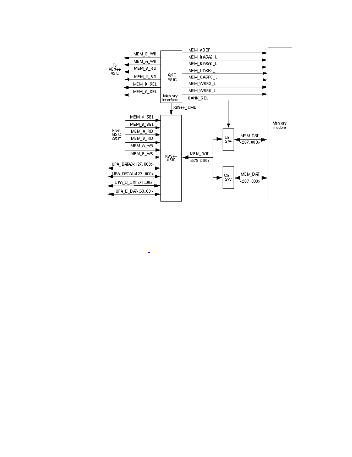
Figure 1-5 Memory System Functional Block Diagram ................................................... 1-8
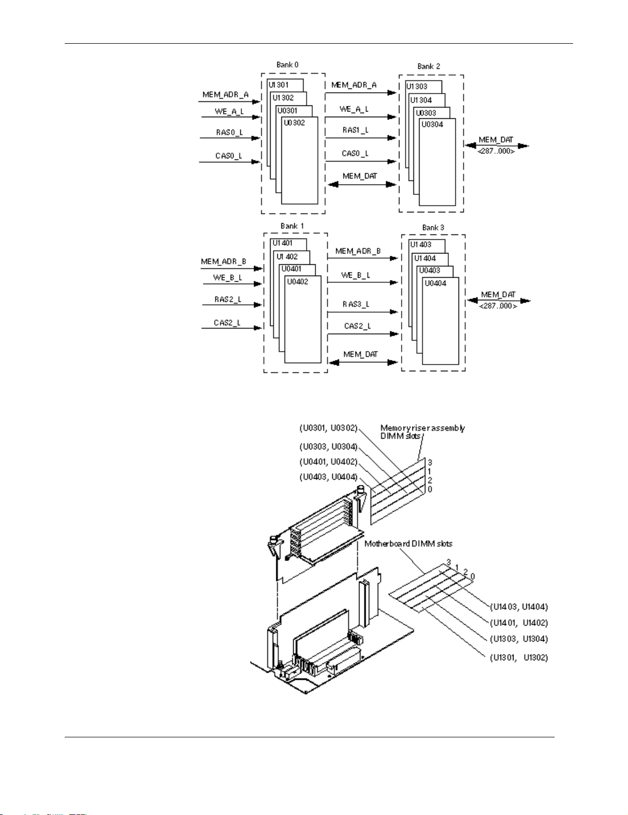
Figure 1-6 Memory Module Functional Block Diagram................................................... 1-9
Figure 1-7 DIMM Mapping............................................................................................... 1-9
Figure 2-1 The RES-204 Server Subsystem Assembly..................................................... 2-2
Figure 2-2 The Ultra 80 Motherboard ............................................................................... 2-3
Figure 2-3 Turn the RES-204 Key-Switch to the OFF Position........................................ 2-4
Figure 2-4 Remove the Disk-Tray Dust Cover and Loosen Assembly Bolts ................... 2-5
Figure 2-5 Remove the Server Subsystem Assembly ....................................................... 2-6
Figure 2-6 Left- (A) and Right-Hand Views of Removed Server Assembly.................... 2-6
Figure 2-7 Remove the Server Assembly Protective Cover Plate..................................... 2-7
Figure 2-8 Location of the Motherboard Serial-Port Jumpers .......................................... 2-8
Figure 2-9 Location of the Motherboard Flash-PROM Jumpers ...................................... 2-9
Figure 2-10 Remove Screws holding the CPU Module Cover Plate ................................ 2-10
Figure 2-12 Locate the CPU Module Slot ......................................................................... 2-11
Figure 2-11 CPU Module Cover Plate Removed .............................................................. 2-11
Figure 2-13 Locate and Remove the CPU Module ........................................................... 2-12
Figure 2-14 Installing or Removing a CPU Module ......................................................... 2-13
Figure 2-15 Placement of the PCI Card............................................................................. 2-14
Figure 2-16 Placement of the Graphics Card .................................................................... 2-16
Figure 2-17 Placement of the Elite3D Card ...................................................................... 2-19
Figure 2-18 Removing the Memory Riser Assembly........................................................ 2-21
Figure 2-19 Remove the Riser Assembly from the Motherboard ..................................... 2-22
Themis Computer
xi
Page 12

Rugged Enterprise Server 200 Installation Guide
Figure 2-20 Remove the 8 Screws from the Riser Support Plate (A and B),
then remove DIMM(s) from the Riser Assembly or
Motherboard Surface (C)............................................................................... 2-23
Figure 2-21 Removing and Replacing a DIMM................................................................ 2-24
Figure 2-22 Allocation of DIMMs according to Bank ...................................................... 2-25
Figure 2-23 Setting the Memory Riser Assembly Thumbscrew Torque........................... 2-28
Figure 2-24 Removing and Replacing the Audio Module Assembly ............................... 2-29
Figure 2-25 Locate and Remove the NVRAM/TOD carrier............................................. 2-31
Figure 2-26 Locate and Remove the DC-to-DC Converter............................................... 2-33
Figure 2-27 The VME I/O Subsystem............................................................................... 2-35
Figure 2-28 Replacing the RES-204 Hard-Disk Drives .................................................... 2-38
Figure 2-29 Location of the RES-204 CD-ROM Drive .................................................... 2-40
Figure 2-30 Location of the RES-204 Server Fans ........................................................... 2-43
Figure 2-31 Remove Each Server Fan, Starting with Fan 3.............................................. 2-45
Figure 2-32 Remove the Server Fan Filter by Pulling Evenly at Both Corners................ 2-46
Figure 2-33 Replace the Server Fan Filter by Inserting Evenly into the Slot ................... 2-47
Figure 2-34 The VME I/O Fan Tray ................................................................................. 2-48
Figure 4-1 RES-204 Power Supply Status LEDs .............................................................. 4-2
Figure 4-2 The RES-204 Cooling System......................................................................... 4-5
Figure 4-3 Air is Pulled through Vents at the Front of the Cabinet .................................. 4-6
Figure 4-4 Hot Air is Exhausted from the RES-204 through Rear Vents ......................... 4-6
Figure 4-5 Data Flow through the VME Buffer/Alarm Card within the RES-204 ........... 4-8
Figure 4-6 RES-204 Front-Panel LEDs and VME Reset Switch (SYSR) ...................... 4-10
Figure 4-7 Location of Jumper-Pins on the VME Buffer/Alarm Board.......................... 4-10
Figure 4-8 Location of Jumper Pins on the VME-Bridge PCI Card ............................... 4-12
Figure C-1 Ultra 80 Motherboard Connectors ................................................................... C-3
Figure C-2 DC-to-DC Converter Connector J4105 ........................................................... C-4
Figure C-3 Power Supply Connector J4106....................................................................... C-5
xii
Themis Computer
Page 13

Table of Contents
Figure C-4 Power Supply Connector J4107....................................................................... C-6
Figure C-5 DC-to-DC Converter Connector J4108 ........................................................... C-7
Figure C-6 PCI Fan Connector J4109 ................................................................................ C-8
Figure C-7 CPU Fan Connector J4110 .............................................................................. C-8
Figure C-8 Combined Cable Assembly Connector J4111 ................................................. C-9
Figure C-9 Peripheral Power Cable Assembly Connector J4112 .................................... C-10
Figure C-10 Serial Ports COM 1 and COM2 Connector Pin Configuration ..................... C-11
Figure C-11 UltraSCSI Connector Pin Configuration ....................................................... C-13
Figure C-12 Parallel Port Connector Pin Configuration .................................................... C-16
Figure C-13 Keyboard/Mouse Connector Pin Configuration ............................................ C-17
Figure C-14 TPE Connector Pin Configuration................................................................. C-18
Figure C-15 Audio Connector Configuration (I/O Panel is Opposite Order) ................... C-19
Figure C-16 Parallel Port Connector Pin Configuration .................................................... C-20
Figure C-17 Expert3D Connector Panel ............................................................................ C-21
Figure C-18 Expert3D 7-Pin DIN Female Stereo Connector ............................................ C-22
Themis Computer
xiii
Page 14

Rugged Enterprise Server 200 Installation Guide
xiv
Themis Computer
Page 15

Table of Contents
List of Tables
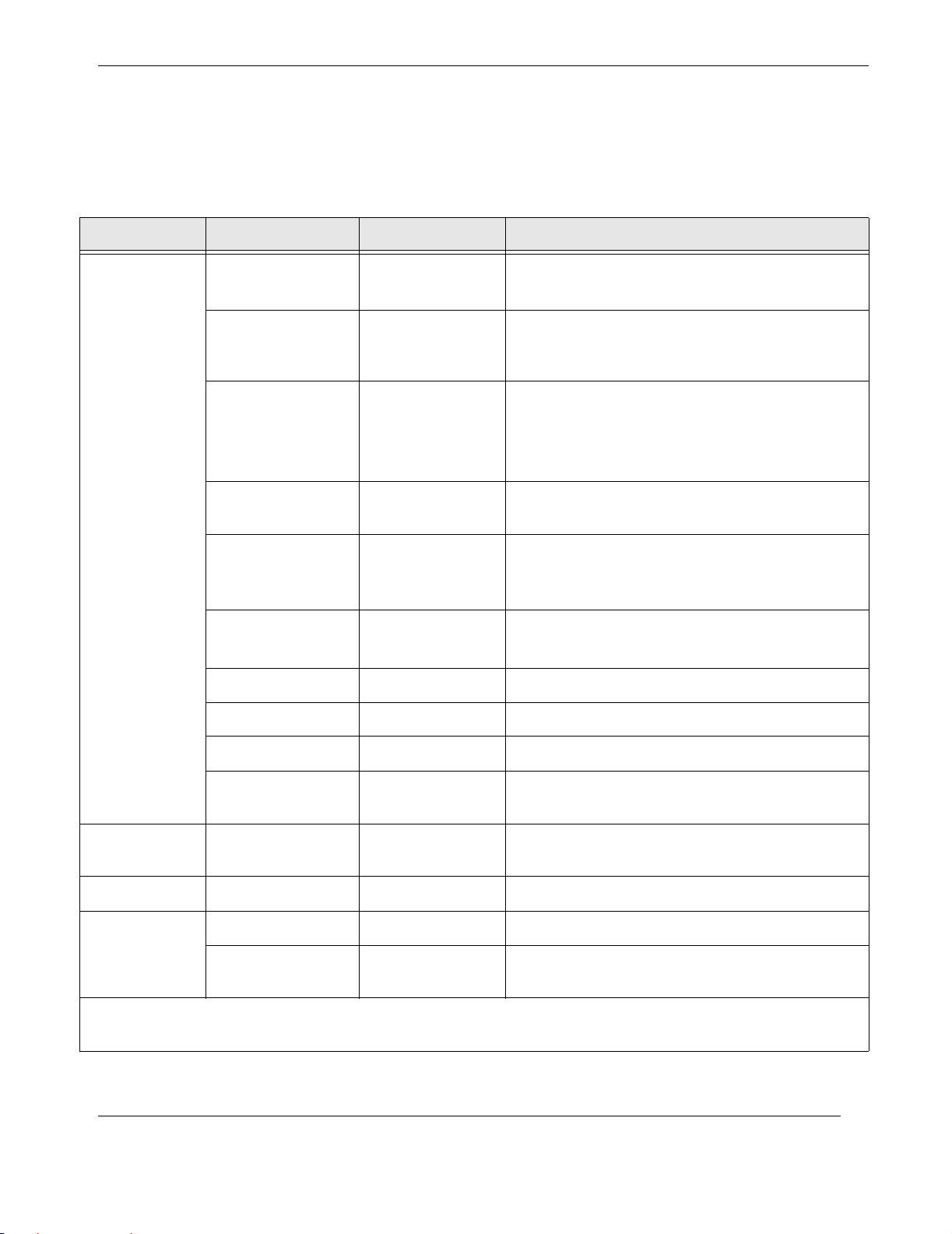
Table 1-1 Major Components of the RES-204................................................................. 1-5
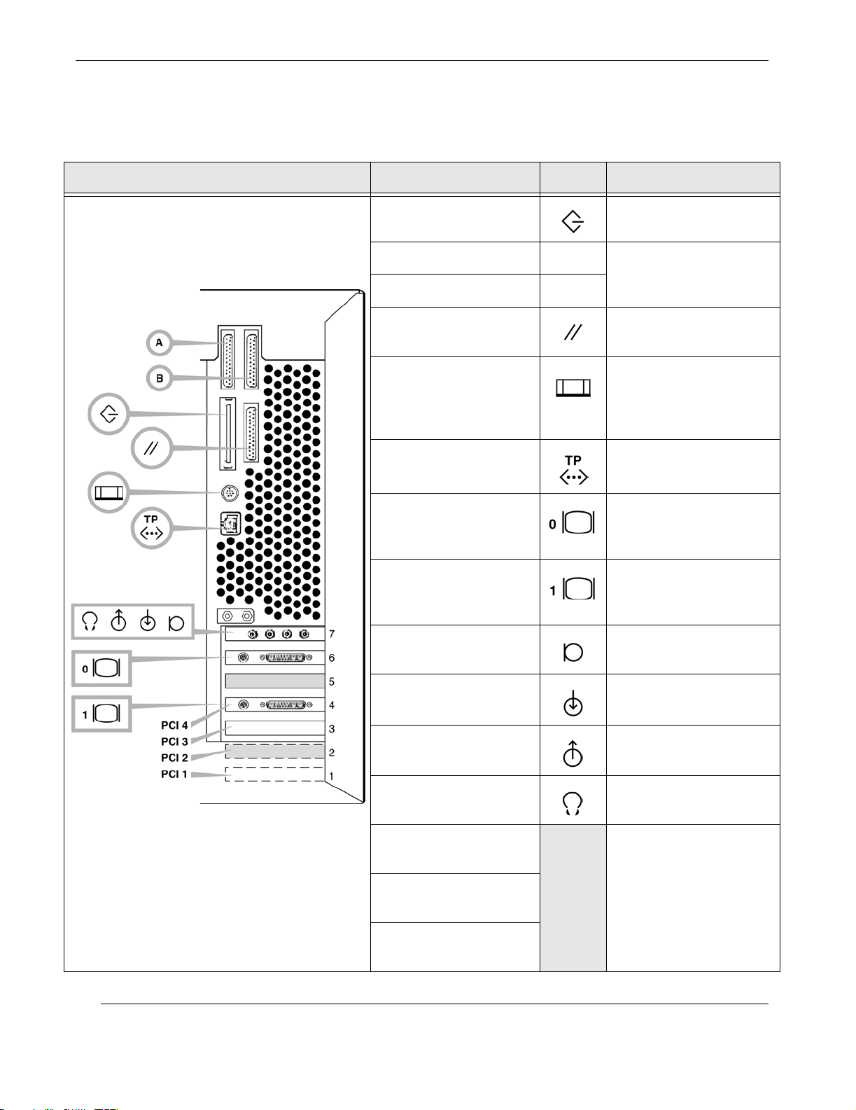
Table 1-2 I/O Panel Connection IDs and Definitions ...................................................... 1-6
Table 1-3 1-Gbyte DIMM Configuration Scenario........................................................ 1-10
Table 1-4 Memory Relative Starting Address with No Interleaving ............................. 1-10
Table 1-5 Memory Addressing for 2-Way Interleaving................................................. 1-11
Table 1-6 Memory Addressing for 4-Way Interleaving................................................. 1-11
Table 2-1 Serial-Port Jumper Settings ............................................................................. 2-8
Table 2-2 Flash-PROM Jumper Settings ......................................................................... 2-9
Table 2-3 Order of CPU Module Installation................................................................. 2-12
Table 2-4 DIMM Allocation on the RES-204................................................................ 2-26
Table 3-1 RES-204 Server Configuration........................................................................ 3-3
Table 3-2 RES-204 VME-I/O Configuration—Arbitration/Address Mapping ............... 3-5
Table 3-3 RES-204 VME-I/O Configuration—Master and Slave Access Modes........... 3-7
Table 4-1 Power Key-Switch LED Interpretation............................................................ 4-3
Table 4-2 VME Subsystem Front-Panel LED and Switch Interpretation........................ 4-9
Table 4-3 VME Buffer/Alarm Jumper-Pin Configurations ........................................... 4-11
Table 4-4 VME-Bridge PCI Card Jumper-Pin Configurations...................................... 4-13
Table 5-5 Led control register (read mode) ..................................................................... 5-6
Table 5-6 Air flow sensor register (read mode) ............................................................... 5-6
Table 5-7 User input status register (read mode) ............................................................. 5-7
Table 5-8 User relay control register (read mode) ........................................................... 5-7
Table 5-9 Power Supply status register (read mode) ....................................................... 5-8
Table 5-10 DC voltage source control/status register (read mode).................................... 5-8
Tab le 5- 11 Thermal sensor control/status register (read mode)....................................... 5-10
Table 5-12 VME fan control/status register (read mode) ................................................ 5-11
Table 5-13 DC voltage source status register (read mode) .............................................. 5-12
Themis Computer
xv
Page 16

Rugged Enterprise Server 200 Installation Guide
Table 5-14 Interrupt Enable Register (Read Mode)......................................................... 5-13
Table 5-15 Interrupt status register (read mode).............................................................. 5-14
Table 5-16 Server temperature auxiliary register (read/write mode)............................... 5-16
Table 5-17 Server temperature warning register (read/write mode) ................................ 5-16
Table 5-18 VME Buffer/Alarm Card interrupt control register (read/write mode) ......... 5-17
Table 5-19 Server temperature shutdown register (read/write mode).............................. 5-17
Table 5-20 Server temperature shutdown register (read/write mode).............................. 5-17
Table 5-21 Server fan status register (read/write mode) .................................................. 5-18
Table 5-22 RES-204 Monitoring Register Address Summary......................................... 5-24
Tab le B-1 RES-204 Physical Specifications..................................................................... B-1
Tab le B-2 RES-204 Clearance and Service Access.......................................................... B-2
Tab le B-3 RES-204 Shipping Specifications.................................................................... B-2
Tab le B-4 RES-204 Electrical Specifications................................................................... B-2
Tab le B-5 RES-204 Temperature, Humidity, and Altitude Limits................................... B-3
Tab le C-1 Power Connectors ............................................................................................ C-2
Tab le C-2 DC-to-DC Converter Connector J4105 Pin Description ................................. C-4
Tab le C-3 Power Supply Connector J4106 Pin Description............................................. C-5
Tab le C-4 Power Supply Connector J4107 Pin Description............................................. C-6
Tab le C-5 DC-to-DC Converter Connector J4108 Pin Description ................................. C-7
Tab le C-6 PCI Fan Connector J4109 Pin Description ...................................................... C-8
Tab le C-7 CPU Fan Connector J4110 Pin Description .................................................... C-8
Tab le C-8 Combined Cable Assembly Connector J4111 Pin Description ....................... C-9
Tab le C-9 Peripheral Power Cable Assembly Connector J4112 Pin Description .......... C-10
Tab le C-1 0 Serial Port A and B Connector Pin Assignments .......................................... C-11
Tab le C-11 UltraSCSI Connector Pin Assignments ......................................................... C-13
Tab le C-1 2 Parallel Port Connector Pin Assignments ...................................................... C-16
Tab le C-1 3 Keyboard/Mouse Connector Pin Assignments .............................................. C-17
Tab le C-1 4 TPE Connector Pin Assignments................................................................... C-18
xvi
Themis Computer
Page 17

Table of Contents
Tab le C-1 5 CPU Fan Connector J4110 Pin Description .................................................. C-19
Tab le C-1 6 Audio Connector Line Assignment ............................................................... C-19
Tab le C-1 7 Parallel Port Connector Pin Assignments ...................................................... C-20
Tab le C-1 8 Expert3D Video Output Port ......................................................................... C-21
Tab le C-1 9 Expert3D Stereo Output Port ......................................................................... C-22
Themis Computer
xvii
Page 18

Rugged Enterprise Server 200 Installation Guide
xviii
Themis Computer
Page 19

Preface
This document, entitled Rugged Enterprise Server 200 Installation Guide, Version
1.0, provides instructions on how to install, configure, power up, boot, and perform
diagnostics on Model RES-204 of the Rugged Enterprise Server 200 family of Sun
Microsystems UltraSPARC-II-based servers. These instructions are intended for an
experienced system administrator with a knowledge of both networking and highspeed server systems.
Note: Whenever this manual refers to the Rugged Enterprise Server 200, the de-
scription describes properties and configurations common to all models of the
family. In the case of Version 1.0 of this manual, all descriptions apply to only
one model—the RES-204.
General Overview
Themis Computer
Model RES-204 is based on the Sun Microsystems Ultra 80TM workstation Motherboard, combined with a high-speed VME I/O subsystem that communicates with the
PCI bus of the Ultra 80 through a specially designed VME interface. To withstand
the extreme shock (over 15Gs), temperature conditions (over 50°C), and EMI associated with such demanding markets as military/aerospace and telecommunications,
Themis engineers have added custom hardware (protective plates, high-dissipation
heat sinks, ultra-high-air cooling, and component strengtheners, for example) to all
Sun CPU/Memory boards and PCI/Graphics I/O boards. With its fast computer
power, diverse I/O, and unyielding ruggedness, the RES-204 joins the larger Rugged
Enterprise Server 2000 family as one of the first Sun-based servers designed from
the ground up to withstand military and aerospace environmental requirements.
xix
Page 20
Rugged Enterprise Server 200 Installation Guide
V
V
V
V
Major Features
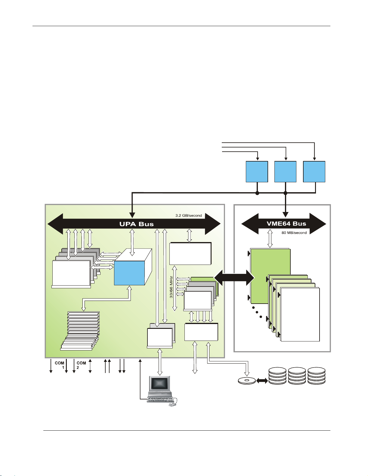
The major features of the RES-204 are incorporated into its ability to perform faster
processing and greater I/O throughput, and withstand harsh environments through
added ruggedness. The RES-204 consists of two major sections: the Server Sub-
system containing the Ultra 80 Motherboard and all of its CPU Modules, DIMMs,
and I/O boards, and the VME I/O Subsystem (see Figure below). There are a total
of 16 I/O slots, divided between six slots in the Server Subsystem and ten slots in the
VME Subsystem.
85 to 265 VAC
47 to 440 Hz
Ultra 80 Motherboard
UltraSPARC-II
CPU Module
450 MHz
4-MB Cache
s
t
o
l
s
4
DIMM
Modules
Memory
s
t
o
l
s
2
x
8
System
Control
Up to 4 GB
112 .5
MHz
UPA
Graphics
UPA-to-PCI
Interface Chip
PCI Bus
s
t
o
l
s
2
(U2P)
ME Bridge Card
PCI I/O
Boards
Ultrawide
SCSI
ME Interface
s
t
o
l
s
4
Power
Supply
Supply
1
ME I/O Subsystem
ME
Buffer/Alarm
Board
1
0
s
l
o
t
s
Power
2
VME64
cPCI
I/O Expansion
Board
Power
Supply
3
or
Dual-Channel
Parallel
Port
Serial
Ports
Ethernet
Port
AudioInAudio
Out
Keyboard
/ Mouse
xx
Ultrawide
SCSI
Port
CD-ROM Hard-Disk Drives (3)
32X
18 GB each
Themis Computer
Page 21

Preface
General Overview
Server Subsystem
The Server Subsystem consists primarily of the Ultra 80 Motherboard, which supports up to four 450-MHz UltraSPARC-II CPUs, with up to 4 GigaBytes of DIMM
modules, 4 MegaBytes of L2 cache, and 8 MB of Ecache, all contributing to faster
processing speeds. Of the six I/O slots on the Motherboard, two reside on the Ultra
80 UPA bus at 112.5 MHz, and four on the PCI bus at 33 or 66 MHz. A high-speed
interface chip serves to connect the PCI bus with the 3.2 GB/sec UPA bus.
The two UPA-based I/O slots are ideal for high-speed graphics boards such as the
Creator3D or Elite3D. Of the four PCI slots, at least one must contain a PCI I/O
board required to interface with the VME I/O Subsystem.
VME I/O Subsystem
The VME I/O Subsystem can be configured to support either ten single slots or two
separate units of 5 slots each, all slots accommodating either 6U VME boards or,
optionally, 6U cPCI boards. To connect with the PCI bus of the Server Motherboard,
VME slot 1 must be reserved for a customized VME Buffer/Alarm Board that serves
not only as a bridge to the Ultra 80 UPA bus through the PCI bus, but as an alarm
monitoring system to help manage RES-204 operations and functions.(see for more
detail).
Added Ruggedness
Themis redesigned the server system to provide a suitable platform for demanding
federal and aerospace markets—including expanded I/O capability, improved temperature handling, and extreme mechanical ruggedness—all contained in an open,
modular system. In addition, the RES-204 contains a high-capacity multiple-fan system that extends operational temperature range to over 50°C.
The RES-204 chassis can withstand up to 15Gs of shock. All mechanical structures
have natural vibration modes exceeding 28 Hz. Additionally, all critical electronic
components are designed to sustain high shock loads, while heat sinks have been
redesigned to minimize unsupported mass and moment of inertia.
Themis Computer
xxi
Page 22
Rugged Enterprise Server 200 Installation Guide
UNIX Commands
This document may not contain information on basic UNIX® commands and procedures such as shutting down the system, booting the system, and configuring
devices.
See one or more of the following for this information:
• Solaris Handbook for Sun Peripherals, which contains SolarisTM 2.x software
commands
• AnswerBookTM on-line documentation for the Solaris software environment
• Other software documentation that you received with your system
Shell Prompts
Shell Prompt
C shell machine_name%
C shell superuser machine_name#
Bourne shell and Korn shell $
Bourne shell and Korn shell superuser #
Website Information
Themis Computer corporate and product information may be accessed on the World
Wide Web by browsing the website http://www.themis.com.
xxii
Themis Computer
Page 23
Preface
Notes, Cautions, Warnings, and Sidebars
Notes, Cautions, Warnings, and Sidebars
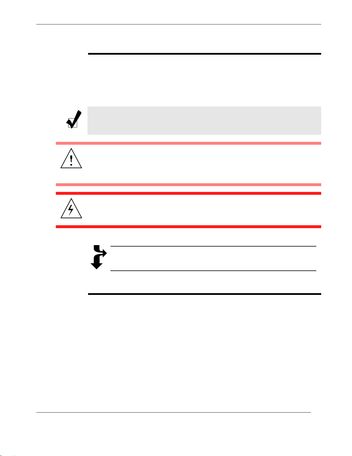
The following icons and formatted text are included in this document for the reasons
described:
Note: A note provides additional information concerning the procedure or action
being described that may be helpful in carrying out the procedure or action.
Caution: A caution describes a procedure or action that may result in injury to the
operator or equipment damage. This may involve—but is not restricted to—heavy
equipment or sharp objects. To reduce the risk, follow the instructions accompanying this symbol.
Warnin g : A warning describes a procedure or action that may cause injury to the
operator or equipment as a result of hazardous voltages. To reduce the risk of electrical shock and danger, follow the instructions accompanying this symbol.
Sidebar: A “sidebar” adds detail to the section within which it is placed,
but is not absolutely vital to the description or procedure of the section.
Your Comments are Welcome
We are interested in improving our documentation and welcome your comments and
suggestions. You can email your comments to us at [email protected].
Please include the document part number in the subject line of your email.
Themis Computer
xxiii
Page 24

Rugged Enterprise Server 200 Installation Guide
xxiv
Themis Computer
Page 25
Overview
1
Section
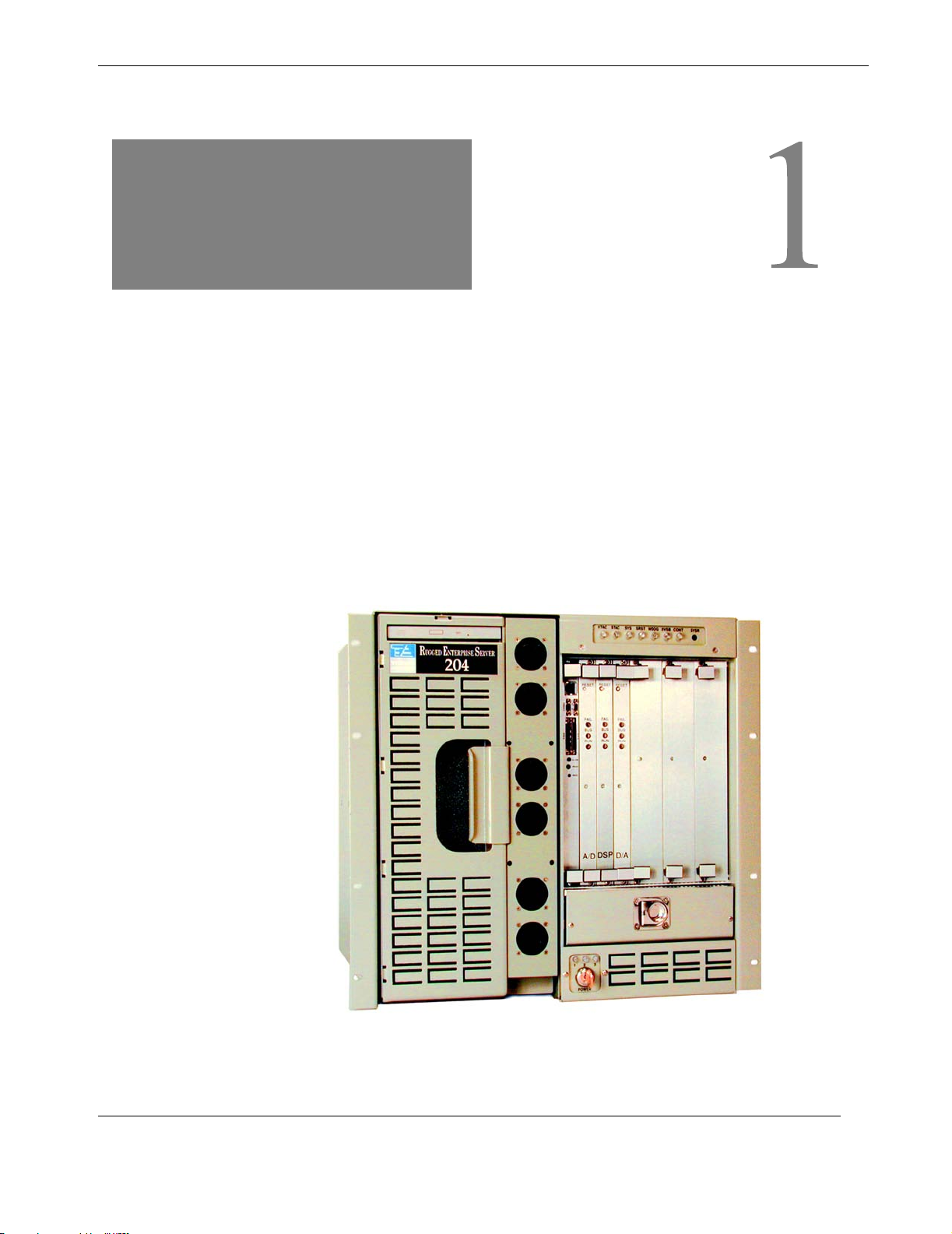
This document described how to install Model RES-204 (see Figure 1-1) of the
Rugged Enterprise Server 200 family of UltraSPARC-II-based servers. Designed for
high survivability under extreme environmental shock and temperature conditions,
the RES-204 is based on the Sun Microsystems Ultra 80TM workstation Motherboard.
It is ideal for both military/aerospace and telecommunications markets that demand
high computer power with diverse I/O capability.
Chapter
Product Overview
Themis Computer
Figure 1-1. The RES-204 (Front View)
1-1
Page 26
Rugged Enterprise Server 200 Installation Guide
V
V
V
V
1.1 Basic Design
Designed to fit a 19-inch RETMA rack on fully rotating, retractable slides, RES-204
measures 16.875” wide (excluding rack flange) by 17.5” high (10U) by 18.5” deep.
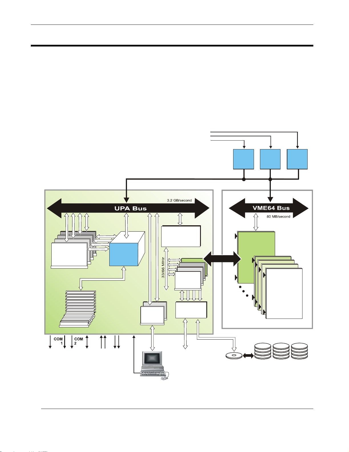
It consists of the following two main functional components (see Figure 1-2):
• Server Subsystem based on the Ultra 80 quad-processor Motherboard
• VME I/O Subsystem with 10 slots to accommodate 6U-high VME cards
85 to 265 VAC
47 to 440 Hz
Ultra 80 Motherboard
UltraSPARC-II
CPU Module
450 MHz
4-MB Cache
s
t
o
l
s
4
DIMM
Modules
Up to 4 GB
Memory
s
t
o
l
s
2
x
8
System
Control
112 .5
MHz
UPA
Graphics
UPA-to-PCI
Interface Chip
PCI Bus
s
t
o
l
s
2
(U2P)
ME Bridge Card
PCI I/O
Boards
Ultrawide
SCSI
ME Interface
s
t
o
l
s
4
Power
Supply
1
ME I/O Subsystem
ME
Buffer/Alarm
Board
1
0
s
l
o
t
s
Power
Supply
2
VME64
I/O Expansion
Board
Power
Supply
3
or
cPCI
Dual-Channel
Parall el
Port
Serial
Ports
Ethernet
Port
AudioInAudio
Out
Keyboard
/ Mouse
Figure 1-2.
RES-204 Functional Flow Diagram
1-2
Ultrawide
SCSI
Port
CD-ROM Hard-Disk Drives (3)
32X
18 GB each
Themis Computer
Page 27
1—Product Overview
Basic Design
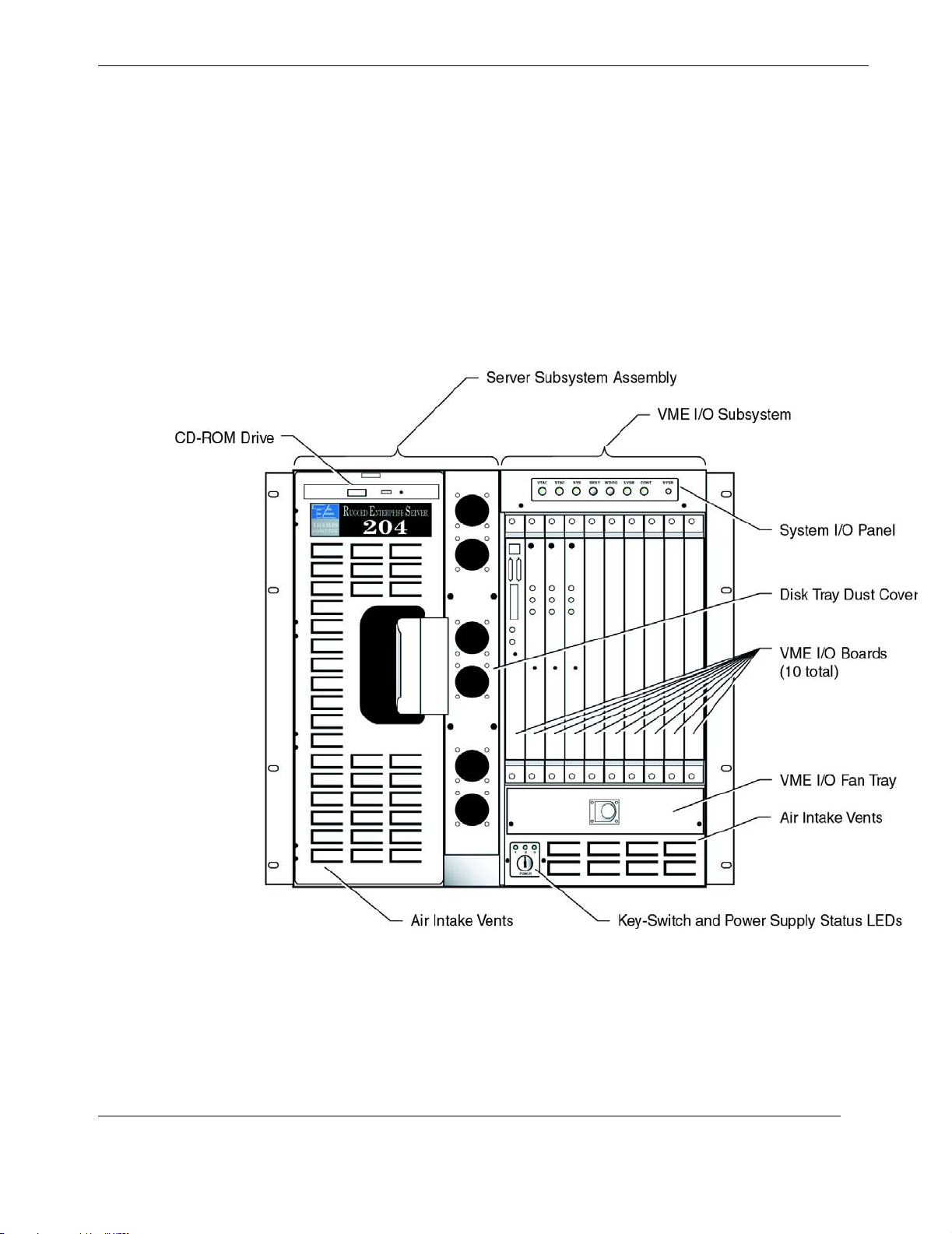
Major components of the RES-204 are shown in Figure 1-3, Figure 1-4 on page 1-4,
and Table 1-1 on page 1-5.
The RES-204 weighs approximately 135 pounds (61 kilograms) with all components
installed; see Appendix B, “Rugged Enterprise Server 200 Model Specifications” for
complete product specifications.
The VME64 bus of the VME I/O Subsystem connects to the UPA bus of the Ultra
80 Motherboard through a VME interface or bridge comprised of an internal
shielded flat-cable connecting one PCI card on the Ultra 80 Motherboard to a special
VME Buffer/Alarm Board in slot 1 of the VME I/O Subsystem (see Figure 1-2).
Themis Computer
Figure 1-3.
RES-204 Components (Front View)
1-3
Page 28
Rugged Enterprise Server 200 Installation Guide
1.1.1 System I/O Panel
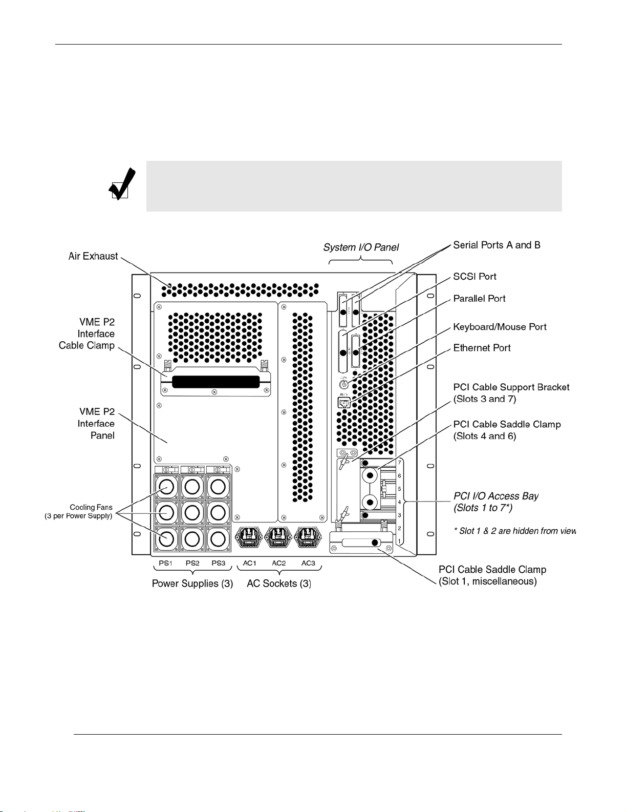
Primary I/O to and from the RES-204 is carried out from the rear of the system
through connectors attached to the System I/O Panel (see Figure 1-4). A description
of these connections is contained in Table 1-2 on page 1-6.
Note: Of the seven (7) PCI I/O slots accessible from the rear of the RES-204, slot
2 is reserved for the VME-Bridge PCI Card, and slot 5 is unoccupied.
1-4
Figure 1-4.
RES-204 Components (Rear View)
Themis Computer
Page 29
1—Product Overview
Basic Design
Table 1-1.
Major Components of the RES-204
RES-204 Components Quantity Performance / Characteristics
z 450 MHz
z 4-MB L2 Cache
z 4 GigaBytes
(256-MB DIMMs)
Server
Subsystem
(Ultra 80
Motherboard)
UltraSPARC-II
CPU Module
DIMM
Module
4
16 slots
(8 x 2 banks,
fast-page mode)
PCI
I/O Slots
UPA Graphics I/O
Slots
Ultrawide
SCSI Port
(40 MBytes/sec)
Parallel Port 1
4
z Slots 1, 2, 3 =
full-size
z Slot 4 = short
2*
2
z 1 slot @ 33 or 66 MHz; 32- or 64-bit bus, 3.3VDC
z 2 slots @ 33 MHz; 32- or 64-bit bus, 5VDC
z 1 slot @ 33 MHz; 32-bit bus, 5VDC
z Each slot @112.5 MHz;
64-bit UPA interface
z 1 channel for internal devices (CD-ROM and
disk drives, for example)
z 1 channel for external use
z DB25, female (Centronics-compatible)
z Extended Capability Port (ECP) support
Serial Ports 2
Ethernet Port 1
Keyboard/Mouse 1
Audio interface 4 pair + ground
VME I/O
Subsystem
VME I/O Slots (6U) 10**
System Power Supplies 3 (1 mandatory)
Peripherals CD-ROM Drive 1
Hard-Disk Drives
When UPA slot 2 is populated (with an Expert3D or Creator3D card, for example), PCI slot 1 cannot be used.
*
3 (1 mandatory
boot drive)
z DB25, female (synchronous/asynchronous)
z RJ45, 10/100 Base-T (Mbits/sec)
z Serial DIN
z 8 16-bit stereo channels (2 input, 2 output,
2 microphone, 2 earphone)
z 80 MB/second VME64 bus
z 400 watts each; autoranging; load sharing
z 32X
z 18 GB each drive
** The VME Buffer/Alarm Board must be installed in VME slot 1.
Themis Computer
1-5
Page 30
Rugged Enterprise Server 200 Installation Guide
Table 1-2. I/O Panel Connection IDs and Definitions
I/O Port ID Definition
Ultrawide SCSI z 40-Mbytes/second
Serial A (COM 1; DB25) A z Synchronous
and asynchronous
Serial B (COM 2; DB25) B
protocols
Parallel
(Centronics-compatible)
z Extended capability
port (ECP) support
z Keyboard and mouse
Keyboard / Mouse
functions are
combined through
one cable
Ethernet (RJ45) z 10/100-Mbits/second
Video 0 (13W3) with
Stereo Goggles
(left channel)
Video 1 (13W3) with
Stereo Goggles
(right channel)
Microphone
(2 channels)
z UPA graphics slot
(optional)
z UPA graphics slot
(optional)
z Stereo microphone
input
Audio In (2 channels) z Stereo audio input
Note:
• Cable clamps have been removed from this view.
• Slot 2 is reserved for the VME Buffer/Alarm Board.
• Slot 4 may be used for either a PCI card or a
graphics card, but not both.
1-6
Audio Out (2 channels) z Stereo audio output
Headphones
(2 channels)
z Stereo speaker
output
Power Supply 1
(not shown)
z Each power supply
Power Supply 2
(not shown)
socket is separately
fused (see Figure
1-4, page 1-4)
Power Supply 3
(not shown)
Themis Computer
Page 31

1.1.1.1 Custom VME P2 I/O Interface Panel
The RES-204 has room to add a second I/O panel (to the left of the System I/O
Panel; see Figure 1-4) that is custom-defined by the user to access P2 signals on the
backplane. Contact your authorized Themis distributor or the Themis Sales Department at (510) 252-0870 (Fax: 510-490-5529; Email: [email protected]).
[Details on System I/O Panel connectors, along with their signals and pin assignments, are given in Appendix C, “Connector Signal and Pinout Assignments”.]
Note: Additional I/O is carried out through the ports of each I/O card or board
installed on the Server Motherboard or VME Subsystem.
1.1.2 Memory System
The RES-204 Ultra 80 Motherboard provides sixteen slots for high-capacity dual
inline memory modules (DIMMs). Eight of the sixteen slots are located on the
Motherboard and the other eight memory slots are located on the Memory Riser
Assembly. The system supports Sun standard 168-pin, 5-volt, 60-nanosecond
DIMMs, of which 16-, 32-, 64-, 128-, and 256-Mbyte capacities can be installed. but
only DIMMs of 64- and 256-Mbyte capacities are supported. Total supported system
memory capacity ranges from 256 Mbytes to 4 Gbytes.
1—Product Overview
Basic Design
Themis Computer
Memory slots are organized into four banks (bank 0 through bank 3), with each bank
comprising four slots. Each bank is divided between the Motherboard and the memory riser assembly. Consequently, the DIMMs must be installed in groups of four,
with two DIMMs being installed in a Motherboard bank, and the second set of two
DIMMs being installed in the associated memory riser assembly bank.The system
reads from, or writes to, all four DIMMs in a bank at the same time.
The memory system (see Figure 1-5) consists of four components: the QSC ASIC,
the XB9++ ASIC, the CBT switching network, and the memory module.
The QSC ASIC generates memory addresses and control signals to the memory
module. The QSC ASIC also coordinates the two 288-bit-wide data bus
{MEM_DAT0 and MEM_DAT1) data transfers between the XB9++ ASIC. Coordination is provided by the BANK_SEL control signal to the CBT switching network.
The XB9++ ASIC exchanges 144-bit-wide bus data with the two CPU data buses:
UPA_DATA0 and UPA_DATA1; exchanges 64-bit-wide bus (UPA_E_DAT) data
with the two UPA graphic slots; and exchanges 72-bit-wide bus (UPA_D_DAT)
data with the U2P ASIC. This data is placed on a 576-bit-wide bus and exchanged
1-7
Page 32
Rugged Enterprise Server 200 Installation Guide
Figure 1-5. Memory System Functional Block Diagram
with the CBT switching network where it is divided on to two 276-bit-wide data
buses and exchanged with the memory module.
Figure 1-6 on page 1-9 illustrates the memory module arranged in four banks; 0, 1,
2, and 3. Figure 1-7, page 1-9, shows the DIMM slot mapping for the Motherboard
and the memory riser assembly.
1.1.2.1 Memory Interleaving
Whenever banks 0 and 1 are populated with identical capacity DIMMs and banks 2
and 3 are empty, memory reads and writes are automatically interleaved between the
two banks. This is called two-way interleaving. Two-way interleaving significantly
reduces the average memory latency, thus improving overall system performance.
When all four banks contain identical capacity DIMMs, the system interleaves
across all four banks (called four-way interleaving), to further reduce average memory latency.
The system can operate with memory DIMMs of different capacities in different
banks (for example four 64-Mbyte DIMMs in bank 0 and four 256-Mbyte DIMMs in
bank 1), but for improved performance, populate all banks with DIMMs of identical
capacity.
1-8
For maximum performance, install identical capacity DIMMs in all four memory
Themis Computer
Page 33
1—Product Overview
Basic Design
Figure 1-6. Memory Module Functional Block Diagram
Themis Computer
Figure 1-7. DIMM Mapping
1-9
Page 34
Rugged Enterprise Server 200 Installation Guide
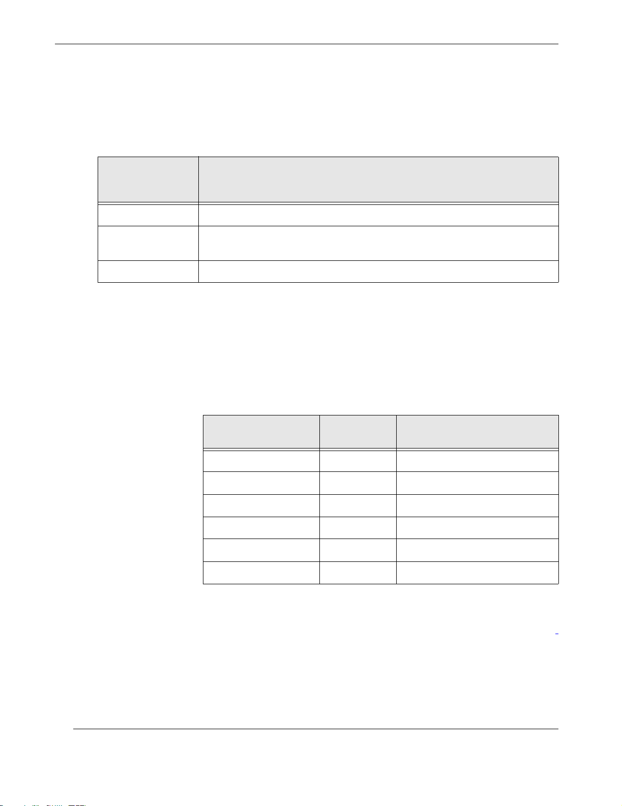
banks. Table 1-3 on page 1-10 lists how to best populate the memory banks when
configuring the system for 1 Gbyte of memory.
Table 1-3.
Memory
Performance
Level
Good Bank 0 has four, 64-Mbyte DIMMs (no interleaving)
Better
Best Banks 0, 1, 2, and 3 all have four 64-Mbyte DIMMs (4-way interleaving)
Banks 0 and 1 each have four 64-Mbyte DIMMs and banks 2 and 3 are empty
(2-way interleaving)
Memory Slot Population
1-Gbyte DIMM Configuration Scenario
Table 1-4 lists the starting relative address of memory with no interleaving with four
DIMMs of a particular size being installed in a particular memory bank. For
instance, if four 64-Mbyte DIMMs are in bank 0, the relative starting addresses are
from 0 x 0000.0000 to 0 x 0fff.ffc0. Likewise, if four 256-Mbyte DIMMs are in bank
2, the relative starting addresses are from 0 x 8000.0000 to 0 x bfff.ffc0.
Table 1-4. Memory Relative Starting Address with No Interleaving
DIMM Size/Quantity
Memory
Bank
Addressing
1-10
64-Mbyte/4 0 0 x 0000.0000 to 0 x 0fff.ffc0
64-Mbyte/4 1 0 x 4000.0000 to 0 x 4fff.ffc0
64-Mbyte/4 2 0 x 8000.0000 to 0 x 8fff.ffc0
64-Mbyte/4 3 0 x c000.0000 to 0 x cfff.ffc0
256-Mbyte/4 0 0 x 0000.0000 to 0 x 3fff.ffc0
256-Mbyte/4 1 0 x 4000.0000 to 0 x 7fff.ffc0
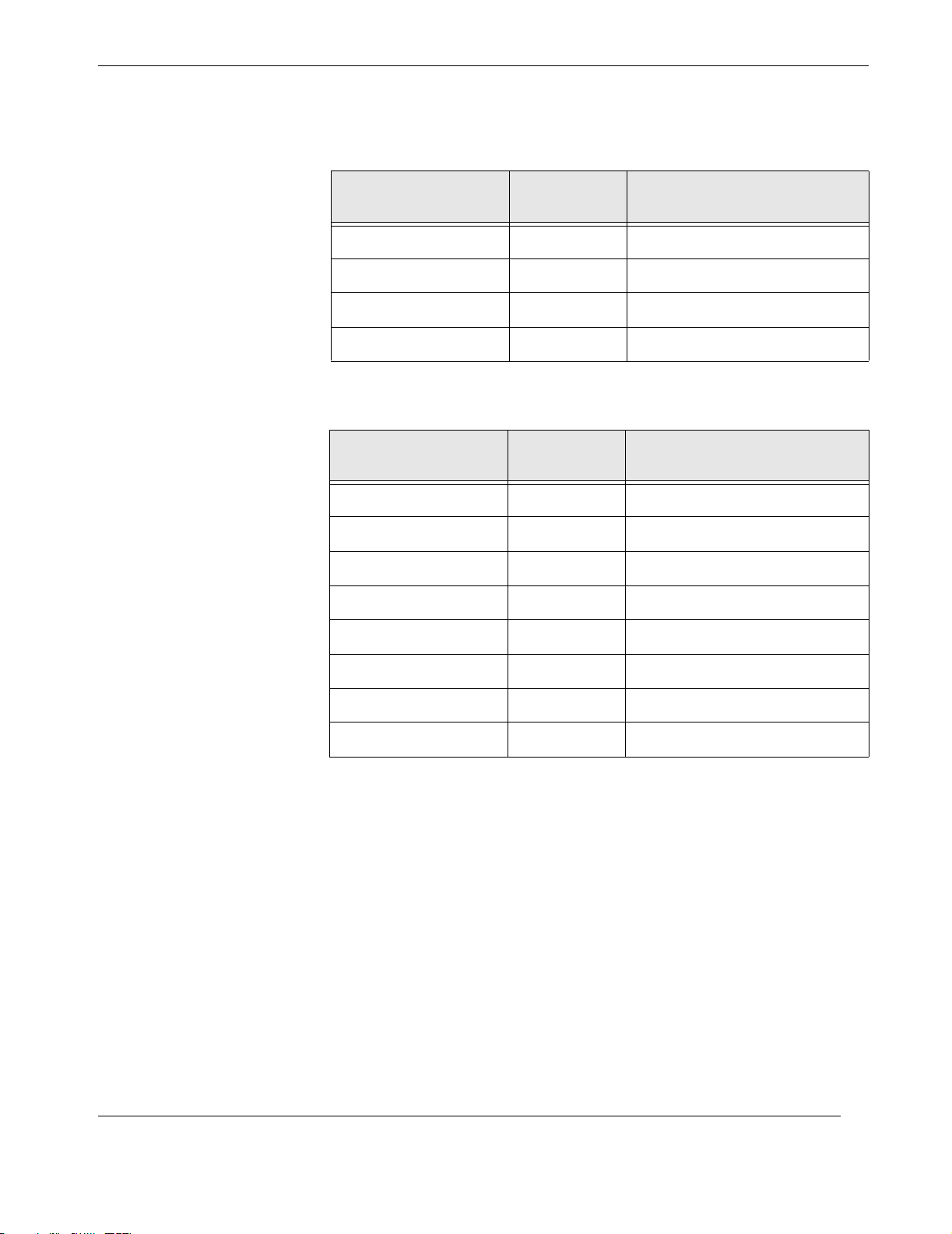
Table 1-5, page 1-11, lists memory addressing with 2-way interleaving with eight
DIMMs of a particular size being installed in banks 0 and 1. Table 1-6, page 1-11,
lists memory addressing with 4-way interleaving with 16 DIMMs of a particular size
being installed in banks 0, 1, 2, and 3.
Themis Computer
Page 35
1—Product Overview
Basic Design
Table 1-5.
DIMM Size/Quantity
64-Mbyte/4 0 0 x 0000.0000 to 0 x 1fff.ff80
64-Mbyte/4 1 0 x 0000.0040 to 0 x 1fff.ffc0
256-Mbyte/4 0 0 x 0000.0000 to 0 x 3fff.ffff)
256-Mbyte/4 1 0 x 0000.0040 to 0 x 7fff.ffco
Memory Addressing for 2-Way Interleaving
Memory
Bank
Addressing
Table 1-6. Memory Addressing for 4-Way Interleaving
DIMM Size/Quantity
64-Mbyte/4 0 0 x 0000.0000 to 0 x 3fff.ff00
64-Mbyte/4 1 0 x 0000.0040 to 0 x 3fff.ff40
64-Mbyte/4 2 0 x 0000.0080 to 0 x 3fff.ff80
Memory
Bank
Addressing
64-Mbyte/4 3 0 x 0000.00c0 to 0 x 8fff.ffco
256-Mbyte/4 0 0 x 0000.0000 to 0 x ffff.ff00
256-Mbyte/4 1 0 x 0000.0040 to 0 x ffff.ff40
256-Mbyte/4 2 0 x 0000.0080 to 0 x ffff.ff80
256-Mbyte/4 3 0 x 0000.00c0 to 0 x ffff.ffc0
1.1.2.2 Memory System Timing
The QSC ASIC generates the memory addresses and control signals to the memory
system. The UPA clock is the clock source for the QSC ASIC and operates as fast as
120 MHz.
Themis Computer
1-11
Page 36

Rugged Enterprise Server 200 Installation Guide
1-12
Themis Computer
Page 37
Installation
2
Section
Major Assembly Installation
This chapter shows how to remove and replace major assemblies of the RES-204.
2.1 Server Subsystem Assembly
The Server Subsystem Assembly (see Figure 2-1, page 2-2) must first be removed
from the RES-204 before installing or removing any of the following Ultra 80 Motherboard (see Figure 2-2, page 2-3) components (online readers may click on the
page link to go directly to the appropriate section):
Chapter
Themis Computer
2.1.1 Powering Off the System............................................................................ 2-2
2.1.2 Removing the Server Assembly ................................................................. 2-4
2.1.3 Jumper-Pin Configurations ......................................................................... 2-8
2.1.4 CPU Module ............................................................................................. 2-10
2.1.5 PCI Card ................................................................................................... 2-14
2.1.6 UPA Graphics Card .................................................................................. 2-16
2.1.7 DIMM ....................................................................................................... 2-20
2.1.8 Audio Module Assembly .......................................................................... 2-29
2.1.9 NVRAM/TOD Assembly ......................................................................... 2-31
2.1.10 DC-to-DC Converter Assembly................................................................ 2-33
2-1
Page 38
Rugged Enterprise Server 200 Installation Guide
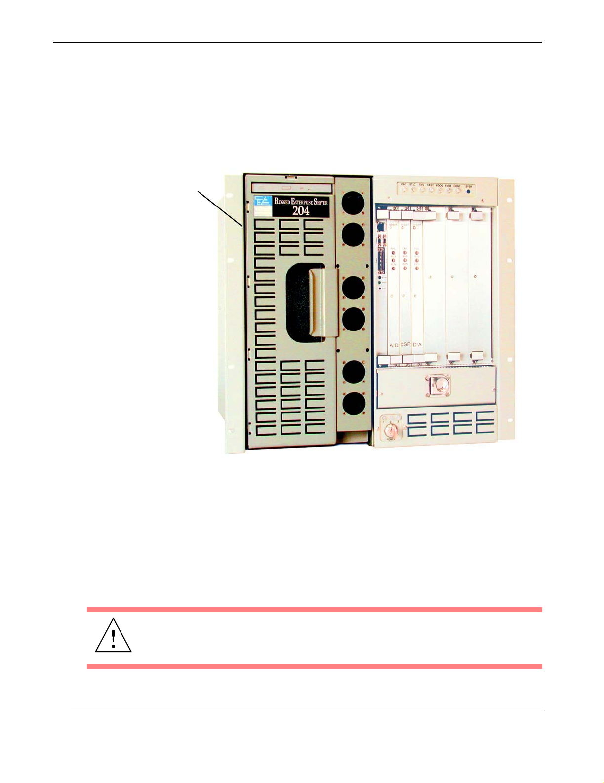
Before proceeding with the removal of the Server Subsystem Assembly, the system
must be properly backed up and powered off (see next section). After the system has
been powered off, remove the Server Assembly and go to the section of this chapter
for the component to be installed, replaced, or removed.
Server Subsystem Assembly
Figure 2-1. The RES-204 Server Subsystem Assembly
2.1.1 Powering Off the System
1. Back up all system files and data according to standard operating-system protocols.
2. “Halt” the system from the command line of your terminal to return to the
“OK” prompt.
Caution: Prior to turning off system power, exit from the operating system. Failure
to do so may result in loss of data.
2-2
Themis Computer
Page 39
Top of Board
2—Major Assembly Installation
Server Subsystem Assembly
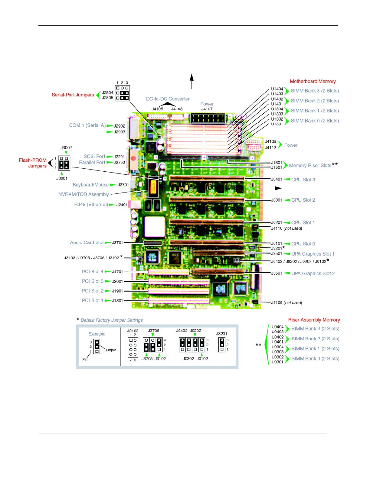
Front of Board
Themis Computer
Figure 2-2. The Ultra 80 Motherboard
2-3
Page 40
Rugged Enterprise Server 200 Installation Guide
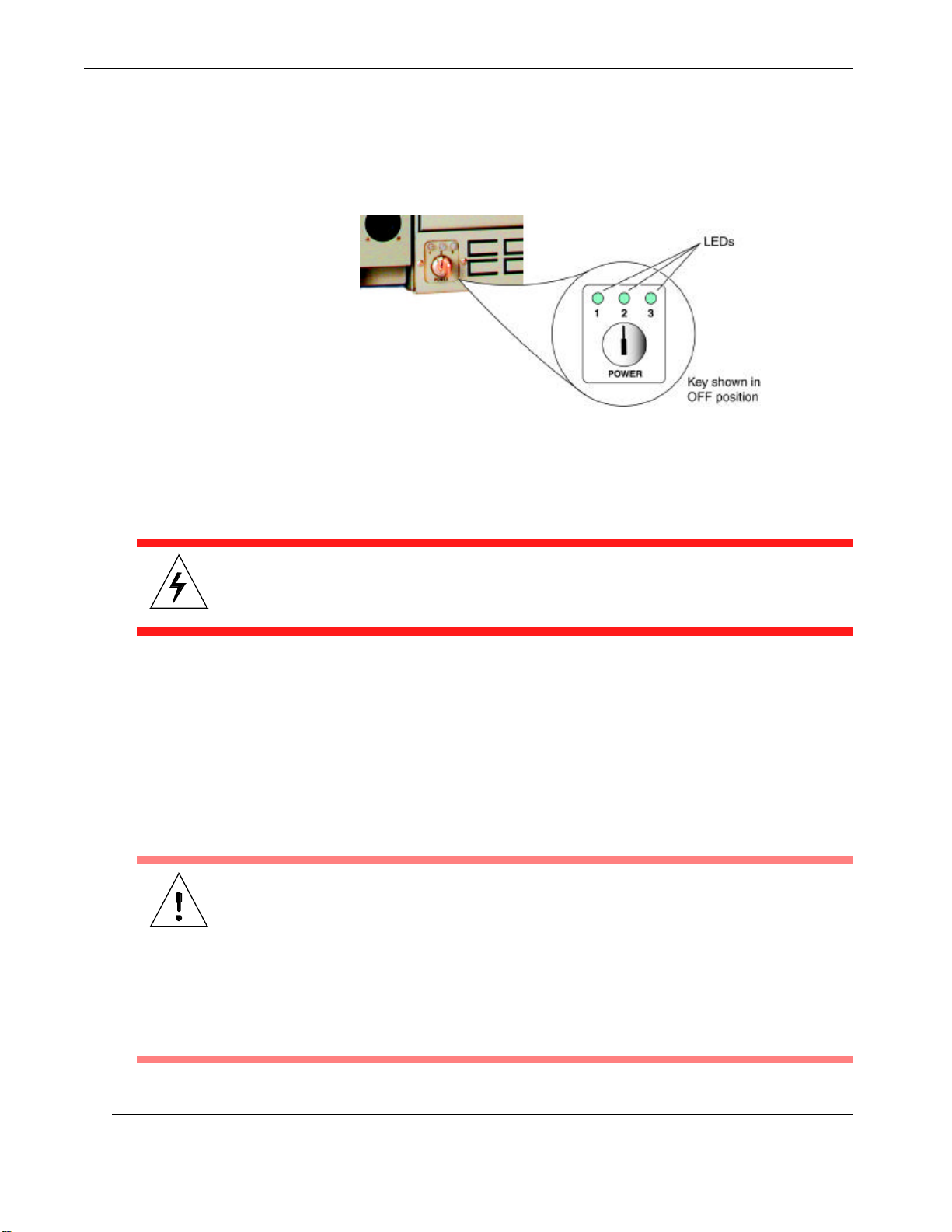
3. Power off the system by turning the key-switch to the OFF position (see Figure
2-3 and Chapter 4, "Managing Your System" for details on system LEDs).
Figure 2-3. Turn the RES-204 Key-Switch to the OFF Position
Important: Remember that the power key itself has two positions only—ON
when turned clockwise (vertical), and OFF when turned counterclockwise.
Warning: Turning the system OFF does not remove power from the system. To remove all power from the system, disconnect all power cords.
2.1.2 Removing the Server Assembly
1. Release the four Phillips-head screws holding the disk-tray dust cover to the
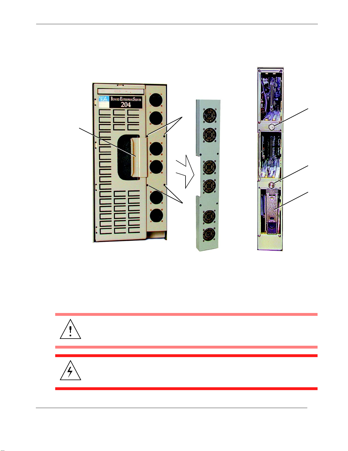
Server Subsystem Assembly and remove the cover (see A, Figure 2-4 on page
2-5).
2. Using a 1/2-inch socket driven by a ratchet wrench, unloosen the two hexhead bolts holding the Assembly to the cabinet (see B, Figure 2-4, page 2-5).
Caution: When removing the two hex-head bolts, alternate from one bolt to the
other after three (3) full turns on each until they are fully loosened. Failure to follow
this procedure may cause the Assembly to bind and/or damage the bolts.
The two hex bolts are captive, hence cannot be removed from the Assembly. If a
bolt has not been fully released, continue to turn it counter-clockwise.
Repeat this procedure (alternate tightening of bolts) when reinstalling the Server
Assembly.
2-4
Themis Computer
Page 41
Assembly
Handle
2—Major Assembly Installation
Server Subsystem Assembly
Disk-Tray
Dust cover
1/2-inch
Screws (2)
Remove
Cover
Hex Bolt
1/2-inch
Hex Bolt
Hard-Disk
Drive
Screws (2)
Disk Tray
B
Figure 2-4.
A
Remove the Disk-Tray Dust Cover and Loosen Assembly Bolts
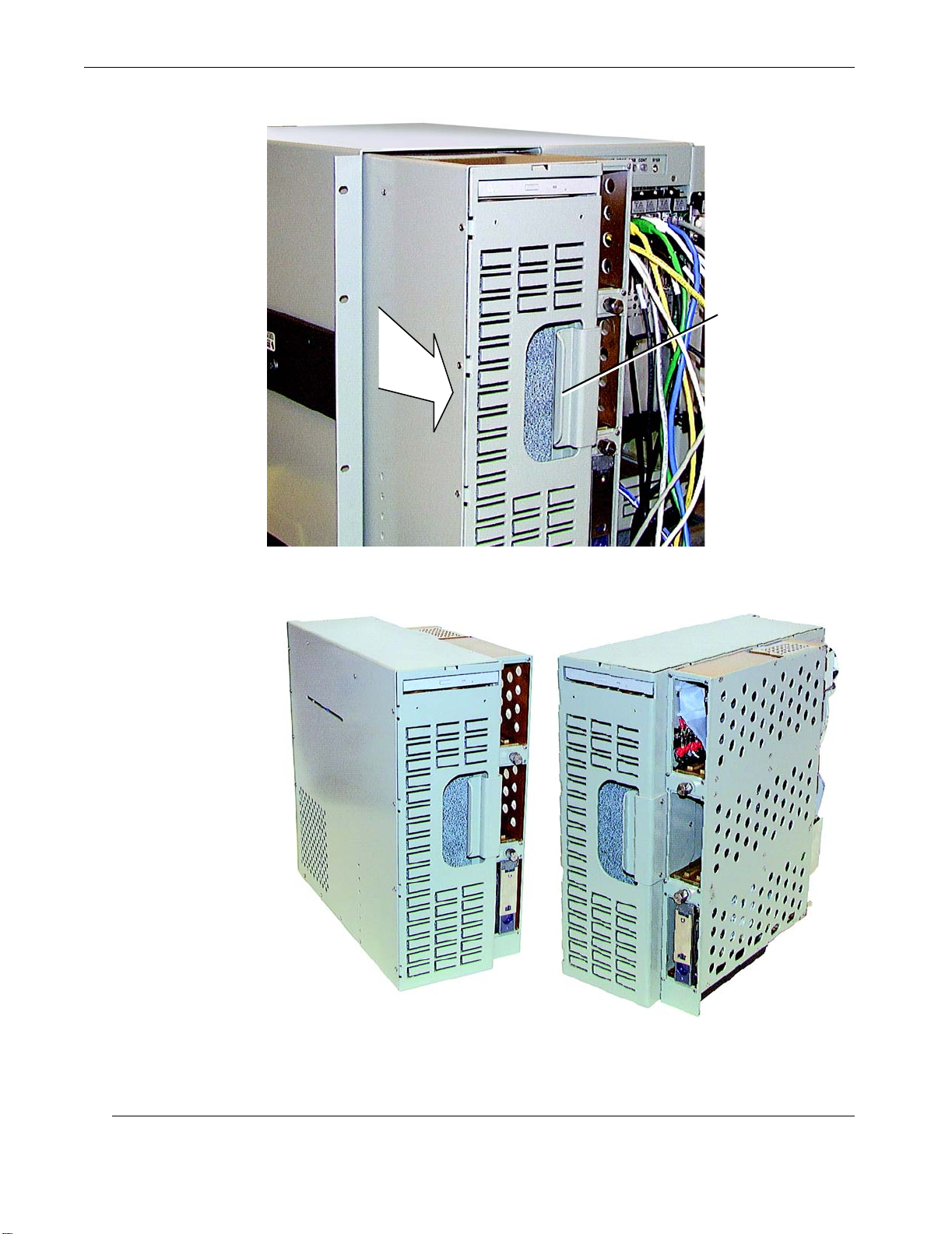
3. Firmly grasping the Assembly handle, pull the Server Subsystem until it is almost out of its enclosure (see Figure 2-5, page 2-6).
Caution: To protect the Server Subsystem from falling, support it from the bottom
as it is pulled from the RES-204 cabinet.
Themis Computer
Warni ng : Use proper ESD grounding techniques when handling components.
Wear an antistatic wrist strap and use an ESD-protected mat. Store ESD-sensitive
components in antistatic bags before placing them on any surface.
2-5
Page 42
Rugged Enterprise Server 200 Installation Guide
Pull
Assembly Handle
Forward
(Hold bottom to
prevent Assembly
from falling)
Figure 2-5. Remove the Server Subsystem Assembly
2-6
AB
Figure 2-6. Left- (A) and Right-Hand Views of Removed Server Assembly
Themis Computer
Page 43
2—Major Assembly Installation
Server Subsystem Assembly
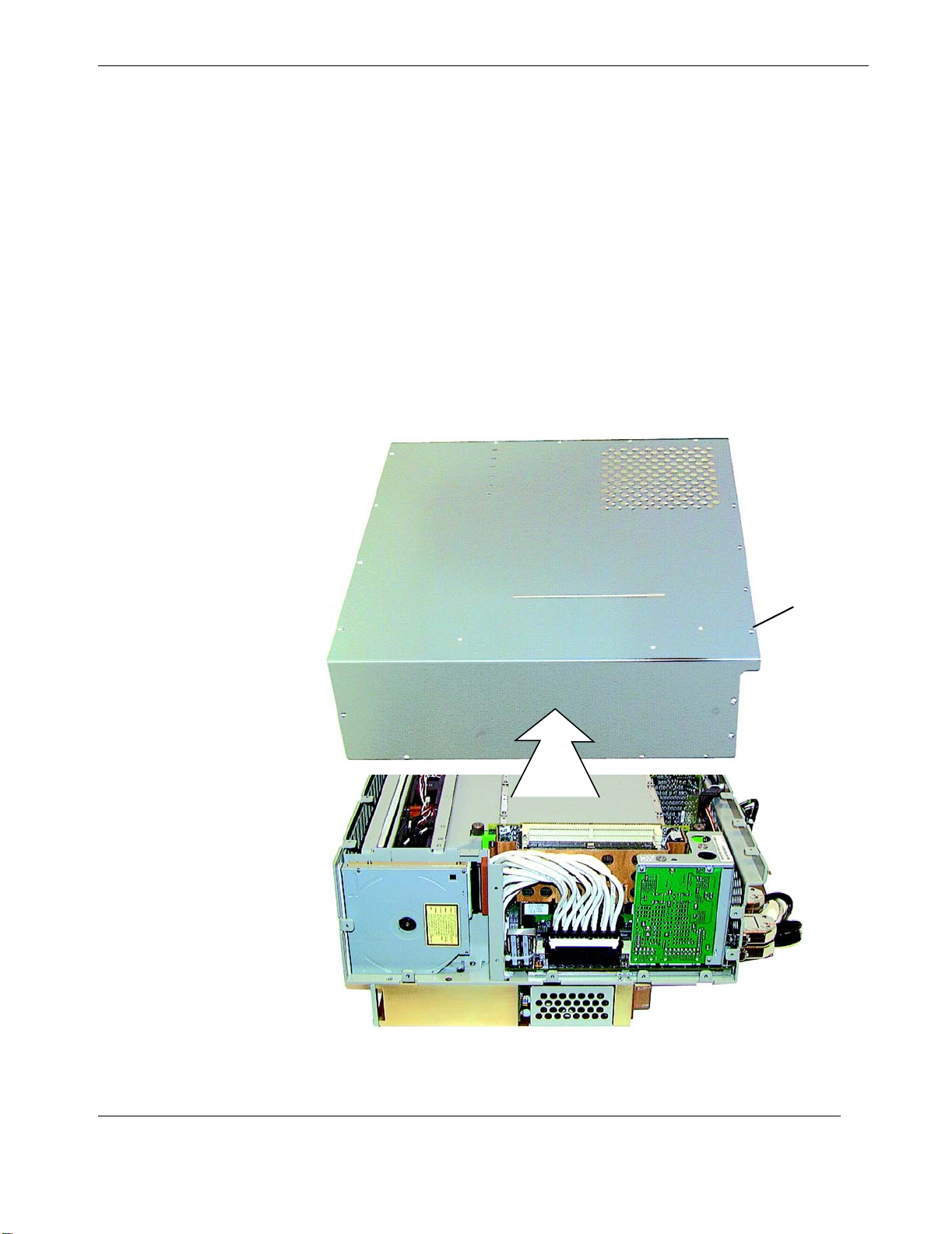
Figure 2-6 shows both sides of the removed Server Subsystem Assembly.
4. Lay the Server Assembly on its right side to access its protective cover plate.
5. Loosen and remove each of the 22 Phillips-head screws securing the Server
Assembly cover plate (see Figure 2-7).
6. Removal of the Server Assembly protective cover plate will expose most of
the Motherboard slots and connectors used for major components.
Go to the following sections to:
• Configure the Motherboard jumper-pins
• Install, remove, or replace a particular component or module
Cover Plate
Server Subsystem Assembly
(open)
Screw Hole
(22 total)
Themis Computer
Figure 2-7. Remove the Server Assembly Protective Cover Plate
2-7
Page 44
Rugged Enterprise Server 200 Installation Guide
2.1.3 Jumper-Pin Configurations
Caution: Use proper ESD grounding techniques when handling components.
Wear an antistatic wrist strap and use an ESD-protected mat. Store ESD-sensitive
components in antistatic bags before placing them on any surface.
Handle the Motherboard by the back panel or edges only.
2.1.3.1 Serial-Port Configuration
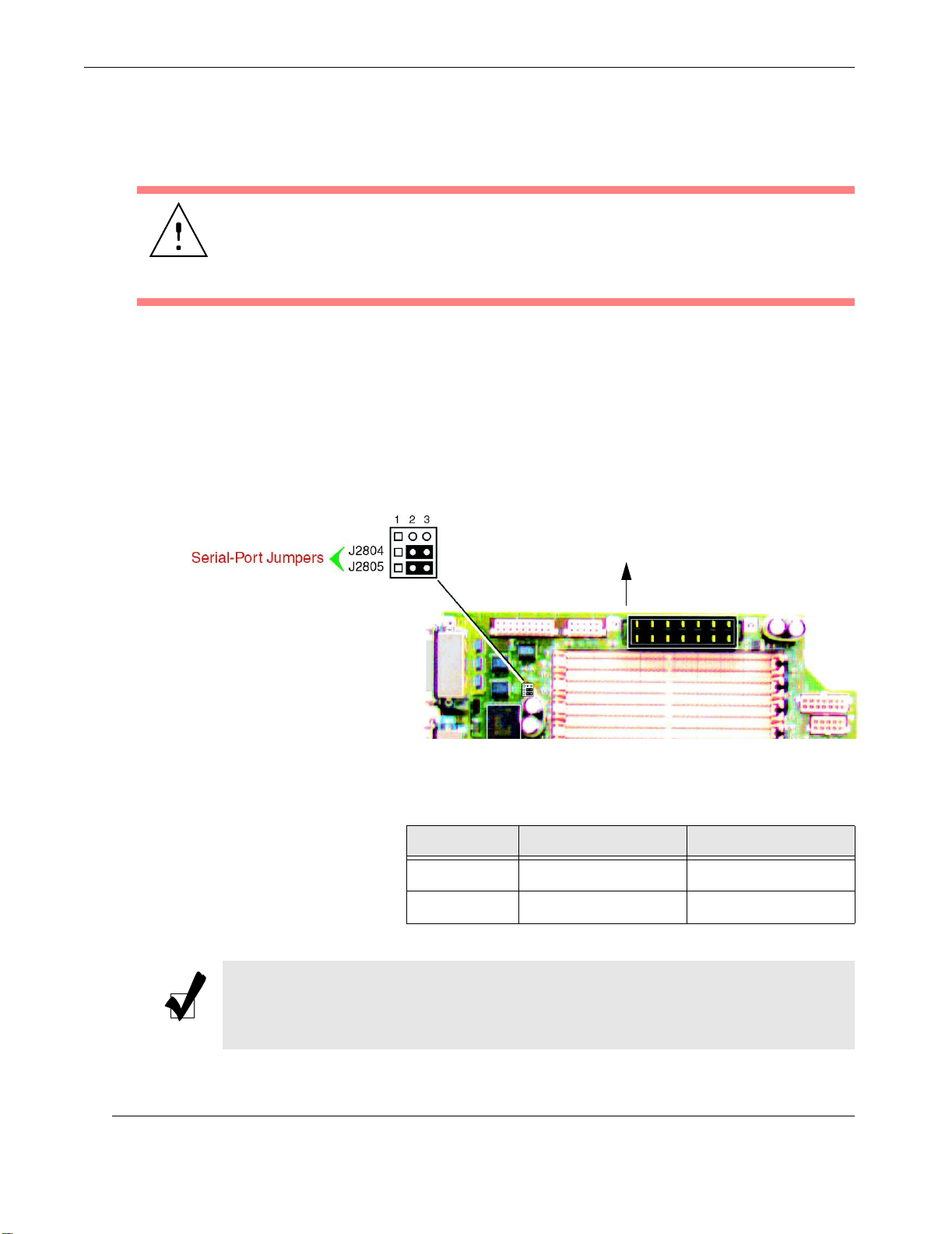
1. Using long-nose pliers, set the Motherboard serial-port jumpers J2804 and
J2805 according to Figure 2-8 and Table 2-1. Jumpers J2804 and J2805 can
be set to either an RS-423 (default) or RS-232 serial interface. The jumpers
are preset for RS-423. RS-232 is required for digital telecommunication within the European Community.
Top of Board
Figure 2-8. Location of the Motherboard Serial-Port Jumpers
Table 2-1. Serial-Port Jumper Settings
Jumper Select Pins 1 + 2
J2804 RS232 RS423 [default]
J2805 RS232 RS423 [default]
Select Pins 2 + 3
Note: Jumpers J2804 and J2805 can be set to either RS-423 (default) or RS-232
serial interface. The jumpers are preset for RS-423. RS-232 is required for digital
telecommunication within the European community.
2-8
Themis Computer
Page 45
Note: Motherboard jumper-pins are identified with a reference designation—an
asterisk—located on the PCB surface immediately adjacent to jumper-pin 1. In
the diagrams of this manual, pin 1 is indicated with a square.
2.1.3.2 Flash-PROM Configuration
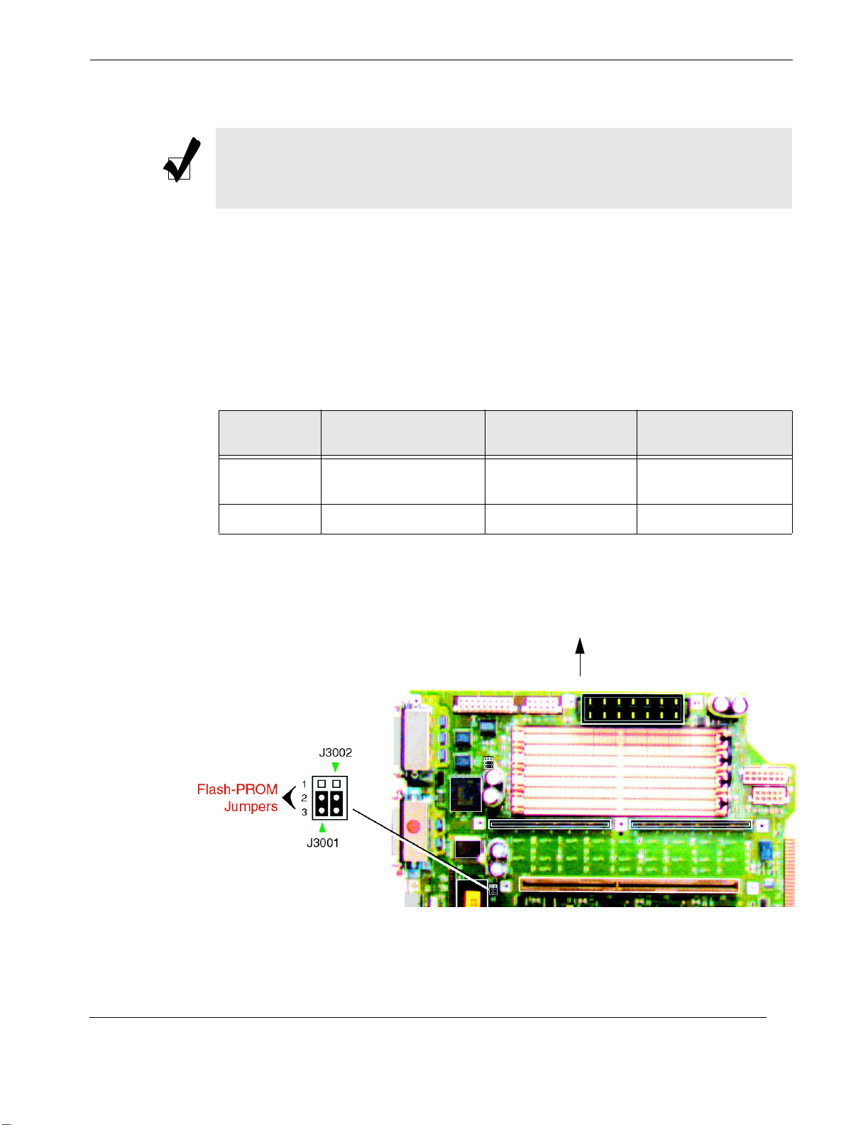
Flash PROM jumpers J3001 and J3002 are for reprogramming specific code blocks
and remote programming of the flash PROM. Table 2-2 identifies the flash-PROM
jumper settings. Figure 2-9 shows the location of the jumper-pins.
1. Using long-nose pliers, set the Motherboard flash-PROM jumpers J3001 and
J3002 according to Table 2-2.
2—Major Assembly Installation
Server Subsystem Assembly
Table 2-2. Flash-PROM Jumper Settings
Jumper-
Pins
J3001 Write protect (default) Write Enable
J3002 Select (default) No select XOR LOGIC SET
Jumper on
Pins 1 + 2
Jumper on
Pins 2 + 3
Signal Controlled
FLASH PROM
PROG ENABLE
Top of Board
Themis Computer
Figure 2-9. Location of the Motherboard Flash-PROM Jumpers
2-9
Page 46
Rugged Enterprise Server 200 Installation Guide
2.1.4 CPU Module
Warni ng : Use proper ESD grounding techniques when handling components.
Wear an antistatic wrist strap and use an ESD-protected mat. Store ESD-sensitive
components in antistatic bags before placing them on any surface.
2.1.4.1 Installing and Removing a CPU Module
1. Power off the system (see “Powering Off the System”, page 2-2) and remove
the Server Subsystem Assembly (see “Removing the Server Assembly”, page
2-4, including its protective cover plate).
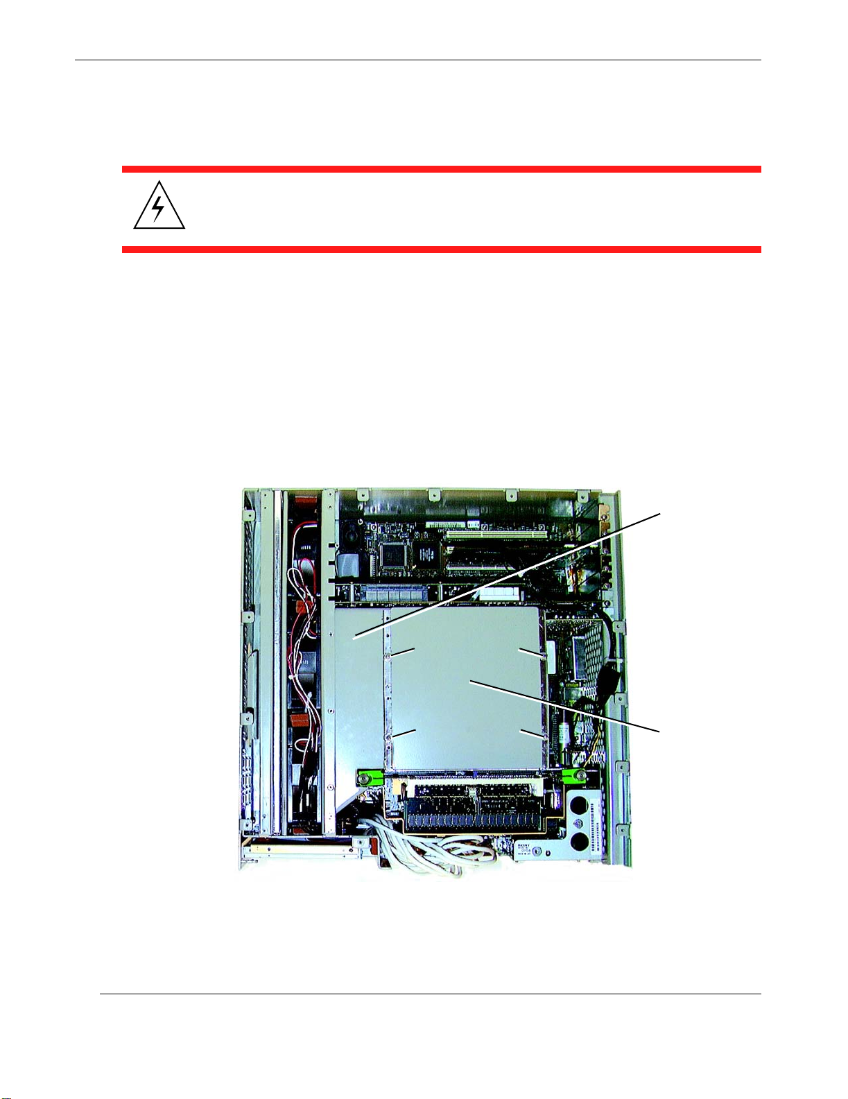
2. Loosen and remove the four Phillips-head screws that secure the CPU Module
Cover Plate, then remove the Cover Plate (see Figure 2-10 and Figure 2-11,
page 2-11).
Screw
Screw
Screw
Screw
CPU Module Air Guide
CPU Module Cover Plate
2-10
Figure 2-10. Remove Screws holding the CPU Module Cover Plate
Themis Computer
Page 47
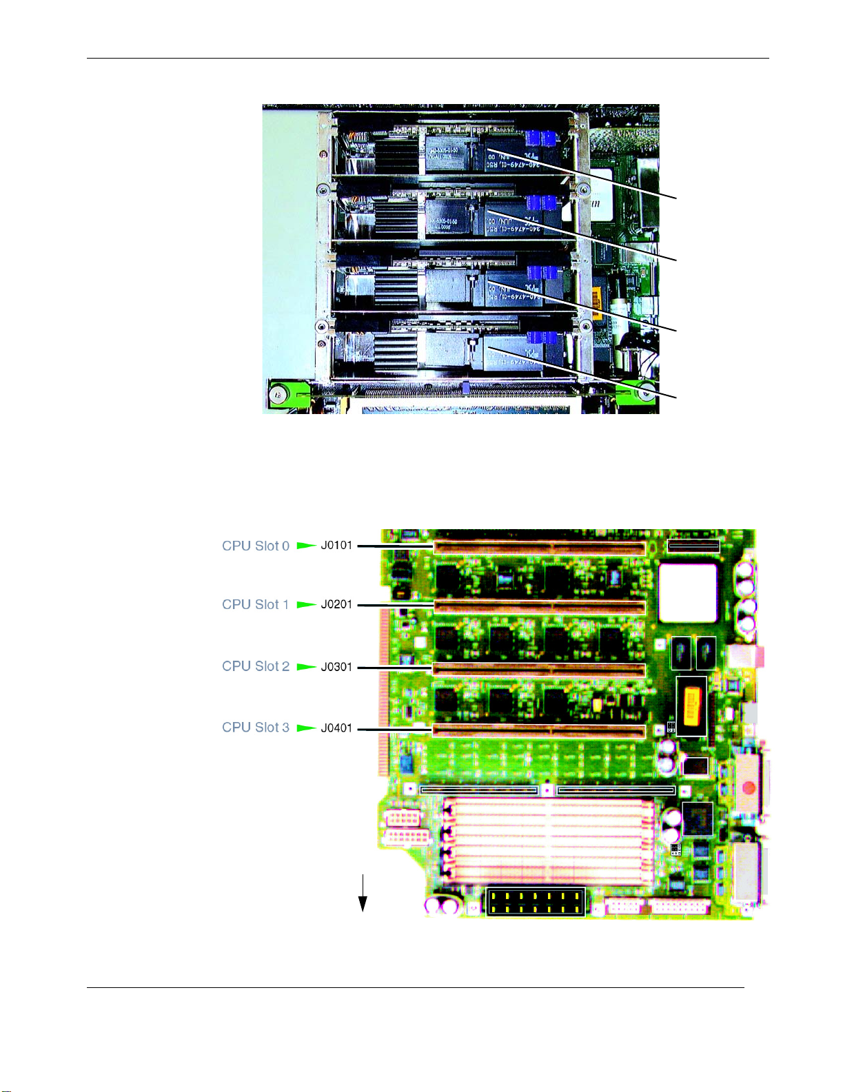
Figure 2-11. CPU Module Cover Plate Removed
2—Major Assembly Installation
Server Subsystem Assembly
CPU Module 0
CPU Module 1
CPU Module 2
CPU Module 3
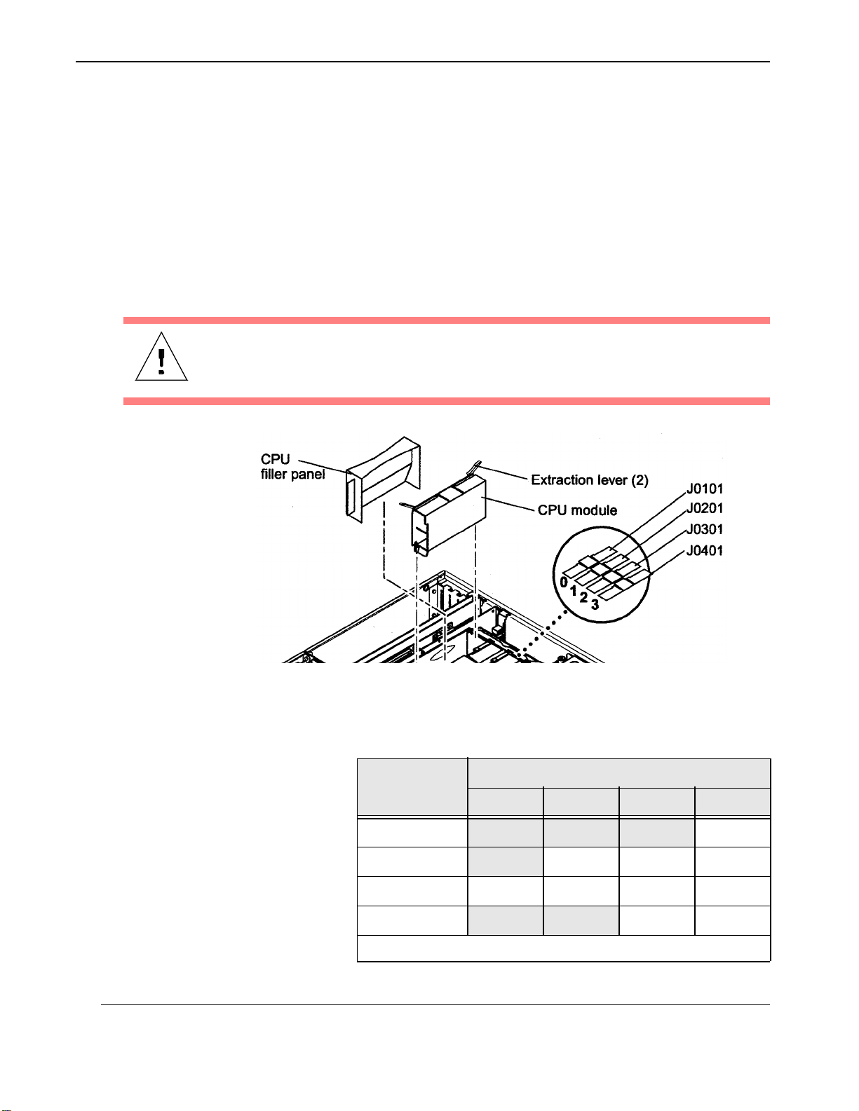
3. Locate the CPU Module slot (0, 1, 2, or 3) on the Motherboard (see Figure
2-11 and Figure 2-12).
Top of Board
Themis Computer
Figure 2-12. Locate the CPU Module Slot
2-11
Page 48
Rugged Enterprise Server 200 Installation Guide
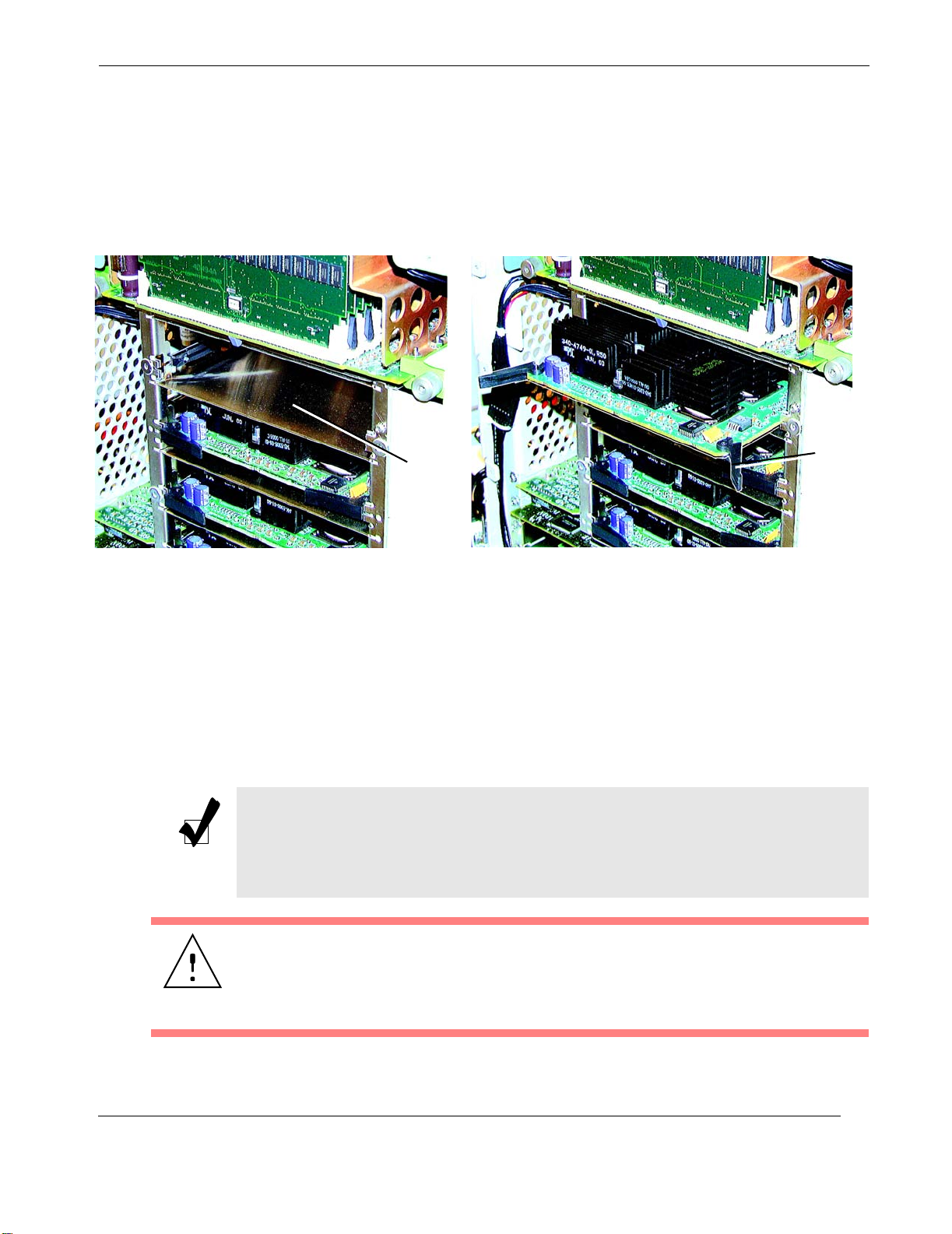
4. Installation Only. If you are installing a CPU Module, move the extraction
levers to the 135-degree position (see Figure 2-13 and Figure 2-14, page 2-
13), insert it into the appropriate slot (Table2-3), lower the CPU Module
along the vertical plastic guides, and press firmly until seated. Push the two
extraction levers on the CPU module toward the middle until they are locked
in place.
Important: CPU Modules must be installed according to the slot allocations
indicated in Table2-3. Any other CPU allocation will result in faulty operation and damage to the CPU.
Caution: After the CPU Module is seated, press it firmly downward until a “snap”
is heard; this indicates that the Module is properly seated.
2-12
Figure 2-13. Locate and Remove the CPU Module
Table 2-3. Order of CPU Module Installation
CPU Module
Slot
Slot 0 YES
Slot 1 YES YES YES
Slot 2* YES YES YES YES
Slot 3 YES YES
*A CPU Module must be installed in slot 2.
Total Number of CPUs to be Installed
1 2 3 4
Themis Computer
Page 49
2—Major Assembly Installation
Server Subsystem Assembly
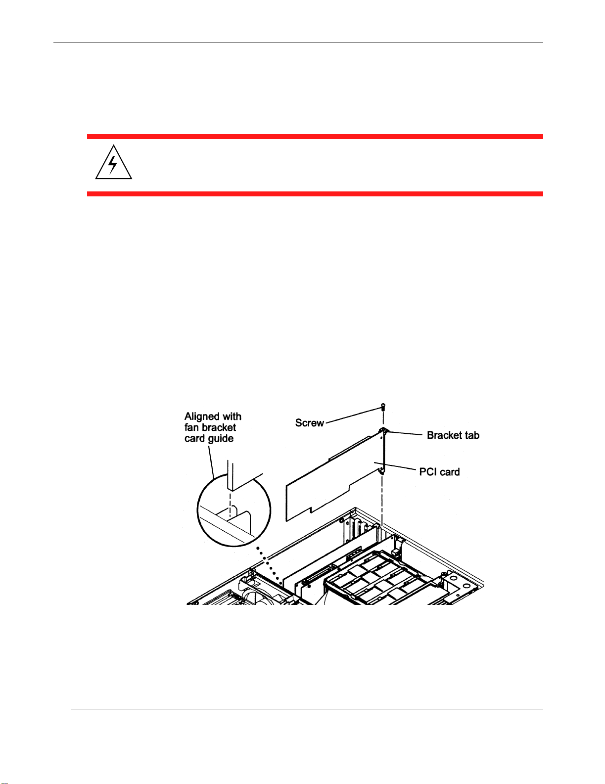
5. Removal Only. Using the thumbs of both hands, simultaneously lift the two
extraction levers on the CPU Module up and away to approximately 135-degrees (see Figure 2-14) Lifting the extraction levers may require more force
than you think is necessary, but continue to pull until the levers are free.
Extraction
Empty
slot
lever (2)
AB
Figure 2-14. Installing or Removing a CPU Module
Pull the CPU Module out until it clears the chassis and place it on an antistatic mat.
Important: Remember to follow the CPU slot allocation indicated in
Table 2-3. Any other CPU allocation will result in faulty operation and damage to the CPU.
Note: All CPU modules in the system must be of the same clock speed. When
installing CPU modules, fill the CPU slots in this order: 2, 1, 3, 0. Slot 0 is closest
to the system bottom when the CPU air guide is oriented on the right side of the
CPU shroud.
Caution: To ensure proper system cooling, any unused CPU slot(s) must contain a
CPU filler panel in place of a CPU Module.
Remember to replace the CPU Module Cover Plate and the four screws that secure
it when installation or removal of a CPU Module has been completed.
Themis Computer
2-13
Page 50
Rugged Enterprise Server 200 Installation Guide
2.1.5 PCI Card
Warni ng : Use proper ESD grounding techniques when handling components.
Wear an antistatic wrist strap and use an ESD-protected mat. Store ESD-sensitive
components in antistatic bags before placing them on any surface.
2.1.5.1 Installing a PCI Card
1. Power off the system (see “Powering Off the System”, page 2-2) and remove
the Server Subsystem Assembly (see “Removing the Server Assembly”, page
2-4), including its protective cover plate.
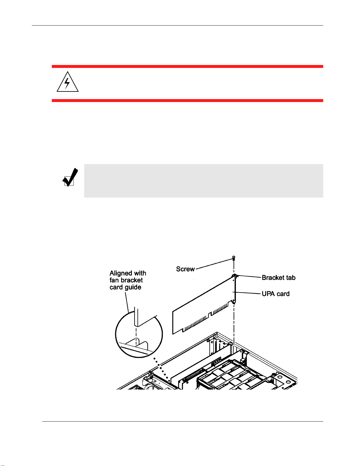
2. Position the PCI card over one of the four slots on the Motherboard.
3. Guide the card bracket tab into the chassis back-panel opening; guide the op-
posite end of the card into the fan bracket card guide so that the card is aligned
evenly with the Motherboard slot (see Figure 2-15).
2-14
Figure 2-15. Placement of the PCI Card
4. At the two upper corners of the PCI card, push the PCI card straight down into
the slot until the PCI card is fully seated.
Themis Computer
Page 51
5. Using a No. 2 Phillips screwdriver, replace the screw securing the PCI card
bracket tab to the system chassis.
6. Connect cables to all PCI connectors.
Note: Read the PCI card product guide for information about jumper or switch
settings, slot requirements, and required tools.
2.1.5.2 Removing a PCI Card
1. Power off the system (see “Powering Off the System”, page 2-2) and remove
the Server Subsystem Assembly (see “Removing the Server Assembly”, page
2-4), including its protective cover plate.
2. Disconnect all external cables from the PCI card being removed.
3. Using a No. 2 Phillips screwdriver, remove the screw securing the PCI card
bracket tab to the system chassis.
2—Major Assembly Installation
Server Subsystem Assembly
4. Pull the upper two corners of the card straight up from the slot and remove it
from the chassis.
5. Place the PCI card on an antistatic mat.
Themis Computer
2-15
Page 52
Rugged Enterprise Server 200 Installation Guide
2.1.6 UPA Graphics Card
Warni ng : Use proper ESD grounding techniques when handling components.
Wear an antistatic wrist strap and use an ESD-protected mat. Store ESD-sensitive
components in antistatic bags before placing them on any surface.
2.1.6.1 Installing a Graphics Card
1. Power off the system (see “Powering Off the System”, page 2-2) and remove
the Server Subsystem Assembly (see “Removing the Server Assembly”, page
2-4), including its protective cover plate.
Note: Some UPA Graphics cards have a double-row connector that requires two
levels of insertion. When installing this graphics card, ensure that each connector
is fully seated into its slot.
2. Position the UPA Graphics card over one of the two slots on the Motherboard.
3. Guide the card bracket tab into the chassis back-panel opening; guide the op-
posite end of the card into the fan bracket card guide so that the card is aligned
evenly with the Motherboard slot (see Figure 2-16).
2-16
Figure 2-16.
Placement of the Graphics Card
Themis Computer
Page 53
4. At the two upper corners of the PCI card, push the PCI card straight down into
the slot until the PCI card is fully seated.
5. Using a No. 2 Phillips screwdriver, replace the screw securing the PCI card
bracket tab to the system chassis.
6. Connect cables to all PCI connectors.
Note: Read the PCI card product guide for information about jumper or switch
settings, slot requirements, and required tools.
2.1.6.2 Removing a Graphics Card
1. Power off the system (see “Powering Off the System”, page 2-2) and remove
the Server Assembly (see “Removing the Server Assembly”, page 2-4), including its protective cover plate.
2—Major Assembly Installation
Server Subsystem Assembly
2. Disconnect all video cables from the Graphics card being removed.
3. Using a No. 2 Phillips screwdriver, remove the screw securing the Graphics
card bracket tab to the system chassis.
4. Pull the upper two corners of the card straight up from the slot and remove it
from the chassis.
5. Place the UPA Graphics card on an antistatic mat.
2.1.6.3 Elite3D UPA Graphics Card
Note: If you are installing or using the Solaris 2.6 5/98 operating environment,
and you are installing an Elite3D UPA Graphics card, see “Elite3D UPA Graphics
Card Patch Information”, page 2-19.
Installation
1. Power off the system (see “Powering Off the System”, page 2-2) and remove
the Server Subsystem Assembly (see “Removing the Server Assembly”, page
2-4), including its protective cover plate.
Themis Computer
2-17
Page 54
Rugged Enterprise Server 200 Installation Guide
Note: The Elite3D Graphics card has a double-row connector that requires two
levels of insertion. When installing this graphics card, ensure that the connector
is fully seated into the slot.
2. Position the Elite3D card over one of the four slots on the Motherboard.
3. Guide the card bracket tab into the chassis back-panel opening; guide the op-
posite end of the card into the fan bracket card guide so that the card is aligned
evenly with the Motherboard slot (see Figure 2-16 on page 2-16).
4. At the two upper corners of the Elite3D card, push the card straight down into
the slot until it is fully seated.
5. Using a No. 2 Phillips screwdriver, replace the screw securing the Elite3D
card bracket tab to the system chassis.
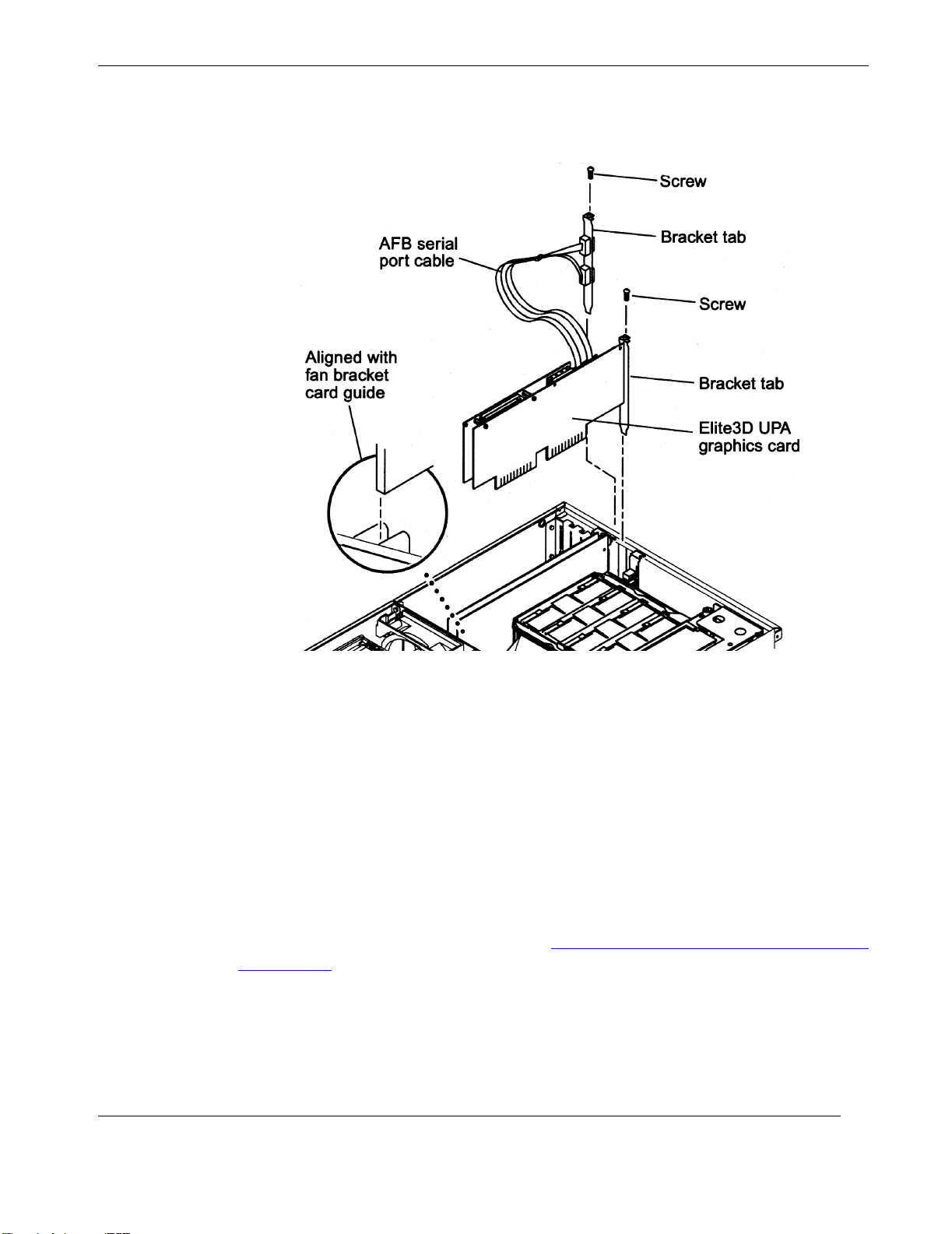
6. Insert the AFB serial port cable assembly bracket tab into an available chassis
PCI slot (see Figure 2-17 on page 2-19).
Note: Read the PCI card product guide for information about jumper or switch
settings, slot requirements, and required tools.
7. Using a No. 2 Phillips screwdriver, replace the screw securing the AFB serial
bracket tab to the system chassis.
8. Connect the two 10-position sockets to the mating connectors on the Elite3D.
9. Move the cables away from the adjacent PCI slot.
Note: One cable is shorter than the other to provide easy insertion. Sockets are
polarized and marked.
10. Connect the external video cable to the Graphics card video connector.
2-18
Themis Computer
Page 55
2—Major Assembly Installation
Server Subsystem Assembly
2.1.6.4 Elite3D UPA Graphics Card Patch Information
Themis Computer
Figure 2-17.
Placement of the Elite3D Card
If you are installing or using the Solaris 2.6 5/98 operating environment, and you are
also installing an Elite3D UPA graphics card, you must install the respective software patch:
• Solaris 2.6 5/98—After installing the Elite 3D UPA graphics card, software
patch 105363-06 (or a more current version of the patch, if available) should be
installed.
This patch is available through the upgrade CD included with your system (part 704-
6657), the SunSolve Online website at
index.html, or by contacting your authorized Themis representative.
http://www.sun.com/service/online/
2-19
Page 56
Rugged Enterprise Server 200 Installation Guide
2.1.7 DIMM
Use the following procedures to remove and replace a DIMM.
Warnin g : DIMMs consist of electronic components that are extremely sensitive to
static electricity. Ordinary amounts of static electricity from clothing or work environment can destroy the DIMM.
Warni ng : Use proper ESD grounding techniques when handling components.
Wear an antistatic wrist strap and use an ESD-protected mat. Store ESD-sensitive
components in antistatic bags before placing them on any surface.
Caution: When removing and replacing a single DIMM, an identical replacement
is required. The replacement DIMM must be inserted into the same socket as the
removed DIMM.
Caution: Each DIMM bank must contain at least four DIMMs of equal density (for
example: four 64-Mbyte DIMMs) to function properly. Do not mix DIMM densities in any bank.
2.1.7.1 Removing the Memory Riser Assembly
The Memory Riser Assembly must first be removed before any DIMM can be
removed. Use the following procedures to remove the Memory Riser Assembly.
1. Power off the system (see “Powering Off the System”, page 2-2) and remove
the Server Subsystem Assembly (see “Removing the Server Assembly”, page
2-4), including its protective cover plate.
2-20
Themis Computer
Page 57
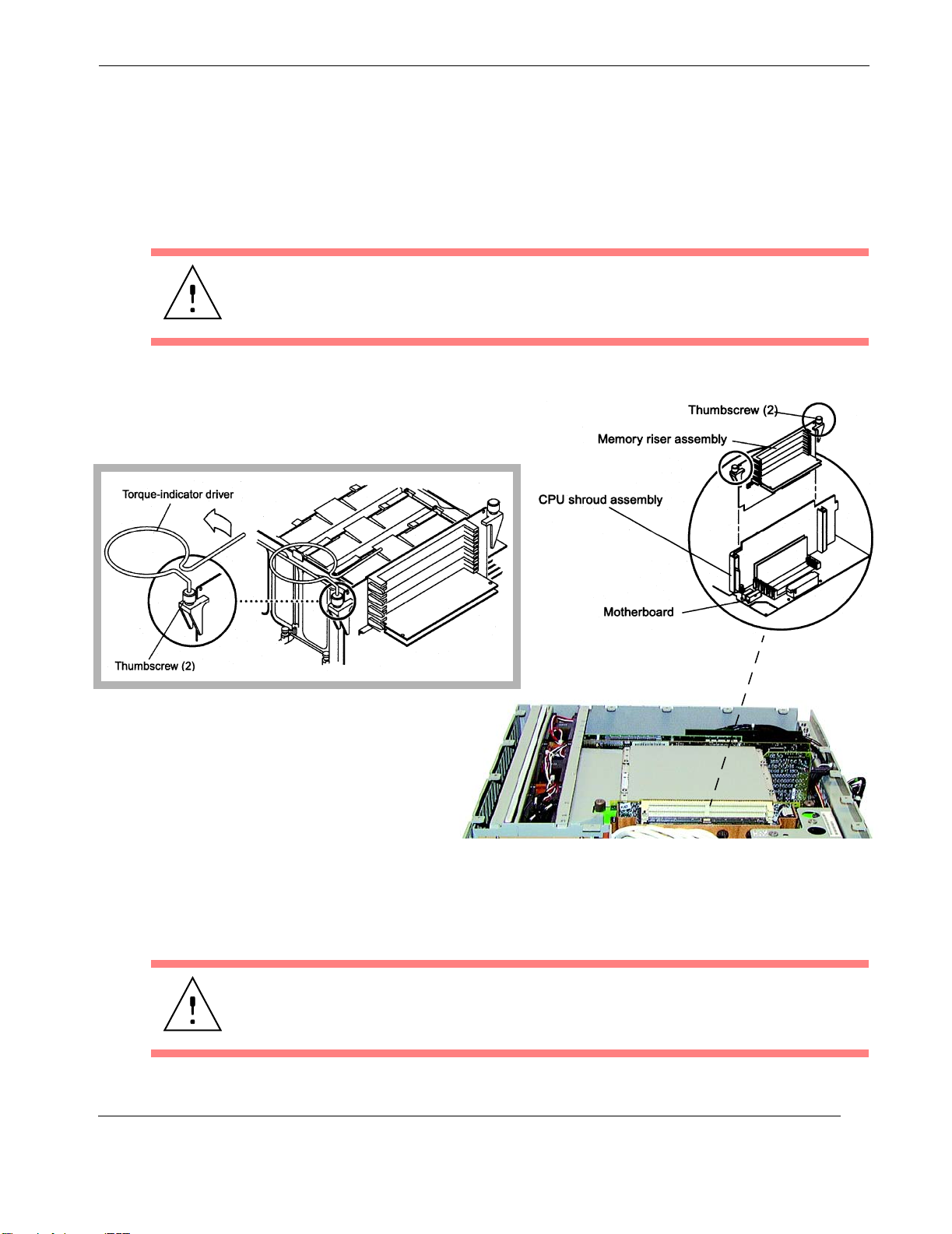
2—Major Assembly Installation
Server Subsystem Assembly
2. Using the short leg of the torque-indicator driver (shipped with the RES-204),
loosen the Riser Assembly thumbscrews by alternately turning each screw
one turn in a counter-clockwise direction (see Figure 2-18 and Figure 2-19 on
page 2-22).
Caution: When removing the Memory Riser Assembly, loosen both of the thumbscrews at the same time to avoid connector damage.
Themis Computer
Figure 2-18. Removing the Memory Riser Assembly
3. Using your hands, loosen the thumbscrews simultaneously until the assembly
is loose.
Caution: The memory riser assembly must come straight out of the Motherboard
connectors to avoid damaging the connectors.
2-21
Page 58
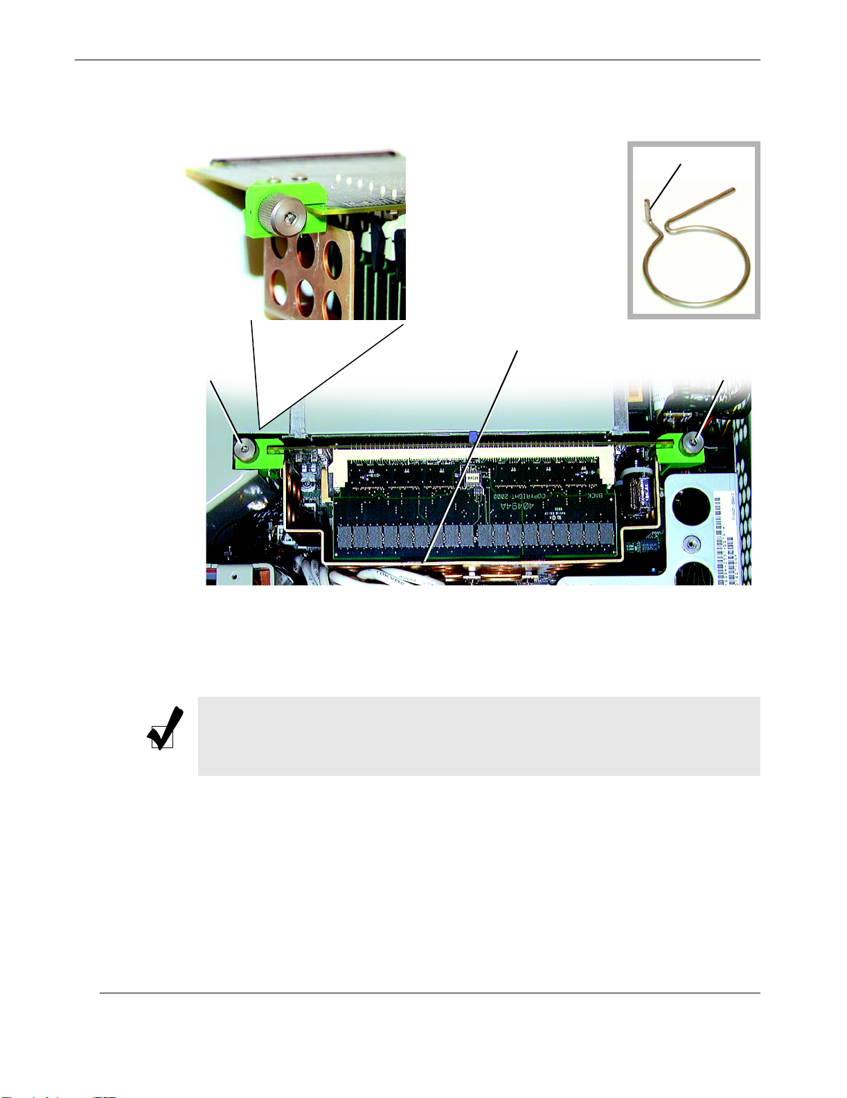
Rugged Enterprise Server 200 Installation Guide
Short leg
Torque
Indicator
Driver
Detailed View
Thumbscrew Thumbscrew
Riser Support Plate
Figure 2-19. Remove the Riser Assembly from the Motherboard
4. When the thumbscrews have reached their full travel path, lift the Memory
Riser Assembly straight up and out of the system.
Note: To give components on the Memory Riser Assembly additional support,
Themis has added a Riser Support Plate to the Assembly. This must be removed
to access the DIMMs on the Riser Assembly.
2-22
5. Remove the eight (8) screws securing the Riser Support Plate to the Assembly
(see Figure 2-20 on page 2-23).
6. Place the Memory Riser Assembly on an antistatic mat.
You may now remove or insert a DIMM on either the Memory Riser Assembly or
the Motherboard surface as necessary (see following sections).
Themis Computer
Page 59
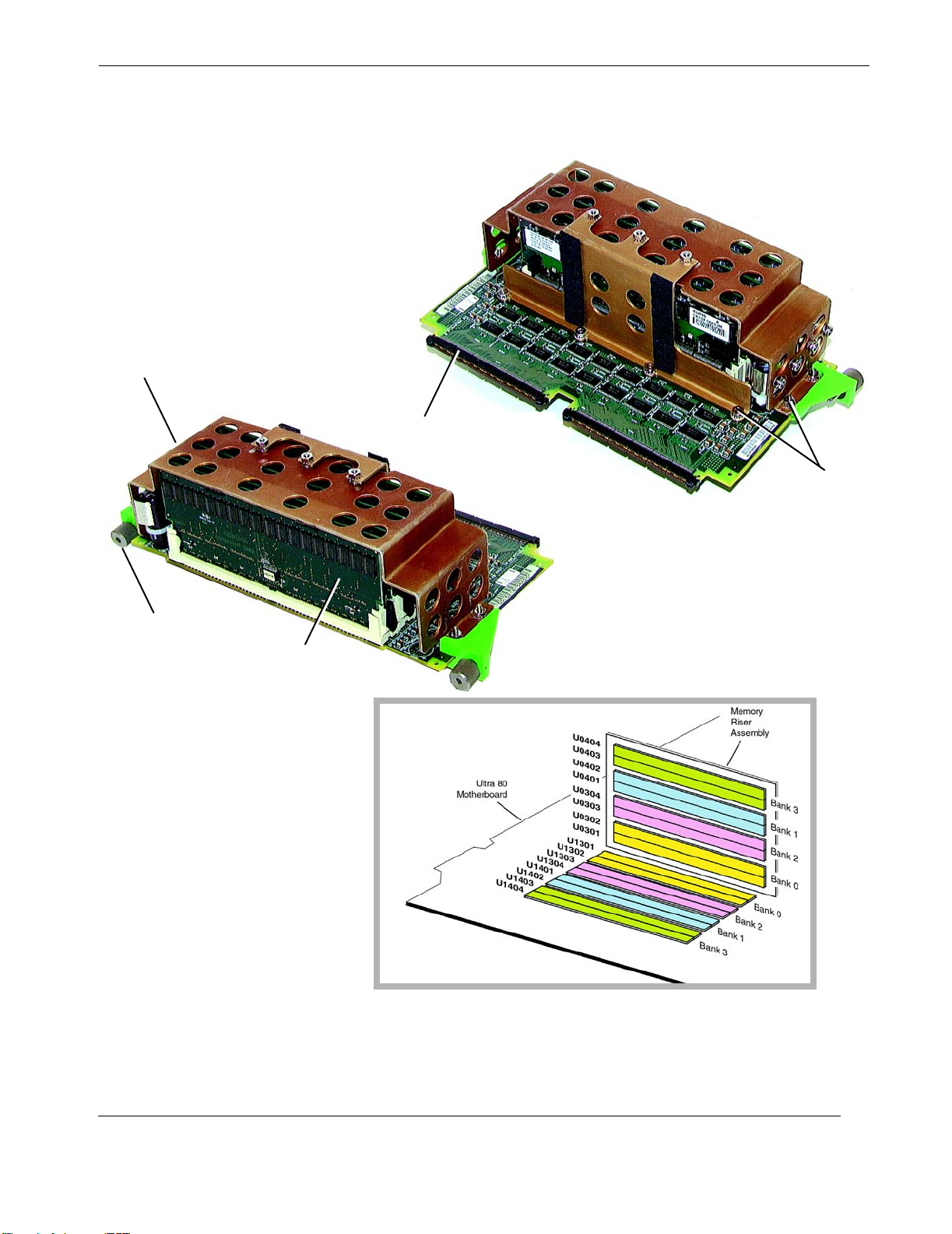
Riser Support Plate
Motherboard connector
AB
2—Major Assembly Installation
Server Subsystem Assembly
Plate screws
(8 total; 2 at each end
4 on one side)
Memory Riser Assembly
Thumbscrew
DIMM (1 of 8)
in Riser Assembly
Figure 2-20. Remove the 8 Screws from the Riser Support Plate (A and B),
then remove DIMM(s) from the Riser Assembly or Motherboard Surface (C)
Motherboard
C
DIMM (1 of 8)
on Motherboard
Themis Computer
2-23
Page 60
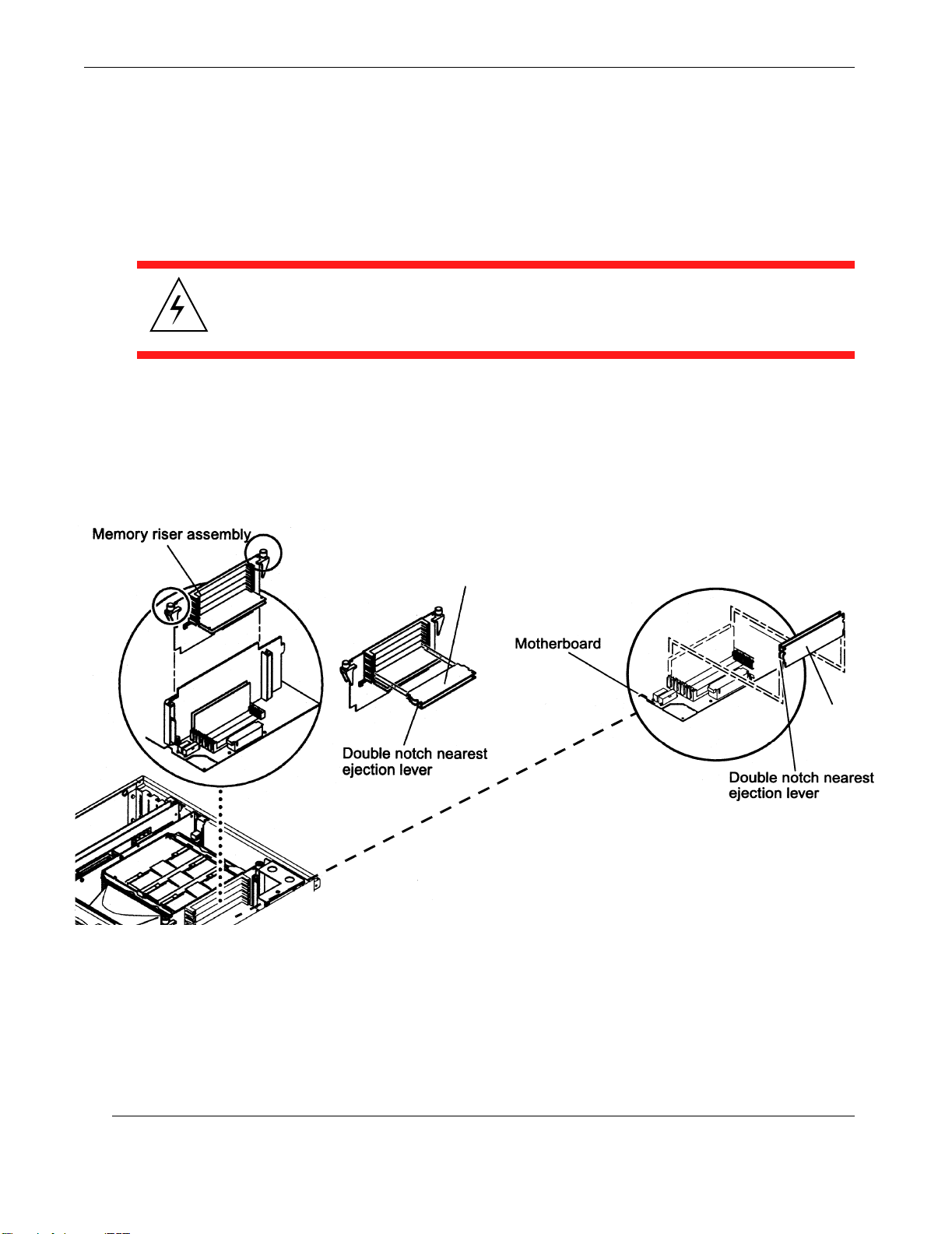
Rugged Enterprise Server 200 Installation Guide
2.1.7.2 Removing a DIMM
1. If you have not already done so, power off the system (see “Powering Off the
System”, page 2-2) and remove the Server Subsystem Assembly (see “Removing the Server Assembly”, page 2-4), including its protective cover plate.
Warnin g : Do not remove any DIMM from its antistatic package until ready to install it in the RES-204. Handle DIMMs only by their edges. Do not touch DIMM
components or metal parts. Always wear a grounding strap when handling DIMMs.
2. Remove the memory riser assembly (see “Removing the Memory Riser Assembly”, page 2-20).
3. Locate the DIMM(s) to be removed on either the Memory Riser Assembly
(see A in Figure 2-21) or the Motherboard (see B in Figure 2-21).
DIMM
B
A
Figure 2-21. Removing and Replacing a DIMM
4. Press down the ejection lever at the end of the DIMM connector.
DIMM
2-24
5. Lift the DIMM straight out of the connector and place it on an antistatic mat.
Themis Computer
Page 61
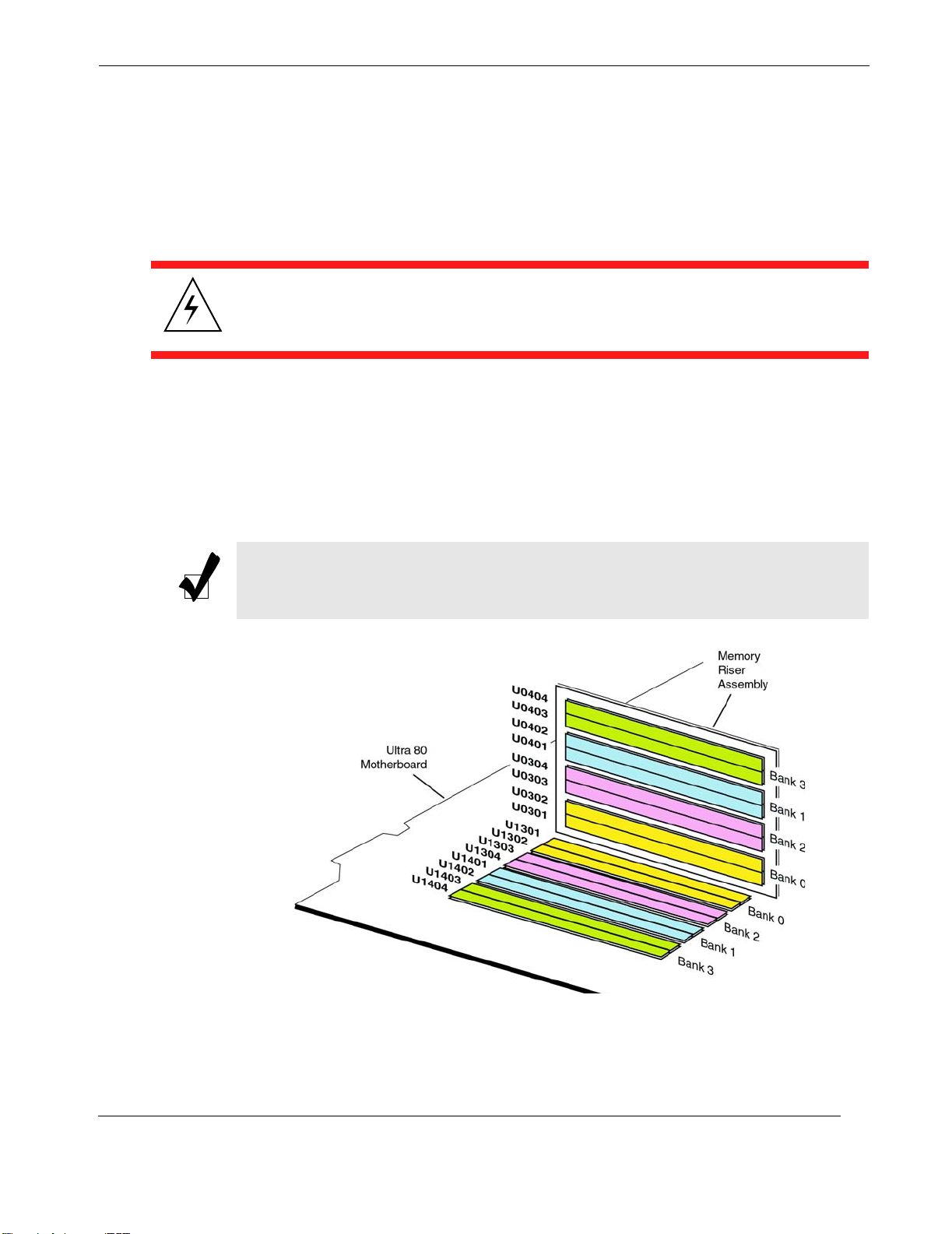
2.1.7.3 Replacing a DIMM
1. If you have not already done so, power off the system (see “Powering Off the
System”, page 2-2) and remove the Server Subsystem Assembly (see “Removing the Server Assembly”, page 2-4), including its protective cover plate.
Warnin g : Do not remove any DIMM from its antistatic package until ready to install it in the RES-204. Handle DIMMs only by their edges. Do not touch DIMM
components or metal parts. Always wear a grounding strap when handling DIMMs.
2. Remove the memory riser assembly (see “Removing the Memory Riser Assembly”, page 2-20).
3. Using Figure 2-22, locate the DIMM(s) to be replaced on either the Memory
Riser Assembly (see A in Figure 2-21, page 2-24) or the Motherboard (see B
in Figure 2-21, page 2-24).
2—Major Assembly Installation
Server Subsystem Assembly
Note: For optimum memory performance, consider interleaving issues when installing DIMMs. See section on “Memory Interleaving”, page 1-8, in Chapter 2.
Figure 2-22. Allocation of DIMMs according to Bank
Themis Computer
2-25
Page 62
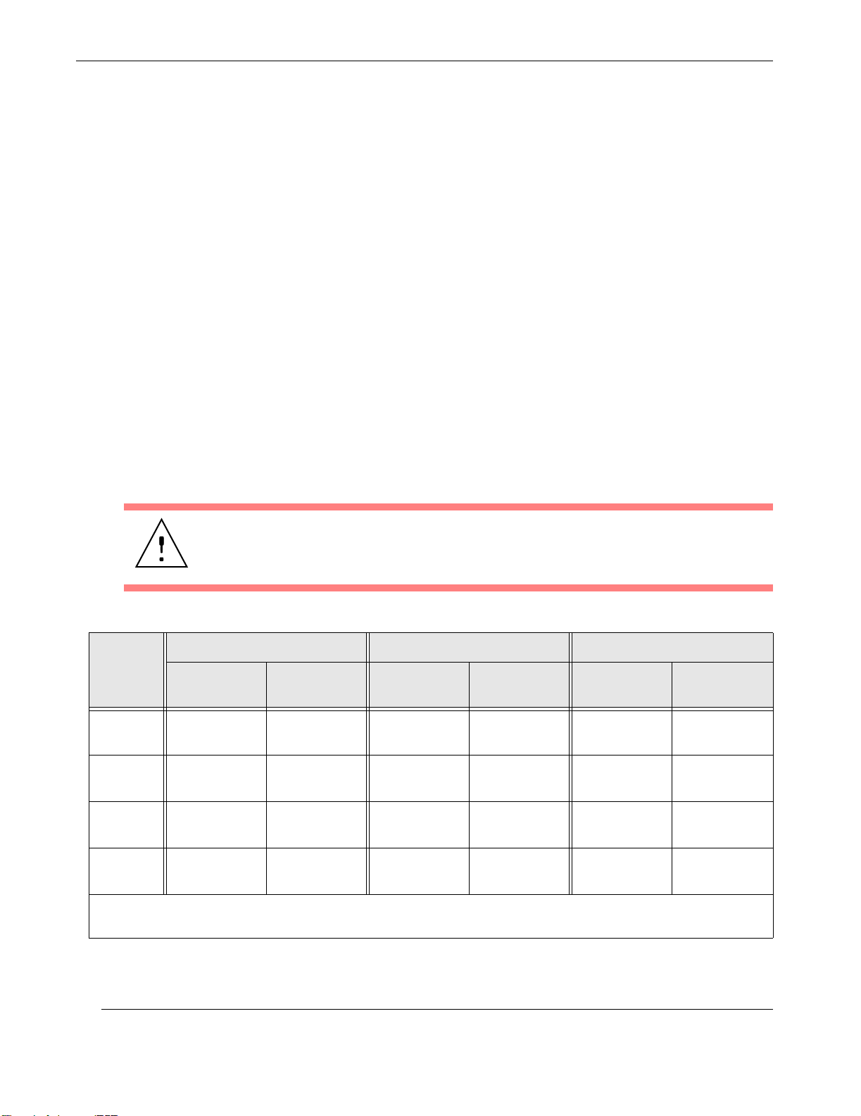
Rugged Enterprise Server 200 Installation Guide
Important: Review the important memory installation information below
before you begin replacing or installing the memory.
DIMMs are arranged in four banks, each bank consisting of four slots. The
four slots in each bank are separated, with two slots on the Motherboard, and
two slots on the memory riser assembly.
Figure 2-22 on page 2-25 shows the placement of the DIMM banks on the
Memory Riser Assembly and the Motherboard. On the Motherboard, bank 3
is closest to the system top, bank 0 is closest to the CPU shroud.
It is important that DIMMs be added to the memory banks according to the
scheme outlined in Table 2-4, page 2-26. Options are a single bank (bank 0;
the default), two-way interleaving (banks 0 and 1, and 4-way interleaving
(banks 0, 1, 2, and 3).
4. Remove the DIMM from the antistatic container.
5. Install the DIMM in a slot connector according to the diagram of Figure 2-22
and the rules of Table 2-4.
Caution: Failure to populate a memory bank with DIMMs of equal capacity will
result in inefficient use of memory resource or system failure.
Table 2-4. DIMM Allocation on the RES-204
For Default: For 2-Way Interleaving: For 4-Way Interleaving:
DIMM**
Bank 0
(default)
Bank 2 None None None None
Bank 1 None None
Bank 3 None None None None
** All 4 slots in a Bank must be filled with DIMMs. Only same-capacity DIMMs may be installed in a Bank (all 128
MB, for example).
Mother-
board Slot
U1301,
U1302
Riser Card
Slot
U0301,
U0302
Mother-
board Slot
U1301,
U1302
U1401,
U1402
Riser Card
Slot
U0301,
U0302
U0401,
U0402
Mother-
board Slot
U1301,
U1302
U1303,
U1304
U1401,
U1402
U1403,
U1404
Riser Card
Slot
U0301,
U0302
U0303,
U0304
U0401,
U0402
U0403,
U0404
2-26
Themis Computer
Page 63
2—Major Assembly Installation
Server Subsystem Assembly
Note: Bank 0 is the default DIMM position for DIMMs installed at the factory.
If DIMMs are being installed rather than being replaced, fill additional DIMM
banks with identical capacity DIMMs in this order: bank 0 and bank 1 (for 2-way
interleaving); or bank 0, bank 1, bank 2, and bank 3 (for 4-way interleaving).
Note: Fill additional DIMM banks in this order: bank 2, bank 1, bank 3. Bank 0
is the default DIMM position for DIMMs installed at the factory.
6. Align the DIMM in the memory slot so that the DIMM's double notch is nearest the memory connector ejection lever.
7. Using your thumbs, press the DIMM straight down into the connector until
the ejection lever clicks, locking the DIMM in the connector.
8. Replace the Memory Riser Assembly after all DIMMs have been installed
(see next section).
2.1.7.4 Replacing the Memory Riser Assembly
Caution: Memory Riser Assembly connectors must be seated straight into the
Motherboard connectors to avoid damaging the Motherboard connector pins.
Replace the memory riser assembly as follows:
1. Replace the eight screws (previously removed) securing the Riser Support
Plate to the Assembly.
2. Position the Memory Riser Assembly on the Motherboard connectors (see
Figure 2-18 on page 2-21).
Caution: Be careful to stay within the internal board guides when inserting the
Memory Riser Assembly. The Assembly will not seat if it is not between the guides.
3. Using your hands, tighten the thumbscrews simultaneously until they are both
finger-tight.
Themis Computer
2-27
Page 64
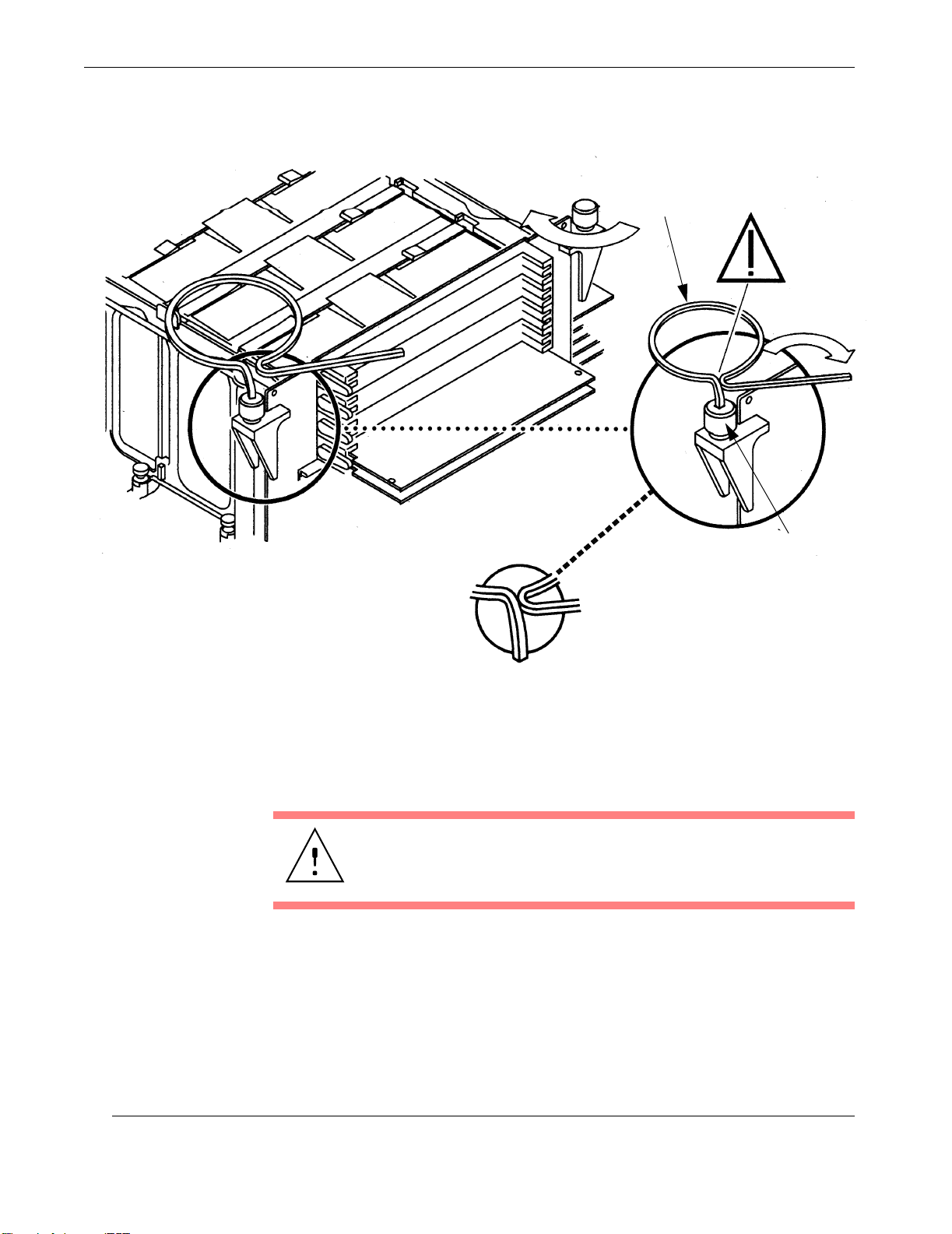
Rugged Enterprise Server 200 Installation Guide
Torque-Indicator
Driver
Thumbscrew
Stop turning thumbscrew
when torque-indicator
driver touches
Figure 2-23. Setting the Memory Riser Assembly Thumbscrew Torque
4. Using the short leg of the torque-indicator driver, alternately turn each thumbscrew clockwise one turn at a time. Stop turning each thumbscrew as soon as
the torque indicator driver gap closes (Figure 2-23)
Caution: Do not apply more torque than needed to close the
torque-indicator drivers's gap. If you apply more torque than
needed to close the gap, you might damage the connectors.
5. Press straight down on the middle of the top of the memory riser assembly to
ensure that it is firmly seated in the Motherboard connector.
2-28
6. Using the torque-indicator driver, alternately turn each thumbscrew clockwise
to ensure that the thumbscrews remained properly torqued after you pressed
downward on the assembly in the previous step.
Themis Computer
Page 65
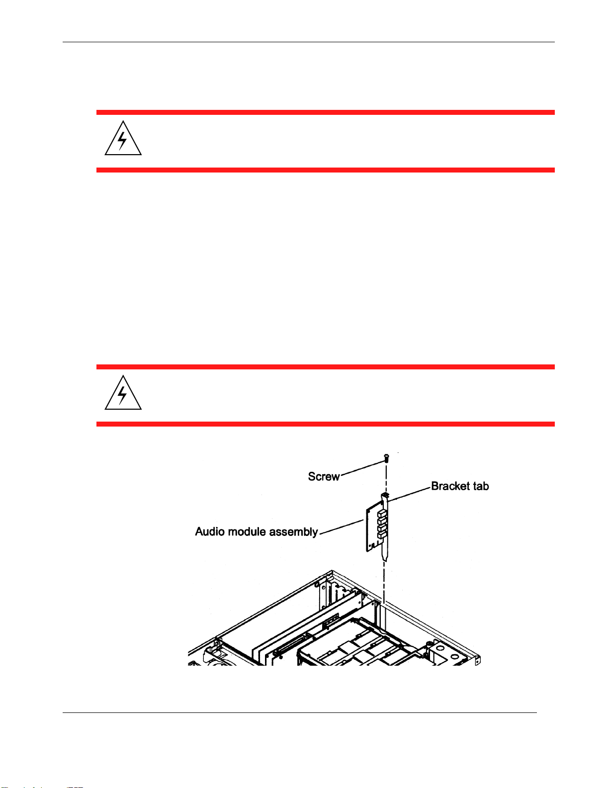
2.1.8 Audio Module Assembly
Warni ng : Use proper ESD grounding techniques when handling components.
Wear an antistatic wrist strap and use an ESD-protected mat. Store ESD-sensitive
components in antistatic bags before placing them on any surface.
Use the following procedures to remove and replace the audio module assembly.
2.1.8.1 Removing the Audio Module Assembly
1. Power off the system (see “Powering Off the System”, page 2-2) and remove
the Server Subsystem Assembly (see “Removing the Server Assembly”, page
2-4), including its protective cover plate.
2. Disconnect any external audio cables from the Audio Module Assembly.
2—Major Assembly Installation
Server Subsystem Assembly
3. Using a No. 2 Phillips screwdriver, remove the screw securing the Audio
Module Assembly bracket tab to the system chassis (see Figure 2-24).
Warnin g : Avoid damaging the connector by not applying force to one end or one
side of the module.
Themis Computer
Figure 2-24. Removing and Replacing the Audio Module Assembly
2-29
Page 66

Rugged Enterprise Server 200 Installation Guide
4. At the two upper corners of the audio module assembly, pull the module
straight up from the slot.
5. Remove the audio module assembly.
6. Place the audio module assembly on an antistatic mat.
2.1.8.2 Replacing the Audio Module Assembly
1. If you have not already done so, power off the system (see “Powering Off the
System”, page 2-2) and remove the Server Subsystem Assembly (see “Removing the Server Assembly”, page 2-4), including its protective cover plate.
2. Position the Audio Module Assembly into the chassis.
3. Lower the audio module assembly connector so that it touches its associated
card slot J3701 on the Motherboard (see Figure 2-2 on page 2-3).
4. Align the Audio Module Assembly bracket tab with the chassis back panel
cutout.
5. At the two upper corners of the module, push the module straight down into
slot J3701 until the module is fully seated.
6. Using a No. 2 Phillips screwdriver, replace the screw previously removed and
secure the Audio Module Assembly to the system chassis.
7. Connect any external audio cables to the Audio Module.
2-30
Themis Computer
Page 67
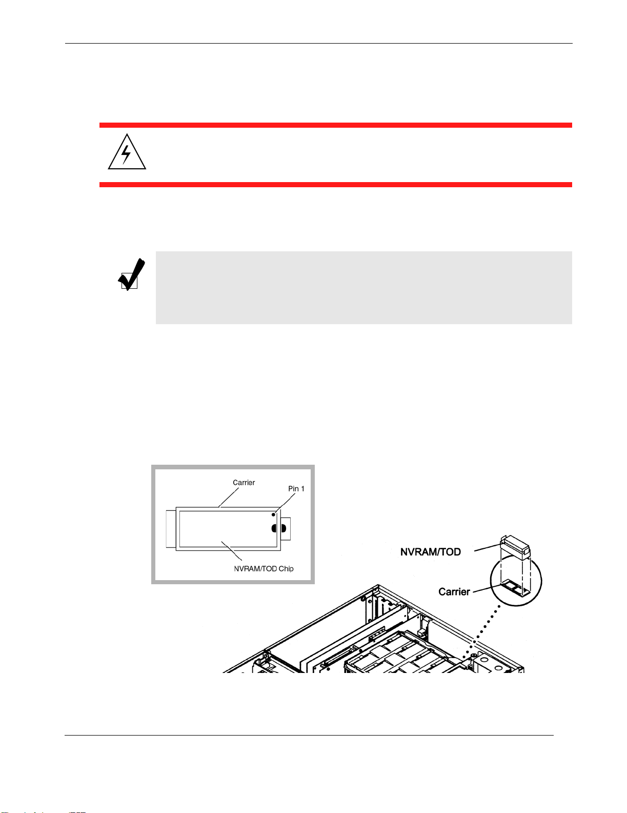
2.1.9 NVRAM/TOD Assembly
Warni ng : Use proper ESD grounding techniques when handling components.
Wear an antistatic wrist strap and use an ESD-protected mat. Store ESD-sensitive
components in antistatic bags before placing them on any surface.
The NVRAM/TOD Assembly consists of the 28-pin NVRAM/TOD chip and its carrier. Use the following procedure to remove and replace the NVRAM/TOD chip.
Note: The NVRAM/TOD contains the system host identification (ID) and Ethernet address. If the same ID and Ethernet address are to be used, consult your authorized Themis sales representative to confirm a NVRAM/TOD part number
prior to replacement.
2—Major Assembly Installation
Server Subsystem Assembly
2.1.9.1 Removing the NVRAM/TOD Assembly
1. Power off the system (see “Powering Off the System”, page 2-2) and remove
the Server Subsystem Assembly (see “Removing the Server Assembly”, page
2-4), including its protective cover plate.
2. Locate the NVRAM/TOD and its carrier on the Motherboard (see Figure 2-2,
page 2-3, and Figure 2-25).
Themis Computer
Figure 2-25. Locate and Remove the NVRAM/TOD carrier
2-31
Page 68
Rugged Enterprise Server 200 Installation Guide
3. Grasp the NVRAM/TOD carrier at each end and pull straight up. It is OK to
gently wiggle the carrier as necessary.
4. Place the removed NVRAM/TOD and carrier on an antistatic mat.
2.1.9.2 Replacing the NVRAM/TOD Assembly
1. Power off the system (see “Powering Off the System”, page 2-2) and remove
the Server Subsystem Assembly (see “Removing the Server Assembly”, page
2-4), including its protective cover plate.
2. Position the NVRAM/TOD and carrier on the Motherboard after aligning the
carrier key.
Caution: The NVRAM/TOD chip is marked with a half-circle at one end and a
small circle to indicate pin 1. When re-inserting the chip into its carrier, make sure
the half-circle end is inserted into the end of the carrier with a matching half-circle.
The carrier itself is keyed at the bottom, hence can only be inserted one way into its
socket on the Motherboard.
3. Carefully insert the NVRAM/TOD/carrier into the socket.
4. Firmly push the NVRAM/TOD Assembly until properly seated.
2-32
Themis Computer
Page 69
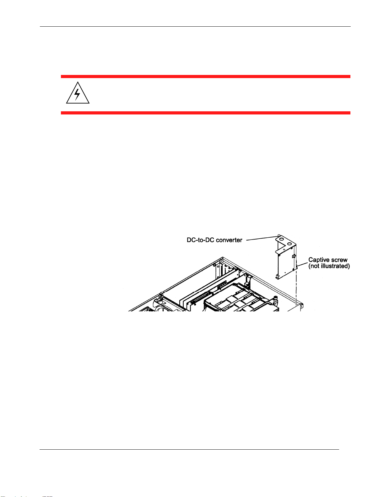
2.1.10 DC-to-DC Converter Assembly
Warni ng : Use proper ESD grounding techniques when handling components.
Wear an antistatic wrist strap and use an ESD-protected mat. Store ESD-sensitive
components in antistatic bags before placing them on any surface.
Use the following procedure to remove and replace the DC-to-DC Converter Assembly.
2.1.10.1 Removing the DC-to-DC Converter Assembly
1. Power off the system (see “Powering Off the System”, page 2-2) and remove
the Server Subsystem Assembly (see “Removing the Server Assembly”, page
2-4), including its protective cover plate.
2—Major Assembly Installation
Server Subsystem Assembly
2. Locate the DC-to-DC Converter Assembly on the Motherboard (see Figure
2-2, page 2-3, and Figure 2-26).
Figure 2-26. Locate and Remove the DC-to-DC Converter
3. Remove the DC-to-DC Converter Assembly as follows:
a. Using a long-shaft No. 2 Phillips screwdriver, loosen the captive screw se-
curing the DC-to-DC Converter Assembly to the Motherboard.
b. Using the two holes in the metal shroud as a grip, lift the Converter
straight up. This will automatically disconnect the Converter from connectors J4105 and J4108 on the Motherboard.
Themis Computer
c. Remove the Converter from the chassis.
2-33
Page 70

Rugged Enterprise Server 200 Installation Guide
2.1.10.2 Replacing the DC-To-DC Converter Assembly
Replace the DC-to-DC Converter Assembly as follows:
1. Position the DC-to-DC Converter Assembly connectors over the Motherboard connectors J4105 and J4108.
2. Using a No. 2 Phillips screwdriver, tighten the captive screw securing the DCto-DC converter assembly to the Motherboard.
2-34
Themis Computer
Page 71
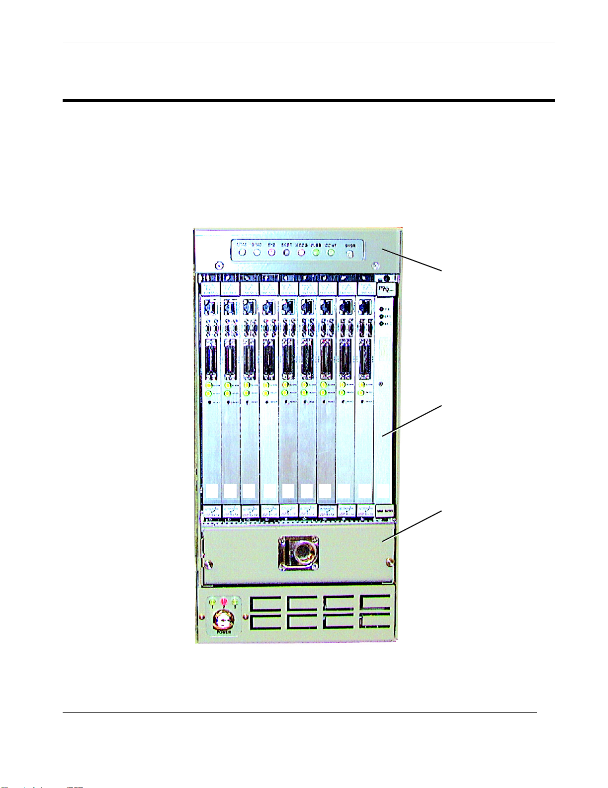
2.2 VME I/O Boards
The RES-204 VME I/O Subsystem can support up to 10 VME I/O boards (see Figure 2-27. The only requirement is that the VME Buffer/Alarm Board be installed in
slot 1 to communicate with the Server Subsystem Ultra 80 Motherboard, and to
VME
act as the system controller for any other VME boards that may be installed.
2—Major Assembly Installation
System I/O Panel
SLOT:
1
234 5678910
Figure 2-27.
VME I/O Board (10 total)
VME I/O Fan Tray
The VME I/O Subsystem
Themis Computer
2-35
Page 72

Rugged Enterprise Server 200 Installation Guide
Use the following procedure to remove or replace a VME board.
2.2.1 Removing a VME Board
1. Disconnect any external cables connected to the VME board.
2. Unscrew the top and bottom screws holding the VME board to the RES-204.
3. Carefully pull the VME board from its RES-204 cabinet slot.
4. Place the VME board on an antistatic mat.
2.2.2 Replacing a VME Board
1. Carefully place the VME board into its RES-204 chassis slot.
2. Push the VME board until it rear connector seats with the VME backplane.
When properly seated, the VME board’s front panel will be flush with the
RES-204 cabinet.
3. Secure the top and bottom screws of the VME board to the cabinet.
4. Reconnect external cables with the VME board.
2-36
Themis Computer
Page 73
2.3 Hard-Disk Drives
Warni ng : Use proper ESD grounding techniques when handling components.
Wear an antistatic wrist strap and use an ESD-protected mat. Store ESD-sensitive
components in antistatic bags before placing them on any surface.
The RES-204 can support up to three hard-disk drives, all contained in a disk-drive
tray; one drive is mandatory for booting the Solaris operating system. The disk-drive
tray is located within the right side of the Server Subsystem Assembly (see section
“Server Subsystem Assembly”, page 2-1). To remove a disk drive, however, the
Server Subsystem Assembly does not have to be removed from the RES-204 chassis. Use the following procedure to remove and replace a disk drive.
2—Major Assembly Installation
2.3.1 Removing a Hard-Disk Drive
1. Power off the system (see “Powering Off the System”, page 2-2).
2. Release the four Phillips-head screws that hold the disk-tray dust cover to the
Server Subsystem Assembly; remove the cover (see Figure 2-4 on page 2-5).
3. Reach into the small U-shaped depression in the disk-drive Latch Lock and
push down (see Figure 2-28). This will cause the Drive Latch to release and
swing away from the disk drive.
4. Pull the Drive Latch forward until the disk drive has cleared the chassis.
Caution: When pulling the disk drive from the RES-204 chassis, hold it at the bottom to prevent it from falling and damaging the drive.
2.3.2 Replacing a Hard-Disk Drive
1. If you have not already so, power off the system (see “Powering Off the System”, page 2-2).
Themis Computer
2. Carefully insert the disk drive into one of the empty drive slots and push its
Drive Latch until the drive has mated with its connector at the back of the slot.
Before the drive has fully mated with its connector, the Drive Latch will
2-37
Page 74
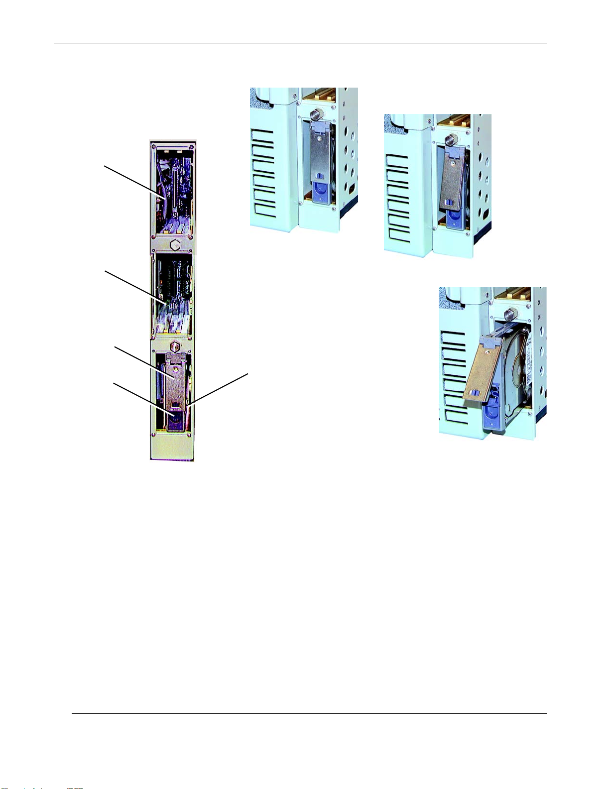
Rugged Enterprise Server 200 Installation Guide
Hard-Disk
Drive slot
A
Hard-Disk
Drive slot
Drive Latch
Latch Lock
Locate the drive, ...
Hard-Disk
Drive
[1 boot drive
is mandatory]
B
push down the Latch Lock, ...
C
Disk Tray
Figure 2-28.
Replacing the RES-204 Hard-Disk Drives
and pull drive out
swing forward as a result of coming into contact with the RES-204 chassis.
Further pushing will engage the Latch Lock, which will lock the drive into
place.
2-38
3. After all disk drives have been installed, fasten the four Phillips-head screws
to secure the disk-tray dust cover to the Server Subsystem Assembly (see Figure 2-4 on page 2-5).
Themis Computer
Page 75
2.4 CD-ROM Drive
Warni ng : Use proper ESD grounding techniques when handling components.
Wear an antistatic wrist strap and use an ESD-protected mat. Store ESD-sensitive
components in antistatic bags before placing them on any surface.
The RES-204 contains one CD-ROM drive that is shock-mounted to prevent signal
interruption in case the cabinet is suddenly jarred. Use the following procedure to
remove and replace a disk drive.
2.4.1 Removing a CD-ROM Drive
1. If you have not already done so, power off the system (see “Powering Off the
System”, page 2-2) and remove the Server Subsystem Assembly (see “Removing the Server Assembly”, page 2-4), including its protective cover plate.
2—Major Assembly Installation
2. Release the Phillips-head mounting screws that hold the CD-ROM to the
Server Subsystem Assembly (see Figure 2-29 on page 2-40).
3. Disconnect the single cable (combined power and data) to the CD-ROM.
4. Remove the CD-ROM.
2.4.2 Replacing a CD-ROM Drive
5. Reconnect the single cable (combined power and data) to the CD-ROM.
6. Position the CD-ROM drive within the Server Subsystem Assembly so that
the mounting screw holes are aligned (see Figure 2-29 on page 2-40).
7. Insert and tighten all Phillips-head mounting screws previously removed.
Themis Computer
2-39
Page 76
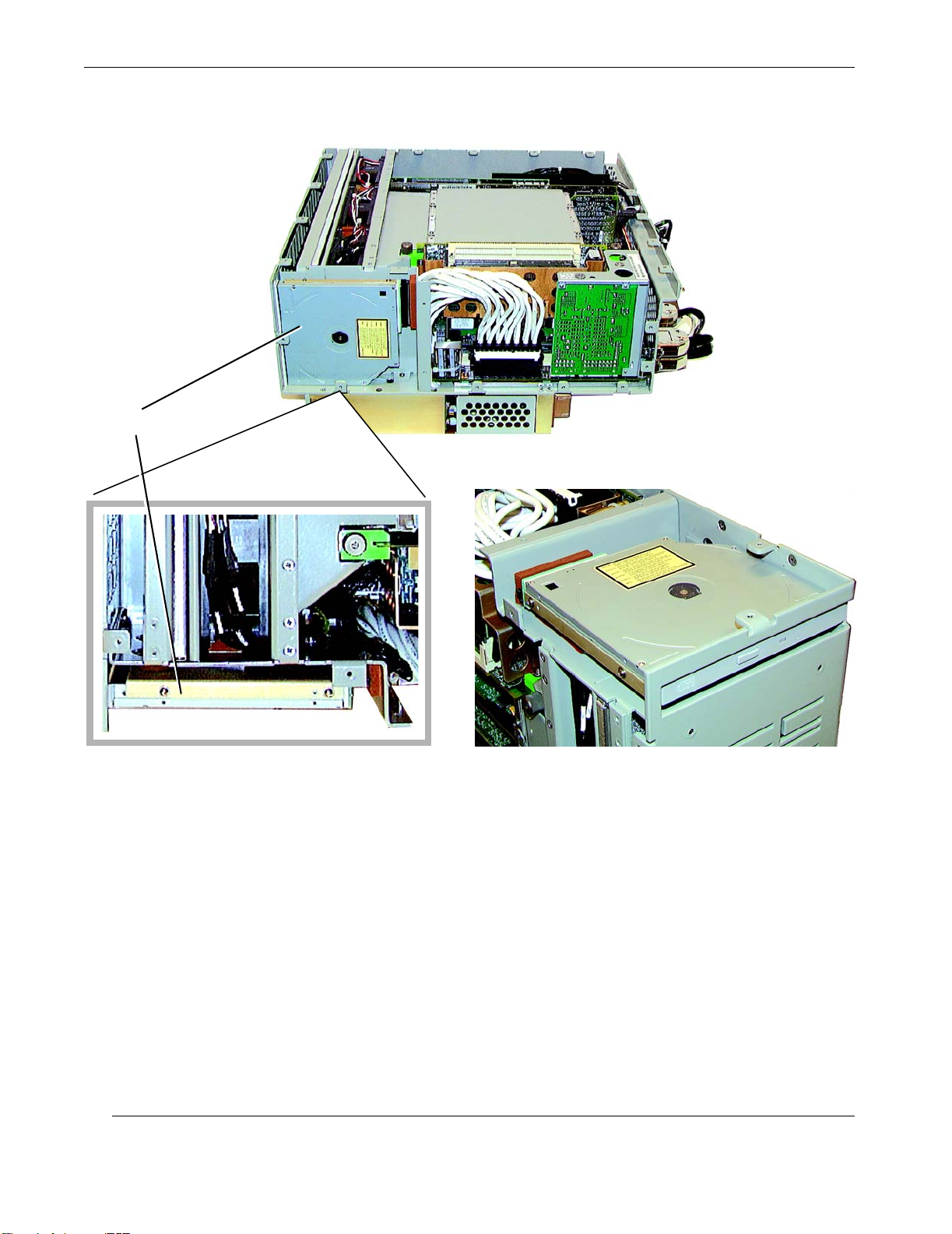
Rugged Enterprise Server 200 Installation Guide
CD-ROM Drive
A
Detailed Top View
Figure 2-29. Location of the RES-204 CD-ROM Drive
B
2-40
Themis Computer
Page 77
2.5 Power Supplies
The RES-204 can support up to three power supplies, which are at the rear of the
cabinet (see Figure 1-4, page 1-4). One power supply is sufficient to power a basic
system with one CPU Module installed. As a rule,
power a system with two CPU Modules, and
three or more CPU Modules.
Each power supply has an LED associated with it that describes its operational status
(details are described in Chapter 4, "Managing Your System", in the section “Power
Supply Status LEDs”, page 4-2). The power-supply status LEDs are on the front of
the RES-204 above the power key-switch.
Use the following procedure to remove and replace a power supply.
2—Major Assembly Installation
two power supplies are required to
three power supplies for a system with
Warni ng : Use proper ESD grounding techniques when handling components.
Wear an antistatic wrist strap and use an ESD-protected mat. Store ESD-sensitive
components in antistatic bags before placing them on any surface.
2.5.1 Removing a Power Supply
1. If you have not already so, power off the system (see “Powering Off the System”, page 2-2)
2. Unlatch the at the top of the power supply (see Figure 1-4, page 1-4).
3. Using the latch, pull the power supply away from the cabinet.
Caution: When pulling the power supply from the RES-204 chassis, hold it at the
bottom to prevent it from falling and damaging the unit.
2.5.2 Replacing a Power Supply
Themis Computer
1. If you have not already so, power off the system (see “Powering Off the System”, page 2-2).
2-41
Page 78
Rugged Enterprise Server 200 Installation Guide
2. Carefully insert the power supply into an empty slot and push it until it has
mated with its connector at the backplane.
3. Refasten the latch at the top of the power supply.
Note: When the system is turned on, a green Status LED on the front of the RES-
204 above the key-switch will indicate that the corresponding power supply is fully operational.
2-42
Themis Computer
Page 79
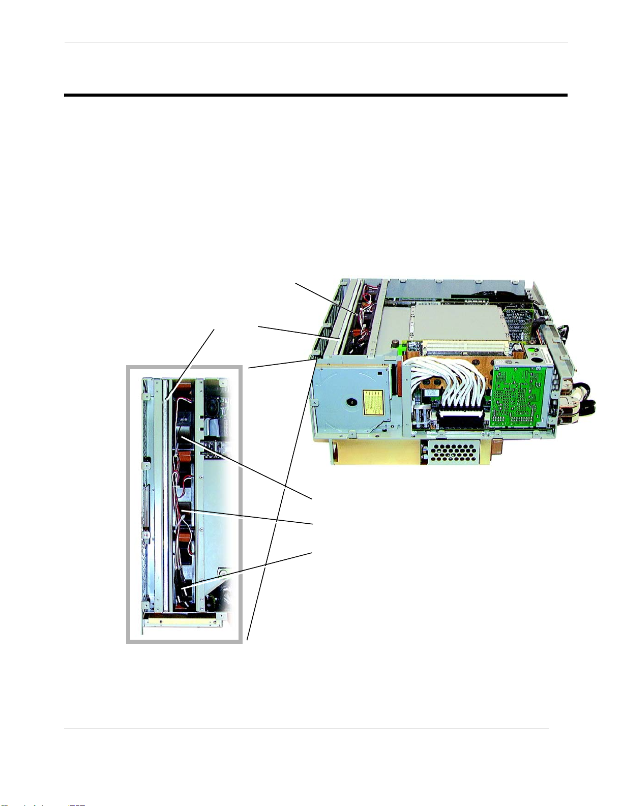
2.6 Server Assembly Fans
There are three 120-mm Server Assembly fans in the RES-204, each of which has a
separate 3-wire harness cable for power and control (see Figure 2-30). All of the
fans must be removed from the system in order to replace any one of them. Use the
following procedure to remove and replace a Server fan.
[A more detailed description of the Server fans is provided in the section “Cooling
System Monitoring and Control”, page 4-4, in Chapter 4, "Managing Your System".]
Fan Slots
Server Fan Filter
2—Major Assembly Installation
Server Assembly Fans
Themis Computer
Fan 3
Fan 2
Fan 1
Detailed Top View
Figure 2-30. Location of the RES-204 Server Fans
2-43
Page 80
Rugged Enterprise Server 200 Installation Guide
Warni ng : Use proper ESD grounding techniques when handling components.
Wear an antistatic wrist strap and use an ESD-protected mat. Store ESD-sensitive
components in antistatic bags before placing them on any surface.
2.6.1 Removing the Server Fans
1. If you have not already so, power off the system (see “Powering Off the System”, page 2-2) and remove the Server Subsystem Assembly (see “Removing
the Server Assembly”, page 2-4), including its protective cover plate.
2. Start by pulling Fan 3 from its fan slot. Prying up the outside corner makes it
easier. [Each fan is held in place by friction fit.]
3. Lay Fan 3 on its side and begin pulling Fan 2 from its fan slot.
4. Lay Fan 2 on its side and pull Fan 1 from its slot.
5. Cut the tie-wraps used to bundle all three sets of fan leads together.
6. Disconnect the 3-wire lead connector from the faulty fan. If more than one fan
is being removed, carefully note which fan is connected to each connector.
2-44
Themis Computer
Page 81
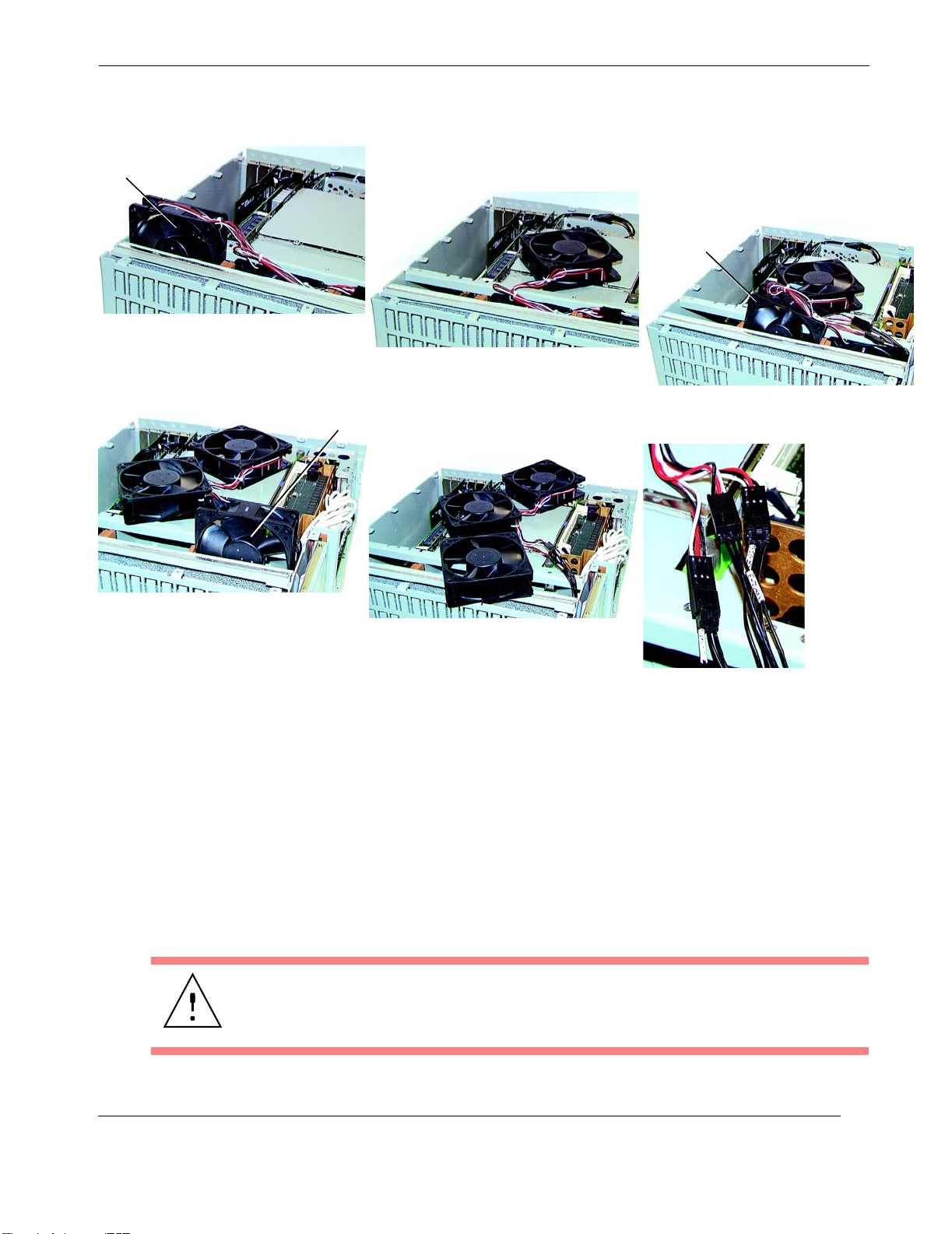
Fan 3
Pull Fan 3 from its slot, . . .
2—Major Assembly Installation
Server Assembly Fans
Fan 2
lay it on its side, . . .
Fan 1
followed by Fan 1, . . .
until all fans are removed.
Figure 2-31.
Remove Each Server Fan, Starting with Fan 3
2.6.2 Replacing the Server Fans
1. Reconnect the removed fan-lead connector to its counterpart on the RES-204
chassis.
then pull Fan 2 from its slot, . . .
Disconnect all fan leads.
Themis Computer
2. After all fan leads are connected, reinstall each fan starting with Fan 1, then
Fan 2, and finally Fan 3 (reverse the procedure of Figure 2-31). Make sure
each fan is seated in its slot by pushing firmly on the top of the fan.
Caution: Improper seating of any of the three Server fans will cause reduced air
flow to the Server Assembly and its CPU Modules, resulting in excessive heat and
a resulting shutdown.
2-45
Page 82
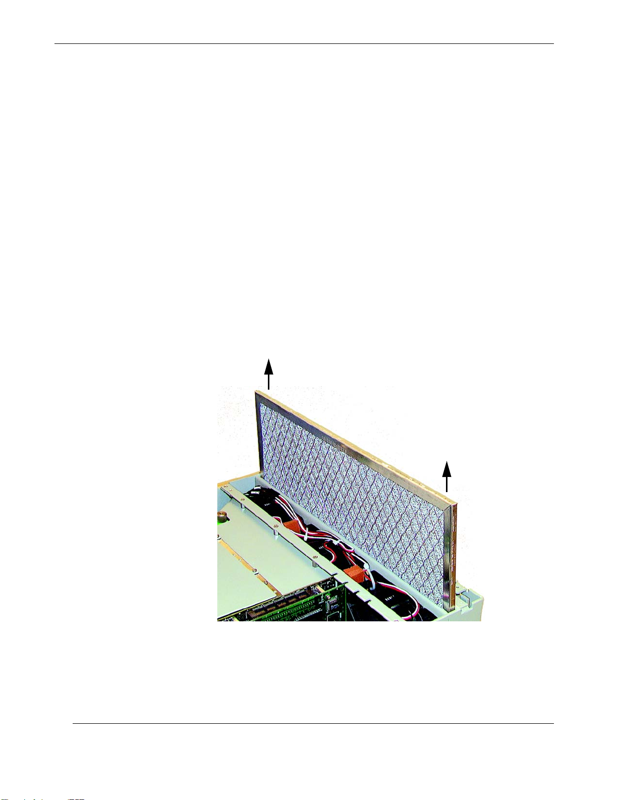
Rugged Enterprise Server 200 Installation Guide
2.6.3 Removing and Replacing the Server Fan Filter
Improper cooling of the Server Assembly when all three fans are working optimally
may be the result of a dirty Server Fan Filter. Use the following procedure to remove
and replace this Filter.
1. If you have not already so, power off the system (see “Powering Off the System”, page 2-2) and remove the Server Subsystem Assembly (see “Removing
the Server Assembly”, page 2-4), including its protective cover plate.
2. Begin carefully prying out the corners at each end of the Server Fan Filter. The
Filter is held in place by friction fit (see Figure 2-32 on page 2-46).
Important: Within the first inch of travel upwards, the Filter may have to be
pushed slightly toward the rear to allow its bottom edge to clear a retaining
flange at the bottom of the Filter slot.
3. When the Fan Filter is removed, wash it gently in mild soapy water and let it
dry in open air.
2-46
Figure 2-32. Remove the Server Fan Filter by Pulling Evenly at Both Corners
Themis Computer
Page 83
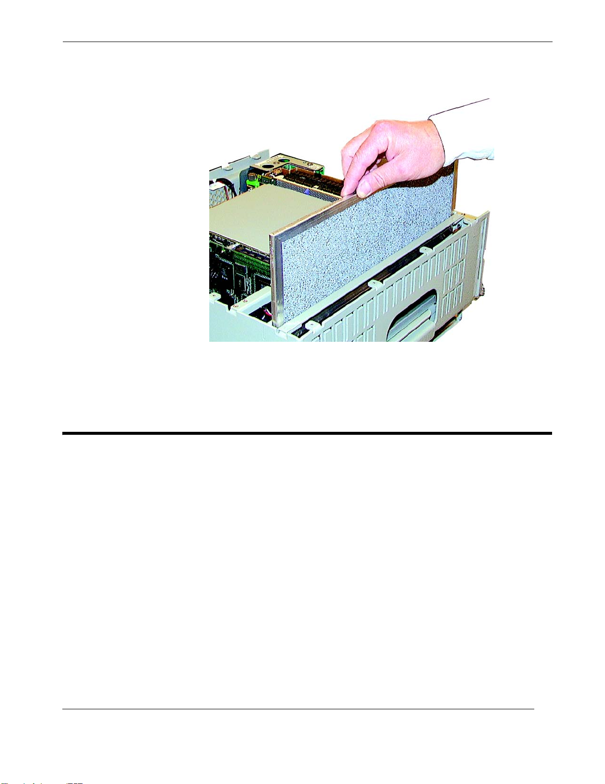
2—Major Assembly Installation
VME I/O Fan Tray
Figure 2-33.
Replace the Server Fan Filter by Inserting Evenly into the Slot
4. After the Fan Filter is completely dry, return it to its slot and push down equally at both corners (see Figure 2-33 on page 2-47) until firmly seated.
2.7 VME I/O Fan Tray
Fail of one or more of the four fans in the VME I/O Fan Tray requires replacement of
the complete Fan Tray.
[A more detailed description of the VME I/O Fan Tray is provided in the section
“Cooling System Monitoring and Control”, page 4-4, in Chapter 4, "Managing Your
System".]
Use the following procedure to remove and replace the VME Fan Tray.
1. Before starting, a spare VME Fan Tray must be available for installation.
[Call your authorized Themis representative to place an order.]
2. Unfasten the two captive thumbscrews at the front of the VME Fan Tray (see
Figure 2-34).
Themis Computer
2-47
Page 84
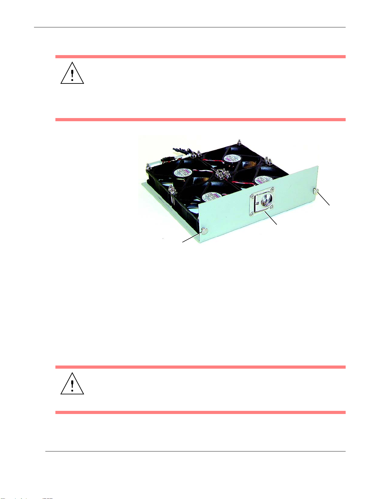
Rugged Enterprise Server 200 Installation Guide
Caution: The VME I/O Subsystem does not have to be shut down during replacement of the VME I/O Fan Tray if the procedure is performed quickly (in minutes).
During Fan Tray removal, however, the VTAC status LED on the Front Panel display
of the RES-204 will turn red.
If longer time is required, however, system alarms will detect the loss of cooling and
begin to shut the RES-204 down.
Thumbscrew
Handle
Thumbscrew
Figure 2-34. The VME I/O Fan Tray
3. Pull the Fan Tray from the RES-204 chassis by pulling on its handle. The Fan
Tray will automatically disconnect from its backplane connector, removing
both power and control capability.
4. Immediately insert the spare Fan Tray into the chassis, push until the rear connector engages its backplane counterpart, and tighten the two thumbscrews.
The VTAC status LED on the RES-204 Front Panel should turn green. If the
LED remains red, the Fan Tray may not be seated properly, may be defective, or there may be a problem with the alarm circuitry.
Caution: If the VTAC status LED stays red after you have determined that the Fan
Tray has been correctly installed, the system will have to be shut down until the
problem has been corrected. Call your authorized Themis representative or Themis
Customer Service for assistance.
2-48
Themis Computer
Page 85

Operation
Section
This chapter describes details of your system configuration that can be used to optimize and balance CPU processing speed with I/O throughput across all components
of the RES-204.
3.1 Introduction
Because of the great diversity in CPU processing and I/O data-handling capacity of
the RES-204, different components of the system may contribute to an overall system slowdown—and even actual stoppage—because of the conflicting way in which
they are configured. The extent of these conflicting configurations can be devastating to system performance, and cause CPU processing time to be unknowingly
wasted on unnecessary overhead rather than data-handling and signal-routing expediency.
Chapter
3
Configuring Your System
Themis Computer
This chapter is designed to capture the details of your system by listing the initialization and operational parameters of each major component (Server CPU & I/O, and
VME I/O boards). By carefully filling out the tables that follow, a more complete
picture of your system operation can be presented. This, in turn, can be extremely
helpful in quickly analyzing any problems in performance that you may be experiencing.
Note: Themis Computer strongly recommends that the information requested in
the tables of this chapter be completed so that, when you call to report a particular
problem, experienced technicians and engineers can arrive at a quick diagnosis
and successful solution.
3-1
Page 86

Rugged Enterprise Server 200 Installation Guide
3.2 Server Configuration
3.2.1 RES-204 Server Checklist
To record the configuration of the Server subsystem of your Rugged Enterprise
Server 200, please fill out Table 3-1, "RES-204 Server Configuration" on the follow-
ing fold-out page as accurately as you can.
If you require help entering particular details, call your Themis Computer distributor
directly or Themis Customer Service at (510) 252-0870.
3.3 VME I/O Configuration
3.3.1 RES-204 VME I/O Checklist
To record the configuration of the VME I/O subsystem of your RES-204, please fill
out Table 3-2, "RES-204 VME-I/O Configuration—Arbitration/Address Mapping",
and Table 3-3, "RES-204 VME-I/O Configuration—Master and Slave Access
Modes", on the following fold-out pages as accurately as you can.
If you require help entering particular details, call your Themis Computer distributor
directly or Themis Customer Service at (510) 252-0870.
3-2
Themis Computer
Page 87

3
3–Configuring Your System
Table information is for a RES-204
Ultra 80 Motherboard
.
Ultra 80
Motherboard
CPU
Slot 2* Yes Yes Yes Yes
Bank 0
(default)
DIMM**
Bank 2 None None None None U1303, U1304 U0303, U0304
Bank 1 None None U1401, U1402 U0401, U0402 U1401, U1402 U0401, U0402
Bank 3 None None None None U1403, U1404 U0403, U0404
How Many CPU Modules
are Installed?
1 2 3 4 Motherboard Slot Riser Card Slot Motherboard Slot Riser Card Slot Motherboard Slot Riser Card Slot
Slot 0
Slot 1
Slot 3
Table 3-1. RES-204 Server Configuration
How Much Memory is Installed?
For Default: For 2-Way Interleaving: For 4-Way Interleaving:
U1301, U1302 U0301, U0302 U1301, U1302 U0301, U0302 U1301, U1302 U0301, U0302
DIMM Memory
Performance Parameters Description of Boards Installed on Ultra 80 Motherboard
Slot 1 33 MHz, 32- or 64-bit bus width, 5-volt interface
PCI
Card
Slot 2 33 MHz, 32- or 64-bit bus width, 5-volt interface
Slot 3 33 or 66 MHz, 32- or 64-bit bus width, 3.3-volt interface l PCI I/O Card (with Themis VME-Bridge circuitry) - Required
Slot 4 33 MHz, 32-bit bus width, 5-volt interface
UPA
Card
*A CPU Module must be installed in slot 2.
**All 4 slots in a Bank must be filled with DIMMs. Only same-capacity DIMMs may be installed in a Bank (all 128 MB, for example).
PCI I/O Card
Slot 1 120 MHz, 64-bit UPA bus width
Slot 2 120 MHz, 64-bit UPA bus width
Graphics I/O (UPA) Card
Themis Computer
Creator3DQuad FastEthernet NIC Elite3D m3/m6
3-3
Page 88

Rugged Enterprise Server 200 Installation Guide
3-4
Themis Computer
Page 89

3–Configuring Your System
Table 3-2. RES-204 VME-I/O Configuration—Arbitration/Address Mapping
VME
Slot
1
Type and/or Description
of VME Board Installed
VME Buffer/Alarm Board
- Required
2 No
3 No
4 No
5 No
6 No
VME Master
(see Table3-3)
4
Level
System Controller
Bus Request
5
Mode
Bus Request
6
Bus Release
Yes * 3 Fair ROR
A16 Space
Base Address
Mode
Window Size
h 1000
h 1000
h__ __ __ __
h__ __ __ __
h__ __ __ __
h__ __ __ __
h__ __ __ __
h__ __ __ __
h__ __ __ __
h__ __ __ __
h__ __ __ __
h__ __ __ __
(Bytes)
VME Slave 1 (see Table3-3)
A24 Space (Bytes) A32 Space (Bytes)
Base Address
Window Size
h 40.0000
h 10.0000
h__ __ . __ __ __ __
h__ __ . __ __ __ __
h__ __ . __ __ __ __
h__ __ . __ __ __ __
h__ __ . __ __ __ __
h__ __ . __ __ __ __
h__ __ . __ __ __ __
h__ __ . __ __ __ __
h__ __ . __ __ __ __
h__ __ . __ __ __ __
Base Address
Window Size
h 0050.0000
h 0010.0000
h__ __ __ __ .__ __ __ __
h__ __ __ __ .__ __ __ __
h__ __ __ __ .__ __ __ __
h__ __ __ __ .__ __ __ __
h__ __ __ __ .__ __ __ __
h__ __ __ __ .__ __ __ __
h__ __ __ __ .__ __ __ __
h__ __ __ __ .__ __ __ __
h__ __ __ __ .__ __ __ __
h__ __ __ __ .__ __ __ __
3
Interrupt Requester
2
Interrupt Handler
(check all that apply)
1 2 3 4 5 6 7 1 2 3 4 5 6 7
h_ _ h_ _ h_ _ h_ _ h_ _ h_ _ h_ _
h_ _ h_ _ h_ _ h_ _ h_ _ h_ _ h_ _
h_ _ h_ _ h_ _ h_ _ h_ _ h_ _ h_ _
h_ _ h_ _ h_ _ h_ _ h_ _ h_ _ h_ _
h_ _ h_ _ h_ _ h_ _ h_ _ h_ _ h_ _
h_ _ h_ _ h_ _ h_ _ h_ _ h_ _ h_ _
7 No
8 No
9 No
10 No
* System Controller Settings
Parameter Comments
Arbitration
VME
Buffer/Alarm Board
in Slot 1
Mode
(select one
only)
Timeout
h__ __ __ __
h__ __ __ __
h__ __ __ __
h__ __ __ __
h__ __ __ __
h__ __ __ __
h__ __ __ __
h__ __ __ __
For example:Round-Robin, or Fixed Priority
(for example, 3 > 2 > 1 > 0)
Other variations: For example, 3 > (2, 1, 0 Round-Robin)
Can be any value:
For example, 64 microseconds, 16 microseconds, or None
h__ __ . __ __ __ __
h__ __ . __ __ __ __
h__ __ . __ __ __ __
h__ __ . __ __ __ __
h__ __ . __ __ __ __
h__ __ . __ __ __ __
h__ __ . __ __ __ __
h__ __ . __ __ __ __
h__ __ __ __ .__ __ __ __
h__ __ __ __ .__ __ __ __
h__ __ __ __ .__ __ __ __
h__ __ __ __ .__ __ __ __
h__ __ __ __ .__ __ __ __
h__ __ __ __ .__ __ __ __
h__ __ __ __ .__ __ __ __
h__ __ __ __ .__ __ __ __
Round-Robin
Timeout=64 us
h_ _ h_ _ h_ _ h_ _ h_ _ h_ _ h_ _
h_ _ h_ _ h_ _ h_ _ h_ _ h_ _ h_ _
h_ _ h_ _ h_ _ h_ _ h_ _ h_ _ h_ _
h_ _ h_ _ h_ _ h_ _ h_ _ h_ _ h_ _
1
Specify the base address and window size of the VME board.
2
Enter the interrupt vector provided by the interrupter (from h00 to hFF).
3
Only one interrupt handler is allowed for each interrupt level.
4
Enter 0, 1, 2, or 3 (3 = highest priority).
5
Enter Fair mode (F) or Demand (non-Fair) mode (D). See http://www.vita.com, Section 3.3.2.
6
ROR (Release On Request) or RWD (Release When Done). See http://www.vita.com for details.
Themis Computer
3-5
Page 90

Rugged Enterprise Server 200 Installation Guide
3-6
Themis Computer
Page 91
Table 3-3. RES-204 VME-I/O Configuration—Master and Slave Access Modes
VME Master Access Mode VME Slave Access Mode
3–Configuring Your System
VME Slot
Slot 1
Type and/or Description
of Board Installed
VME Buffer/Alarm Board
- Required
Slot 2 (See Table3-2 for description)
Slot 3 (See Table3-2 for description)
Slot 4 (See Table3-2 for description)
System Controller
Yes *
No
No
No
Enter SGL or BLT**;
(A)ddress and (D)ata are in bits
AD16 32 64
16
24
32
SGL SGL
BLT BLT BLT BLT BLT BLT
BLT BLT BLT BLT BLT BLT
Can the
Installed
Board
Handle an
Address
Pipeline
(Y/N)?
Y Y
Is
Early Bus Ar-
bitration
Allowed
(Y/N)?
SGL SGL
Enter SGL or BLT**;
(A)ddress and (D)ata are in bits
AD16 32 64
16
24
32
Themis Computer
No
Slot 5 (See Table3-2 for description)
No
Slot 6 (See Table3-2 for description)
No
Slot 7 (See Table3-2 for description)
3-7
Page 92
Rugged Enterprise Server 200 Installation Guide
Table 3-3. RES-204 VME-I/O Configuration—Master and Slave Access Modes
VME Master Access Mode VME Slave Access Mode
VME Slot
Type and/or Description
of Board Installed
Slot 8 (See Table3-2 for description)
Slot 9 (See Table3-2 for description)
Slot 10 (See Table3-2 for description)
* Only one System Controller is allowed; see Table3-2. ** SGL = Single Transfer; BLT = Block Transfer.
No
No
No
Enter SGL or BLT**;
(A)ddress and (D)ata are in bits
AD16 32 64
16
24
System Controller
32
Can the
Installed
Board
Handle an
Address
Pipeline
(Y/N)?
Is
Early Bus Ar-
bitration
Allowed
(Y/N)?
Enter SGL or BLT**;
(A)ddress and (D)ata are in bits
AD16 32 64
16
24
32
3-8
Themis Computer
Page 93
Operation
Section
This chapter contains information about managing your system after it has become
operational. A Rugged Enterprise Server 200 system requires two general types of
management applications: software to manage the Sun Solaris operating system that
runs the Server portion of the system, and both hardware and software to monitor
and control critical aspects of RES-204 performance.
Chapter
4
Managing Your System
4.1 Sun Management Software
The latest management software from SunTM Microsystems® Computer Company
consists of Sun Management Center 2.1. Available documentation is available from
the following Sun website:
http://www.sun.com/software/sunmanagementcenter/docs/
This website contains—among other useful documents—a User’s Guide, Release
Notes, and a Supplement for Workstations, all of which may be downloaded to your
local computer platform in either PDF or PostScript format.
Note: If your have questions concerning the use of software to manage your
RES-204 system, call your Themis Computer distributor or Themis Customer
Service directly at (510) 252-0870.
Themis Computer
4-1
Page 94
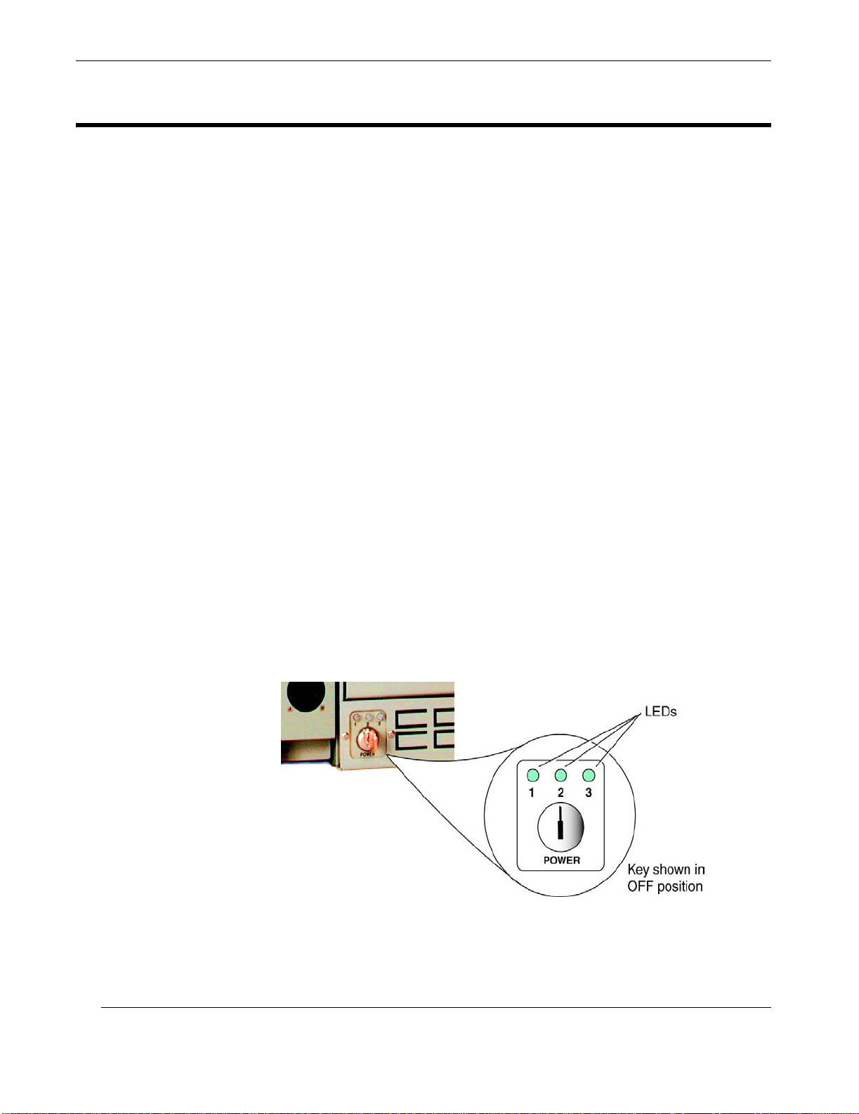
Rugged Enterprise Server 200 Installation Guide
4.2 Themis Management Applications
Themis management applications consist of hardware and software that monitor and
control several components and parameters of the system that are critical to maintaining safe operating power and cooling levels. These components/parameters
include:
• Power supply status LEDs
• VME DC power voltage monitoring
• Cooling system monitoring and control
• System air-flow monitoring
In addition, RES-204 systems contain a Themis-designed circuit called Watchdog
that monitors a malfunction in any of the up-to-4 CPUs contained on the Ultra 80
Motherboard:
• Watchdog (see “Front-Panel Status LEDs”, page 4-9, for more details)
4.2.1 Power Supply Status LEDs
The three LEDs located above the key-switch (see Figure 4-1) at the front of the
RES-204 are used to monitor the performance of each installed power supply. Each
LED is associated with one of the three power supplies installed in the back of the
system. An interpretation of these 2-state LEDs is given in Table 4-1.
4-2
Figure 4-1.
RES-204 Power Supply Status LEDs
Themis Computer
Page 95
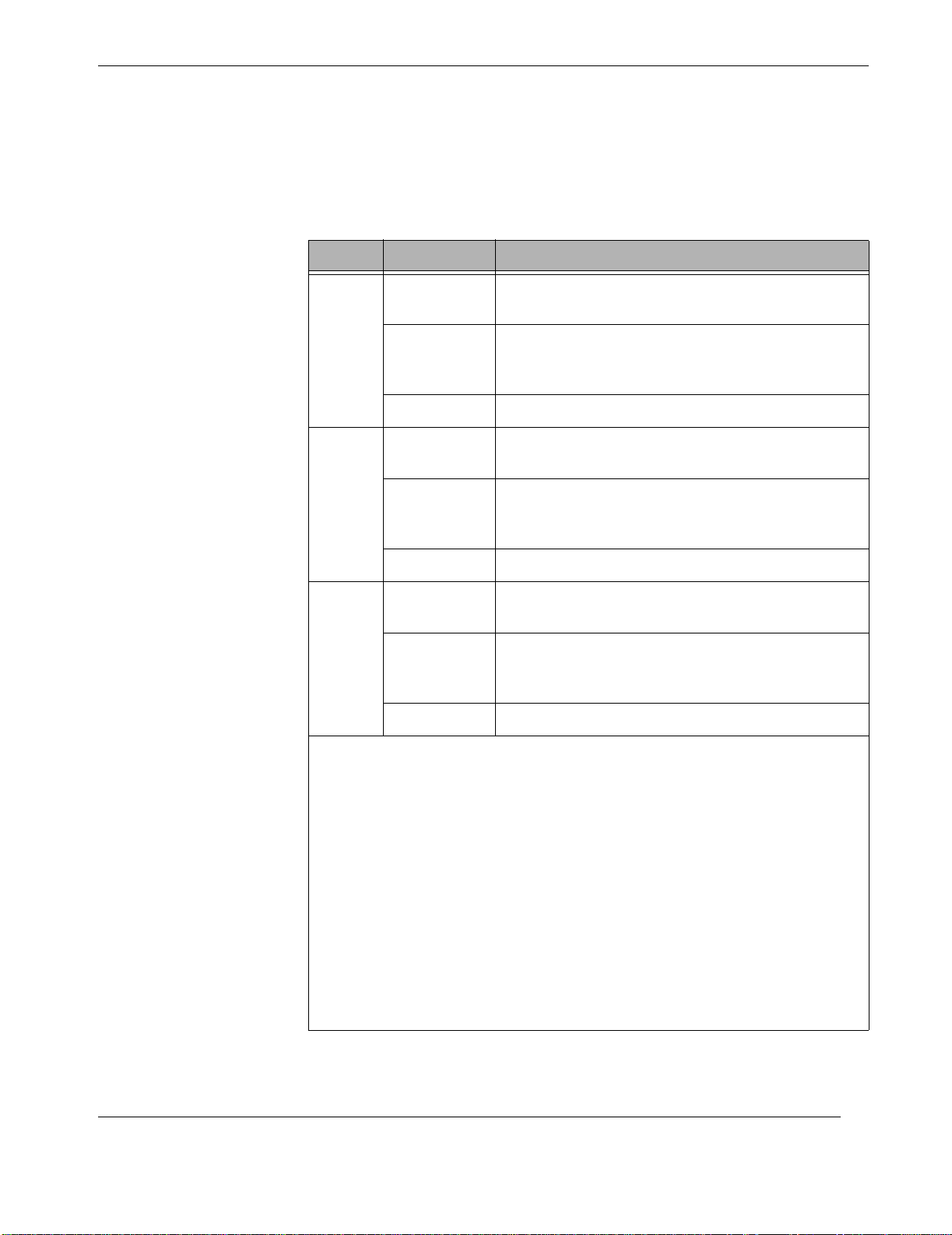
4—Managing Your System
Themis Management Applications
Important: Remember that the power key itself has two positions only—ON when
turned clockwise, and OFF when turned counterclockwise.
LED Status
Green
(normal)
1
Red *
Off (no light) z AC power problem **
Green
(normal)
2
Red *
Off (no light) z AC power problem **
Green
(normal)
3
Red *
Table 4-1.
Power Key-Switch LED Interpretation
z Power Supply 1 is powered up with all outputs op-
erational (key-switch is in ON position)
z Power Supply 1 is NOT fully operational;
however, at least one power supply is outputting
5-volt standby power to the system
z Power Supply 2 is powered up with all outputs op-
erational (key-switch is in ON position)
z Power Supply 2 is NOT fully operational;
however, at least one power supply is outputting
5-volt standby power to the system
z Power Supply 3 is powered up with all outputs op-
erational (key-switch is in ON position)
z Power Supply 3 is NOT fully operational;
however, at least one power supply is outputting
5-volt standby power to the system
Themis Computer
Off (no light) z AC power problem **
* A red LED can be caused by one of three conditions:
1. The power supply module is inhibited (for example, the key-switch is turned off),
even though AC power is applied to the power supply.
2. An internal fault is being reported by the power supply module (the Power_OK
signal from the module is deasserted).
3. There is no power supply module installed in this slot, or the installed power supply has no AC power applied, even though at least one other module is powered up
and supplying 5-volt standby power.
** If one or more LEDs are turned off, one of three conditions may exist:
1. No AC power has been applied to any of the power supply modules in the system
(this is the cause over 99% of the time).
2. If AC power is applied to one or more of the power supply modules, then ALL of
the modules receiving AC power may have defective (i.e., no voltage output) 5-volt
standby power outputs (this is an extremely rare condition).
3. If AC power is applied to one or more of the power supply modules, and at least
one of the modules receiving AC power is properly generating 5-volt standby power,
then the LED illumination circuitry is faulty or the LED itself is burned out (this is an
extremely rare condition).
4-3
Page 96

Rugged Enterprise Server 200 Installation Guide
4.2.2 VME DC Power Voltage Monitoring
Each VME DC power voltage (+2V, +3.3V, +5V, +12V, -12V, and +28V) is monitored to make sure that it does not exceed overvoltage (125%) and overload (115%)
conditions. If the condition cannot be corrected by the system, it will begin a shutdown of all VME power voltages except +28V.
4.2.3 Cooling System Monitoring and Control
The RES-204 cooling system has three sources of air flow (Figure 4-2, page 4-5):
• Three 120-mm fans to cool the Server Subsystem
• Four 80-mm fans in a hot-swappable fan tray to cool the VME Subsystem
• Three fans within each Power Supply (total of nine)
The cooling system is capable of maintaining a maximum ambient temperature of
50°C across the entire system without airflow assist from the outside rack system.
[Maximum temperature rise through the RES-204 does not exceed 10°C.]
4.2.3.1 Server Subsystem Fans
Each of the three 120-mm fans used to cool the Server Subsystem have a separate
harness cable for power and control. Numbered 1, 2, and 3 from top to bottom, the
three fans (configured as N+1 redundant) direct air across the Server Subsystem by
specially placed baffles in the following way:
• Air from Fan 1 (top) and Fan 2 (middle) is directed across the CPU and
DIMM Modules on the Ultra 80 Motherboard
• Air from Fan 3 (bottom) is directed across all installed UPA and PCI boards
In the event of a fan failure, a fan controller detects the faulty condition and instructs
the remaining two fans to run at a faster speed to make up the initial reduction in air
flow. Each fan contains a thermal sensor to record the temperature of the air being
passed through the system. Regulating the speed of each fan not only acts as a temperature control, but as a noise-reduction mechanism as well. In addition to regulating fan speed, the controller can turn the fans completely off.
Note: If a Server Subsystem fan fails, its baffles do not stop air from being delivered to it from other parts of the system. In the event of a failure of any fan in
the system, the remaining fans in the system will accommodate the air flow that
is required to maintain optimum system temperature.
4-4
Air for the Server Fans is pulled through vents at the front of the cabinet on the lefthand side, as indicated in Figure 4-3 on page 4-6, and exhausted through vent-holes
Themis Computer
Page 97
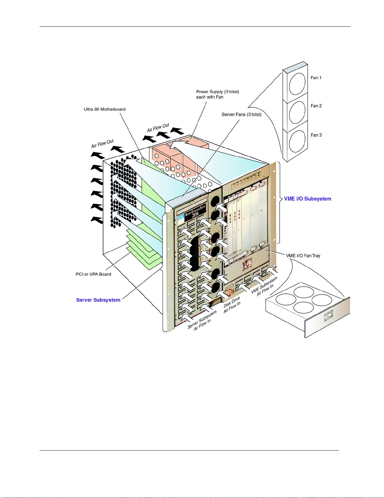
at the rear of the cabinet (see Figure 4-4 on page 4-6).
4—Managing Your System
Themis Management Applications
4.2.3.2 VME I/O Subsystem Fans
Themis Computer
Figure 4-2.
The RES-204 Cooling System
The three 80-mm fans used to cool the VME I/O Subsystem are contained in a single
tray that provides 200 CFM (cubic feet per minute) of air to all installed boards in
the 10 VME slots above it. Easily removed and hot-swappable, the VME I/O Fan
Tray (see Figure 4-2) contains a thermal sensor to record the temperature of the air
being passed through the system. To monitor air flow, each fan in the Fan Tray has
has a tachometer output that is routed to the Buffer/Alarm Board in slot 1 of the
4-5
Page 98
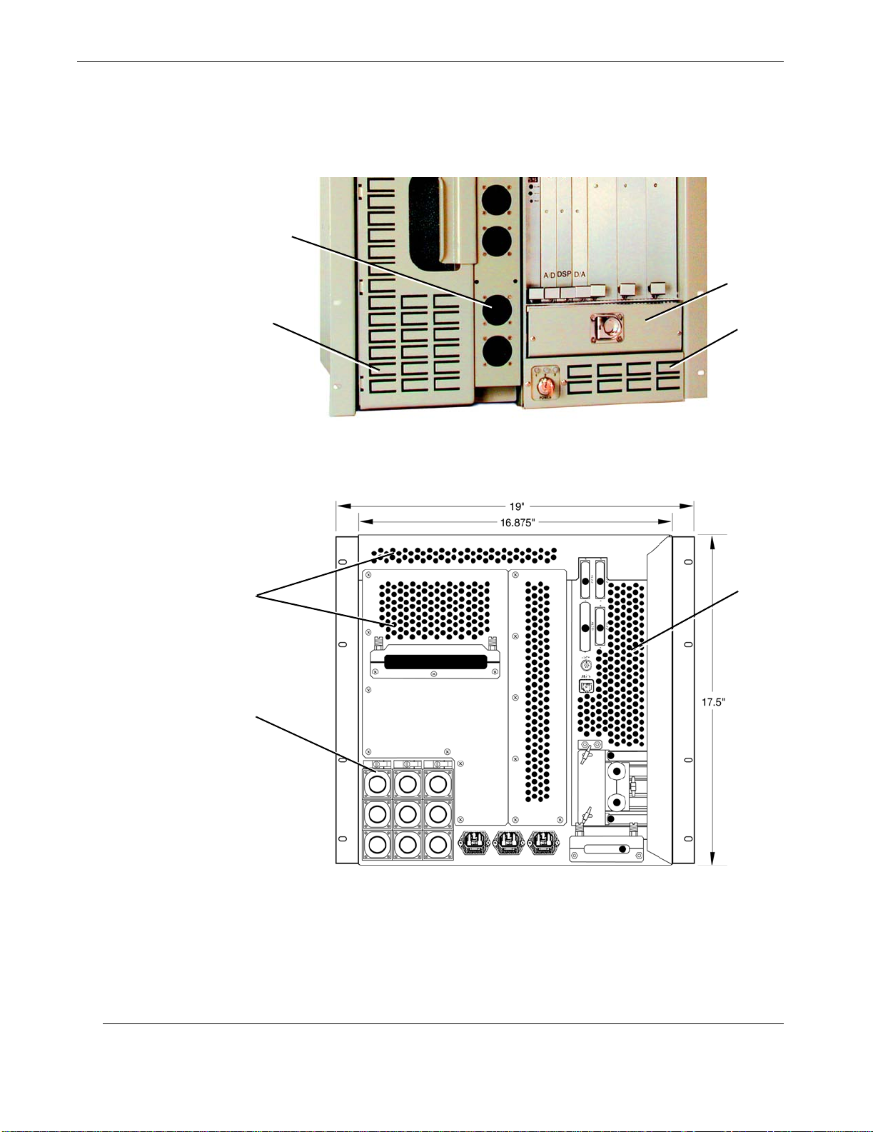
Rugged Enterprise Server 200 Installation Guide
VME I/O Subsystem, and a speed-control input with read-write access through programmable registers. By reading the status of the tachometer output, the fan control-
Air Intake Vents; 6 total
(Disk Drive section)
Air Intake Vents
(Server Subsystem)
Note: Server Fans are
behind Vents
Figure 4-3. Air is Pulled through Vents at the Front of the Cabinet
VME I/O Fan Tray
Air Intake Vents
(VME Subsystem)
VME I/O Subsystem
Air Exhaust Vents
Power Supply
(Total of 3)
ler can determine if it is working properly and act on the speed-control input to
Server Subsystem
Air Exhaust Vent
Figure 4-4. Hot Air is Exhausted from the RES-204 through Rear Vents
4-6
Themis Computer
Page 99

increase or decrease the amount of air flow through the system. Regulating the speed
of the Fan Tray not only acts as a temperature control, but as a noise-reduction
mechanism as well. In addition to regulating Fan Tray speed, the controller can turn
the Fan Tray completely off.
4.2.3.3 Power Supply Fan
Up to three power supplies can be installed in the RES-204, with only one necessary
to operate the system. Each power supply has three fans capable of maintaining an
air flow that can sustain the optimum operational temperature of the power supply.
Air is pulled in through the vents at the front of the cabinet directly under the VME
I/O Fan Tray (Figure 4-3) and exhausted through the vents at the rear directly above
the power-supply slots (Figure 4-4).
4.2.4 System Air Flow Monitoring
In addition to the monitoring and control of individual fans throughout the system,
three thermal sensors have been placed in the air-intake path to record the temperature of the air coming into the system. Controlled through the front VME backplane,
the air-intake temperature is compared with thermal sensors placed at the air-exhaust
path, and measures a temperature gradient through the entire system in order to
report abnormal overheating.
4—Managing Your System
Themis Management Applications
Should an abnormal temperature condition be reported, an attempt is made to correct
the cause of the abnormality by increasing the speed of the fans directly affecting
that area of the system. If the temperature continues to rise, the system will begin an
orderly shutdown of both Server and VME I/O Subsystems.
Themis Computer
4-7
Page 100
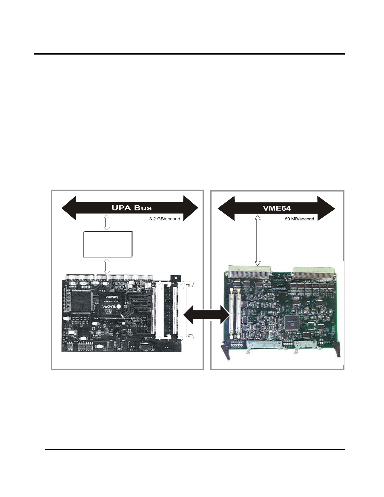
Rugged Enterprise Server 200 Installation Guide
V
V
4.3 Status/Alarm Monitoring and Control
All of the monitoring and control status information discussed in the previous section is collected onto the VME Buffer/Alarm Board in VME slot 1, which in turn
communicates through a VME Bridge Cable interface connected to a Themis
VME-Bridge PCI Card (see Figure 4-5) installed in PCI slot 3 of the Server Subsystem (see Figure 2-15 on page 2-14). This specialized PCI card contains a Tundra
Universe II IC chip that performs a VME-to-PCI conversion before sending signals
to the PCI bus. In effect, the VME bus operates as a virtual extension of the local
PCI bus of the Server Subsystem.
[See Sidebar, next page, for more details on the VME Buffer/Alarm Board.]
Ultra 80 Motherboard
UPA-to-PCI
(U2P)
Interface Chip
PCI Bus
VME- Bridge PCI Card
PCI
Slot 3
s
VME I/O Subsystem
VME
Slot 1
ME Interface
ME Buffer/Alarm Board
Figure 4-5. Data Flow through the VME Buffer/Alarm Card within the RES-204
The VME Buffer/Alarm Board is unique in that it is the only circuit board connected
directly with both the Server GigaplaneTM bus (100 MHz) and the VME bus (80
Mbps) of the RES-204).
4-8
Themis Computer
 Loading...