

Page 1

Thecus
N0204
N2200/PLUS/EVO
N4100EVO
User‘s Manual V2.8
Page 2

2
Copyright and Trademark Notice
Thecus and other names of Thecus products are registered trademarks of Thecus
Technology Corp. Microsoft, Windows, and the Windows logo are registered
trademarks of Microsoft Corporation. Apple, iTunes and Apple OS X are registered
trademarks of Apple Computers, Inc. All other trademarks and brand names are the
property of their respective owners. Specifications are subject to change without
notice.
Copyright © 2010 Thecus Technology Corporation. All rights reserved.
About This Manual
All information in this manual has been carefully verified to ensure its correctness.
In case of an error, please provide us with your feedback. Thecus Technology
Corporation reserves the right to modify the contents of this manual without notice.
Product name: Thecus N0204/N2200/N2200PLUS/N2200EVO/N4100EVO
Manual Version: 2.8
Release Date: November 2012
Limited Warranty
Thecus Technology Corporation guarantees all components of Thecus NAS products
are thoroughly tested before they leave the factory and should function normally
under general usage. In case of any system malfunctions, Thecus Technology
Corporation and its local representatives and dealers are responsible for repair
without cost to the customer if the product fails within the warranty period and
under normal usage. Thecus Technology Corporation is not responsible for any
damage or loss of data deemed to be caused by its products. It is highly
recommended that users conduct necessary back-up practices.
Page 3

3
Safety Warnings
For your safety, please read and follow the following safety warnings:
Read this manual thoroughly before attempting to set up your Thecus IP
storage.
Your Thecus IP storage is a complicated electronic device. DO NOT attempt
to repair it under any circumstances. In the case of malfunction, turn off the
power immediately and have it repaired at a qualified service center. Contact
your vendor for details.
DO NOT allow anything to rest on the power cord and DO NOT place the
power cord in an area where it can be stepped on. Carefully place connecting
cables to avoid stepping or tripping on them.
Your Thecus IP storage can operate normally under temperatures between
5°C and 40°C, with relative humidity of 20% – 85%. Using Thecus IP storage
under extreme environmental conditions could damage the unit.
Ensure that the Thecus IP storage is provided with the correct supply voltage
(AC 100V ~ 240V). Plugging the Thecus IP storage to an incorrect power
source could damage the unit.
Do NOT expose Thecus IP storage to dampness, dust, or corrosive liquids.
Do NOT place Thecus IP storage on any uneven surfaces.
DO NOT place Thecus IP storage in direct sunlight or expose it to other heat
sources.
DO NOT use chemicals or aerosols to clean Thecus IP storage. Unplug the
power cord and all connected cables before cleaning.
DO NOT place any objects on the Thecus IP storage or obstruct its ventilation
slots to avoid overheating the unit.
Keep packaging out of the reach of children.
If disposing of the device, please follow your local regulations for the safe
disposal of electronic products to protect the environment.
Page 4

4
Table of Contents
Copyright and Trademark Notice ................................................... 2
About This Manual ......................................................................... 2
Limited Warranty ........................................................................... 2
Safety Warnings ............................................................................ 3
Table of Contents .......................................................................... 4
Chapter 1: Introduction ................................................................. 7
Overview ............................................................................................... 7
Product Highlights ................................................................................. 7
Front Panel ............................................................................................ 9
Rear Panel ........................................................................................... 12
Chapter 2: Hardware Installation ................................................ 19
Overview ............................................................................................. 19
Before You Begin ................................................................................. 19
Hard Disk Installation.......................................................................... 19
Cable Connections ............................................................................... 21
Chapter 3: First Time Setup ......................................................... 27
Thecus Smart Utility (N0204/N2200) ....................................................... 27
Thecus Setup Wizard (N2200PLUS/EVO,N4100EVO) .................................... 31
LCD Operation ..................................................................................... 33
LCD Controls ............................................................................... 33
Display Mode .............................................................................. 33
USB Copy ............................................................................................. 34
Typical Setup Procedure ...................................................................... 35
Chapter 4: System Administration ............................................... 37
Overview ............................................................................................. 37
Web Administration Interface ............................................................. 37
My Favorite ................................................................................. 38
Logout ....................................................................................... 40
Language Selection ...................................................................... 40
System Information ............................................................................. 41
Product Information ..................................................................... 41
System/Service Status ................................................................. 41
Logs .......................................................................................... 42
System Management ........................................................................... 43
Time: Setting system time ............................................................ 43
Notification configuration .............................................................. 44
Firmware Upgrade ....................................................................... 44
Schedule Power On/Off (N0204/N2200/EVO,N4100EVO) ........................ 45
UPS Setting (Only for N2200) .......................................................... 46
Utility ......................................................................................... 47
System Network .................................................................................. 50
WAN/LAN1 .................................................................................. 51
LAN2 (Only for N2200PLUS/N2200EVO/N4100EVO) ................................ 52
DHCP Server Configuration............................................................ 52
Samba / CIFS ............................................................................. 53
AFP (Apple Network Setup) ........................................................... 53
NFS Setup .................................................................................. 54
FTP ............................................................................................ 54
HTTP/ Web Disk .......................................................................... 55
UPnP .......................................................................................... 56
Page 5

5
Nsync Target ............................................................................... 56
Bonjour Setting ........................................................................... 57
TFTP .......................................................................................... 57
DDNS ......................................................................................... 57
Storage Management ........................................................................... 57
Disks Information ........................................................................ 58
S.M.A.R.T. Information ................................................................. 59
Bad Block Scan ............................................................................ 60
RAID Information......................................................................... 60
Create a RAID (Only for N2200PLUS/EVO,N4100EVO) .................................. 61
RAID Level ............................................................................................. 62
Edit RAID .............................................................................................. 63
Remove RAID ......................................................................................... 63
Space Allocation .......................................................................... 64
iSCSI Target/USB Target .................................................................. 64
Share Folder ............................................................................... 70
Adding Folders ....................................................................................... 70
Modify Folders ........................................................................................ 71
Remove Folders ...................................................................................... 71
NFS Share ............................................................................................. 72
Folder and Sub-Folder Access Control List (ACL) .......................................... 73
ISO Mount .................................................................................. 75
User and Group Authentication ............................................................ 77
Local User Configuration ............................................................... 78
Remove Users ........................................................................................ 79
Local Group Configuration ............................................................. 80
Add Groups ............................................................................................ 80
Edit Groups ............................................................................................ 81
Remove Groups ...................................................................................... 81
Batch Create Users and Groups ...................................................... 82
Application Server ............................................................................... 82
Printer Information ...................................................................... 83
Windows XP SP2 .......................................................................... 83
Windows Vista ............................................................................. 84
iTunes® Server ........................................................................... 87
Module Management ........................................................................... 88
Module Installation ....................................................................... 88
Auto Module Installation ............................................................... 88
System Module .................................................................................... 89
Backup ................................................................................................ 90
Nsync ........................................................................................ 90
Chapter 5: Using Thecus IP Storage ............................................ 93
Overview ............................................................................................. 93
Login Page ........................................................................................... 93
Using WebDisk(Does not apply to the N2200EVO/N4100EVO‘ WebDisk) ............. 94
Photo Server(Does not apply to the N2200EVO/N4100EVO‘ photo server) ............ 96
Windows XP Publishing Wizard ....................................................... 97
Managing Albums and Photos ...................................................... 102
Creating Albums ........................................................................ 103
Password Protecting Albums ........................................................ 103
Uploading Pictures to Albums ...................................................... 103
EXIF Information ....................................................................... 103
Slide Shows .............................................................................. 104
Mapping a Client PC to the Thecus IP Storage ................................... 104
Windows .................................................................................. 104
Apple OS X ............................................................................... 105
Chapter 6: Tips and Tricks ......................................................... 106
Page 6

6
USB Storage Expansion ..................................................................... 106
Replacing Damaged Hard Drives ........................................................ 106
Hard Drive Damage .................................................................... 106
Replacing a Hard Drive ............................................................... 106
RAID Auto-Rebuild ..................................................................... 107
Chapter 7: Troubleshooting ....................................................... 108
Forgot My Network IP Address .......................................................... 108
Resetting NAS IP Address and Admin Password (N2200/EVO/PLUS) ...... 108
Can't Map a Network Drive in Windows XP ........................................ 108
Restoring Factory Defaults ................................................................ 109
Problems with Time and Date Settings .............................................. 109
Appendix A: Customer Support .................................................. 110
Appendix B: RAID Basics ........................................................... 111
Overview ........................................................................................... 111
Benefits ............................................................................................. 111
Improved Performance ............................................................... 111
Data Security ............................................................................ 111
RAID Levels ....................................................................................... 111
Disk Usage ......................................................................................... 112
Appendix C: Licensing Information ............................................ 113
Overview ........................................................................................... 113
Source Code Availability .................................................................... 113
CGIC License Terms ........................................................................... 114
GNU General Public License ............................................................... 114
Page 7

7
Chapter 1: Introduction
Overview
Thank you for choosing the Thecus IP Storage NAS Server. The Thecus IP storage is
an easy-to-use storage server that allows a dedicated approach to storing and
distributing data on a network. Data reliability is ensured with RAID features that
provide data security and recovery. Gigabit Ethernet ports enhance network
efficiency, allowing Thecus IP storage to take over file management functions,
increase application and data sharing and provide faster data response. The Thecus
IP storage offers data mobility with a disk roaming feature that lets you swap
working hard drives for use in other Thecus IP storage, securing the continuity of
data in the event of hardware failure. The Thecus IP storage allows data
consolidation and sharing between Windows (SMB/CIFS), UNIX/Linux, and Apple
OS X environments. The Thecus IP storage‘s user-friendly GUI supports multiple
Languages.
Product Highlights
File Server
First and foremost, the Thecus IP storage allows you to store and share files over an
IP network. With a Network Attached Storage (NAS) device, you can centralize your
files and share them easily over your network. With the easy-to-use web-based
interface, users on your network can access these files in a snap.
To learn about the Web User Interface, go to
Chapter 5: Using the Thecus IP Storage > Using WebDisk.
FTP Server
With the built-in FTP Server, friends, clients, and customers can upload and
download files to your Thecus IP storage over the Internet with their favorite FTP
programs. You can create user accounts so that only authorized users have access.
To set up the FTP Server, refer to
Chapter 4: System Network> FTP .
iTunes Server
With the built-in iTunes server capability, the Thecus IP storage enables digital
music to be shared and played anywhere on the network!
To set up the iTunes Server, refer to
Chapter 4: Application Server>iTunes Configuration.
Backup Server
Don‘t leave precious data to chance. With advanced backup capabilities, you can
easily upload mission critical files to the Thecus IP storage, and even automate your
backup tasks for true peace-of-mind.
To find out how to backup your files with the Thecus IP storage, refer to
Chapter 4: Backup >Nsync.
Page 8

8
Printer Server
With the Thecus IP storage‘s Printer Server, you can easily share an IPP printer with
other PCs connected to your network.
To set up the Printer Server, refer to
Chapter 4: Application Server>Printer Information.
Superior Power Management (Only for N0204/N2200/EVO,N4100EVO)
Thecus IP storage supports schedule power on/off. With this feature, administrator
can set at what time to turn on or off the system. This feature is a big plus for people
who want to conserve energy. Wake-On-LAN enables administrator to remotely turn
on the system without even leaving their own seat.
To schedule system on and off, refer to
Chapter 4: System Management> Scheduled Power On/Off
Page 9

9
Front Panel
N0204:
The Thecus N0204 miniNAS‘s front panel has the USB copy button, indicators, and
USB port:
Front Panel
Item
Description
USB copy
Button/LED
Copy USB storage contents to N0204 miniNAS
Blinking Green: Copy activity
Solid Green: Copy Success
Solid Red: Copy Fail
HDD 1 LED
Solid Red: HDD failed
Blinking Green: HDD activity
HDD 2 LED
Solid Red: HDD failed
Blinking Green: HDD activity
LAN LED
Solid Green: network link
Blinking Orange: network activity
Power LED
Solid Blue: system is powered on
USB 2.0 Port
USB 2.0 port for compatible USB devices, such as digital cameras,
USB disks.
HDD2 LED
USB copy Button/LED
HDD1 LED
LAN LED
Power LED
USB 2.0 Port
Page 10

10
N2200:
The Thecus N2200‘s front panel has the device‘s controls, indicators, and hard disk
trays:
Front Panel
Item
Description
Power LED
Solid blue: system is ready
Blinking Blue: system is re-build
Power Button
Power on/off N2200
LCD
Displays current system status and messages
HDD 1 LED
Blinking Yellow: HDD activity
Blinking Red: HDD failure
HDD 2 LED
Blinking Yellow: HDD activity
Blinking Red: HDD failure
WAN LED
Blinking green: network activity
USB Copy
● Blinking Blue: USB Copy activity
● Blinking Red: USB Copy failure
HDD Tray
Two HDD trays support 2x 3.5" or 2 x 2.5‖ HDDs
USB Copy Button
Copy USB storage contents to N2200
USB Port
(Device Mode)
USB 2.0 port for compatible USB devices, such as digital cameras,
USB disks, USB printers.
Power LED
Power Button
LCD
USB Copy Button
USB Port (Device Mode)
Front Door
HDD 1
HDD 2
HDD Tray
Page 11

11
N2200PLUS:
The Thecus N2200PLUS‘s front panel has the device‘s controls, indicators, and hard
disk trays:
Front Panel
Item
Description
Power LED
Solid blue: system is ready
Blinking Blue: system is re-build
Power Button
Power on/off N2200PLUS
LCD
Displays current system status and messages
HDD 1 LED
Blinking Yellow: HDD activity
Blinking Red: HDD failure
HDD 2 LED
Blinking Yellow: HDD activity
Blinking Red: HDD failure
WAN LED
LAN LED
Blinking green: network activity
Blinking green: network activity
USB Copy
● Blinking Blue: USB Copy activity
● Blinking Red: USB Copy failure
HDD Tray
Two HDD trays support 2x 3.5" or 2 x 2.5‖ HDDs
USB Copy Button
Copy USB storage contents to N2200PLUS. (use rear USB port)
USB Port
(Target Mode)
USB 2.0 port to connect to PC (Type A of target mode)
Power LED
Power Button
LCD
USB Copy Button
USB Port ( Target Mode)
Front Door
HDD 1
HDD 2
Page 12

12
N2200EVO:
The Thecus N2200EVO‘s front panel has the device‘s controls, indicators, and hard
disk trays:
Front Panel
Item
Description
Power LED
Solid blue: system is ready
Blinking Blue: system is re-build
Power Button
Power on/off N2200EVO
LCD
Displays current system status and messages
HDD 1 LED
Blinking Yellow: HDD activity
Blinking Red: HDD failure
HDD 2 LED
Blinking Yellow: HDD activity
Blinking Red: HDD failure
WAN LED
LAN LED
Blinking green: network activity
Blinking green: network activity
USB Copy
● Blinking Blue: USB Copy activity
● Blinking Red: USB Copy failure
HDD Tray
Two HDD trays support 2x 3.5" or 2 x 2.5‖ HDDs
USB Copy Button
Copy USB storage contents to N2200EVO. (use rear USB port)
USB Port
(Target Mode)
USB 2.0 port to connect to PC (Type A of target mode)
Power LED
Power Button
LCD
USB Copy Button
USB Port ( Target Mode)
Front Door
HDD 1
HDD 2
Page 13

13
N4100EVO
The N4100EVO‘s front panel displays the unit‘s array of status LED‘s and is also
where you‘ll find the power buttons. See the table below for a detailed explanation
of each:
Item
Description
HDD Trays
There are four hard disk drive (HDD) trays. Each tray supports
a 3.5-inch SATA HDD. The trays have locks for added physical
security and keys are provided with the package.
Power LED
Solid blue: N4100EVO is powered on
Busy LED
Blinking orange: system startup or maintenance; data
inaccessible
Off: system startup complete; system operating normally
WAN LED
Solid green: network link
Blinking green: network activity
LAN LED
Solid green: network link
Blinking green: network activity
Error LED
Solid red: system error detected
Power Button
Power on/off N4100EVO
Page 14

14
Rear Panel
N0204:
The Thecus N0204 miniNAS‘s rear panel features ports and connectors.
HDD1
HDD2
LAN Port
HDD Tray
Power socket
Power Button
USB 1.1 Port
Page 15

15
N2200:
The N2200 rear panel features ports and connectors.
Back Panel
Item
Description
System Fan
System fan that exhausts heat from the unit
LAN Port
LAN port for connecting to an Ethernet network through a switch
or router
Reset Button
Resets the N2200
Immediately press the Reset button on the back. This will reset
your network setting, password.
USB Port
USB 2.0 port for compatible USB devices, such as digital cameras,
USB disks, and USB printers
DC IN
For connect the power adaptor
System Fan
LAN Port
USB Port
Reset Button
DC IN
Page 16

16
N2200PLUS:
The N2200PLUS rear panel features ports and connectors.
Back Panel
Item
Description
System Fan
System fan that exhausts heat from the unit
WAN Port
WAN port for connecting to an Ethernet network through a switch
or router
LAN Port
LAN port for connecting to an Ethernet network through a switch
or router
Reset Button
Resets the N2200PLUS
Immediately press the Reset button on the back. This will reset
your network setting, password.
USB Port
USB 2.0 port for compatible USB devices, such as digital cameras,
USB disks, and USB printers.
DC IN
For connect the power adaptor
System Fan
WAN Port
USB Port
Reset Button
DC IN
LAN Port
Page 17

17
N2200EVO:
The N2200EVO rear panel features ports and connectors.
Back Panel
Item
Description
System Fan
System fan that exhausts heat from the unit
WAN Port
WAN port for connecting to an Ethernet network through a switch
or router
LAN Port
LAN port for connecting to an Ethernet network through a switch
or router
Reset Button
Resets the N2200EVO
Immediately press the Reset button on the back. This will reset
your network setting, password.
USB Port
USB 2.0 port for compatible USB devices, such as digital cameras,
USB disks, and USB printers.
DC IN
For connect the power adaptor
System Fan
WAN Port
USB Port
Reset Button
DC IN
LAN Port
Page 18

18
N4100EVO
The rear panel of the N4100EVO houses the USB and Ethernet connections, as well
as the power connector. See the table below for descriptions of each:
Item
Description
Power Connector
Connect the included power cord to this connector
WAN Port
WAN port for connecting to an Ethernet network through a switch
or router
LAN Port
LAN port for connecting to an Ethernet network through a switch or
router
USB Ports
USB 2.0 ports for storage expansion
USB Port
LAN Port
WAN Port
Power Connector
Page 19

19
Chapter 2: Hardware Installation
Overview
Your Thecus IP storage is designed for easy installation. To help you get started, the
following chapter will help you quickly get your Thecus IP storage up and running.
Please read it carefully to prevent damaging your unit during installation.
Before You Begin
Before you begin, be sure to take the following precautions:
1. Read and understand the Safety Warnings outlined in the beginning of the
manual.
2. If possible, wear an anti-static wrist strap during installation to prevent static
discharge from damaging the sensitive electronic components on the IP
storage.
3. Be careful not to use magnetized screwdrivers around the Thecus IP
storage‘s electronic components.
Hard Disk Installation
N0204:
The N0204 miniNAS supports two standard 2.5‖ Serial ATA (SATA) hard disks. To
install a hard disk into the N0204 miniNAS, follow the steps below:
1. Open 2.5‖ HDD tray from N0204 miniNAS, as the following chart.
Push down
Push up
Page 20

20
2. Install HDD on the tray, as the following chart:
3. Install the tray with HDD into N0204 miniNAS,
please note that the HDD-1 is in left side and
HDD-2 is in right side. The triangular symbol of
tray must be corresponding with the triangular
symbol of back panel. Push the tray back.
N2200/PLUS/EVO:
The N2200/PLUS/EVO supports both 2.5‖ and 3.5‖ Serial ATA (SATA) hard disks. To
install a hard disk into the N2200/PLUS/EVO, follow the steps below:
1. Open front cover of the N2200/PLUS/EVO.
2. For 3.5‖ HDDs
a. Remove an HDD tray and install a 3.5‖ SATA hard disk onto it.
4 screws here
Page 21

21
b. Slide the HDD tray back into the N2200/N2200PLUS until it snaps into
place.
3. For 2.5‖ HDDs
c. Remove an HDD tray and install a 2.5‖ SATA hard disk onto it.
d. Slide the HDD tray back into the N2200/PLUS/EVO until it snaps into
place.
Cable Connections
N0204:
To connect the N0204 miniNAS to your network, follow the steps below:
1. Connect an Ethernet cable from your network to the LAN port on the back
panel of the N0204 miniNAS.
2. Connect the provided power adaptor into
the power socket on the back panel. Plug
the other end of the cord into a surge
protector socket.
3. Press the Power button on the Rear end
to boot up or shut down the N0204 miniNAS.
NOTE
1. USB copy LED will be flashed Blue
light during the system are
booting and will be dull after the
booting complete.
2. To shut down the system, press
the power button over 4 seconds,
then USB copy LED will be flashed
Red light, release power button.
Page 22

22
N2200:
To connect the N2200 to your network, follow the steps below:
1. Connect an Ethernet cable from your network to the LAN port on the back
panel of the N2200.
2. Connect the provided power cord into the power socket on the back panel.
3. Press the power button boot up the N2200.
Page 23

23
N2200PLUS:
To connect the N2200PLUS to your network, follow the steps below:
1. Connect an Ethernet cable from your network to the WAN port on the back
panel of the N2200PLUS.
2. Connect the provided power cord into the power socket on the back panel.
3. Press the power button boot up the N2200PLUS.
Page 24

24
N2200EVO:
To connect the N2200EVO to your network, follow the steps below:
1. Connect an Ethernet cable from your network to the WAN port on the back
panel of the N2200EVO.
3. Connect the provided power cord into the power socket on the back panel.
3. Press the power button boot up the N2200EVO.
Page 25

25
N4100EVO:
The N4100EVO supports four standard 3.5‖ or 2.5‖ Serial ATA (SATA) hard disks. To
install a hard disk into the N4100EVO, follow the steps below:
1. Remove a hard disk tray from the N4100EVO.
2. Slide the new SATA hard disk into the tray and fasten the screws.
3. Insert the hard disk and tray back into the N4100EVO until it snaps into place
and lock it with a key if desired.
4. The LED blinks green when the hard disk is plugged in.
Hard Disk Trays
Each of above mentioned models‘ hard disk trays has a lock, a latch, and two LED
indicators:
Hard Disk Trays
Item
Description
1.HDD Power LED
Solid blue: Hard disk is powered on
2.HDD
Access/Error LED
Solid green:When the HDD is plugged in.
Blinking green: System is accessing data on the hard disk
Solid red: HDD fail
3.Lock
Use the lock to physically secure the hard disk to the unit.
4.Latch
Use to open and remove or close and secure the tray.
5.Handle
Pull to remove the HDD tray.
Cable Connections
Make the following connections on the Thecus N4100EVO and then power up the
unit:
1. Connect an Ethernet cable from your network to the WAN port on the back
panel of the N4100EVO.
NOTE
If your HDD was part of a RAID 1 or RAID 5 array previously, it
automatically rebuilds. If you replace all the drives with higher capacity
drives, you will need to go to Administrator login and format the drives.
NOTE
After turning on the NAS, the light "activity" will become bright while the
HDD is plugged in, and will glitter while reading or writing information.
Page 26

26
2. Connect the provided power cord into the universal power socket on the
back panel. Plug the other end of the cord into a surge protected socket.
3. Press the power button on the front panel to power on the N4100EVO.
Checking System Status
After making connections on the N4100EVO and powering up, check whether the
system status is normal or has trouble by observing indicators on the front panel
and hard disk trays.
System Status Normal
The system status is normal if:
1. The front panel Power LED glows blue and the WAN LED glows or blinks
green.
2. The HDD Power LED on each HDD tray glows blue.
Page 27

27
Chapter 3: First Time Setup
Once the hardware is installed, physically connected to your network, and powered
on, you can configure the Thecus IP storage so that it is accessible to your network
users. There is one way to set up your Thecus IP storage: using the Thecus Smart
Utility(N2200/N0204) /Thecus Setup Wizard(N2200Plus/EVO,N4100EVO).
Follow the steps below for initial software setup.
Thecus Smart Utility (N0204/N2200)
The handy Thecus Smart Utility makes configuring N0204/N2200 a snap. To
configure the Thecus IP storage using the Smart Utility, perform the following steps:
1. Insert the installation CD into your CD-ROM drive (the host PC must be
connected to the network).
2. The Smart Utility should launch automatically. If not, please browse your
CD-ROM drive and double click on autorun.exe. Click “N0204/N2200 ”.
3. Select the N0204/N2200 that you like to configure. Press Next to continue.
4. First, please select System Installation Wizard.
NOTE
For MAC OS X users, double click on Thecus Smart Utility Wizard .pkg file.
Page 28

28
5. Please select your installation mode, One Click Installation or Manual
Installation.
6. After your installed HDDs are detected, select your desired RAID level. Press
Next to continue.
7. The N0204/N2200 will automatically create several folders. Select your
desired folder and map it to your local PC/NB as a Network Device.
Page 29

29
8. Complete the N0204/N2200 Smart Utility Wizard.
A. You can access the N0204/N2200 Web Administrator interface by clicking
the Start Brower button. The default password is ―admin‖. You can also
setup a backup task at this point by clicking the Setup backup task button.
B. Press Exit to exit the windows utility.
C. Press the Setup backup task button to configure backup tasks on your
N0204/N2200.
NOTE
The Thecus Smart Utility Wizard is designed for installation on systems running
Windows XP/2000/7 or Mac OSX or later. Users with other operating systems will
need to install the Thecus Smart Utility Wizard on a host machine with one of
these operating systems before using the unit.
Page 30

30
‧Single Task Quick Backup: Perform a single backup by selecting the source
and destination.
‧Manually Backup and Task List: Show all task information and options.
Page 31

31
Thecus Setup Wizard (N2200PLUS/EVO,N4100EVO)
The handy Thecus Setup Wizard makes configuring N2200PLUS/EVO,N4100EVO a
snap. To configure the N2200PLUS/EVO,N4100EVO using the Setup Wizard,
perform the following steps:
1. Insert the installation CD into your CD-ROM drive (the host PC must be
connected to the network).
2. The Setup Wizard should launch automatically. If not, please browse your
CD-ROM drive and double click on Setup.exe.
3. The Setup Wizard will start and automatically detect all Thecus storage
devices on your network. If none are found, please check your connection
and refer to Chapter 7: Troubleshooting for assistance.
4. Select the N2200PLUS/EVO,N4100EVO that you like to configure.
5. Login with the administrator account and password. The default account and
password are both ―admin‖.
NOTE
For MAC OS X users, double click on Thecus Setup Wizard .dmg file.
Page 32

32
6. Name your N2200PLUS/EVO,N41OOEVO and configure the network IP
address. If your switch or router is configured as a DHCP Server, configuring
the N2200PLUS/EVO,N4100EVO to automatically obtain an IP address is
recommended. You may also use a static IP address and enter the DNS
Server address manually.
7. Change the default administrator password.
8. Finished! Access the N2200PLUS/EVO,N4100EVO Web Administrator
Interface by pressing the Start Browser button. You can also configure
another N2200PLUS/EVO,N4100EVO at this point by clicking the Setup
Other Device button. Press Exit to exit the wizard.
Page 33

33
LCD Operation
The N4100EVO is equipped with an LCD on the front for easy status display and
setup. There are four buttons on the front panel to control the LCD functions.
LCD Controls
Use the Down (▼), Up (▲), Enter () and Escape (ESC) keys to operate LCD to
view system information and USB copy.
The following table illustrates the keys on the front control panel:
LCD Controls
Icon
Function
Description
▲
Up Button
Select the previous configuration settings information.
▼
Down Button
Select the next configuration settings information
Enter
Enter for the USB copy confirmation message.
ESC
Escape
Escape and return to the previous menu.
There is one mode of operation for the LCD: Display Mode
Display Mode
During normal operation, the LCD will be in Display Mode.
Display Mode
Item
Description
Host Name
Current host name of the system.
WAN
Current WAN IP setting.
LAN
Current LAN IP setting.
Disk Info
Current status of disk slot has been installed
RAID
Current RAID status.
System Fan
Current system fan status.
2006/06/16 12:00
Current system time.
NOTE
The Thecus Setup Wizard is designed for installation on systems running Windows
XP/2000/vista/7 or Mac OSX or later. Users with other operating systems will
need to install the Thecus Setup Wizard on a host machine with one of these
operating systems before using the unit.
Page 34

34
The N4100 Eco will rotate these messages every one-two seconds on the LCD
display.
USB Copy
The USB Copy function enables you to copy files stored on USB devices such as USB
disks and digital cameras to the Thecus IP storage by press USB copy button. To use
USB copy, follow the steps below:
N0204:
1. Plug your USB device into USB2.0 port on the Front Panel.
2. Press USB copy Button and the N0204 miniNAS will start copying USB disks
connected to the front end USB2.0 port.
3. The USB LED show
Blinking Green: Copy activity.
Solid Green: Copy Success.
Solid Red: Copy Fail.
N2200:
1. Plug your USB device into an available USB port on the Front Panel.
2. Press the ―USB Copy Button”.
3. The N2200 will start copying USB disks connected to the front USB port. The
LCD will display the USB copy progress and result.
USB 2.0 Copy
NOTE
Please use the front USB port when
using USB copy function.
Page 35

35
N2200PLUS/EVO:
1. Plug your USB device into an available USB port on the Rear Panel.
2. Press the ―USB Copy Button”.
3. The N2200PLUS will start copying USB disks connected to the rear USB port.
The LCD will display the USB copy progress and result.
N4100EVO:
The USB Copy function enables you to copy files stored on USB devices such as USB
disks and digital cameras to the N4100EVO with a press of a button. To use USB
copy, follow the steps below:
1. Plug your USB device into an available USB port on the Front Panel.
2. In Display Mode, press the Enter ().
3. The LCD will display ―USB Copy?‖
4. Press Enter () and the N4100EVO will start copying USB disks connected to
the front USB port.
5. All of data will be copied into system folder named ―USBcopy‖.
Typical Setup Procedure
From the Web Administration Interface, you can begin to setup your Thecus IP
storage for use on your network. Setting up the Thecus IP storage typically follows
the five steps outlined below.
For more on how to use the Web Administration Interface, see
Chapter 4: Web Administration Interface.
Page 36

36
Step 1: Network Setup
From the Web Administration Interface, you can configure the network settings of
the Thecus IP storage for your network. You can access the Network menu from
the menu bar.
For details on how to configure your network settings, refer to
Chapter 4: System Network .
Step 2: RAID Creation
Next, administrators can configure their preferred RAID setting and build their RAID
volume. You can access RAID settings from the menu bar of the Web Administration
Interface by navigating to Storage Management > RAID Configuration.
For more information on configuring RAID, see
Chapter 4: System Management > RAID Configuration.
Don‘t know which RAID level to use? Find out more about the different RAID levels
from Appendix B: RAID Basics.
Step 3: Create Local Users or Setup Authentication
Once the RAID is ready, you can begin to create local users for the IP STORAGE, or
choose to setup authentication protocols such as Active Directory (AD).
For more on managing users, go to Chapter 4:User and Group Authentication.
Step 4: Create Folders and Set Up ACLs
Once users are introduced into your network, you can begin to create various folders
on the Thecus IP storage and control user access to each using Folder Access
Control Lists.
More information on managing folders, see
Chapter 4: Storage Management > Share Folder .
To find out about configuring Folder Access Control Lists, see Chapter 4: Storage
Management > Share Folder> Folder Access Control List (ACL).
Step 5: Start Services
Finally, you can start to setup the different services of the IP Storage for the users
on your network. You can find out more about each of these services by clicking
below:
SMB/CIFS
Apple File Protocol (AFP)
Network File System (NFS)
File Transfer Protocol (FTP)
iTunes Server
Printer Server
Page 37

37
Chapter 4: System Administration
Overview
The Thecus IP storage provides an easily accessible Web Administration
Interface. With it, you can configure and monitor the Thecus IP storage anywhere
on the network.
Web Administration Interface
Make sure your network is connected to the Internet. To access Thecus IP storage
Web Administration Interface:
1. Type the Thecus IP storage IP address into your browser. (Default IP address
is http://192.168.1.100) (N0204/N2200 default IP address is DHCP)
2. Login to the system using the administrator user name and password. The
factory defaults are:
User Name: admin
Password: admin
※ If you changed your password in the smart utility/setup wizard,
use the new password.
Once you are logged in as an administrator disclaimer page will appear as below.
Please click the check box if you do not want to have this page displayed during the
next login.
NOTE
Your computer‘s network IP address must be on the same subnet as the Thecus
IP storage. If the Thecus IP storage has default IP address of 192.168.1.100,
your managing PC IP address must be 192.168.1.x, where x is a number
between 1 and 254, but not 100.
Page 38

38
Following by disclaim page, you will see the Web Administration Interface. From
here, you can configure and monitor virtually every aspect of the Thecus IP storage
from anywhere on the network.
My Favorite
The user interface with ―My Favorite‖ shortcut is allowed user to designate often
used items and have them display on the main screen area. The figure below
displays 12 default favorite functions.
Administrators can add or
remove favorite functions to My
Favorites by right clicking the
mouse on the menu tree.
The other way administrators
can add favorite functions is by
clicking the ―Add Favorite‖ icon
in each function screen. Please
refer figure below in red circuit
icon.
Page 39

39
To return to the favorite screen, simply click ―My Favorite‖ located at the left hand
corner of the main screen.
Menu Bar
The Menu Bar is where you will find all of the information screens and system
settings of Thecus IP storage. The various settings are placed in the following
groups on the menu bar:
Menu Bar
Item
Description
System Information
Current system status of the Thecus IP storage.
System Management
Various Thecus IP storage system settings and information.
System Network
Information and settings for network connections, as well as
various services of the Thecus IP storage.
Storage
Information and settings for storage devices installed into the
Thecus IP storage.
User and Group Authentication
Allows configuration of users and groups.
Application Server
Printer Server and iTunes Server to set up of the Thecus IP
storage.
Module Management
System and user Module to install of the Thecus IP storage.
Backup
Category of Backup Features set up of the Thecus IP storage.
Moving your cursor over any of these items will display the dropdown menu
selections for each group.
In the following sections, you will find detailed explanations of each function, and
how to configure your Thecus IP storage.
Page 40

40
Message Bar
You can get information about system status quickly by moving mouse over.
Message Bar
Item
Status
Description
RAID Information.
Display the status of created RAID volume. Click
to go to RAID information page as short cut.
Disks Information.
Display the status of disks installed in the
system. Click to go to Disk information page as
short cut.
FAN.
Display system FAN Status. Click to go to
System Status page as short cut.
UPS.
Display UPS device status. Click to go to UPS
Setting page as short cut.
(N0204/N2200PLUS/EVO,N4100EVO not supported)
Temperature.
Green: Systematic temperature is normal.
Red: Systematic temperature is unusual.
Click to go to System Status page as short cut.
Network.
Green: Connection to network is normal.
Red: abnormal connection to the network
Logout
Click to logout Web Administration Interface.
Language Selection
The Thecus IP storage supports multiple Languages, including:
English
Japanese
Traditional Chinese
Simplified Chinese
French
German
Italian
Korean
Spanish
Russia
Polish
On the menu bar, click Language and the selection list
appears. This user interface will switch to selected
Language for Thecus IP storage.
Page 41

41
System Information
Information provides viewing on current Product info, System Status, Service
Status and Logs.
The menu bar allows you to see various aspects of the Thecus IP storage. From here,
you can discover the status of the Thecus IP storage, and also other details.
Product Information
Once you login, you will first see the basic Product Information screen providing
Manufacturer, Product No., Firmware Version, and System Up Time
information.
Product Information
Item
Description
Manufacturer
Displays the name of the system manufacturer.
Product No.
Shows the model number of the system.
Firmware version
Shows the current firmware version.
Up time
Displays the total run time of the system.
System/Service Status
From the Status menu, choose the System item, System Status and Service
Status screens appear. These screens provide basic system and service status
information.
System Status
Item
Description
CPU Loading (%)
Displays current CPU workload of the N2200PLUS.
System Fan Speed
Displays the current status of the system fan.
Up Time
Shows how long the system has been up and running.
Page 42

42
Service Status
Item
Description
AFP Status
The status of the Apple Filing Protocol server.
NFS Status
The status of the Network File Service Server.
SMB/CIFS Status
The status of the SMB/CIFS server.
FTP Status
The status of the FTP server.
Media Server
The status of the Media Server
Nsync Status
The status of the Nsync server.
UPnP Status
The status of the UPnP service.
Logs
From the System Information menu, choose the Logs item and the System Logs
screen appears. This screen shows a history of system usage and important events
such as disk status, network information, and system booting. See the following
table for a detailed description of each item:
See the following table for a detailed description of each item:
System Logs
Item
Description
All
Provides all log information including system messages, warning
messages and error messages.
INFO
Records information about system messages.
WARN
Shows only warning messages.
ERROR
Shows only error messages.
Download All Log File
Export all logs to an external file.
Truncate All Log File
Clear all log files.
The number of lines per
page □
Specify desired number of lines to display per page.
Sort Ascending
Shows logs by date in ascending order.
Page 43

43
Sort Descending
Shows logs by date in descending order.
|<< < > >>|
Use the forward ( > >>| ) and backward ( |<< < ) buttons to
browse the log pages.
Refresh the logs.
System Management
The System Management menu gives you a wealth of settings that you can use to
configure your Thecus IP storage system administration functions. You can set up
system time, system notifications, and even upgrade firmware from this menu.
Time: Setting system time
From the time menu, choose the Time item and the Time screen appears. Set the
desired Date, Time, and Time Zone. You can also elect to synchronize the system
time on the IP STORAGE with an NTP (Network Time Protocol) Server.
See the following table for a detailed description of each item:
Time
Item
Description
Date
Sets the system date.
Time
Sets the system time.
Time Zone
Sets the system time zone.
Act as NTP Server
Select Enable to synchronize with the NTP server.
Select Disable to close the NTP server synchronization.
Sync with external NTP
Server
Select YES to allow the IP STORAGE to synchronize with an NTP
server of your choice. Press Apply to change.
WARNING
If an NTP server is selected, please make sure your Thecus IP storage has been
setup to access the NTP server.
Page 44

44
Notification configuration
From the menu, choose the Notification item, and the Notification
Configuration screen appears. This screen lets you have the IP STORAGE notify
you in case of any system malfunction. Press Apply to confirm all settings. See
following table for a detailed description of each item.
Notification Configuration
Item
Description
Beep Notification
Enable or disable the system beeper that beeps when a problem
occurs.
Email Notification
Enable or disable email notifications of system problems.
Account Password
Enter a new password.
E-mail From
Set email address to send email.
Receiver‘s E-mail
Address (1,2,3,4)
Add one or more recipient‘s email addresses to receive email
notifications.
Firmware Upgrade
From the menu, choose the Firmware Upgrade item and the Firmware Upgrade
screen appears.
Follow the steps below to upgrade your firmware:
1. Use the Browse button to find the firmware file.
2. Press Apply.
3. The beeper beeps and the Busy LED blinks until the upgrade is complete.
NOTE
Consult with your mail server administrator for email server
information.
Page 45

45
Schedule Power On/Off (Only for N0204/N2200/EVO,N4100EVO)
Using the Thecus IP storage System Management, you can save energy and money
by scheduling the Thecus IP storage to turn itself on and off during certain times of
the day.
From the menu, choose the Schedule Power On/Off item and the Schedule
Power On/Off screen appears.
To designate a schedule for the Thecus IP storage to turn on and off, first enable the
feature by checking the Enable Schedule Power On/Off checkbox.
Then, simply choose an on and off time for each day of the week that you would like
to designate a schedule by using the various dropdowns.
Finally, click Apply to save your changes.
Example - Monday: On: 8:00; Off: 16:00
System will turn on at 8:00 AM on Monday, and off at 16:00 on Monday. System will
turn on for the rest of the week.
If you choose an on time, but do not assign an off time, the system will turn on and
remain on until a scheduled off time is reached, or if the unit is shutdown manually.
Example - Monday: On: 8:00
NOTE
• The beeper only beeps if it is enabled in the System Notification menu.
• Check Thecus website for the latest firmware release and release notes.
• Downgrading firmware is not permitted.
WARNING
Do not turns off the system during the firmware upgrade process.
This will lead to a catastrophic result that may render the system inoperable.
Page 46

46
System will turn on at 8:00 AM on Monday, and will not shut down unless powered
down manually.
You may also choose two on times or two off times on a particular day, and the
system will act accordingly.
Example - Monday: Off: 8:00; Off: 16:00
System will turn off at 8:00 AM on Monday. System will turn off at 16:00 PM on
Monday, if it was on. If the system was already off at 16:00 PM on Monday, system
will stay off.
UPS Setting (Only for N2200)
The Thecus IP storage can also support various uninterruptible power supply unit
via either ―Serial‖ or ―USB‖ interface (depend on model) to provide extra data
security and accessibility in the case of a power failure.
From the Status menu, choose the UPS item and the UPS Setting screen appears.
Make any changes you wish, and press Apply to confirm changes.
See the following table for a detailed description of each item.
UPS Setting
Item
Description
UPS Monitoring
Enable or disable UPS monitoring.
Manufacturer
Choose the UPS manufacturer from the dropdowns.
Model
Choose the UPS model number from the
dropdowns.
Battery Status
Current status of the UPS battery
Power
Current status of the power being supplied to the
UPS
Seconds between power failure and
first notification
Delay between power failure and first notification in
seconds.
Seconds between subsequent power
failure notifications
Delay between subsequent notifications in seconds.
Shutdown the system when the
battery charge is less than
Amount of UPS battery remaining before system
should auto-shutdown.
Apply
Press Apply to save your changes.
Page 47

47
Utility
˙ Administrator password
From the menu, choose the Administrator Password item and the Change
Administrator Password screen appears. Enter a new password in the New
Password box and confirm your new password in the Confirm Password box.
Press Apply to confirm password changes.
See the following table for a detailed description of each item.
Change Administrator and LCD Entry Password
Item
Description
New Password
Type in a new administrator password.
Confirm Password
Type the new password again to confirm.
Apply
Press this to save your changes.
˙ Config Mgmt
From the menu, choose the Config Mgmt item and the System Configuration
Download/Upload screen appears. From here, you can download or upload stored
system configurations.
See the following table for a detailed description of each item.
System Configuration Download/Upload
Item
Description
Download
Save and export the current system configuration.
Upload
Import a saved configuration file to overwrite current system
configuration.
NOTE
Backing up your system configuration is a great way to ensure that you can revert
to a working configuration when you are experimenting with new system settings.
The system configuration you have backup can be only restore in same firmware
version. And the backup details have excluded user/group accounts.
Page 48

48
˙ Factory default
From the menu, choose the Factory Default item and the Reset to Factory
Default screen appears. Press Apply to reset the IP Storage to factory default
settings.
˙ Reboot & Shutdown
From the menu, choose Reboot & Shutdown item, and the Shutdown/Reboot
System screen appears. Press Reboot to restart the system or Shutdown to turn
the system off.
˙ File System check
The File System Check allows you to perform a check on the integrity of your disks‘
file system. Under the menu, click File system Check and the File System Check
prompt appears.
To perform a file system check, click Apply.
Once clicked, the following prompt will appear:
Click Yes to reboot the system.
WARNING
Resetting to factory defaults will not erase the data stored in the hard disks, but
WILL revert all the settings to the factory default values.
Page 49

49
Once the system has rebooted, you will be returned to the File System Check
prompt. Check the desired RAID volumes and click Next to proceed with the file
system check. Click Reboot to reboot without running the check.
Once you click Next, you will see the following screen:
Click Start to begin the file system check. Click Reboot to reboot the system.
When the file system check is run, the system will show 20 lines of information until
it is complete. Once complete, the results will be shown at the bottom.
Page 50

50
System Network
Use the System Network menu to make network configuration settings as well as
service support settings.
NOTE
The system must be rebooted before the Thecus IP Storage can function
normally after file system check complete.
Page 51

51
WAN/LAN1
WAN/LAN1 Configuration
From the System Network menu, choose WAN/LAN1, and the WAN/LAN1
Configuration screen appears. This screen displays the network parameters of the
WAN/LAN1 connection. You may change any of these items and press Apply to
confirm your settings. See a description of each item in the following table:
WAN/LAN1 Configuration
Item
Description
Host name
Host name that identifies the IP Storage on the network.
Domain name
Specifies the domain name of the IP Storage.
WINS Server
To set a server name for NetBIOS computer.
MAC Address
MAC address of the network interface.
Set IP Address by:
Static / Dynamic
You can choose a static IP or Dynamic IP, and input your network
configuration.
IP
IP address of the WAN interface.
Netmask
Network mask, which is generally: 255.255.255.0
Gateway
Default Gateway IP address.
DNS Server
Domain Name Service (DNS) server IP address.
NOTE
• Enabling DHCP automatically turns on UPnP— see the Service Support Screen.
• A correct DNS setting is vital to networks services, such as SMTP and NTP.
Page 52

52
LAN2 (Only for N2200PLUS/EVO,N4100EVO)
LAN2 Configuration
The Thecus IP storage supports two Gigabit Ethernet ports for higher service
availability. To configure these ports, choose LAN2 from the System Network
menu, and the LAN2 Configuration screen appears. Press Apply to save your
changes.
LAN2 Configuration
Item
Description
MAC Address
Displays the MAC address of the LAN2 interface.
IP
Specifies the IP address of the LAN2 interface.
Netmask
Specifies the Network Mask of the LAN2 interface.
Link Detected
Specifies the LAN2 port link status.
Link Speed
Specifies the LAN2 port link speed.
DHCP Server Configuration
A DHCP server can be configured to assign IP addresses to devices connected to the
LAN2 port. To configure these ports, choose LAN2 from the System Network
menu.
DHCP Configuration
Item
Description
DHCP Server
Enable or disable the DHCP server to automatically assign IP
address to PCs connected to the LAN2 interface.
Start IP
Specifies the starting IP address of the DHCP range.
End IP
Specifies the ending IP address of the DHCP range.
DNS Server
Displayed the DNS server IP address.
NOTE
The IP Segment of WAN/LAN1 and LAN2 should not overlap.
WARNING
The IP address of the LAN2 interface should not be in the range of the
Start IP address and End IP address.
Page 53

53
Samba / CIFS
There are 2 options is currently allow Admin to Enable/Disable to operate Thecus IP
storage associated with Samba / CIFS protocol. With the option changed, it will need
to reboot system to activate.
Samba Service
Used for letting the operating system of UNIX series and SMB/CIFS of Microsoft
Windows operating system (Server Message Block / Common Internet File
System).Do the link in network protocol. Enable or Disable SMB/CIFS protocol for
Windows, Apple, Unix drive mapping.
Samba Recycle Bin
The Thecus IP storage is supported recycle bin via SMB/CIFS protocol. Simply
enable it then all of deleted files/folders will reside in the ―.recycle‖ folder with
hidden attribution in each share.
In general, Windows has default to invisible all of hidden folders/files. So please
enable this option to view ―.recycle‖ folder.
AFP (Apple Network Setup)
From the System Network menu, choose the AFP item, and the AFP Support
screen appears. This screen displays the configuration items for the Apple Filing
Protocol. You can change any of these items and press Apply to confirm your
settings.
NOTE
• In some environments, due to security concerns, you may wish to
disable SMB/CIFS as a precaution against computer viruses.
Page 54

54
A description of each item follows:
Apple Network Configuration
Item
Description
AFP Server
Enable or disable Apple File Service to use the IP STORAGE with
MAC OS-based systems.
MAC CHARSET
Specifics the code page from drop down list
Zone
Specifies Zone for Applet Talk service.
If your AppleTalk network uses extended networks and is assigned
with multiple zones, assign a zone name to the IP STORAGE. If
you do not want to assign a network zone, enter an asterisk (*) to
use the default setting.
Time Machine
Enable checked box while you like to backup you MAC system to
have Thecus IP storage as MAC time machine
NFS Setup
From the System Network menu, choose the NFS item, and the NFS Support
screen appears. The Thecus IP storage can act as an NFS server, enabling users to
download and upload files with the favorite NFS clients. Press Apply to confirm your
settings.
A description of each item follows:
NFS Server Setting
Item
Description
NFS
Enable or Disable NFS support.
Apply
Click Apply to save your changes.
FTP
Thecus IP storage can act as a FTP server, enabling users to download and upload
files with their favorite FTP programs. From the System Network menu, choose
the FTP item, and the FTP screen appears. You can change any of these items and
press Apply to confirm your settings.
Page 55

55
A description of each item follows:
FTP
Item
Description
FTP
Enable FTP Service on the IP Storage.
Security FTP
Enable or disable Security FTP, be sure the client FTP software
has also security FTP setting enabled.
Port
Specifies the port number of an incoming connection on a
non-standard port.
FTP ENCODE
If your FTP client or operating system does not support Unicode
(e.g. Windows® 95/98/ME or MAC OS9/8), select the same
encoding as your OS here in order to properly view the files and
directories on the server. Available options are BIG5, HZ,
GB2312, GB18030, ISO, EUC-JP, SHIFT-JIS and UTF-8.
Allow Anonymous FTP
Access
Upload/Download: Allow anonymous FTP users to upload or
download files to/from public folders.
Download: Allow anonymous FTP users to download files from
public folders.
Upload only (Write only): Allow anonymous FTP users to
upload files from public folders.
No access: Block anonymous FTP user access.
Auto Rename
If checked, the system will automatically rename files that are
uploaded with a duplicate file name. The renaming scheme is
[filename].#, where # represents an integer.
Upload Bandwidth
You may set the maximum bandwidth allocated to file uploads.
Selections include Unlimited, 1, 2, 4, 8, 16 and 32 MB/s.
Download Bandwidth
You may set the maximum bandwidth allocated to file
downloads. Selections include Unlimited, 1, 2, 4, 8, 16 and 32
MB/s.
To access the share folder on the Thecus IP storage, use the appropriate user login
and password set up on the Users page. Access control to each share folder is set
up on the ACL page (Storage Management > Shore Folder > ACL).
HTTP/ Web Disk
From the System Network menu, choose the HTTP/ Web Disk item, and the
Web Disk (HTTP) Support screen appears. This screen displays the service
support parameters of the system. You can change any of these items and press
Apply to confirm your settings.
Page 56

56
A description of each item follows:
Web Service
Item
Description
HTTP (WebDisk) Support
Enable or disable WebDisk support. Enter the port number if
this option is enabled. The port number is default 80.
HTTPs (Secure WebDisk)
Support
Enable or disable secure WebDisk support. Enter the port if this
option is enabled.
UPnP
This device supports UPnP Media server, which allows users to play media files with
UPnP client (ex. DMA devices). Enable or disable Universal Plug and Play protocol.
UPnP helps to find the IP address of the Thecus IP storage.
Nsync Target
From the System Network menu, choose the Nsync Target item, and the Nsync
Setting screen appears. Enable or Disable your Nsync Target Server. Press Apply
to confirm your settings.
If the Thecus Nsync feature has chose to use Rsync to replicate data between two
systems. For the target side to allow source cross data, the Rsync target server
needs to assign a username and password for authentication.
Once Nsync Target has been enabled, the other Thecus NAS product is able to
operate remote replication to this NAS system.
NOTE
• Disable HTTP support and Enable Secure HTTP support to guarantee
secure access.
Page 57

57
Bonjour Setting
Bonjour, is Apple Inc.'s trade name for its implementation of Zeroconf, a service
discovery protocol. Bonjour locates devices such as printers, as well as other
computers, and the services that those devices offer on a local network using
multicast Domain Name System service records. This definitive guide walks you
through Bonjour zero-configuration networking with a complete description of the
protocols and technologies used to create Bonjour enabled applications and devices.
TFTP
Thecus IP storage can act as a TFTP server, enabling users to download and upload
files with their favorite TFTP programs. From the System Network menu, choose
the TFTP item, and the TFTP screen appears. You can change any of these items
and press Apply to confirm your settings.
A description of each item follows:
FTP
Item
Description
TFTP
Enable TFTP Service on the Thecus IP storage.
IP
Checked WAN/LAN1 or LAN2 to enable port use
Port
Specifies the port number of an incoming connection on a
non-standard port.
Share Folder
Select the file stored folder, it can not be empty.
Folder Permission
Select the folder permission
DDNS
To set up a server on the Internet and enable the users to connect to it easily, a fixed
and easy-toremember host name is often required. However, if the ISP provides
only dynamic IP address, the IP address of the server will change from time to time
and is difficult to recall. You can enable the DDNS service to solve the problem.
After enabling the DDNS service of the NAS, whenever the NAS restarts or the IP
address is changed,the NAS will notify the DDNS provider immediately to record the
new IP address. When the user tries to connect to the NAS by the host name, the
Page 58

58
DDNS will transfer the recorded IP address to the user.
The NAS supports the DDNS providers:
DyDNS.org(Dynamic DNS),DyDNS.org(Custom DNS),DyDNS.org(Static DNS),
www.zoneedit.com,www.no-ip.com.
A description of each item follows:
DDNS
Item
Description
DDNS
Enable DDNS Service on the Thecus IP storage.
Register
DDNS provides.
User Name
Select the User Name.
Password
Select the Password.
Domain Name
Select the Domain Name
Storage Management
The Storage menu displays the status of storage devices installed in the Thecus IP
storage, and includes storage configuration options such as RAID and disk settings,
folder configuration, space allocation and ISO Mount.
Disks Information
From the Storage menu, choose the Disks item and the Disks Information
screen appears. From here, you can see various items about installed SATA hard
disks. Blank lines indicate that a SATA hard disk is not currently installed in that
particular disk slot.
Page 59

59
Disks Information
Item
Description
Disk No.
Indicates disk location.
Capacity
Shows the SATA hard disk capacity.
Model
Displays the SATA hard disk model name.
Firmware
Shows the SATA hard disk firmware version.
Status
Indicates the status of the disk. Can read OK, Warning, or
Failed.
Bad Block scan
Yes to start scan Bad Block.
Total Capacity
Shows the total SATA hard disk capacity.
Disk Power
Management
The administrator can set the disk to power down after a period of
inactivity.
S.M.A.R.T. Information
On the Disks Information screen, the status of each disk will be displayed in the
Status column. Clicking on an OK or Warning link will display the S.M.A.R.T
Information window for that particular disk.
You may also perform disk SMART test, simply to click ―Test‖ to start with. The
result is only for reference and system will not take any action from its result.
NOTE
When the Status shows Warning, it usually means there are bad sectors on the
hard disk. It is shown only as a precaution and you should consider changing the
drives.
Page 60

60
S.M.A.R.T. Information
Item
Description
Tray Number
Tray the hard disk is installed in.
Model
Model name of the installed hard disk.
Power ON Hours
Count of hours in power-on state. The raw value of this attribute
shows total count of hours (or minutes, or seconds, depending on
manufacturer) in power-on state.
Temperature Celsius
The current temperature of the hard disk in degrees Celsius
Reallocated Sector
Count
Count of reallocated sectors. When the hard drive finds a
read/write/verification error, it marks this sector as "reallocated"
and transfers data to a special reserved area (spare area).
This process is also known as remapping and "reallocated" sectors
are called remaps. This is why, on a modern hard disks, you can
not see "bad blocks" while testing the surface - all bad blocks are
hidden in reallocated sectors. However, the more sectors that are
reallocated, the more a decrease (up to 10% or more) can be
noticed in disk read/write speeds.
Current Pending Sector
Current count of unstable sectors (waiting for remapping). The
raw value of this attribute indicates the total number of sectors
waiting for remapping. Later, when some of these sectors are read
successfully, the value is decreased. If errors still occur when
reading sectors, the hard drive will try to restore the data, transfer
it to the reserved disk area (spare area), and mark this sector as
remapped. If this attribute value remains at zero, it indicates that
the quality of the corresponding surface area is low.
Test Type
Set short or long time to test.
Test Result
Result of the test.
Test Time
Total time of the test.
Bad Block Scan
On the Disks Information screen, you may also perform disk bad block scan,
simply to click ―Click to start‖ to start with. The result is only for reference and
system will not take any action from its result.
The testing result will be stay till system reboot with ―Yet to start‖ displayed as
default.
RAID Information
From the Storage menu, choose the RAID item and the RAID Information screen
appears.
NOTE
If the Reallocated Sector Count > 32 or Current Pending Sector of a hard disk
drive > 0 , the status of the disk will show ―Warning‖. This warning is only used
to alert the system administrator that there are bad sectors on the disk, and
they should replace those disks as soon as possible.
Page 61

61
This screen lists the RAID volumes currently residing on the Thecus IP storage. From
this screen, you can get information about the status of your RAID volumes, as well
as the capacities allocated for data, and iSCSI(N4100EVO). There is also a graph
which represents how the RAID volume is currently allocated.
RAID Information
Item
Description
ID
ID of the current RAID volume.
NOTE: All RAID IDs must be unique.
RAID Level
Shows the current RAID configuration.
Status
Indicates status of the RAID. Can read either Healthy,
Degraded, or Damaged.
Disks Used
Hard disks used to form the current RAID volume.
Total Capacity
Total capacity of the current RAID.
Data Capacity
Indicates the used capacity and total capacity used by user data.
iSCSI Capacity
Indicates the capacity allocated to iSCSI. (N4100EVO)
Create a RAID
(Only for N2200PLUS/EVO,N4100EVO,as the N2200 and N0204 use the Smart
Utility).On the RAID Information screen, press the create button to go to the
CREAT RAID screen. In addition to RAID disk information and status, this
screen lets you make RAID configuration settings.
Using Create RAID, you can select stripe size, choose which disks are RAID disks or
the Spare Disk.
RAID Configurations
Item
Description
Disk No.
Number assigned to the installed hard disks.
Capacity (MB)
Capacity of the installed hard disks.
Model
Model number of the installed hard disks.
Status
Status of the installed hard disks.
Page 62

62
Used
If this is checked, current hard disk is a part of a RAID volume.
Spare
If this is checked, current hard disk is designated as a spare for a
RAID volume.
Stripe Size
This sets the stripe size to maximize performance of sequential
files in a storage volume. Keep the 64K setting unless you require
a special file storage layout in the storage volume. A larger stripe
size is better for large files.
Data Percentage
The percentage of the RAID volume that will be used to store data.
Create
Press this button to configure a file system and create the RAID
storage volume.
To create a RAID volume, follow the steps below:
1. On the RAID Information screen, click create.
2. On the RAID Configuration screen, set the RAID storage space as JBOD,
RAID 0, RAID 1,RAID 5(N4100EVO)— see Appendix B: RAID Basics
for a detailed description of each.
3. Specify a RAID ID.
4. Specify a stripe size — 64K is the default setting.
5. Specify the percentage allocated for user data by drag the horizontal bar.
6. Press Create to build the RAID storage volume.
RAID Level
You can set the storage volume as JBOD, RAID 0, RAID 1,RAID 5.
RAID configuration is usually required only when you first set up the device. A brief
description of each RAID setting follows:
RAID Levels
Level
Description
JBOD
The storage volume is a single HDD with no RAID support. JBOD
requires a minimum of 1 disk.
RAID 0
Provides data striping but no redundancy. Improves performance
but not data safety. RAID 0 requires a minimum of 2 disks.
NOTE
Building a RAID volume may take time, depending on the size of hard drives
and RAID mode. In general, while the RAID volume building process is up to
―RAID Building‖ then the data volume is capable to be accessed.
WARNING
Creating RAID destroys all data in the current RAID volume. The data is
unrecoverable.
Page 63

63
RAID 1
Offers disk mirroring. Provides twice the read rate of single disks,
but same write rate. RAID 1 requires a minimum of 2 disks.
RAID 5
Data striping and stripe error correction information provided.
RAID 5 requires a minimum of 3 disks. RAID 5 can sustain one
failed disk.(N4100EVO)
Edit RAID
On the RAID Information screen, press the Edit button to go to the RAID
Information screen.
Using Edit RAID, you can select RAID ID and the Spare Disk. .
Remove RAID
Click to remove the RAID volume. All user data has been created in selected RAID
volume will be removed.
To remove a RAID volume, follow the steps below:
1. On the RAID List screen, select the RAID volume by clicking on its radio
button, and click RAID Information to open the RAID Configuration
screen.
2. On the RAID Configuration screen, click Remove RAID.
WARNING
If the administrator improperly removes a hard disk that should not be
removed when RAID status is degraded, all data will be lost.
Page 64

64
3. The confirmation screen appear, you will have to input ―Yes‖ with exactly
wording case to complete ―Remove RAID‖ operation
Space Allocation (Only for N2200PLUS/EVO,N4100EVO)
iSCSI Target
You may specify the space allocated for iSCSI (N4100EVO) or target USB volumes
(N2200PLUS/EVO). The iSCSI volume can be created 2 volumes on N4100EVO.
To do this, under the Storage menu, click RAID and the RAID List window
appears. Select the RAID volume you wish to reallocate by clicking on its radio
button, and click Space Allocation. The RAID Information and Volume
Allocation List windows will appear.
The Volume Allocation List displays the space allocated for iSCSI volumes on the
current RAID volume.
Item
Description
Modify
Click this to modify the allocated space.
Delete
Click this to delete the allocated space.
iSCSI Target
Click to allocate space to iSCSI volume.
Type
Type of volume. Can be either USB or iSCSI.
Name
Name assigned to the volume.
Capacity
Capacity of the allocated space.
Allocating Space for iSCSI Volume
WARNING
Remove RAID destroys all data in the current RAID volume. The data is
unrecoverable.
Page 65

65
To allocate space for an iSCSI volume on the current RAID volume, follow the steps
below:
1. Under the Volume Allocation List, select iSCSI Target then click Add.
The Create iSCSI Volume screen appears.
Create iSCSI Volume
Item
Description
RAID ID
ID of current RAID volume.
Allocation
Percentage and amount of space allocated to iSCSI volume.
Unused
Percentage and amount of unused space on current RAID
volume.
iSCSI Target Volume
Enable or Disable the iSCSI Target Volume.
Target Name
Name of the iSCSI Target. This name will be used by the
Stackable NAS function to identify this export share.
Year
Select the current year from the dropdown.
Authentication
You may choose CHAP authentication or choose None.
Month
Select the current month from the dropdown.
LUN ID
Specific Logic unit ID number.
Username
Enter a username.
Password
Enter a password.
Password Confirm
Reenter the chosen password
2. Designate the percentage to be allocated from the Allocation drag bar.
3. Enable the iSCSI Target Service by selecting Enable.
4. Choose to enable CHAP authentication or choose None.
5. Enter a Target Name. This will be used by the Stackable NAS function to
identify this export share.
6. Choose the current year from the Year dropdown.
7. Choose the current month from the Month dropdown.
Page 66

66
8. When iSCSI target volume has been created, the LUN ID is configurable from
1 to 254 with a default of the next available number in ascending numerical
order. The LUN ID is unique and can not be duplicated except for LUN ID 0.
9. If you‘ve enabled CHAP authentication, enter a username and a password.
Confirm your chosen password be reentering it in the Password Confirm
box.
10. Click OK to create the iSCSI volume.
Modify iSCSI Volume
To Modify iSCSI volume on the current RAID volume, follow the steps below:
1. Under the Volume Allocation List, click Modify.
The Modify iSCSI Volume screen appears.
2. Modify your setting. Press ok to change.
Expand Volume
The iSCSI volume is now able to expand its capacity from unused space. From the
volume list, simply select the iSCSI volume you like to expand and click the Expand
button:
Page 67

67
You will then see the dialog box displayed below. Drag the Expand Capacity bar to
the size you want. Then press Expand to confirm the operation.
Delete Volume
To delete volume on the current RAID volume, follow the steps below:
1. Under the Volume Allocation List, click Delete.
The Space Allocation screen appears.
Page 68

68
2. Press YES. All data in the volume will be removed.
USB Target (for N2200PLUS/EVO)
Create a RAID, please mention the Data percentage option. The data percentage is
the percentage you want to allocate for the NAS file system. The NAS file system
and the space available for USB target a separate. In this case the data percentage
is 50%, this means that 50% will be available for USB target.
Once the RAID is healthy, check the Total capacity, Data capacity and USB capacity.
The USB capacity is still N/A, because no space has been allocated for USB yet.
Go to [storage -> space allocation -> target USB -> add, you should see this screen:
Page 69

69
Here you can determine how much space you would like to allocate for the USB
target. In this case we use all the available space for the USB target. Click [OK] to
confirm.
Once created, you should see the size of the USB target here: On the NAS you are
done now and you can connect the front USB of the NAS to your PC. In this example
we use a Windows 7 PC as client. Go to [control panel -> administrative tools ->
computer management -> disk management]. The disk should be listed, it could be
listed as unpartitioned space or as a RAW partition.
Format the drive as NTFS and assign a drive letter to it. Once the format is done the
partition should show up in your Windows explorer.
Page 70

70
Share Folder
From the Storage menu, choose Share Folder, and the Folder screen appears.
This screen allows you to create and configure folders on the Thecus IP storage
volume.
Adding Folders
On the Folder screen, press the Add button and the Add Folder screen appears.
This screen allows you to add a folder. After entering the information, press Apply
to create new folder.
Add Folder
Item
Description
RAID ID
RAID volume where the new folder will reside.
Folder Name
Enter the name of the folder.
Description
Provide a description the folder.
Browseable
Enable or disable users from browsing the folder contents. If Yes
is selected, then the share folder will be browseable.
Public
Admit or deny public access to this folder. If Yes is selected, then
users do not need to have access permission to write to this folder.
When accessing a public folder via FTP, the behavior is similar to
anonymous FTP. Anonymous users can upload/download a file to
the folder, but they cannot delete a file from the folder.
Apply
Press Apply to create the folder.
NOTE
Folder names are limited to 60 characters. Systems running Windows 98 or earlier
may not support file names longer than 15 characters.
Page 71

71
Modify Folders
On the Folder screen, press the Edit button and the Modify Folder screen appears.
This screen allows you to change folder information. After entering the information,
press Apply to save your changes.
Modify Folder
Item
Description
RAID ID
RAID volume where the folder will reside.
Folder Name
Enter the name of the folder.
Description
Provide a description the folder.
Browseable
Enable or disable users from browsing the folder contents. This
setting will only apply while access via SMB/CIFS and web disk.
Public
Admit or deny public access to this folder.
Remove Folders
To remove a folder, press the Remove button from the specified folder row. The
system will confirm folder deletion. Press Yes to delete the folder permanently or
No to go back to the folder list.
WARNING
All the data stored in the folder will be deleted once the folder is deleted.
The data will not be recoverable.
Page 72
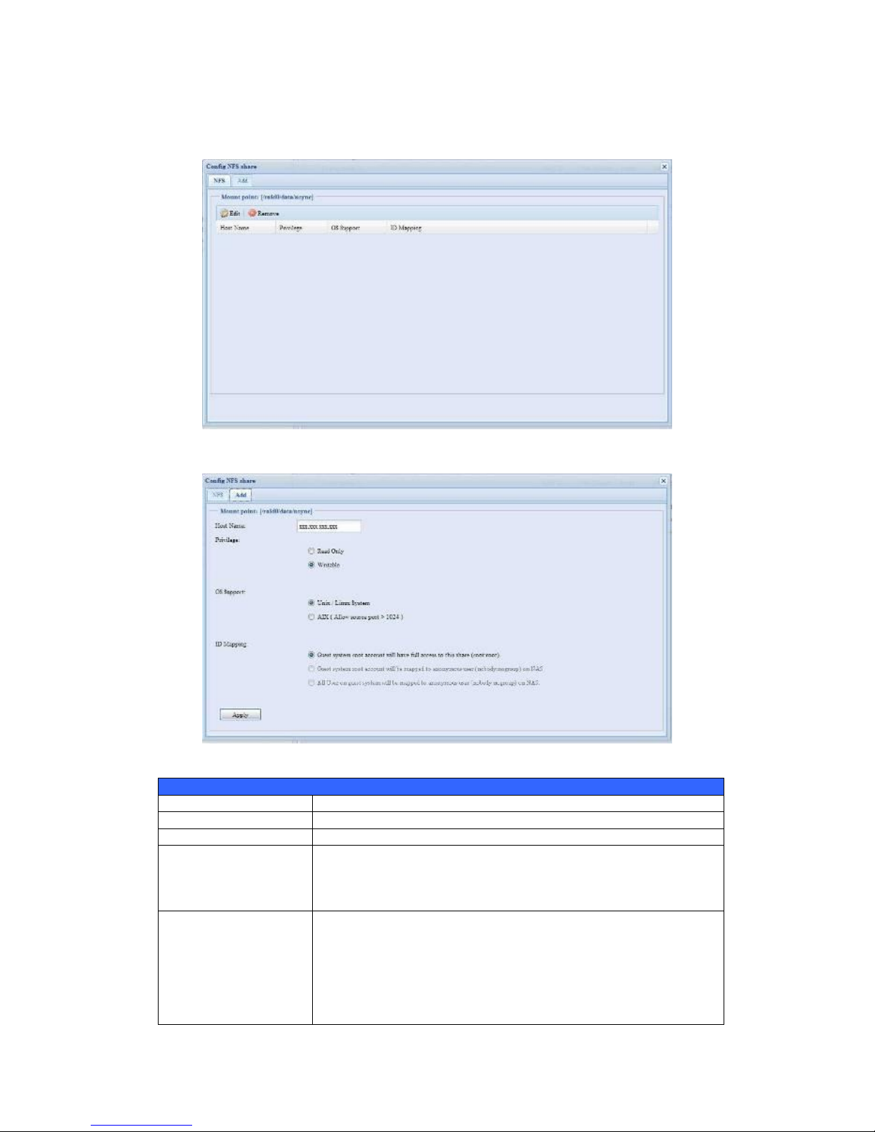
72
NFS Share
To allow NFS access to the share folder, enable the NFS Service, and then set up
hosts with access rights by clicking Add.
NFS Share
Item
Description
Hostname
Enter the name or IP address of the host
Privilege
Host has either read only or writeable access to the folder.
Guest System Support
There are two selections available:
Unix / Linux System
AIX (Allow source port > 1024)
Choose the one which best fits your needs.
IO Mapping
There are three selections available:
Guest system root account will have full access to this
share (root:root).
Guest system root account will be mapped to anonymous
user (nobody:nogroup) on NAS.
All user on guest system will be mapped to anonymous
user (nobody:nogroup) on NAS.
Page 73

73
Choose the one which best fits your needs.
Apply
Click to save your changes.
Folder and Sub-Folder Access Control List (ACL)
On the Folder screen, press
the ACL button, and the ACL
setting screen appears. This
screen allows you to
configure access to the
specific folder and
sub-folders for users and
groups. Select a user or a
group from the left hand
column and then choose
Deny, Read Only, or
Writable to configure their
access level. Press the Apply
button to confirm your
settings.
ACL setting
Item
Description
Deny
Denies access to users or groups who are displayed in this column.
Read Only
Provides Read Only access to users or groups who are displayed in
this column.
Writable
Provides Write access to users or groups who are displayed in this
column.
Recursive
Enable to inherit the access right for all its sub-folders.
To configure folder access, follow the steps below:
1. On the ACL screen, all network groups and users are listed in the left hand
column. Select a group or user from this list.
2. With the group or user selected, press one of the buttons from the three
access level columns at the top. The group or user then appears in that
column and has that level of access to the folder.
Page 74

74
3. Continue selecting groups and users and assigning them access levels using
the column buttons.
4. To remove a group or user from an access level column, press the Remove
button in that column.
5. When you are finished, press Apply to confirm your ACL settings.
To setup sub-folders ACL, click on ― ‖ symbol to extract sub folders list as screen
shot shows below. You may carry on with same steps as share level ACL setting.
The ACL screen also allows you to search for a particular user. To do this, follow the
steps below:
1. In the blank, enter the name of the user you would like to find.
2. From the drop down select the group you would like to search for the user in.
3. Click Search.
NOTE
If one user has belonged to more than one group but different privilege than
the priority Deny > Read Only > Writable
NOTE
The system will list up to 1,000 users from the chosen category. To narrow
your search, enter a search term in the blank provided.
NOTE
The ACL can be set for share and sub-folders level, not for files.
Page 75

75
ISO Mount
The ISO Mount feature is very useful tool from Thecus products. With it, users can
mount an ISO file and having export name to display all details from mounted ISO
file.
From the main menu, the ISO Mount feature is located under ―Storage‖. Please refer
the figure below for reference.
Select on the ISO mount function and you will have the screen shot appear as
following.
A. Add a ISO file
From the figure above, select ISO file from drop down share list.
After selection, system will bring up Mount table for further setting screen.
Page 76

76
To mount new ISO file, select from listed ISO file and input desired mounting name
into ―Mount as:‖ field. Click ―ADD‖ with confirmation to complete mounting ISO file.
Or without ―Mount as‖ ISO file export name input, system will automatic to give the
export name by ISO file name.
If left ―Mount as:‖ blink then system will create mount point by ISO file name.
After you have completed to add ISO then the page will displayed all mounted ISO
files,
Page 77

77
You could click ―Unmount‖ to eliminate mounted ISO file.
B. Using ISO
The mounted ISO file will be located same share folder with name giving. Please
refer the screen shot below.
ISO file ―image‖ has mounted as folder ―Image‖ you could see. The ISO file ―Thecus
01‖ without assign mounting name, system automatically has folder ―Thecus 01‖
created.
User and Group Authentication
The Thecus IP storage has built-in user database that allows administrators to
manage user access using different group policies. From the User and Group
Authentication menu, you can create, modify, and delete users, and assign them
to groups that you designate.
Page 78

78
Local User Configuration
From the Accounts menu, choose the User item, and the Local User
Configuration screen appears. This screen allows you to Add, Edit, and Remove
local users.
Local User Configuration
Item
Description
Add
Press the Add button to add a user to the list of local users.
Edit
Press the Edit button to modify a local user.
Remove
Press the Remove button to delete a selected user from the
system.
‧Add Users
1. Click on the Add button on Local User Configuration screen, and Local
User Setting screen appears.
2. On the Local User Setting screen, enter a name in the User Name box.
3. Enter a User ID number. If left blank, the system will automatically assign
one.
4. Enter a password in the Password box and re-enter the password in the
Confirm box.
5. Select which group the user will belong to. Group Members is a list of
groups this user belongs to. Group List is a list of groups this user does not
belong to. Use the << or >> buttons to have this user join or leave a group.
6. Press the Apply button and the user is created.
Page 79

79
‧Edit Users
1. Select an existing user from the Local User Configuration screen.
2. Click on the Edit button, and Local User Setting screen appears.
3. From here, you can enter a new password and re-enter to confirm, or use the
<< or >> buttons to have this user join or leave a group. Click the Apply
button to save your changes.
Remove Users
1. Select an existing user from the Local User Configuration screen.
NOTE
All users are automatically assigned to the ‗users‘ group.
Page 80

80
2. Click on Remove button and the user is deleted from the system.
Local Group Configuration
From the Accounts menu, choose the Group item, and the Local Group
Configuration screen appears. This screen allows you to Add, Edit, and Remove
local groups.
Local Group Configuration
Item
Description
Add
Press the Add button to add a user to the list of local groups.
Edit
Press the Edit button to modify a selected group from the system.
Remove
Press the Remove button to delete a selected group from the
system.
Add Groups
1. On the Local Group Configuration screen, click on the Add button.
2. The Local Group Setting screen appears.
3. Enter a Group Name.
Page 81

81
4. Enter a Group ID number. If left blank, the system will automatically assign
one.
5. Select users to be in this group from the Users List by adding them to the
Members List using the << button.
6. Click the Apply button to save your changes.
Edit Groups
1. On the Local Group Configuration screen, select a group name from the
list.
2. Press the Edit button to modify the members in a group.
3. To add a user into a group, select the user from the Users List, and press
the << button to move the user into the Members List.
4. To remove a user from a group, select the user from Members List, and
press the >> button.
5. Click the Apply button to save your changes.
Remove Groups
1. On the Local Group Configuration screen, select a group name from the
list.
2. Press Remove to delete the group from the system.
Page 82

82
Batch Create Users and Groups
The Thecus IP storage can also add users and groups in batch mode. This enables
you to conveniently add numerous users and groups automatically by importing a
simple comma-separated plain text (*.txt) file.
From the Accounts menu, click Batch Mgmt and the Batch Create Users and
Groups dialogue will appear. To import your list of users and groups, follow these
steps:
1. Click Browse… to locate your comma-separated text file.
The information in the text file should follow this format:
[USERNAME], [PASSWORD], [GROUP]
2. Click Open.
3. Click Import to begin the user list import.
Application Server
The Thecus IP storage supports printer server, and Tunes server. The integrated
Print Server allows you to share a single USB printer will all users on the network.
The Thecus IP storage provides activating the iTunes Server on the device. You will
Page 83
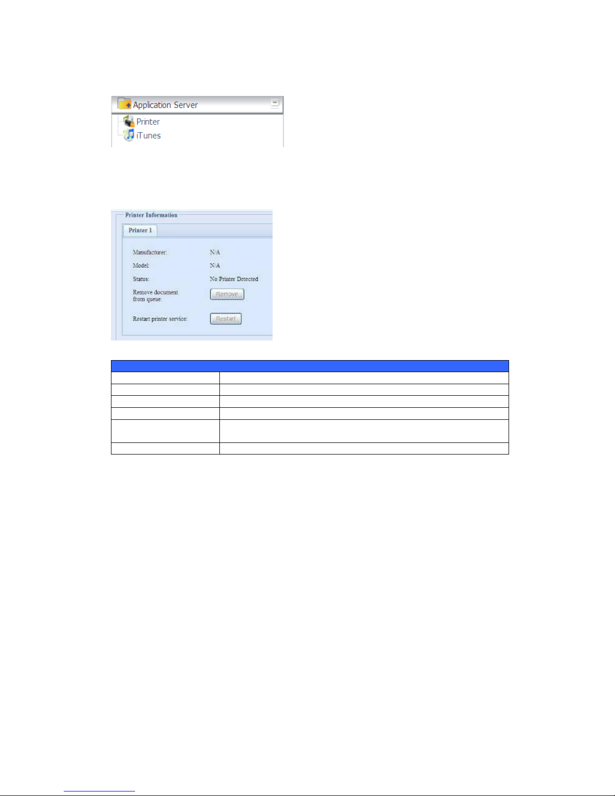
83
be able to play music files on this device with your iTunes client software directly.
The following section shows you how.
Printer Information
From the Application Server menu, choose the Printer item, and the Printer
Information screen appears. This screen provides the following information about
the USB printer connected to the USB port.
Printer Information
Item
Description
Manufacturer
Displays the name of the USB printer manufacturer.
Model
Displays the model of the USB printer.
Status
Displays the status of the USB printer.
Remove document
from Queue
Click to remove all documents from printer queue
Restart Printer service
Click to restart printer service
If a corrupt print job is sent to a printer, printing may suddenly fail. If your print jobs
seem to be locked up, pressing the Remove All Documents button to clear the
print queue may resolve the issue.
You can configure Thecus IP storage to act as a printer server. That way, all PCs
connected to the network can utilize the same printer.
Windows XP SP2
To set up the Printer Server in Windows XP SP2, follow the steps below:
1. Connect the USB printer to one of the USB ports (preferably the rear USB
ports; front USB ports can be used for external HDD enclosures).
2. Go to Start > Printers and Faxes.
3. Click on File > Add Printer.
4. The Add Printer Wizard appears on your screen. Click Next.
5. Select the ―A network printer, or a printer attached to another
computer‖ option.
Page 84

84
6. Select ―Connect to a printer on the Internet or on a home or office
network‖, and enter ―http://Thecus IP storage
IP_ADDRESS:631/printers/usb-printer‖ into the URL field.
7. Your Windows system will ask you to install drivers for your printer. Select
correct driver for your printer.
8. Your Windows system will ask you if you want to set this printer as ―Default
Printer‖. Select Yes and all your print jobs will be submitted to this printer by
default. Click Next.
9. Click Finish.
Windows Vista
To set up the Printer Server in Windows Vista, follow the steps below:
1. Open Printer Folder from the Control Panel.
2. Click the right mouse button in anywhere on the Printers folder and then
select Add Printer.
NOTE
• Not all USB printers are supported. Please check Thecus website for a list of
supported printers.
• Note that if a multi-function (all-in-one) printer is attached to the Thecus IP
storage, usually only the printing and fax functions will work. Other
features, such as scanning, will probably not function.
Page 85

85
3. Select Add a network, wireless or Bluetooth printer.
4. Select The printer that I want isn’t listed.
You can press The printer that I want isn’t listed to go into next page without
waiting for Searching for available printers to finish.
Page 86

86
5. Click Select a shared printer by name.
Type http://<Thecus_NAS>:631/printers/usb-printer in the box, where
<Thecus_NAS_IP> is the IP address of Thecus IP storage. Click Next.
6. Select or install a printer and then press OK.
If your printer model is not listed, please contact your printer manufacturer
for help.
7. Windows will attempt to connect to the printer.
8. You can choose to set this printer as the default printer by checking the Set
as the default printer box. Click Next to continue.
Page 87

87
9. Done! Click Finish.
iTunes® Server
With the built-in iTunes server capability, Thecus IP storage enables digital music to
be shared and played anywhere on the network!
From the Network menu, choose the iTunes item, and the iTunes Configuration
screen appears. You may enable or disable the iTunes Service from here. Once
enabled, enter correct information for each field and press Apply to save your
changes.
See the following table for detailed descriptions of each field:
Page 88

88
iTunes Configuration
Item
Description
iTunes
Enable or disable the iTunes Service.
Server Name
Name used to identify Thecus IP storage to iTunes clients.
Password
Enter password to control access to your iTunes music.
Rescan Interval
Rescan interval in seconds.
MP3 Tag Encode
Specify tag encoding for MP3 files stored in Thecus IP storage. All
ID3 tags will be sent out in UTF-8 format.
Once the iTunes service is enabled, Thecus IP storage will make all music located in
the Music folder available for iTunes-equipped computers on the network.
Module Management
Module Installation
From the Module Management menu, choose the Module Installation item and
the Module Management screen appears. From here, you can install separate
software modules to extend the functionality of your Thecus IP storage.
Auto Module Installation
Or choose the Auto Module Installation item and the available system Module
screen appears. The default to get module list is ―On-line‖ so if Thecus IP storage is
capable to connect to Internet then it will automatically link to Thecus official
website then list available modules. Please refer the screen shot below.
Page 89

89
The other way to have auto module installed is using universal CD shipped with
system. It has contained file ―modules.zip‖ which included all modules while system
shipped. Please refer the screenshot below.
Auto Module Source List
Item
Description
Installed
Status of module
Name
Module name
Version
The version of released version
Description
The description of module
Location
The module is either getting on-line or disk
Document
The available documentation of module
Action
To install module or deleted
p.s. If module list from on-line, then no delete option available
Rescan
Click to rescan from both on-line and disk
After click on ―Action‖ to install module, the module will be under list of Module
Installation. Please do ―Enable‖ to activate module usage.
System Module
The system module is officially provided by Thecus for new features added. The
module will list once it has been enabled from ―Module Installation‖.
NOTE
The modules list getting on-line of Thecus website will newly
than ―thecus.zip‖ from shipped CD. But the installation from
Thecus website could have unpredictable duration due to
bandwidth concern.
Page 90

90
‧User Module
The user module is reserved for Thecus fans to build up 3rd party functions in the
future.
Backup
There is a way to back up data with the Thecus IP storage.
Nsync(Rsync for N2200EVO/N4100EVO)
You can backup a share folder to another Native Rsync Server for safe keeping as
long as you have appropriate access right on that target.
If the files on your Thecus IP storage are lost for any reason, you can restore those
files from the target Native Rsync Server. To backup files regularly, you can set up
a scheduled task to run only once, daily, weekly, or monthly.
Under the Backup menu, click Nsync and the Nsync window appears.
Below is a description of each field:
Nsync
Item
Description
Add
Click to add a Nsync task
Edit
Click to Edit an Nsync task.
Restore
Restore share folder from an Nsync target.
Del
Click to delete an Nsync task. Backup files on Nsync target is also
deleted.
Task name
The name of your Nsync task.
Server
The IP address of your target server
Share folder
The share folder you would want to backup.
Last Time
The time when the last Nsync task was executed.
Last Status
The status of your last Nsync task.
Schedule
Schedule backup of your share folders.
Action
Administrator can run or stop an Nsync task by pressing the action
button.
Add Nsync Task
From the Nsync screen, click Add to display the Add Nsync Task screen.
Page 91

91
Add Nsync Task
Item
Description
Task Name
The name of your Nsync task.
Target Server
Manufacturer
Select replication to method, it has 1 options can choose from.
Native Rsync Server: Using rsync to replicate data to other Thecus
IP storage
Nsync Mode
Synchronize mode or Incremental mode .
Target Server IP
Address
The IP address of your target server.
Source Folder
The share folder you want to backup.
Authorized Username
on Target Server
The account name on the target server.
Password on Target
Server
The password for the username on the target server.
Test Connection
Click to check the connection to the Target Server.
Schedule
Enable or Disable schedule backup of your share folders.
Time
The time when the Nsync task will run.
Type
Select whether to run the Nsync task daily, weekly, or monthly.
Daily: input the time of day to execute Nsync task.
Weekly: input which day of the week to execute the task.
Monthly: decide which day of the month to execute the task.
Add
Press Add to submit your settings.
NOTE
Before starting an Nsync Task, make sure the target server‘s Nsync
Server is enabled.
NOTE
Using ―Native Rsync Server‖ to backup data to other Thecus NAS devices
needs to enable target server and setup a valid username and password
to grant access permission.
Page 92

92
Setting Up an Nsync Target on an Thecus IP storage Nsync Device
On the Nsync target server, the administrator of that server has to set up a user
account with a folder named ―nsync‖ and grant write access.
1. On the Nsync server, add a user for Nsync source (ex. nsyncsource1). For
instructions on how to add a user on the Thecus IP storage, see Chapter 4:
User and Groups Authentication> Local User Configuration > Add
Users.
2. On the Nsync server, grant that user (ex. nsyncsource1) write access to the
nsync folder. For instructions on how to set up a folder‘s ACL, see
Chapter 4: Storage management> Shore Folder> Folder Access
Control List (ACL).
3. Once this is done, the target server will start accepting Nsync tasks from
server using that ID and password.
‧
Setting Up an Nsync Target on another Device other than Thecus IP storage
If you selected ―Legacy FTP Server‖ when setting up your Nsync task, the Thecus IP
storage will use the FTP protocol to back up the share folder. On the external storage
device, make sure there is a folder named ―nsync‖, and the Auth ID has writable
permission in that folder.
‧
Designating Thecus IP storage as an Nsync Target
The Thecus IP storage can act as an Nsync server, enabling another Nsync-equipped
Thecus NAS at a remote location backup their files to this Thecus IP storage. From
the System Network menu, choose the Nsync Target item, and the Nsync
Target Server screen appears.
Nsync Target Server Setting
Item
Description
Nsync Target Server
Enable or Disable Nsync Target support.
NOTE
To enable Nsync task to go thru firewall, you have to open port TCP/1194 on
your firewall in both directions.
Page 93

93
Chapter 5: Using Thecus IP Storage
Overview
Once the Thecus IP storage is setup and operating, users on the network may
manage all varieties of digital music, photos, or files by simply using their web
browsers. To manage your personal files or access public files on the Thecus IP
storage, just enter its IP address into your browser (default IP address is
http://192.168.1.100), and you will be taken to the Thecus IP storage Login
page.
Login Page
To login to the system, enter your user name and password, and select Web Disk or
Photo server then click Login to log into the system. You will be taken to the
selected interface.
NOTE
Before proceeding, make sure that WebDisk Support or Secure WebDisk Support is
enabled in the Service Support screen in the system‘s Network menu. See Service
Support in Chapter 4: System Network >HTTP/Web Disk.
Page 94

94
Using WebDisk
(Does not apply to the N2200EVO/N4100EVO’ Web Disk)
The Thecus IP storage provides a WebDisk function that allows you to access the
system over the Internet from any browser.
1. In the Login page, type in the User ID and password that were previously set
for you in the Accounts menu. See
Chapter 4:User and Group Authentication > Local User Configuration.
2. The WebDisk page appears showing folders made currently available to you
via the Access Control List (ACL).
3. Click on a folder name to enter the folder.
4. The folder‘s page appears displaying files and folders. Click on a file to
download the file.
5. Buttons on the folder page allow you to create a new folder, upload files and
delete files in the folder.
6. To create a new folder within the current folder, press the New folder button.
When the screen appears enter a name for the folder. Press OK to create the
folder.
7. To upload a file from your computer to the current folder, press the New file
(upload) button. When the screen appears, press Browse and locate the file
to upload. Press OK and the file is uploaded to the current folder.
8. To delete a file or folder, select the file or folder‘s check box. Press the Delete
selected items button. You can also check the check box as the red circle
indicates to select all files and folders in this folder.
To access folders with access control, you must first login with a local user account.
For more information on how to setup user rights to the folders, please check
Chapter 4: Storage Management >Share Folder > Folder Access Control
List (ACL).
Page 95

95
Folder Page Button
Button
Description
List all directory trees per login user‘s privilege.
Browsing selected directory of its folders and files.
Go back to the web disk directory layer.
Re-load the current list.
Search files in the current web disk directory.
(Must input the complete file name.)
(new file/Directory)
Creates a new folder or directory.
(delete)
Deletes selected files or folders.
(Rename)
Rename a directory or file.
(download)
Download a file to current folder of your computer.
(upload)
Upload file from your computer to current web disk folder.
(Admin)
Change password and confirm new password.
(logout)
To logout of the web disk interface.
Show the files and folders in the directory.
Search files in the directory.
(You can only input some word string.)
Name
Displays the names of folders and files.
Size
Shows the size of folders and files.
Type
Displays the type of folders and files.
Page 96

96
Modified
Shows the time of most recent modification of folders and files.
owner
Owner of the file.
There is also the way by using right click button to
bring up contact windows as short cut to operate
what you needed.
Photo Server
(Does not apply to the N2200EVO/N4100EVO’ photo server)
Using the Photo Server, users can view and share photos, and even create their own
albums right on the Thecus IP storage.
You will see your own Photo Gallery and all public Photo Albums on the network.
To manage any picture files, you must first select the item by clicking the box then
enter user name and password to login photo server.
Page 97

97
Windows XP Publishing Wizard
There are many ways for a local user to upload pictures into their photo album.
Users of Windows XP can upload their pictures using the Windows XP Publishing
Wizard.
1. Click on the XP Publishing Wizard icon on top right corner.
2. The XP Web Publishing Wizard Client screen appears. Click on the link to
install the Publishing Wizard.
3. Windows XP will ask whether you want to run or save this file. Click Save to
save the register file.
4. Once the register file is installed, use the Windows file manager to browse
the folder that contains the picture you want to publish. On the left pane,
there will be an icon labeled ―Publish this folder to the Web‖.
Page 98
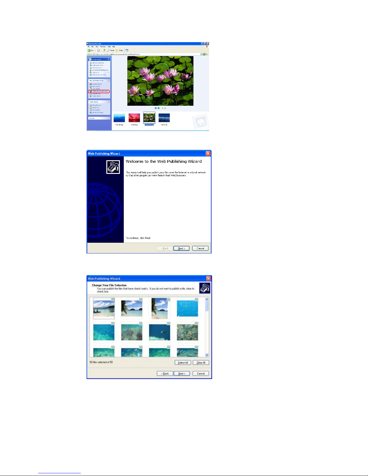
98
5. Click on this icon and Web Publishing Wizard will start.
6. Select the pictures you want to publish to the Photo Web Server by placing a
check mark on the top left hand corner of the picture. Click Next.
7. Your PC will start to connect to the Photo Web Server.
8. Select Thecus IP storage Photo Gallery Wizard to publish your pictures
to Thecus IP storage.
Page 99

99
9. Login into the Thecus IP storage with your local user name and password.
10. Create your album by entering an album name and clicking on the Create
Album button.
11. Select the album you want to upload your pictures to.
12. Confirm the target album.
Page 100

100
13. Windows will show you that the picture upload is in progress.
14. When the upload is finished, the Wizard will ask you whether if you want to
go to the website. Click Finish to go to your Photo Web Server.
15. Click on the user‘s icon to go to that user‘s album.
 Loading...