

Page 1

User’s Manual
N2520/N2560/N4520/N4560 Series
v6.2
Page 2

ii Copyright and Trademark Notice
Copyright and Trademark Notice
Thecus and other names of Thecus products are registered trademarks of Thecus Technology Corp.
Microsoft, Windows, and the Windows logo are registered trademarks of Microsoft Corporation.
Apple, iTunes and Apple OS X are registered trademarks of Apple Computers, Inc. All other
trademarks and brand names are the property of their respective owners. Specifications are subject
to change without notice.
Copyright © 2013 Thecus Technology Corporation. All rights reserved.
About This Manual
All information in this manual has been carefully verified to ensure its correctness. In case of an error,
please provide us with your feedback. Thecus Technology Corporation reserves the right to modify
the contents of this manual without notice.
Product name: Thecus N2520/N2560/N4520/N4560 Series
Manual Version: 6.2
Release Date: July, 2013
Limited Warranty
Thecus Technology Corporation guarantees all components of Thecus NAS products are thoroughly
tested before they leave the factory and should function normally under general usage. In case of
any system malfunctions, Thecus Technology Corporation and its local representatives and dealers
are responsible for repair without cost to the customer if the product fails within the warranty period
and under normal usage. Thecus Technology Corporation is not responsible for any damage or loss
of data deemed to be caused by its products. It is highly recommended that users conduct necessary back-up practices.
Check the functions that are available on your particular Thecus NAS model at:
http://www.thecus.com.
Page 3

iiiSafety Warnings
Safety Warnings
For your safety, please read and follow the following safety warnings:
Read this manual thoroughly before attempting to set up your Thecus IP storage.
¾
Your Thecus IP storage is a complicated electronic device. DO NOT attempt to re-Thecus IP storage is a complicated electronic device. DO NOT attempt to re- is a complicated electronic device. DO NOT attempt to re-
¾
pair it under any circ umstances. In the case of malfunction, turn o the power im-
mediately and have it repaired at a qualied service center. Contact your vendor for
details.
DO NOT allow anything to rest on the power cord and DO NOT place the power
¾
cord in an area where it can be stepped on. Carefully place connecting cables to
avoid stepping or tripping on them.
Your Thecus IP storage can operate normally under temperatures between 5°C and
¾
40°C, with relative humidity of 20% – 85%. Using Thecus IP storage under extreme
environmental conditions could damage the unit.
Ensure that the Thecus IP storage is provided with the correct supply voltage (AC
¾
100V ~ 240V, 50/60 Hz, 3A). Plugging the Thecus IP storage to an incorrect power
source could damage the unit.
Do NOT expose Thecus IP storage to dampness, dust, or corrosive liquids.
¾
Do NOT place Thecus IP storage on any uneven surfaces.
¾
DO NOT place Thecus IP storage in direct sunlight or expose it to other heat sourc-Thecus IP storage in direct sunlight or expose it to other heat sourc- in direct sunlight or expose it to other heat sourc-
¾
es.
DO NOT use chemicals or aerosols to clean Thecus IP storage. Unplug the power
¾
cord and all connected cables before cleaning.
DO NOT place any objects on the Thecus IP storage or obstruct its ventilation slots
¾
to avoid overheating the unit.
Keep packaging out of the reach of children.
¾
If disposing of the device, please follow your local regulations for the safe disposal
¾
of electronic products to protect the environment.
Page 4

iv Table of Contents
Table of Contents
Copyright and Trademark Notice. ...............................................ii
About This Manual. ......................................................................ii
Limited Warranty. ........................................................................ii
Safety Warnings. ..........................................................................iii
§Chapter 1: Introduction. ............................................................1
1.1 Overview. .........................................................................................1
1.2 Package Contents. ..........................................................................1
1.3 Front Panel . .....................................................................................2
1.4 Rear Panel. .......................................................................................4
§Chapter 2: Hardware Installation. ............................................6
§Chapter 3: System Administration. ..........................................8
3.1 Overview. .........................................................................................8
3.2 Web Administration Interface. .......................................................8
3.2.1 My Favorite. ...................................................................................................................9
3.2.2 Control Panel ................................................................................................................. 9
3.2.3 Message Bar. .................................................................................................................. 10
3.2.4 Logout. ............................................................................................................................ 10
3.2.5 Online Update Notication. .....................................................................................10
3.2.6 Language Selection. ................................................................................................... 11
3.3 System Management. .....................................................................11
3.3.1 General. ........................................................................................................................... 11
3.3.2 System/Service Status. ............................................................................................... 12
3.3.3 Hardware Information. .............................................................................................. 12
3.3.4 Logs. .................................................................................................................................12
3.3.5 Syslog Management. .................................................................................................. 13
3.3.6 System Monitor. ........................................................................................................... 14
3.3.7 Time: Setting system time . ......................................................................................17
3.3.8 Notication conguration. ....................................................................................... 17
3.3.9 Schedule Power On/O. ............................................................................................18
3.3.10 Administrator Password. ......................................................................................... 19
3.3.11 Cong Mgmt. ..............................................................................................................19
3.3.12 Factory Default. .......................................................................................................... 19
Page 5

vTable of Contents
3.3.13 Reboot & Shutdown. ................................................................................................ 20
3.3.14 File System Check. .................................................................................................... 20
3.3.15 Wake-Up On LAN (WOL). ........................................................................................ 22
3.3.16 SNMP Support (N4520/N4560 Only). .................................................................22
3.3.17 UI Login Function. ..................................................................................................... 22
3.3.18 Networking. ................................................................................................................23
3.4 Storage Management. ...................................................................24
3.4.1 Disks Information......................................................................................................... 24
3.4.2 RAID Information. ........................................................................................................ 26
3.4.3 NAS Stacking (N4520/N4560 Only). ......................................................................36
3.4.4 ISO Mount (N4520/N4560 Only). ............................................................................ 42
3.4.5 iSCSI (N4520/N4560 Only). ....................................................................................... 44
3.5 File Sharing/Privilege. .....................................................................52
3.5.1 ADS Support (N4520/N4560 Only). ....................................................................... 52
3.5.2 Local User Conguration. .......................................................................................... 53
3.5.3 Local Group Conguration. ...................................................................................... 55
3.5.4 Batch Users and Groups Creation. ......................................................................... 57
3.5.5 Share Folder. .................................................................................................................. 58
3.5.6 User Quota. .................................................................................................................... 63
3.5.7 User and Group Backup. ............................................................................................ 64
3.5.8 LDAP Support (N4520/N4560 Only). ..................................................................... 64
3.6 Network Service. .............................................................................66
3.6.1 Samba / CIFS. ...............................................................................................................66
3.6.2 AFP (Apple Network Setup). .................................................................................... 68
3.6.3 NFS Setup (N4520/N4560 Only). ............................................................................69
3.6.4 FTP . ..................................................................................................................................69
3.6.5 TFTP (N4520/N4560 Only). ....................................................................................... 70
3.6.6 WebService . ..................................................................................................................70
3.6.7 UPnP. ................................................................................................................................71
3.6.8 Bonjour Setting. ...........................................................................................................71
3.6.9 SSH. ..................................................................................................................................72
3.6.10 DDNS. ............................................................................................................................ 72
3.6.11 UPnP Port Management. ........................................................................................ 73
3.7 Application Server. .........................................................................75
3.7.1 iTunes® Server (Built in). ............................................................................................. 75
3.7.2 Add-on Ocial Applications. ...................................................................................75
Page 6

vi
Table of Contents
3.7.3 Module Installation. .................................................................................................... 75
3.7.4 NAS Application. .......................................................................................................... 76
3.8 Backup. ............................................................................................76
3.8.1 Rsync Target Server. .................................................................................................... 76
3.8.2 Data Guard (Remote Backup). ................................................................................. 77
3.8.3 Data Guard (Local Backup). ...................................................................................... 88
3.8.4 ACL Backup and Restore. .......................................................................................... 102
3.8.5 Data Burn. ...................................................................................................................... 104
3.9 External Devices. .............................................................................107
3.9.1 Printers. ...........................................................................................................................107
3.9.2 Uninterrupted Power Source. .................................................................................. 112
Appendix A: Customer Support. .................................................113
Appendix B: RAID Basics. ............................................................114
Appendix C: Active Directory Basics. .........................................117
Appendix D: Licensing Information. ...........................................118
Page 7

1
Chapter 1: Introduction
Chapter 1: Introduction§
Overview1.1
Thank you for choosing the Thecus IP Storage Server. The Thecus IP storage is an easy-to-use storage
server that allows a dedicated approach to storing and distributing data on a network. Data reliability is ensured with RAID features that provide data security and recovery—over multiple Terabyte of
storage are available using RAID 5 and RAID 6. Gigabit Ethernet ports enhance network efficiency, allowing Thecus IP storage to take over fi le management functions, increase application and data shar-Thecus IP storage to take over fi le management functions, increase application and data shar- IP storage to take over fi le management functions, increase application and data shar-IP storage to take over fi le management functions, increase application and data shar- to take over file management functions, increase application and data sharing and provide faster data response. The Thecus IP storage offers data mobility with a disk roaming
feature that lets you swap working hard drives for use in other Thecus IP storage, securing the con- Thecus IP storage, securing the con-, securing the continuity of data in the event of hardware failure. The Thecus IP storage allows data consolidation and
sharing between Windows (SMB/CIFS), UNIX/Linux, and Apple OS X environments. The Thecus IP
storage’s user-friendly GUI supports multiple Languages.
Package Contents1.2
N2520/N2560•
The Thecus IP storage should contain the following common items:
System Unit x1
QIG (Quick Installation Guide) x1
CD-Title (Universal CD) x1
Ethernet Cable x1
Accessory bag x1
HDD Compatibility list Card x1
Multiple Language Warranty Card x1
Power adapter x1
Power cord x1
N4520/N4560•
The Thecus IP storage should contain the following common items:
System Unit x1
QIG (Quick Installation Guide) x1
CD-Title (Universal CD) x1
Ethernet Cable x1
Accessory bag x1
HDD Compatibility list Card x1
Multiple Languages Warranty Card x1
Power cord x1
Please check to see if your package is complete. If you find that some items are missing, contact your
dealer.
Page 8

2
Chapter 1: Introduction
Front Panel 1.3
N2520/N2560:•
The Thecus N2520/N2560’s front panel shows the device’s indicators and hard disk install slots:
Front Panel
Item Description
1. System status
Blinking white: Diagnostic mode kick-in
Solid white: Diagnostic completed
2. HDD1 LED
Blinking white: HDD activity
Red: HDD failure
3. HDD2 LED
Blinking white: HDD activity
Red: HDD failure
4. LAN LED
Solid white: LAN Cable link
Blinking : Network activity
5. USB LED
Solid white: Installed
Blinking white: USB copy activity
Solid Red: USB copy failure
6. USB Copy Button Copies USB storage contents to N2520/N2560.
7. Power Button/LED
Power the N2520/N2560 on/off.
Solid blue: System ready
Blinking blue: Power on process
8. USB Port USB 3.0 port for compatible USB devices, such as digital cameras, USB disks, and USB printers.
9. Thecus Logo LED
Solid white: System ready
Blinking white: System booting
Page 9

3
Chapter 1: Introduction
N4520/N4560:•
The Thecus N4520/N4560 front panel shows the device’s indicators, system information and hard
disk trays:
Front Panel
Item Description
1. Power LED Solid blue: Power on
2. System status
Blinking orange: Diagnostic mode kick-in
Solid orange: Diagnostic completed
3. LAN LED Green : Network activity
4. System Failure Red on while diagnostic test failed.
5. USB Port USB 3.0 port for compatible USB devices, such as digital cameras, USB disks, and USB printers.
6. Power Button Powers the N4520/N4560 on/off.
7. Up Button Select the previous configuration settings option.
8. Down Button USB copy confirmation display.
9. Enter Enter the selected menu option, sub-menu, or parameter setting.
10. Escape Escape and return to the previous menu.
11. LCD Display Displays current system status and warning messages.
12. HDD Tray Four HDD trays support 4x 3.5" or 4 x 2.5” HDDs
Page 10

4
Chapter 1: Introduction
Rear Panel1.4
N2520/N2560:•
The N2520/N2560 rear panel features ports and connectors.
Back Panel
Item Description
1. System Fan System fan that exhausts heat from the unit.
2. HDMI For Video/Audio out
3. SPDIF For Audio out
4. LAN Port LAN port for connecting to an Ethernet network through a switch or a router.
5. USB Port USB 2.0 port for compatible USB devices, such as digital cameras, USB disks, and USB printers.
6. Power Connector Connect the included power cords to this connector.
7. Reset Button Resets the N2520/N2560.
Pressing and holding the Reset button on the back for 5 seconds will reset your network
setting and password, and turn off Jumbo Frame Support.
Page 11

5
Chapter 1: Introduction
N4520/N4560:•
The N4520/N4560 rear panel features ports and connectors.
Back Panel
Item Description
1. System Fan System fan that exhausts heat from the unit.
2. USB Ports USB 2.0 port for compatible USB devices, such as digital cameras, USB disks, and USB printers.
3. LAN Port LAN port for connecting to an Ethernet network through a switch or router
4. Reset Button Resets the N4520/N4560.
Pressing and holding the Reset button on the back for 5 seconds will reset your network
setting and password, and turn off Jumbo Frame Support.
5. HDMI For Video/Audio out
6. SPDIF For Audio out
7. Power Connector Connect the included power cords to this connector.
Page 12

6
Chapter 2: Hardware Installation
Chapter 2: Hardware Installation§
Overview2.1
Your Thecus IP storage is designed for easy installation. To help you get started, the following chapter
will help you quickly get your Thecus IP storage up and running. Please read it carefully to prevent
damaging your unit during installation.
Before You Begin2.2
Before you begin, be sure to take the following precautions:
Read and understand the Safety Warnings outlined in the beginning of the manual.1.
If possible, wear an anti-static wrist strap during installation to prevent static discharge from 2.
damaging the sensitive electronic components on the Thecus IP storage.
Be careful not to use magnetized screwdrivers around the Thecus IP storage’s electronic com-Thecus IP storage’s electronic com-’s electronic com-s electronic com- electronic com-3.
ponents.
Cable Connections2.3
To connect the Thecus IP storage product to your network, follow the steps below:
Connect an Ethernet cable from your network to the LAN port on the back panel of the 1.
Thecus IP storage.
N2520/N2560 LAN port
S
N4520/N4560 LAN port
S
Connect the provided power cord into the universal power socket on the back panel. Plug 2.
the other end of the cord into a surge protector socket.
N2520/N2560 power socket
S
N4520/N4560 power socket
S
Page 13

7
Chapter 2: Hardware Installation
Press the power button on the Front Panel to boot up the Thecus IP storage. 3.
N2520/N2560 power button
S
N4520/N4560 power button
S
Page 14

8
Chapter 3: System Administration
Chapter 3: System Administration§
Overview3.1
The Thecus IP storage provides an easily accessible Web Administration Interface. With it, you can
configure and monitor the Thecus IP storage anywhere on the network.
Web Administration Interface3.2
Make sure your network is connected to the Internet. To access Thecus IP storage Web Administra-Thecus IP storage Web Administra- Web Administra-
tion Interface:
Type the Thecus IP storage IP address into your 1.
browser. (Default IP address can be found through
IntelligentNAS utility or LCD panel (N4520/N4560
only))
Login to the system using the administrator user name and password. The factory defaults 2.
are:
User Name: admin
Password: admin
Once you are logged in as an administrator, the disclaimer page will appear as below. Please
click the check box if you do not want to have this page displayed during the next login.
Following the disclaimer page, you will see the Web Administration Interface. From here, you
can configure and monitor virtually every aspect of the Thecus IP storage from anywhere on
the network.
Page 15

9
Chapter 3: System Administration
My Favorite3.2.1
The user interface with “My Favorite” shortcut allows the user to designate often used items and have
them display on the main screen area. The figure below displays system favorite functions.
Administrators can add or remove favorite functions to My Favorites by right clicking the mouse on
the menu tree.
Control Panel 3.2.2
The Control Panel is where you will find all of the information screens and system settings of Thecus
IP storage.
Control Panel
Item Description
System Management Current system status of the Thecus IP storage.
Storage Information and settings for storage devices installed into the Thecus IP storage.
File Sharing / Privilege Allows configuration of users and groups.
Network Service To setup varies protocols which has supported by system
Application Server Application based program for system build-in, additional installed from official or 3rd party.
Backup Category of Backup Features setup of the Thecus IP storage.
External Devices Setting for devices where has installed through external interface such as USB
In the following sections, you will find detailed explanations of each function, and how to configure
your Thecus IP storage.
Page 16

10
Chapter 3: System Administration
Message Bar3.2.3
You can get quick information about your system status by moving your mouse over these icons.
Message Bar
Item Status Description
RAID Information.
Display the status of created RAID volume. Click to go to RAID information page as
short cut.
Disks Information.
Display the status of disks installed in the system. Click to go to Disk information
page as short cut.
Network.
Green: Connection to the network is normal.
Red: abnormal connection to the network
Logout3.2.4
Click to logout Web Administration Interface.
Online Update Notication3.2.5
When there is a new update for system files or applications, the system will notify you through the
admin UI and also send an email. Click on the flashing icon then the system will link you directly to
the associated page.
Page 17

11
Chapter 3: System Administration
Language Selection3.2.6
The Thecus IP storage supports multiple Languages, including:
English
Japanese
Traditional Chinese
Simplified Chinese
French
German
Italian
Korean
Spanish
Russian
Polish
Portuguese
On the menu bar, click Language and the selection list ap-selection list ap- list ap-list ap-appears. This user interface will switch to the selected language for Thecus IP storage.
System Management3.3
Information provides viewing on current Product info, System Status, Service Status and Logs.
The menu bar allows you to see various aspects of the Thecus IP storage. From here, you can discov-Thecus IP storage. From here, you can discov-. From here, you can discover the status of the Thecus IP storage, and also other details.
General3.3.1
Once you login, you will first see the basic system Information screen providing Manufacturer,
Product No., Firmware Version, and System Up Time information.
General
Item Description
Manufacturer Displays the name of the system manufacturer.
Product No. Shows the model number of the system.
Firmware version Shows the current firmware version.
Up time Displays the total run time of the system.
Page 18

12
Chapter 3: System Administration
System/Service Status3.3.2
From the System Management category,, choose the Status item, System Service Status and HW Sta-tatus item, System Service Status and HW Sta- item, System Service Status and HW Sta-Service Status and HW Sta-and HW Sta- HW Sta- Status screens appear. These screens provide basic system and service status information.
Hardware Information3.3.3
From the System Management category,, choose the Hardware Information item and the system will
display the related HW details for the associated model. Below is an example of the information for a
Thecus N2520.
Logs3.3.4
From the System Management category, choose the System Logs item and the System Logs screen
appears. This screen shows a history of system usage and important events such as disk status, network information, and system booting. See the following table for a detailed description of each
item:
See the following table for a detailed description of each item:
System Logs
Item Description
All
Provides all log information including system messages, warning messages and er-system messages, warning messages and er-warning messages and error messages.
INFO Records information about system messages.
Page 19

13
Chapter 3: System Administration
WARN Shows only warning messages.
ERROR Shows only error messages.
Download All Log File Export all logs to an external file.
Truncate All Log File Clear all log files.
The number of lines per page Specify desired number of lines to display per page.
Sort Ascending Shows logs by date in ascending order.
Sort Descending Shows logs by date in descending order.
|<< < > >>| Use the forward ( > >>| ) and backward ( |<< < ) buttons to browse the log pages.
Re-loading logs.
Syslog Management3.3.5
Generates system log to be stored locally or remotely, it also can be chose to act as syslog server for
all other devices.
These messages are stored on your NAS in: Nsync > log> messages.
Information can be obtained in two ways: locally and remotely.
Conguration with syslog server:• Configuration with syslog client and •
target to store locally:
Conguration with syslog client and target to store remotely:•
See the following table for a detailed description of each item:
Syslog Management
Item Description
Syslog Daemon Enable/Disable syslog daemon.
Page 20

14
Chapter 3: System Administration
Syslog service
If Server has been selected then associated syslog folder will be used to store all system logs from other
NAS devices which has assigned this system for syslog server as well as syslog of this server unit. It can be
seen from associated syslog folder with files “error”, “Information” and “warning”.
If client has been selected then “Local” or “Remotely” can be choose.
Tar get
Choose Local, all system logs will be stored in an associated syslog folder filled in from next filed. And
the syslog folder will have file “messages” to store all system logs. If Remotely has been selected, a syslog
server is needed and an IP address is required.
Syslog folder
Select from a drop down share list, all of the system logs will be stored on it. This syslog folder is applied to
“syslog server” or “syslog client” with “local” selected.
Log Level The user can choose from 3 different levels. “All”, “Warning/Error” or “Error”.
Remote IP Address Input the syslog server IP address if choose to store syslog info remotely.
System Monitor3.3.6
The system monitor is capable to monitor system status including CPU/memory utilization, network
throughput and on-line user list in various protocols.
To monitor system status, simply click on “System Monitor” from the tree menu and the screen will
appear as below.
It is divided into 4 sections. Each section can be modified to monitor specific items by using the drop
down list from the “Monitors” tab, simply click on the items you would like to monitor. From each
section, you can also choose to display the information graphically by selecting “Graphic” or by plain
text mode by selecting “Details”.
Only 2 sections can be set in graphic mode at the same time.
If graphic mode is chosen, 3 minutes of information is displayed on the x-axis. A resume of the infor-is chosen, 3 minutes of information is displayed on the x-axis. A resume of the infor- chosen, 3 minutes of information is displayed on the x-axis. A resume of the infor-n, 3 minutes of information is displayed on the x-axis. A resume of the infor-, 3 minutes of information is displayed on the x-axis. A resume of the infor- 3 minutes of information is displayed on the x-axis. A resume of the infor-. A resume of the infor- A resume of the information is displayed by dragging the mouse over the graphic at a specific time. See example below:
Page 21

15
Chapter 3: System Administration
For the on-line users list, system monitor will display the on-line users and the share folder they have
visited.
System Monitor
Item Description
Save Layout Saving selected monitoring items. Layout will remain the same for future visits.
Reset Layout Set back to default monitoring settings and layout.
History Click on this check box and system monitor will write the monitoring history to a designate path in
the RAID volume.
Lock Layout All of the monitoring items are fixed and cannot be changed. Click again to unlock it.
If the History has been enabled, click on and system monitor will display the history
with different period for selection.
Page 22

16
Chapter 3: System Administration
Page 23

17
Chapter 3: System Administration
Time: Setting system time 3.3.7
From the System Management category, choose the Time item and the Time screen appears. Set the
desired Date, Time, and Time Zone. You can also elect to synchronize the system time on Thecus IP
storage with an NTP (Network Time Protocol) Server.
See the following table for a detailed description of each item:
Time
Item Description
Date Sets the system date.
Time Sets the system time.
Time Zone Sets the system time zone.
NTP Service Select Enable to synchronize with the NTP server.
Select Disable to close the NTP server synchronization.
Sync with external NTP
Server
Select YES to allow Thecus IP storage to synchronize with an NTP server of your choice. Press Apply
to change.
Notication conguration3.3.8
From the System Management category, choose the Notifi cation item, and the Notifi cation Confi gu-System Management category, choose the Notifi cation item, and the Notifi cation Confi gu-, choose the Notification item, and the Notification Configuration screen appears. This screen lets you have Thecus IP storage notify you in case of any system
malfunction. Press Apply to confirm all settings. See following table for a detailed description of each
item.
Notication Conguration
Item Description
Beep Notification Enable or disable the system buzzer that beeps when a problem occurs.
Email Notification Enable or disable email notifications of system problems.
Authentication Type Select the SMTP Server account authentication type.
SMTP Server Specifies the hostname/IP address of the SMTP server.
Port Specifies the port to send outgoing notification emails.
SMTP Account ID Set the SMTP Server Email account ID.
Account Password Enter a new password.
Log Level Select the log level to send the e-mail out.
Sender’s E-mail Address Set senders email address to send email notifications.
Receiver’s E-mail Address
(1,2,3,4)
Add one or more recipient’s email addresses to receive email notifications.
Page 24

18
Chapter 3: System Administration
Schedule Power On/O3.3.9
Using the Thecus IP storage System Management, you can save energy and money by scheduling
the Thecus IP storage to turn itself on and off during certain times of the day.
From the System Management category, choose the Schedule Power On/Off item and the Schedule
Power On/Off screen appears.
To designate a schedule for the Thecus IP storage to turn on and off, first enable the feature by
checking the Enable Schedule Power On/Off checkbox.
Then, simply choose an on and off time for each day of the week.
Finally, click Apply to save your changes.
Example - Monday: On: 8:00; O: 16:00
System will turn on at 8:00 AM on Monday, and off at 16:00 on Monday. System will turn on for the
rest of the week.
If you choose an on time, but do not assign an off time, the system will turn on and remain on until a
scheduled off time is reached, or if the unit is shutdown manually.
Example - Monday: On: 8:00
System will turn on at 8:00 AM on Monday, and will not shut down unless powered down manually.
You may also choose two on times or two off times on a particular day, and the system will act accordingly.
Example - Monday: O: 8:00; O: 16:00
System will turn off at 8:00 AM on Monday. System will turn off at 16:00 PM on Monday, if it was on. If
the system was already off at 16:00 PM on Monday, system will stay off.
Page 25

19
Chapter 3: System Administration
Administrator Password3.3.10
From the System Management category, choose the Administrator Password item and the Change
Administrator Password screen appears. Enter a new password in the New Password box and confirm your new password in the Confirm Password box. Press Apply to confirm password changes.
See the following table for a detailed description of each item.
Change Administrator
Item Description
New Password Type in a new administrator password.
Confirm Password Type the new password again to confirm.
Apply Press this to save your changes.
Cong Mgmt3.3.11
From the System Management category, choose the Config Mgmt item and the System Configuration Download/Upload screen appears. From here, you can download or upload stored system con- system con-system configurations.
See the following table for a detailed description of each item.
System Conguration Download/Upload
Item Description
Download Save and export the current system configuration.
Upload Import a saved configuration file to overwrite the current system configuration.
Backing up your system conguration is a great way to ensure that you
can revert to a working conguration when you are experimenting with
new system settings.
The system configuration you have backed up can only be restored
in the same firmware version. The backup details exclude user/group
accounts.
Factory Default3.3.12
From the System Management category, choose the Factory Default item and the Reset to Factory
Default screen appears. Press Apply to reset Thecus IP storage to factory default settings.
Page 26

20
Chapter 3: System Administration
Resetting to factory defaults will not erase the data stored in the hard
disks, but WILL revert all the settings to the factory default values
Reboot & Shutdown3.3.13
From the System Management category, choose Reboot & Shutdown item, and the Shutdown/Reboot System screen appears. Press Reboot to restart the system or Shutdown to turn the system off.
File System Check3.3.14
The File System Check allows you to perform a check on the integrity of your disks’ file system. Under
the System Management category, click File system Check and the File System Check prompt ap- system Check and the File System Check prompt ap-system Check and the File System Check prompt ap-em Check and the File System Check prompt ap-m Check and the File System Check prompt appears.
To perform a file system check, click Apply.
Once clicked, the following prompt will appear:
Click Yes to reboot the system.
Once the system has rebooted, you will be returned to the File System Check prompt. There you will
see the available RAID volumes to run the file system check. Check the desired RAID volumes and
click Next to proceed with the file system check. Click Reboot to reboot without running the check.
Page 27

21
Chapter 3: System Administration
Once you click Next, you will see the following screen:
Click Start to begin the file system check. Click Reboot to reboot the system.
When the file system check is running, the system will show 20 lines of information until it is complete. Once complete, the results will be shown at the bottom.
The system must be rebooted before Thecus IP storage can function
normally after le system check completes.
Page 28

22
Chapter 3: System Administration
Wake-Up On LAN (WOL)3.3.15
The Thecus IP storage has the ability to be awoken from sleep mode via LAN port.
From the System Management category, choose the WOL item, and the Wake-up On LAN screen appears. From here, you can Enable or Disable.
SNMP Support (N4520/N4560 Only)3.3.16
From the System Management category, choose the SNMP item and the SNMP Support screen ap-SNMP item and the SNMP Support screen ap- item and the SNMP Support screen ap-SNMP Support screen ap- screen appears. You could enable the SNMP function and filled in the related information in each fields. With
the SNMP management software, you can get other system’s basic information.
From the System Management category, choose the SNMP item, and the SNMP Support screen ap-SNMP item, and the SNMP Support screen ap- item, and the SNMP Support screen ap-SNMP Support screen ap- screen appears. From here, you can Enable or Disable.
UI Login Function3.3.17
Adjusts UI Login Configuration settings, you can enable/disable the Web Disk, Photo Server and
modules functions, according to your needs.
Page 29

23
Chapter 3: System Administration
Networking3.3.18
From the System Management category, choose Networking, and the Networking Configuration
screen appears. This screen displays the network parameters of the global setting and available
network connection. You may change any of these items and press Apply to confirm your settings.
See a description of each item in the following table:
Network Conguration (Global parameter)
Item Description
Host name Host name that identifies the Thecus IP storage on the network.
Domain name Specifies the domain name of Thecus IP storage.
WINS Server
To set a server name for NetBIOS computer.
DNS Mode
Select the DNS server is coming from DHCP server or manual input. A total of 3 DNS
servers can be input. If the DNS setting is chosen from DHCP server, then it will refer to
WAN/LAN1 port.
DNS Server 1,2,3
Domain Name Service (DNS) server IP address.
Network Conguration (NIC port)
Link speed Display associated NIC port link speed.
Link status Display associated NIC port link status.
MAC address MAC address of the network interface.
Jumbo Frame Support Enable or disable Jumbo Frame Support of associate interface on your Thecus IP storage.
IPv4/IPv6 Click to enable IPv4/IPv6 for TCP/IP. The default is IPv4 enabled.
Mode It can choose a static IP or Dynamic IP.
IP IP address of associate NIC interface.
Netmask/Prefix Length Input netmask for IPv4 and Prefix length for IPv6.
Gateway Gateway for associate NIC.
Default gateway It can be chosen from a drop down list of default gateway that’s been used for the Thecus IP
storage.
Only use Jumbo Frame settings when operating in a Gigabit •
environment where all other clients have Jumbo Frame Setting
enabled.
Proper DNS setting is vital to networks services, such as SMTP and •
NTP.
Page 30

24
Chapter 3: System Administration
Most faster Ethernet (10/100) Switches/Routers do not support Jumbo
Frame and will not be able to connect to your Thecus NAS after Jumbo
Frame is turned on.
Storage Management3.4
The Storage menu displays the status of storage devices installed in the Thecus IP storage. It includes
storage configuration options such as RAID and disk settings, iSCSI (N4520/N4560) and ISO Mount
(N4520/N4560).
Disks Information3.4.1
From the Storage menu, choose the Disk Information item and the Disk Information screen appears.
From here, you can see various installed hard disks. The disk slot position will appear if the mouse is
moved over the installed disk.
The screen shot below is just an example from a Thecus IP Storage.
The disk slots number can range from 1,2 to 4 slots depending on the
model of Thecus IP storage. Also it will list the disk info of JBOD devices if
applicable.
Disks Information
Item Description
Disk No. Indicates disk location.
Capacity Shows the SATA hard disk capacity.
Model Displays the SATA hard disk model name.
Firmware Shows the SATA hard disk firmware version.
Bad Block scan Yes to start scan Bad Block.
Page 31
25
Chapter 3: System Administration
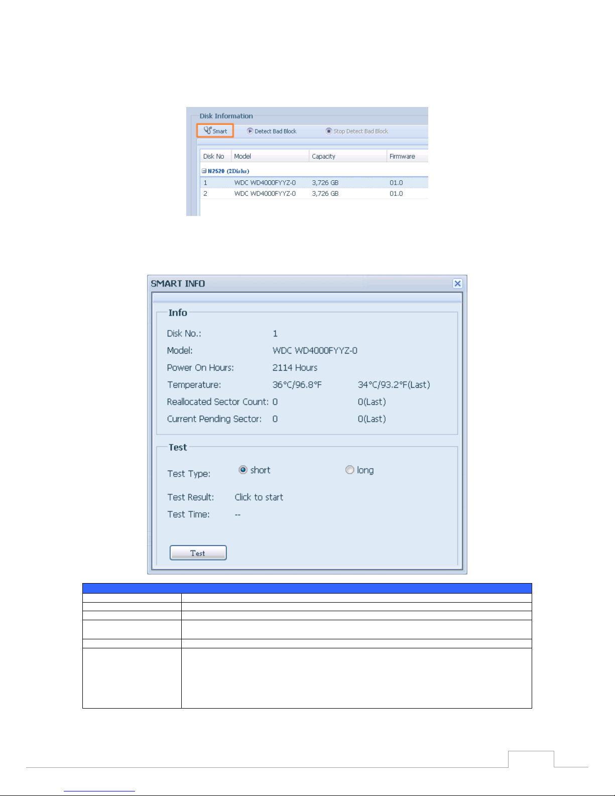
S.M.A.R.T. Information•
On the Disk Information screen, select a disk then click on “Smart” to list the S.M.A.R.T. info of the
associated disk.
You may also perform a disk SMART test; simply click “Test ” to start the SMART test. The result is only
for reference and the system will not take any action from its results.
S.M.A.R.T. Information
Item Description
Tray Number Tray the hard disk is installed in.
Model Model name of the installed hard disk.
Power ON Hours Count of hours in power-on state. The raw value of this attribute shows total count of hours (or min-
utes, or seconds, depending on manufacturer) in power-on state.
Temperature Celsius The current temperature of the hard disk in degrees Celsius.
Reallocated Sector Count Count of reallocated sectors. When the hard drive finds a read/write/verification error, it marks this sec-
tor as "reallocated" and transfers data to a special reserved area (spare area).
This process is also known as remapping and "reallocated" sectors are called remaps. This is why, on a
modern hard disks, you cannot see "bad blocks" while testing the surface - all bad blocks are hidden in
reallocated sectors. However, the more sectors that are reallocated, the more a decrease (up to 10% or
more) can be noticed in disk read/write speeds.
Page 32

26
Chapter 3: System Administration
Current Pending Sector
Current count of unstable sectors (waiting for remapping). The raw value of this attribute indicates the
total number of sectors waiting for remapping. Later, when some of these sectors are read successfully,
the value is decreased. If errors still occur when reading sectors, the hard drive will try to restore the
data, transfer it to the reserved disk area (spare area), and mark this sector as remapped. If this attribute
value remains at zero, it indicates that the quality of the corresponding surface area is low.
Test Type Set short or long time to test.
Test Result Result of the test.
Tes t T im e Total time of the test.
Bad Block Scan•
On the Disk Information screen, select a disk then click on “Detect Bad Block” to perform bad block
scan of the associated disk. The result is only for reference and the system will not take any action
from its results.
The bad block scan can be terminated by clicking on “Stop Detect Bad Block”.
RAID Information3.4.2
From the Storage menu, choose the RAID Management item and the RAID Management screen appears.
This screen lists the RAID volumes currently residing in the Thecus IP storage. From this screen, you
can get information about the status of your RAID volumes, as well as the capacities allocated for
data.
RAID Information
Item Description
Master RAID The RAID volume currently designated as the Master RAID volume.
ID ID of the current RAID volume.
NOTE: All RAID IDs must be unique.
Page 33

27
Chapter 3: System Administration
RAID Level Shows the current RAID configuration.
Status Indicates status of the RAID. Can read either Healthy, Degraded, or Damaged.
Disks Used Hard disks used to form the current RAID volume.
Total Capacity Total capacity of the current RAID.
Data Capacity Indicates the used capacity and total capacity used by user data.
Create a RAID •
On the RAID Information screen, press the Create button to go to the RAID Volume Creation screen.
In addition to RAID disk information and status, this screen lets you make RAID configuration settings.
Using Create RAID, you can select stripe size, choose which disks are RAID disks or the Spare Disk. .
RAID Congurations
Item Description
Disk No. Number assigned to the installed hard disks.
Capacity (MB) Capacity of the installed hard disks.
Model Model number of the installed hard disks.
Status Status of the installed hard disks.
Used If this is checked, current hard disk is aalready part of a RAID volume.
Spare If this is checked, current hard disk is designated as a spare for a RAID volume.
Master RAID Check a box to designate this as the Master RAID volume. See the NOTE below for more information.
Stripe Size This sets the stripe size to maximize performance of sequential files in a storage volume. Keep the 64K setting
unless you require a special file storage layout in the storage volume. A larger stripe size is better for large files.
Data Percentage The percentage of the RAID volume that will be used to store data.
Create Press this button to configure a file system and create the RAID storage volume.
To create a RAID volume, follow the steps below:
On the RAID Information screen, clicks create.1.
On the RAID Configuration screen, set the RAID storage space as JBOD, RAID 0, RAID 1, RAID 5, 2.
RAID 6 or RAID 10 (depends on model)— see Appendix B: RAID Basics for a detailed descrip- or RAID 10 (depends on model)— see Appendix B: RAID Basics for a detailed descrip- (depends on model)— see Appendix B: RAID Basics for a detailed descrip-(depends on model)— see Appendix B: RAID Basics for a detailed descrip-s on model)— see Appendix B: RAID Basics for a detailed descrip- on model)— see Appendix B: RAID Basics for a detailed descrip-— see Appendix B: RAID Basics for a detailed description of each.
Page 34

28
Chapter 3: System Administration
Specify a RAID ID. 3.
If this RAID volume is meant to be the Master RAID volume, tick the Master RAID checkbox.4.
In a multiple RAID conguration, one RAID volume must be designated
as the Master RAID volume. The Master RAID volume will store all
installed modules. If the Master RAID is changed to another location
(i.e. assigning volume 2 to be the Master RAID volume after volume 1
had been previously assigned), then all modules must be reinstalled.
In addition, all system folders that were contained on the Master RAID
volume will be invisible. Reassigning this volume to be the Master RAID
will make these folders visible again.
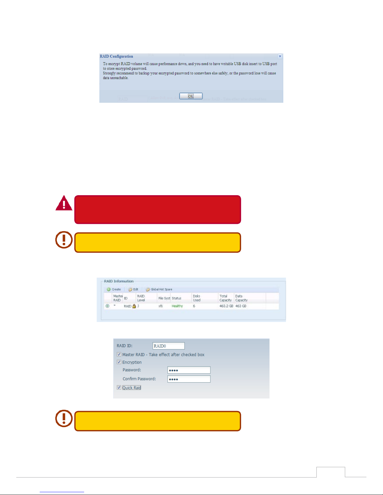
Selected whether the RAID volume will be encrypted or not. 5.
The RAID volume can protect data by using RAID Volume Encryption function to prevent
the risk of data exposure. To activate this function, the Encryption option needs to be en-data exposure. To activate this function, the Encryption option needs to be en-activate this function, the Encryption option needs to be en- this function, the Encryption option needs to be en-the Encryption option needs to be en- Encryption option needs to be en-needs to be enabled while the RAID is created and followed by a password input for identification. Also,
an external writable USB disk plugged into any USB port on the system is required to save
the password you have entered while the RAID volume is being created. See the screenshot
below for details.
Page 35
29
Chapter 3: System Administration
Once the Create button has been pressed with the Encryption checkbox enabled, the following
message pop-up will appear for confirmation.
After the RAID volume has been created, you may remove the USB disk until the next time the
system boots. The RAID volume cannot be mounted if the USB disk with the encryption key isn’t
found in any system USB port when the volume is accessed. To activate the encrypted volume, plug
the USB disk containing the encryption key and into any system USB port.
We strongly recommended copying the RAID volume encryption key to a safe place. You can find
the encryption key file from the USB disk in the following format:
(RAID volume created date)_xxxxxx.key
Please keep your USB disk in a safe place and also backup the encrypted
key.
There is no way to rescue data back if the key is lost.
With RAID volume encryption enabled, the system performance will go
down.
RAID volumes with encryption enabled will be displayed with a key lock symbol next to volume ID
name.
Quick RAID — Enabled the quick RAID setting is going to enhance RAID creation time. 6.
We recommend using the “Quick RAID” setting only if the hard disks are
brand new or if no existing partitions are contained.
Specify a stripe size — 64K is the default setting.7.
Page 36

30
Chapter 3: System Administration
Selected the file system you would like to have for this RAID volume. .8.
Press Submit to build the RAID storage volume.9.
Press “Yes” for RAID volume creation preparation. Then click “Finish” to start up with RAID 10.
volume building.
Page 37

31
Chapter 3: System Administration
Building a RAID volume may be time consuming, depending on the size
of hard drives and RAID mode. In general, if the RAID volume building
process is up to “RAID Building”, then the data volume is accessible.
Creating RAID destroys all data in the current RAID volume. The data will
be unrecoverable.
RAID Level•
You can set the storage volume as JBOD, RAID 0, RAID 1, RAID 5, RAID 6, or RAID 10 (depending on
model).
Level
Model
JBOD RAID 0 RAID 1 RAID 5 RAID 6 RAID 10
N2520/N2560
N4520/N4560
RAID configuration is usually required only when you first set up the device. A brief description of
each RAID setting follows:
RAID Levels
Level Description
JBOD The storage volume is a single HDD with no RAID support. JBOD requires a minimum of 1 disk.
RAID 0 Provides data striping but no redundancy. Improves performance but not data safety. RAID 0 requires a minimum of
2 disks.
RAID 1 Offers disk mirroring. Provides twice the read rate of a single disk, but same write rate. RAID 1 requires a minimum of
2 disks.
RAID 5 Data striping and stripe error correction information provided. RAID 5 requires a minimum of 3 disks. RAID 5 can sus-
tain one failed disk.
RAID 6 Two independent parity computations must be used in order to provide protection against double disk failure. Two
different algorithms are employed to achieve this purpose. RAID 6 requires a minimum of 4 disks. RAID 6 can sustain
two failed disks.
RAID 10 RAID 10 has high reliability and high performance. RAID 10 is implemented as a striped array whose segments are
RAID 1 arrays. It has the fault tolerance of RAID 1 and the performance of RAID 0. RAID 10 requires 4 disks. RAID 10
can sustain two failed disks.
Page 38

32
Chapter 3: System Administration
Creating RAID destroys all data in the current RAID volume. The data will
be unrecoverable.
Edit RAID•
On the RAID Information screen, press the Edit button to go to the RAID Information screen.
Using Edit RAID, you can select RAID ID and the Spare Disk.
Page 39

33
Chapter 3: System Administration
Remove RAID •
Click to remove the RAID volume. All user data and iSCSI created in the selected RAID volume will be
deleted.
To remove a RAID volume, follow the steps below:
On the RAID List screen, select the RAID volume by clicking on its radio button, and click RAID 1.
Information to open the RAID Configuration screen.
On the RAID Configuration screen, click Remove RAID.2.
A confirmation screen will appear, you will have to click “Yes” to complete t he “ Remove RAID” 3.
operation.
Remove RAID destroys all data in the selected RAID volume. The data
will be unrecoverable.
Expanding a RAID(Dose not apply to the N2520/N2560)•
To expand a RAID 1, RAID 5, or RAID 6 volume, follow the steps below:
Replace one of the hard drives in the RAID volume and allow it to automatically rebuild.1.
Once rebuilt, you can continue to replace any remaining disks in the RAID array. 2.
When you are done replacing hard drives, log on to Web Management. Navigate to Storage> 3.
RAID to open the RAID Configuration screen.
On the RAID Information screen, click Edit to open the RAID Configuration screen.4.
On the RAID Configuration screen, click Expand.5.
Page 40

34
Chapter 3: System Administration
Migrating a RAID(Dose not apply to the N2520/N2560)•
Once a RAID volume has been created, you may want to move it to other physical drives or change
the RAID array all together. To migrate a RAID 1, RAID 5 or RAID 6 volume, follow the steps below:
From the RAID Configuration screen, click Migrate RAID.1.
A list of possible RAID migration configurations will be listed. Select the desired migration 2.
scheme and click Apply.
The system will begin migrating the RAID volume.3.
Page 41

35
Chapter 3: System Administration
Migrating a RAID volume could take several hours to complete.•
The RAID migration feature is available only when it is congurable. •
Here is a list of limitation with RAID level migration function:
During RAID level migration, it is not permitted to reboot or shutdown system. 1.
For RAID migration from R1 to R5 or R1 to R6, all services will restart and “iSCSI” volume will be 2.
in read only mode but read/write of the “user data” will be possible during the operation.
The migration scheme below is based on Thecus IP Storage product’s
maximum possible combination. For other model which supports less
HDD, please refer to the web UI while RAID migration operates.
Below is a table listing of possible RAID migration schemes:
To
From RAID 0 RAID 5 RAID 6
RAID 1 [RAID 1] HDDx2 to [RAID 5] HDDx3
[RAID 1] HDDx2 to [RAID 5] HDDx4
[RAID 1] HDDx3 to [RAID 5] HDDx4
[RAID 1] HDDx2 to [RAID 6] HDDx4
[RAID 1] HDDx3 to [RAID 6] HDDx4
RAID 5 X [RAID 5] HDDx3 to [RAID 5] HDDx4 [RAID 5] HDDx3 to [RAID 6] HDDx4
Page 42

36
Chapter 3: System Administration
NAS Stacking (N4520/N4560 Only)3.4.3
The Thecus IP storage’s capacity can be expanded even further using the stackable function. With it,
users can expand the capacity of their network storage systems up to 5 other stack target volumes
which are located in different systems. These can be stacked through single network access like SMB
or AFP acting as a share folder type.
From the main menu, the stackable feature is located under “Storage”. Please refer the figure below
for reference.
A. Add a Stack Target Volume
From the figure above, click Add to access the stackable target device configuration page. Please
refer to the figure below:
With the added stack target you can “Enable” or “Disable” the stack target now or later depending on
usage required.
Page 43

37
Chapter 3: System Administration
Next, input the target IP address of the stackable device and click the Discovery button. The system
will list available target volumes from the inputted IP address.
Once the volume IP has been set, you may need to input a valid user name and password to validate
your access rights. If there is no user name and password needed to access target volume, then leave
it blank.
The Stacked Target name will become the network share name and will be displayed through
network access such as SMB. You may refer to the figure below to see the result. Please note the
naming limitation.
Page 44

38
Chapter 3: System Administration
From the figure above, the Stacked Target name is “pmmeeting”. The figures below show the result
before and after via Microsoft Network Access when settings have been completed.
The Browseable setting is the same method used for setting a system share folder. It designates
whether or not this folder will be visible through web disk. You may refer to the figure below for
reference when Yes and No are selected.
Page 45

39
Chapter 3: System Administration
The Public setting will be set the same way as the setting for the system share folder associated with
the ACL permission is. If Public is set to Yes, all users will be able to access it, and ACL button will be
grayed out. If Public is set to No, the ACL button will be available in the Stack Target List window.
Click Apply to save your changes.
B. Activate a Stack Target
After your settings have been applied, the system will bring you back to the Stack Target List window
as shown below. There is one stack target device that has been attached into this stack master.
Page 46

40
Chapter 3: System Administration
With this newly attached stack target device, you will see the information displayed and also have
access to several options to choose from.
In general, if the attached stack target device has been used by another Thecus NAS as stack target
volume, then the Format item will be display and system will recognize it straight away and display
its capacity. Otherwise, the Format item will be available and the Capacity and Status items will show
as “N/A” and “Unknown file system” respectively.
Next, click Format to proceed with formatting.
After the format is completed, the stack target volume will be created successfully. You will see the
volume’s capacity and status in the Stack Target List screen.
C. Edit a Stack Target
To make any changes to a stack target, click Edit for the corresponding stack target, and the system
will bring up the following dialogue window:
After your changes have been made, click Apply to confi rm any modifi cations. Once changes are ap- your changes have been made, click Apply to confi rm any modifi cations. Once changes are ap- changes have been made, click Apply to confi rm any modifi cations. Once changes are ap-s have been made, click Apply to confi rm any modifi cations. Once changes are ap- have been made, click Apply to confi rm any modifi cations. Once changes are ap-have been made, click Apply to confi rm any modifi cations. Once changes are ap- been made, click Apply to confi rm any modifi cations. Once changes are ap-, click Apply to confi rm any modifi cations. Once changes are ap- click Apply to confi rm any modifi cations. Once changes are ap-click Apply to confi rm any modifi cations. Once changes are ap-Apply to confirm any modifications. Once changes are ap-s. Once changes are ap-. Once changes are ap-Once changes are ap-hanges are ap-s are ap- are ap-are applied, the associated information will be updated on the Stack Target List window.
Page 47

41
Chapter 3: System Administration
D. Stack Target ACL
If the stack target Public setting set to Yes, then the ACL button will be grayed out. However, if Public
setting is set to No, then the ACL button will be available for you to setup user access permissions for
the stack target.
The ACL settings will be exactly the same as the system folder that you may have setup previously.
E. Reconnect a Stack Target
This is used to enable stack target devices that may have been disconnected due to a power outage
or a disconnected network. When this happens, the Reconnect button will become available. To at-a disconnected network. When this happens, the Reconnect button will become available. To at-. When this happens, the Reconnect button will become available. To at- When this happens, the Reconnect button will become available. To at-, the Reconnect button will become available. To at-button will become available. To at-will become available. To at-become available. To at-available. To at-To attempt to reconnect the stack target, click Reconnect.
Page 48

42
Chapter 3: System Administration
ISO Mount (N4520/N4560 Only)3.4.4
The ISO Mount feature is a very useful tool from the Thecus products. With it, users can mount an ISO
file and have the export name display all the details from the mounted ISO file.
From the main menu, the ISO Mount feature is located under “Storage”. Please refer the figure below
for reference.
Select the ISO Image Mounting function and the ISO Image Mounting window will appear as shown
here.
A. Add an ISO le
From the figure above, select an ISO file from the drop down share list.
After selection, the system will bring up the Mount table screen for further settings.
Page 49

43
Chapter 3: System Administration
To mount the new ISO file, select one file from the list of files and input the desired mounting name
into the “Mount as:” field. Click “ADD” t o confirm the completion of the mounting. If nothing is input
in the “Mount as” ISO file export name field, the system will automatically give an export name to the
ISO file. The mounting name will then be defined by the ISO file name.
After completion, the page will display all mounted ISO files.
You can click “Unmount” to eliminate a mounted ISO file.
B. Using ISO
The mounted ISO file will be located in the share folder of the same name as the file. Please refer the
screen shot below. Here, the ISO file “Thecus 01” wasn’t assigned a mounting name, so the system
automatically created a folder “Thecus 01”.
Page 50

44
Chapter 3: System Administration
iSCSI (N4520/N4560 Only)3.4.5
You may specify the space allocated for iSCSI. See the table below to the allowed iSCSI target num- See the table below to the allowed iSCSI target num-See the table below to the allowed iSCSI target num- iSCSI target num-number per system:
Model N4520/N4560
Allowed iSCSI volume 15
iSCSI Target•
To add iSCSI target volume, click iSCSI with associated RAID volume from its drop down list and
select the desired RAID volume.
iSCSI Tar get
Item Description
Add Click to allocate space to iSCSI target from associated RAID volume.
Modify Click this to modify the iSCSI Tar get .
Advanced
There are 3 options (iSCSI CRC/Checksum, Max Connections, Error Recovery Level) These currently
allow the Admin to Enable/Disable the Thecus IP storage associated with the iSCSI setting.
Delete Click this to delete the iSCSI Target.
Allocating Space for iSCSI Volume
Page 51

45
Chapter 3: System Administration
To allocate space for an iSCSI target on the current RAID volume, follow the steps below:
Under the iSCSI Target List, select iSCSI Target then click Add.1.
The Create iSCSI Volume screen appears.
Create iSCSI Volume
Item
Description
iSCSI Target Volume Enable or Disable the iSCSI Target Volume.
Target Name Name of the iSCSI Target. This name will be used by the Stackable NAS function to identify this ex-
port share.
iqn_Yea r Select the current year from the dropdown.
Iqn_Month Select the current month from the dropdown.
Authentication You may choose CHAP authentication or choose None.
Username Enter a username.
Password Enter a password.
Password Confirm Reenter the chosen password
Mutual CHAP With this level of security, the target and the initiator authenticate each other.
Page 52

46
Chapter 3: System Administration
Username Enter a username.
Password Enter a password.
Password Confirm Reenter the chosen password
RAID ID ID of current RAID volume.
LUN Allocation
Two modes can be choose from:
Thin-provision: iSCSI thin-provisioning shares the available physical capacity to multiple
iSCSI target volumes. It allows virtual capacity to be assigned to targets prior to adding
physical space when it has run out.
Instant Allocation: Allocate available physical capacity to iSCSI target volumes.
LUN Name Name of the LUN.
Unused Unused space on current RAID volume.
Allocation Percentage and amount of space allocated to iSCSI volume.
LUN ID Specific Logic unit ID number.
iSCSI Block size The iSCSI block size can be set under system advance option, default is 512 Bytes.
[ 4K ] block size while more than 2TB capacity will be configured in Windows XP.
[ 512 Bytes ] block size for application like VMware etc.
Be sure the iSCSI target volume has been enabled or it will not list out
while using Initiator to get associated iSCSI target volumes.
The iSCSI target volume creation will associate at least one LUN together.
It can be assigned either “Thin-Provisioning” or “Instant Allocation”.
Enable the iSCSI Target Volume by selecting Enable.2.
Enter a Target Name. This will be used by the Stackable NAS function to identify this export 3.
share.
Choose the current year from the Year dropdown.4.
Choose the current month from the Month dropdown.5.
Choose to enable CHAP authentication or choose None.6.
If you’ve enabled CHAP authentication, enter a username and a password. Confirm your cho-7.
sen password be reentering it in the Password Confirm box.
Choose Thin-Provision or Instant Allocation8.
Enter a LUN Name.9.
Designate the percentage to be allocated from the Allocation drag bar.10.
When iSCSI target volume has been created, the LUN ID is configurable from 0 to 254 with a 11.
default of the next available number in ascending numerical order. The LUN ID is unique and
cannot be duplicated.
Choose [ 4K ] block size to have iSCSI target volume over 2TB barrier or [ 512 Bytes ] block size 12.
in some application needed.
Click OK to create the iSCSI volume.13.
Modify iSCSI Volume•
To modify iSCSI target on the current RAID volume, follow the steps below:
Under the iSCSI Target List, click Modify.1.
The Modify iSCSI Volume screen appears.
Page 53

47
Chapter 3: System Administration
Modify your settings. Press ok to change.2.
Expand Volume•
The iSCSI volume is now able to expand its capacity from unused space (Instant Allocation mode
only). From the volume list, simply select the iSCSI volume you like to expand and click the Expand
button:
Page 54

48
Chapter 3: System Administration
You will then see the dialog box displayed below. Drag the Expand Capacity bar to the size you want.
Then press Expand to confirm the operation.
Delete Volume•
To delete volume on the current RAID volume, follow the steps below:
Under the Volume Allocation List, click Delete.1.
The Space Allocation screen appears.
Page 55

49
Chapter 3: System Administration
Press YES. All data in the volume will be removed.2.
iSCSI Thin-Provisioning•
If iSCSI Thin-Provisioning is selected when creating an iSCSI target volume, virtual memory is as- iSCSI target volume, virtual memory is as- virtual memory is assigned to the target, allowing the physical memory to reach maximum capacity and adding new
disks only when needed.
To setup iSCSI thin-provisioning, simply select “Thin-Provision” mode from the “Create LUN” setting
screen.
Next, allocate capacity for the iSCSI thin-provision volume by dragging the Allocation bar to the de-the iSCSI thin-provision volume by dragging the Allocation bar to the de-iSCSI thin-provision volume by dragging the Allocation bar to the de-ging the Allocation bar to the de- the Allocation bar to the de-Allocation bar to the de-bar to the de-the desired size.
After the size has been determined, click OK to confirm. Now you will see the iSCSI thin-provisioning
volume is available from the list. Please refer to the screenshot below.
If creating an iSCSI target volume under “Instant Allocation”, physical memory is assign to the target,
being limited by the available memory. For the iSCSI target volume created under “thin-provisioni n g ”,
virtual memory is assigned to the volume, which can go up to 16384GB (16TB).
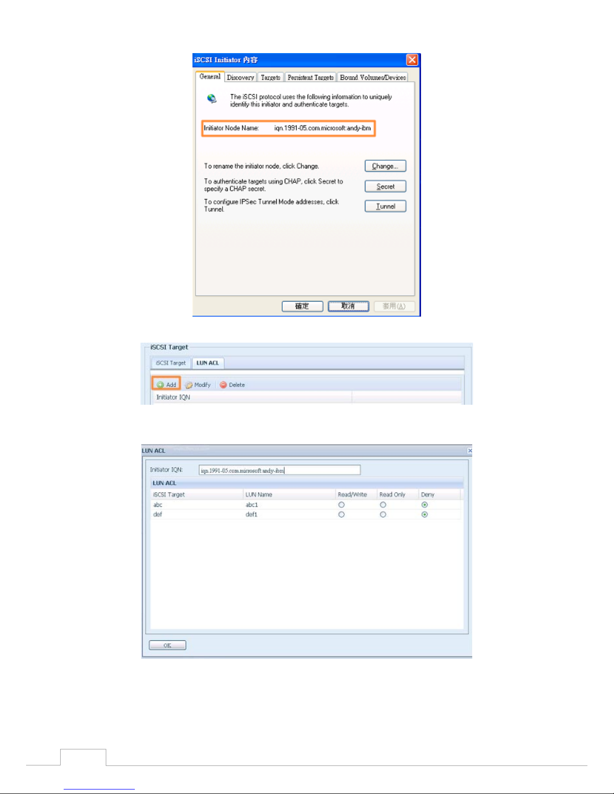
LUN ACL•
After iSCSI target has been created, you are one step away from using the iSCSI volume. Under “LUN
ACL”, you need to add “Initiator iqn” and setup ACL access privileges to determine the accessibility.
Please refer the screen shot below for where “Initiator iqn” can be found.
Page 56
50
Chapter 3: System Administration
From the LUN ACL setting screen click “Add”:
Next, input “Initiator iqn” and setup iSCSI target volume access privileges from the available list. Apply
by clicking the OK button.
The accessible Initiator will be listed as shown in the screen shot displayed below.
Page 57

51
Chapter 3: System Administration
The listed “Initiator iqn” can be modified or deleted by selecting the desired iqn and pressing Modify
or Delete.
Advance Option•
There are 3 available options for the user to operate Thecus IP storage associated with iSCSI setting.
The details are listed in the following screenshot. If the options are modified, the system will need to
reboot for the changes to take place.
iSCSI CRC/Checksum
To enable this option, the initiator can connect with “Data digest” and “Header digest”.
Max Connections
The maximum number of iSCSI connections.
Page 58

52
Chapter 3: System Administration
Error Recovery Level
The Error Recovery Level (ERL) is negotiated during a leading iSCSI connection login in traditional
iSCSI (RFC 3720) and iSER (RFC 5046).
ERL=0: Session Recovery
ERL=0 (Session Recovery) is triggered when failures within a command, within a connection, and/or within TCP occur. This causes all of the previous connections from the failed
session to be restarted on a new session by sending a iSCSI Login Request with a zero
TSIHRestart all iSCSI connections on any failure.
ERL=1: Digest Failure Recovery
ERL=1, only applies to traditional iSCSI. For iSCSI/SCTP (which has its own CRC32C)
and both types of iSER (so far), handling header and data checksum recovery can be
disabled.
ERL=2: Connection Recovery
ERL=2, allows for both single and multiple communication path sessions within a iSCSI
Nexus (and hence the SCSI Nexus) to actively perform realligence/retry on iSCSI ITTs
from failed iSCSI connections. ERL=2 allows iSCSI fabrics to take advantage of recovery
in all regards of transport level fabric failures, and in a completely OS independent
fashion (i.e. below the host OS storage stack).
File Sharing/Privilege3.5
The Thecus IP storage has built-in user database that allows administrators to manage user access
using different group policies. From the File Sharing/Privilege menu, you can create, modify, and de-File Sharing/Privilege menu, you can create, modify, and de- menu, you can create, modify, and delete users, and assign them to groups that you designate.
ADS Support (N4520/N4560 Only)3.5.1
If you have a Windows Active Directory Server (ADS) to handle the domain security in your network,
you can simply enable the ADS support feature; the Thecus IP storage will connect with the ADS
server and get all the information of the domain users and groups automatically. From the Accounts
menu, choose Authentication item and the ADS Support screen appears. You can change any of
these items and press Apply to confirm your settings.
A description of each item follows:
ADS/NT Support
Page 59

53
Chapter 3: System Administration
Item Description
Work Group / Domain Name Specifies the SMB/CIFS Work Group / ADS Domain Name (e.g. MYGROUP).
ADS Support Select Disable to disable authentication through Windows Active Directory Server.
ADS Server Name Specifies the ADS server name (e.g. adservername).
ADS Realm Specifies the ADS realm (e.g. example.com).
Administrator ID Enter the administrators ID of Windows Active Directory, which is required for Thecus IP storage to
join domain.
Administrator Password Enter the ADS Administrator password.
Apply To save your settings.
To join an AD domain, you can refer to the figure here and use the example below to configure the
Thecus IP storage for associated filed input:
AD Domain Example
Item Information
Work Group / Domain
Name
domain
ADS Support Enable
ADS Server Name Computer1
ADS Realm Domain.local
Administrator ID Administrator
Administrator Password ***********
The DNS server specified in the WAN/LAN1 configuration page •
should be able to correctly resolve the ADS server name.
The time zone setting between Thecus IP storage and ADS should •
be identical.
The system time difference between Thecus IP storage and ADS •
should be less than ve minutes.
The Administrator Password eld is for the password of ADS (Active •
Directory Server) not Thecus IP storage.
Local User Conguration3.5.2
From the File Sharing/Privilege menu, choose the User item, and the Local User Configuration screen
appears. This screen allows you to Add, Edit, and Remove local users.
Page 60

54
Chapter 3: System Administration
Local User Conguration
Item Description
Add Press the Add button to add a user to the list of local users.
Edit Press the Edit button to modify a local user.
Remove Press the Remove button to delete a selected user from the system.
Add Users•
Click on the Add button on Local User Configuration screen, and Local User Setting screen 1.
appears.
On the Local User Setting screen, enter a name in the User Name box.2.
Enter a User ID number or leave blank to use the system default value. 3.
Enter a password in the Password box and re-enter the password in the Confirm box.4.
Select which group the user will belong to. Group Members is a list of groups this user be-5.
longs to. Group List is a list of groups this user does not belong to. Use the << or >> buttons
to have this user join or leave a group.
Press the Apply button and the user is created.6.
All users are automatically assigned to the ‘users’ group.•
Page 61

55
Chapter 3: System Administration
Edit Users•
Select an existing user from the Local User Configuration screen.1.
Click on the Edit button, and the Local User Setting screen appears.2.
From here, you can enter a new password and re-enter to confirm, or use the << or >> but-3.
tons to have this user join or leave a group. Click the Apply button to save your changes.
Remove Users•
Select an existing user from the Local User Configuration screen.1.
Click on Remove button and the user is deleted from the system.2.
Local Group Conguration3.5.3
From the File Sharing/Privilege menu, choose the Group item, and the Local Group Configuration
screen appears. This screen allows you to Add, Edit, and Remove local groups.
Page 62

56
Chapter 3: System Administration
Local Group Conguration
Item Description
Add Press the Add button to add a user to the list of local groups.
Edit Press the Edit button to modify a selected group from the system.
Remove Press the Remove button to delete a selected group from the system.
Add Groups•
On the Local Group Configuration screen, click on the Add button. 1.
The Local Group Setting screen appears.2.
Enter a Group Name.3.
Enter a Group ID number. If left blank, the system will automatically assign one.4.
Select users to be in this group from the Users List by adding them to the Members List using 5.
the << button.
Click the Apply button to save your changes. 6.
Edit Groups•
On the Local Group Configuration screen, select a group name from the list.1.
Press the Edit button to modify the members in a group.2.
To add a user into a group, select the user from the Users List, and press the << button to 3.
move the user into the Members List.
To remove a user from a group, select the user from Members List, and press the >> button.4.
Click the Apply button to save your changes.5.
Page 63

57
Chapter 3: System Administration
Remove Groups•
On the Local Group Configuration screen, select a group name from the list.1.
Press Remove to delete the group from the system.2.
Batch Users and Groups Creation3.5.4
The Thecus IP storage can also add users and groups in batch mode. This enables you to convenient-Thecus IP storage can also add users and groups in batch mode. This enables you to convenient- can also add users and groups in batch mode. This enables you to conveniently add numerous users and groups automatically by importing a simple comma-separated plain text
(*.txt) file.
From the File Sharing/Privilege menu, click Batch Input and the Batch User and Group Creation dia-File Sharing/Privilege menu, click Batch Input and the Batch User and Group Creation dia-menu, click Batch Input and the Batch User and Group Creation dialogue will appear. To import your list of users and groups, follow these steps:
Click the Browse icon to locate your comma-separated text file. 1.
The information in the text file should follow this format:
[USERNAME], [PASSWORD], [GROUP]
Click Open.2.
Click Import to begin the user list import.3.
Page 64

58
Chapter 3: System Administration
Share Folder3.5.5
From the File Sharing/Privilege menu, choose Share Folders, and the Shared Folder screen appears.
This screen allows you to create and configure folders on the Thecus IP storage volume.
Adding Folders•
On the Folder screen, press the Add button and the Add Folder screen appears. This screen allows
you to add a folder. After entering the information, press Apply to create new folder.
Add Folder
Item Description
RAID ID RAID volume where the new folder will reside.
Folder Name Enter the name of the folder.
Public Admit or deny public access to this folder.
Apply Press Apply to create the folder.
Modify Folders•
On the Folder screen, press the Edit button and the Modify Folder screen appears. This screen allows
Page 65

59
Chapter 3: System Administration
you to change folder information. After entering the information, press Apply to save your changes.
Modify Folder
Item Description
Folder Name Enter the name of the folder.
Public Admit or deny public access to this folder.
Apply Press Apply to create the folder.
Remove Folders•
To remove a folder, press the Remove button from the specified folder row. The system will confirm
folder deletion. Press Yes to delete the folder permanently or No to go back to the folder list.
All the data stored in the folder will be deleted once the folder is deleted.
The data will not be recoverable.
Page 66

60
Chapter 3: System Administration
NFS Share (N4520/N4560 Only)•
To allow NFS access to the share folder, enable the NFS Service, and then set up hosts with access
rights by clicking Add.
NFS Share
Item Description
Hostname Enter the name or IP address of the host
Privilege Host has either read only or writeable access to the folder.
OS Support There are two selections available:
Unix / Linux System•
AIX (Allow source port > 1024)•
Choose the one which best fits your needs.
ID Mapping There are three selections available:
Guest system root account will have full access to this share (root:root).•
Guest system root account will be mapped to anonymous user (nobody:nogroup) on NAS.•
All user on guest system will be mapped to anonymous user (nobody:nogroup) on NAS.•
Choose the one which best fits your needs.
Sync / Async Choose to determine the data “Sync” at once or “Async” in arranged batch.
Apply Click to save your changes.
Page 67

61
Chapter 3: System Administration
Samba Conguration•
On the Folder screen, press the Samba button and the Samba Configuration screen appears. This
screen allows you to setup samba configuration for associated folder. After entering the information,
press Apply to activate input settings.
Samba Conguration
Item Description
RAID ID RAID volume where the new folder will reside.
Folder Name Enter the name of the folder.
Public Admit or deny public access to this folder.
Apply Press Apply to create the folder.
Folder and sub-folders Access Control List (ACL)•
On the Folder screen, press the ACL button, and the ACL setting screen appears. This screen allows
you to configure access to the specific folder and sub-folders for users and groups. Select a user or
a group from the left hand column and then choose Deny, Read Only, or Writable to configure their
access level. Press the Apply button to confirm your settings.
Page 68

62
Chapter 3: System Administration
ACL setting
Item Description
Deny Denies access to users or groups who are displayed in this column.
Read Only Provides Read Only access to users or groups who are displayed in this column.
Writable Provides Write access to users or groups who are displayed in this column.
Recursive Enable to inherit the access right for all its sub-folders.
To configure folder access, follow the steps below:
On the ACL screen, all network groups and users are listed in the left hand column. Select a 1.
group or user from this list.
With the group or user selected, press one of the buttons from the three access level col-2.
umns at the top. The group or user then appears in that column and has that level of access
to the folder.
Continue selecting groups and users and assigning them access levels using the column but-3.
tons.
To remove a group or user from an access level column, press the Remove button in that 4.
column.
When you are finished, press Apply to confirm your ACL settings5.
If one user has belonged to more than one group with different
privilege, then the priority of the privilege will be as followed:
Deny > Read Only > Writable
To setup sub-folders ACL, click on “ ” symbol to extract sub folders list as screen shot shows below.
You may carry on with same steps as share level ACL setting.
Page 69

63
Chapter 3: System Administration
The ACL can only be set for share and sub-folders level, not for les.
The ACL screen also allows you to search for a particular user. To do this, follow the steps below:
In the blank, enter the name of the user you would like to find. 1.
From the drop down select the group you would like to search for the user in.2.
Click Search.3.
User Quota3.5.6
The Thecus IP storage support local or AD users with storage quota limitations in each RAID volume
of the system. To enable this function, simply click “Enable”, then apply.
Next, each user can be setup a global storage quota size for each RAID volume. Simply click on “Quota
Size” for each user and input the desired capacity. After the setup is complete, please click on “Apply”
to activate the user quota size.
Page 70

64
Chapter 3: System Administration
User and Group Backup3.5.7
The user and group backup feature allow system users and groups to be backed up to another
location and be restored if needed.
Please note, when restoring previous backup users and groups, the current users and groups list will
be replaced from this restore file’s contents.
LDAP Support (N4520/N4560 Only)3.5.8
The LDAP is the other way to authenticate login users who has joined LDAP server, fill in the LDAP
server information and get LDAP authentication started. Please make sure that the LDAP server has a
Samba sam and a POSIX ObjectClass account.
Page 71

65
Chapter 3: System Administration
A description of each item follows:
LDAP Support
Item Description
LDAP Service Enable or Disable LDAP service.
LDAP Server IP Input LDAP server IP address.
Base Domain Input base domain information ex. dc=tuned, dc=com, dc=tw
Manager Input manager’s name.
Password Input manager’s password
Apply Click Apply to save your changes.
Check ObjectClass Click this checkbox to ensure LDAP server has a Samba sam and a POSIX account or it may not work properly
for LDAP client authentication.
Page 72

66
Chapter 3: System Administration
Network Service3.6
Use the Network Service menu to make network service support settings.
Samba / CIFS3.6.1
There are options allow Admin to Enable/Disable to operate Thecus IP storage associated with
Samba / CIFS protocol. With the option changed, it will need to reboot system to activate.
Samba Service •
Used for letting the operating system of UNIX series and SMB/CIFS of Microsoft Windows operating
system (Server Message Block / Common Internet File System).Do the link in network protocol.
Enable or Disable SMB/CIFS protocol for Windows, Apple, Unix drive mapping
.
In some environments, due to security concerns, you may wish to disable
SMB/CIFS as a precaution against computer viruses.
Samba Anonymous Login Authentication•
To enable this option, no matter there is share folder has been created in public access. The user
account and password is needed from system to access under SMB/CIFS protocol. On the other
hand, no more anonymous login is allowed.
Samba is Native mode•
The Thecus IP storage is supported Samba mode options. In the ADS environment with “Native”
mode selected then Thecus IP storage is capable to become local master position.
UNIX Extension•
The default is enable for Samba usage, with situation using Mac OSX with smb connection may have
permission issue. When it happened, please setup “UNIX Extension” disable to get issue solved.
Samba Recycle Bin•
The Thecus IP storage is supported recycle bin via SMB/CIFS protocol.
Page 73

67
Chapter 3: System Administration
Simply enable the “Recycle Bin” function and “Recycle Folder Display” then all of deleted files/folders
will reside in the “_NAS_Recycle_(Associated RDID Volume)” share folder.
For example, the system has created 2 RAID volumes with ID “RAIDpm” and ‘RAID”. Then it will have 2
recycle bin folder appear as “_NAS_Recycle_RAID” and “_NAS_Recycle_RAIDpm”.
There are 2 more setting could help to manage the recycle bin for deleted folders/files.
Setup the “Day” to remove deleted folders/files which has resided in recycle bin permanently. 1.
Left default value “0” if desired to clean up recycle bin manually.
Setup the “Size” for recycle bin to allow deleted folders/files can store. Left default value “0” 2.
with no limitation.
The deleted les/folders which have resided in recycle bin will keep •
its permission. On the other hand, only the admin and owner can
view/read/write these folders/les.
If deleted single le size is large than 2GB then it won’t reside in the •
recycle bin but erase permanently.
Page 74

68
Chapter 3: System Administration
AFP (Apple Network Setup)3.6.2
From the System Network menu, choose the AFP item, and the AFP Support screen appears. This
screen displays the configuration items for the Apple Filing Protocol. You can change any of these
items and press Apply to confirm your settings.
A description of each item follows:
Apple Network Conguration
Item Description
AFP Server Enable or disable Apple File Service to use the Thecus IP storage with MAC OS-
based systems.
MAC CHARSET Specifies the code page from the drop down list.
Zone Specifies Zone for Applet Talk service.
If your AppleTalk network uses extended networks and is assigned with multiple
zones, assign a zone name to the Thecus IP storage. If you do not want to assign a
network zone, enter an asterisk (*) to use the default setting.
Time Machine Click the enable checked box if you would like your MAC system to use the Thecus
IP storage as MAC time machine backup.
Time Machine backup folder Select from the drop down list to designate the folder for time machine backup
destination.
Page 75

69
Chapter 3: System Administration
NFS Setup (N4520/N4560 Only)3.6.3
From the System Network menu, choose the NFS item, and the NFS Support screen appears. The
Thecus IP storage can act as an NFS server, enabling users to download and upload files with their
favorite NFS clients. Press Apply to confirm your settings.
A description of each item follows:
NFS Server Setting
Item Description
NFS Enable or Disable NFS support.
Apply Click Apply to save your changes.
FTP 3.6.4
The Thecus IP storage can act as an FTP server, enabling users to download and upload files with
their favorite FTP programs. From the System Network menu, choose the FTP item, and the FTP
screen appears. You can change any of these items and press Apply to confirm your settings.
A description of each item follows:
FTP
Item Description
FTP Enables FTP Service on the Thecus IP storage.
Security FTP Enable or disable Security FTP, be sure the client FTP software has also security FTP setting
enabled.
Port Specifies the port number of an incoming connection on a non-standard port.
External IP Input the public IP address of the router when the Thecus secure FTP server has been enabled.
This can help to respond to the ftp client with proper communication information.
Passive Port Range
(30000-32000)
Limited port range for the FTP server to use.
FTP ENCODE If your FTP client or operating system does not support Unicode (e.g. Windows® 95/98/ME or
MAC OS9/8), select the same encoding as your OS here in order to properly view the files and
directories on the server. Available options are BIG5, HZ, GB2312, GB18030, ISO, EUC-JP, SHIFT-JIS
and UTF-8.
Page 76

70
Chapter 3: System Administration
Allow Anonymous FTP Access Upload/Download: Allow anonymous FTP users to upload or download files to/from public
folders.
Download: Allow anonymous FTP users to download files from public folders.
No access: Block anonymous FTP user access.
Auto Rename If checked, the system will automatically rename files that are uploaded with a duplicate file
name. The renaming scheme is [filename].#, where # represents an integer.
Upload Bandwidth You may set the maximum bandwidth allocated for file uploads. Selections include Unlimited, 1
~ 32 MB/s.
Download Bandwidth You may set the maximum bandwidth allocated for file downloads. Selections include Unlim-
ited, 1 ~ 32 MB/s.
To access the share folder on the Thecus IP storage, use the appropriate user login and password
set up on the Users page. Access control to each share folder is set up on the ACL page (Storage
Management > Share Folder > ACL).
TFTP (N4520/N4560 Only)3.6.5
Thecus IP storage can act as a TFTP server, enabling users to download and upload files with their
favorite TFTP programs. From the System Network menu, choose the TFTP item, and the TFTP screen
appears. You can change any of these items and press Apply to confirm your settings.
A description of each item follows:
TFTP
Item Description
TFTP Enables TFTP Service on the Thecus IP storage.
IP Checked WAN/LAN1 or LAN2 to enable port use
Port Specifies the port number of an incoming connection on a non-standard port.
Share Folder Select the file stored folder, it cannot be empty.
Folder Permission Select the folder permission
WebService 3.6.6
From the Network Service menu, choose the WebService item, and the WebService Support screen
appears. This screen displays the service support parameters of the system. You can change any of
these items and press Apply to confirm your settings.
Page 77

71
Chapter 3: System Administration
A description of each item follows:
Web Service
Item Description
HTTP (WebDisk) Support Enable or disable WebDisk support. Enter the port number if this option is enabled. The port
number is default 80.
HTTPs (Secure WebDisk) Support Enable or disable secure WebDisk support. Enter the port if this option is enabled.
Certificate Type Select “User” if there is available Certification ID ex. Apply from VeriSign. Or using system default
by select “System”.
Certificate File Upload Certificate File if choose Certificate type “User”.
Certificate Key File Upload Certificate Key File if choose Certificate type “User”.
CA Certificate File Upload CA Certificate File if choose Certificate type “User”.
Restore All SSL Certificate Files Click to set back to default certification details.
Apply Click “Apply” to confirm the changes.
Disable HTTP support and Enable Secure HTTP support to guarantee
secure access.
UPnP3.6.7
This device supports UPnP Media server, which allows users to play media files with UPnP client (ex.
DMA devices). Enable or disable Universal Plug and Play protocol. UPnP helps to find the IP address
of Thecus IP storage.
Bonjour Setting3.6.8
Bonjour, is Apple Inc.’s trade name for its implementation of Zeroconf, a service discovery protocol.
Bonjour locates devices such as printers, as well as other computers, and the services that those devices offer on a local network using multicast Domain Name System service records. This definitive
guide walks you through Bonjour zero-configuration networking with a complete description of the
protocols and technologies used to create Bonjour enabled applications and devices.
Page 78

72
Chapter 3: System Administration
SSH3.6.9
The device is now SSH protocol supported. It allows user to use SSH and have console to manipulate
as needed. The SSH default login user name is “root” with full privilege and password is admin’s pass- needed. The SSH default login user name is “root” with full privilege and password is admin’s pass-“root” with full privilege and password is admin’s pass-root” with full privilege and password is admin’s pass-” with full privilege and password is admin’s pass- with full privilege and password is admin’s pass-privilege and password is admin’s pass- and password is admin’s pass-password is admin’s pass- is admin’s pass-’s pass-s pass-password. The default admin password is “admin” so once the admin password has changed then SSH
login need to change the password too.
A description for each item as following:
SSH
Item Description
SSH Service Enable or disable SSH service.
Port The port number is default 22.
SFTP Enable or disable SFTP protocol under SSH service.
Apply Click “Apply” to confirm the changes.
DDNS3.6.10
To set up a server on the Internet and enable the users to connect to it easily, a fixed and easy-to
remember host name is often required. However, if the ISP provides only dynamic IP address, the IP
address of the server will change from time to time and is difficult to recall. You can enable the DDNS
service to solve the problem.
After enabling the DDNS service of the NAS, whenever the NAS restarts or the IP address is changed,
the NAS will notify the DDNS provider immediately to record the new IP address. When the user tries
to connect to the NAS by the host name, the DDNS will transfer the recorded IP address to the user.
The NAS supports the DDNS providers:
DyDNS.org(Dynamic DNS),DyDNS.org(Custom DNS),DyDNS.org(Static DNS),
www.zoneedit.com,www.no-ip.com.
Page 79

73
Chapter 3: System Administration
A description for each item as following:
DDNS
Item Description
DDNS Service Enable or disable DDNS service.
Register Choose the service provider from the drop down list.
User name Input user name with DDNS registry.
Password Input password with DDNS registry.
Domain name Input domain name with DDNS registry.
Apply Click “Apply” to confirm the changes.
UPnP Port Management3.6.11
One of the most convent way to allow users to access required services such as FTP, SSH, web disk
and http etc. from Internet environment is setting UPnP port management.
To set up this UPnP port forwarding feature, please be sure that the router has “UPnP Service”
Enabled. The following is an example from one of the router manufacture with UPnP Configuration
page.
After the router has enabled “UPnP Service” then you will have information come from associated
router to UPnP port management as shown in the screen shot below.
Page 80

74
Chapter 3: System Administration
And click “Add Rule” to add more port mapping from Internet to access desired services or press
“Refresh” to get most updated list.
A description for each item as following:
UPnP Port Management
Item Description
Start port Specific port number starts with.
End port Specific port number ended
Protocol Choose the protocol for port forwarding needed.
Description Specific the port services if applicable.
Apply Click “Apply” to confirm the changes.
Cancel Click “Cancel” to abort the changes
Some of the routers do not allow the input of port number below 1024.
So it may have resulted “setting fails”.
Page 81

75
Chapter 3: System Administration
Application Server3.7
The Thecus IP storage supports built-in application such as iTunes server as well as add-on official or
third -party applications.
iTunes® Server (Built in)3.7.1
With the built-in iTunes server capability, Thecus IP storage enables digital music to be shared and
played anywhere on the network!
From the Network menu, choose the iTunes item, and then the iTunes Configuration screen appears.
You may enable or disable the iTunes Service from here. Once enabled, enter the proper information
for each field and press Apply to save your changes.
See the following table for a detailed description of each field:
iTunes Conguration
Item Description
iTun es Service Enable or disable the iTunes Service.
iTun es Server Name Name used to identify Thecus IP storage to iTunes clients.
Password Enter a password to control access to your iTunes music.
Rescan Interval Rescan interval in seconds.
MP3 Tag Encode Specify tag encoding for MP3 files stored in Thecus IP storage. All ID3 tags will be sent out in UTF-8 for-Thecus IP storage. All ID3 tags will be sent out in UTF-8 for-. All ID3 tags will be sent out in UTF-8 for-
mat.
Once the iTunes service is enabled, Thecus IP storage will make all music located in the Music folder
available for iTunes-equipped computers on the network.
Add-on Ocial Applications3.7.2
There are several default pre-loaded official applications such as WebDisk, Piczza (Photo server) and
Transmission-Kit (BT download manager) that can be found from the Application Server category.
Module Installation3.7.3
From the Application Server Category, choose the Module Installation item and the Module
Management screen appears. Here is the entry for all of third party user module could install from.
Page 82

76
Chapter 3: System Administration
NAS Application3.7.4
Click on NAS Application from the Application Server category, it will list the current system software
and official application status.
Backup3.8
There are a number of ways to back up data with the Thecus IP storage.
Rsync Target Server3.8.1
When it comes to backing up your data, it’s very important to have flexibility. Data guard provides
you with many options, including full backup for all shares, custom backup for selected shares and
iSCSI volume backup. Being based on the Linux operating system, it is also much more stable and
experiences much less frequent data loss during transfer than other remote backup systems.
-For this tutorial you will need to use Rsync Target Server (Step 1) and Data Guard (Step 2+3) under
Backup for this client/server backup feature. It also can be named for function “Remote Replication”.
Step 1 – Enabling Rsync on your target (backup) NAS
-Log in to your target (backup) NAS through the UI in your web browser
-Go to Rsync Target Server under Backup in the menu of the UI
Page 83

77
Chapter 3: System Administration
Enable Rsync Target Server1.
Add a username and password (they can be different than your NAS’s username and 2.
password)
Select Apply3.
You will need this user name and password while the data is going to
remotely backup to this Rsync target server.
Now Rsync is turned on your NAS, which means it can be used as a target for Rsync backup, in other
words, only the backup NAS needs to be activated in this way.
Data Guard (Remote Backup)3.8.2
Step 2 – Setting up your backup task and schedule on your source NAS
-Log in to your other NAS (your source NAS) through the UI in your web browser
-Go to Data Guard under Backup in the System Management category of the UI
-From the Data Guard function list, choose Add
Remote Data backup
Item Description
Add Add new task.
Edit Edit select task.
Remove Remove select task
Start If associated task has been setup in schedule and like to start at once, click on to start task right
away.
Stop Stop the associated running task. The other scenario is if a task has been setup in real-time then
clicking “Stop” can terminate the running process. Simple click ‘Start” to re-start the real-time
operation.
Restore Restore the associated task
Log Click to view the associated task in process details.
Restore NAS Configuration Click to restore system configuration from selected destination to source unit. More details will
describe in sections.
The data backup setup wizard appears as below, click on ‘Remote Backup”:
Page 84

78
Chapter 3: System Administration
Then 3 different selections appear and can be chosen from:
Remote Data backup
Item Description
Full Backup The “Full backup” will have all shares from source backup to destination. It could also create shares
automatically from destination if it is not existent. This only applies if the target server is the same
model as the source.
Custom Backup The “Custom backup” allows user to choose desired shares backup to destination.
iSCSI Backup The “iSCSI backup” can backup iSCSI volume as single file to destination.
Page 85

79
Chapter 3: System Administration
Full Backup•
Click on full backup and the setup screen appear as below. Fill in the remote target IP (Destination)
and port (need to be changed only if this port is already in use).
If encryption is required then enable it. Please make sure the associated target server also has
encryption enabled.
Carry on with inputting valid remote target server account name and password.
After the settings are complete, please click on “Connection Test”. The source unit will try to connect
with the associated target system. If a connection can be built up successfully then “Connection
passed” will be prompted, otherwise “Failed” will appear.
Click “Next” and more setting will appear.
Page 86

80
Chapter 3: System Administration
-Fill out all the necessary details and choose your parameters
Add Rsync Backup Task
Item Description
Task Name This is how this task will appear in the task list.
Backup Type Real time:
It will backup folders/files from source to target on the fly. On the other hand, any
changes from the source will back up to the target right away.
Schedule:
The task will start only according to the schedule.
Sync Type Sync mode:
Makes your source match your target completely; deleting and adding files on your
target as they are deleted and added on your source.
Incremental Mode :
Makes your source match your target and keep all old files; adding files on your target
as they are added on your source, but NOT deleting files on your target as they are deleted on your source.
Compress With this option, compress the file data as it is sent to the destination machine, which
reduces the amount of data being transmitted – something that is useful over a slow
connection.
Backup NAS Config Enabling this will back up the source unit system configurations to the designed path
on the target system.
Resume Partial File
Handle Sparse File Try to handle sparse file efficiently so they take up less space on the destination.
Keep ACL Setting It will backup not just data itself but also ACL configuration with associated folders/
files.
Log Location
Choose the folder to save the log details while the task is executed.
Speed Limit
Input the bandwidth control for data backup operation.
Timeout Limit
Setup the timeout when trying to build up a connection in between the source and
the target system.
Enable Schedule
If backup is set as “Schedule”, please input the related period and time.
After the required fields are filled and the parameters are setup, click ‘Finish” to complete. The data
guard task will appear in the list as shown below.
Page 87

81
Chapter 3: System Administration
From the task list, you can now see the newly added task “fullback01”. The backup is setup as “real
time”. From the status field, “Processing” can be read as the back-up is performed on the fly.
Custom Backup•
The custom backup setting is similar to the full backup. The only differences are explained below:
Inputs the share folder name of target sever where the source is going to backup. The sub-1.
folder can be left as blank.
Select the source share folder(s) which are desired to be backed up to the target server. You 2.
can also click on “Select All” from top right corner check box.
Page 88

82
Chapter 3: System Administration
Click “Next” and more setting appears. These are the as the settings for “Full backup”3.
Click “Finish” and the data guard task will appear in the list as shown below.4.
From the task list, you can now see the newly added “customback01”. This backup is setup as
“schedule”.
Page 89

83
Chapter 3: System Administration
iSCSI Backup•
If the source unit contains iSCSI volume, it can be backed up to the target unit as a single file. The
procedure is the same as for the previous “Full backup” and “Custom backup”, select “iSCSI backup”
from data guard wizard.
Inputs the share folder name of the target sever where the source is going to backup. The 1.
sub-folder can be left as blank.
Select the iSCSI target volume which you wish to back up to the target server.2.
Click “Next” and more settings will appear. It is slightly differing from “Full backup” and “Custom 3.
backup”. Only “Schedule” backup is supported with less options.
Page 90

84
Chapter 3: System Administration
4. Click “Finish” and the data guard task will appear in the list as shown below.
From the task list, you can now see the newly added “iscsiback”. This backup is setup as “schedule”.
The source folder name will use iSCSI_+target volume name. So here it
is displayed as “iSCSI_pmtest”. pmtest is the iSCSI target name when the
iSCSI target was created.
The iSCSI backup can see the result as below. The task “iSCSI_pmtest” has backup to target
172.16.66.131 and share folder NAS_Public with file “iSCSI_pmtest”.
Restore•
To restore a backup from the backup task, simply select a task from the task list then click “Restore”
from the function bar. The restore task will start to have the associated files/folders from the target
server restored to the source.
Page 91

85
Chapter 3: System Administration
Restore NAS Conguration•
This is a useful feature if the system configuration needs to be restored to a brand new unit. Let ’s go
thru the following example to see how it works.
The original source system has 3 RAID volume, “RAID”, ‘RAID10” and “RAID20”, and has backed up the
system configurations to the target server.
The brand new source unit only has a 1 RAID volume ‘RAID”.
When adding a new backup task with “Full backup” or “Custom backup” and enabling the 1.
option “Backup NAS Config” as shows below, the source unit system configurations are then
backed up to the designed path on the target system every time the task is executed.
Click on “Restore NAS Configuration” and the screen shown below will appear. Input the 2.
target server ’s IP address where the system configuration has been backed up, and necessary
authentication info. Confirm by doing a “Connection Test” to make sure the communication
between the source and the target server works.
Page 92
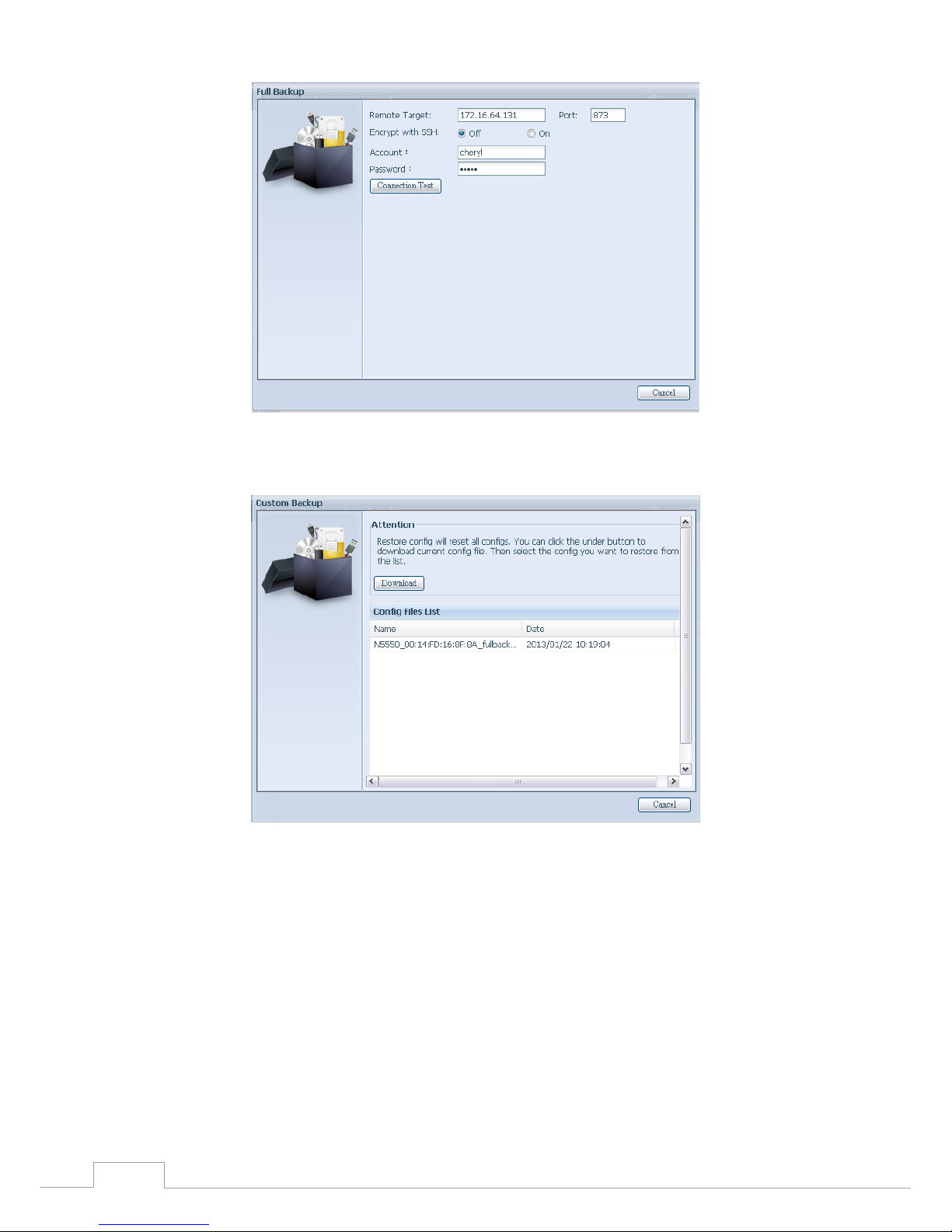
86
Chapter 3: System Administration
Click “Next” and a screen will appear as shown below. It has the listed available system 3.
configuration backup files. Select the one you want and click next. You also have the option
to download the current system configuration before restoring from the backup file.
After clicking “Next”, a screen will appear as shown below. Listed on the left hand side, you 4.
will see the configuration backup details which contain the 3 RAID volumes. On the right
hand side, you will see a list of single “ RA I D ” volume. You may roll back to previous page to
recall the example we have taken.
Page 93
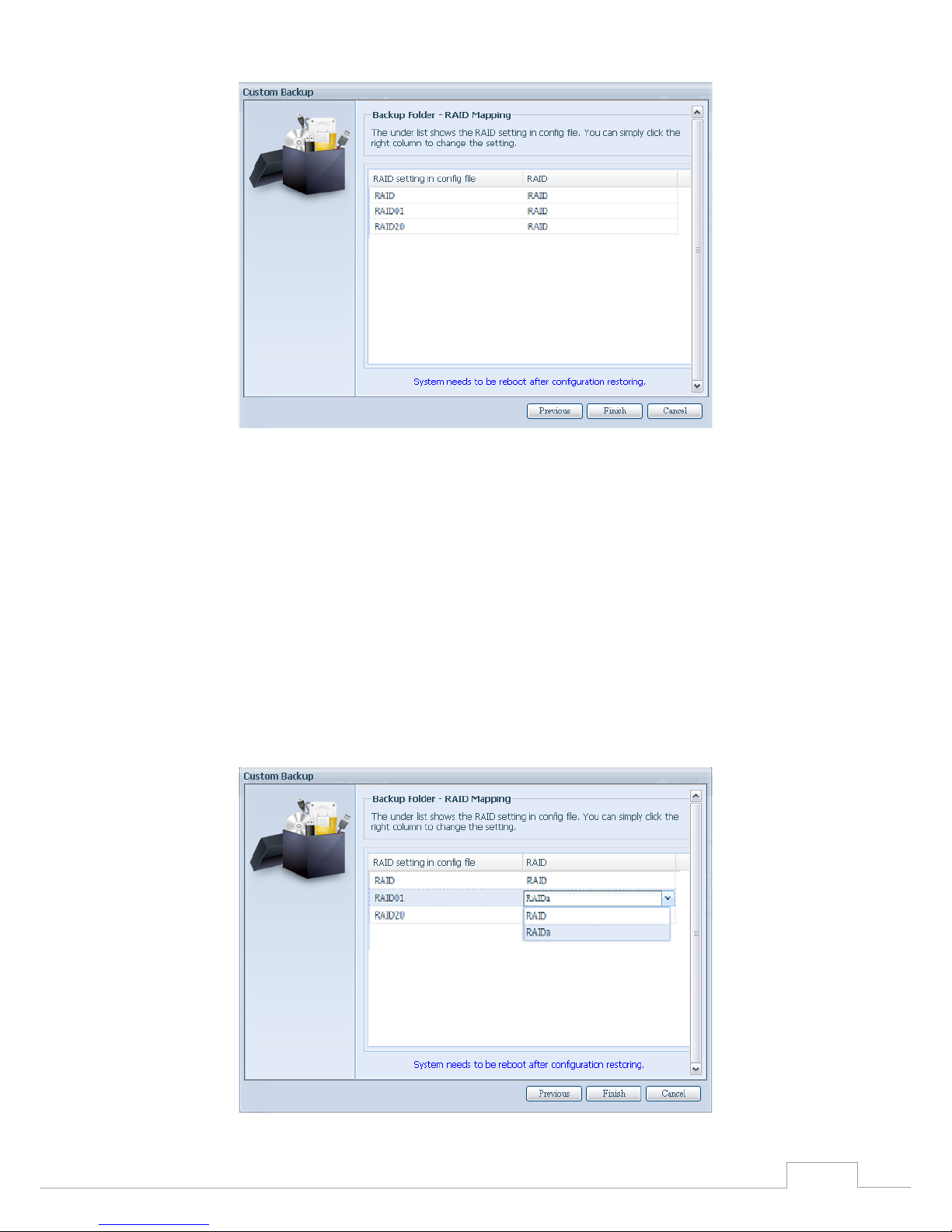
87
Chapter 3: System Administration
The backup configuration has different numbers of RAID volume than the current system (3 5.
vs 1). It can be kept as the RAID volume mapping arranged by the system, then carry on to
click “Finish”. This means that all 3 RAID volumes configuration such as share folder etc. will all
restore to the current unit in the RAID volume “RAID”.
In other circumstances, if the current unit contains 2 RAID volumes, then it can be chosen 6.
from the left hand side of system backup configuration RAID volume list which RAID volume
to map to the current system.
Let’s see the following screen to make it clearer.
The current system has 2 RAID volumes, “RAID” and “RAIDa”. Select the RAID volume from the backup
configuration volume list which is going to be mapped to the RAID volume of the current system.
Simply click on the right hand side of “RAIDa” and a drop down list will appear. Now you can choose
which volume to map with. In this case the “RAID01” volume from the system backup configuration
will be mapped to the volume “RAIDa” of the current unit. Once again, it means all the shares that
were created in the volume “RAID01” will be restored to volume “RAIDa” of the current system.
Page 94

88
Chapter 3: System Administration
Data Guard (Local Backup)3.8.3
The Thecus product provides complete backup solution between Thecus NAS systems as well as
between folders of local systems.
Remote Data backup
Item Description
Add Add a new task.
Edit Edit selected task.
Remove Remove selected task.
Start Click on start to start a scheduled scan task right away.
Stop Stop the associated running task. Also can be used if a task has been setup as real-time, clicking “Stop”
can terminate the running process. Simply click ‘Start” to re-start the real-time operation.
Restore Restore the associated task.
Log Click to view the associated task process details.
Restore NAS Configuration Click to restore the system configurations from a selected destination to a source unit.
From the Data Guard function list, select Add. The data backup setup wizard appears as below, click
on “Local Backup”:
The local backup has 6 different selection you can choose from.
Page 95

89
Chapter 3: System Administration
Local Data backup
Item Description
Import This is associated with external devices which are added to the system such as USB disk. You can select a
folder from an external device and import it to the NAS as a share folder.
Copy Copy folder to folder or NAS folder to external device or external device to NAS folder. This backup is within
folder level.
Realtime Backup The task will be executed on the fly between the source and the target. In other word, any changes made
at the source will sync to the destination immediately.
Schedule Backup The task will be executed on schedule between the source and the target.
iSCSI Backup The iSCSI volume will be backup to the destination as a single file.
iSCSI Import The iSCSI file can be imported from the iSCSI backup back to the destination as an iSCSI volume.
Import: click on “Import” and a screen will appear as below. 1.
If there is an external device installed on system such as USB disk, then it will be listed in the
Source pane.
Click on the associated external device and the contain folders will be listed. Select the folders that
are going to be imported to the NAS and select the available RAID volume which is listed in Targe t
pane.
In here, we have selected the “Intel Graphi…” and “N10850” folders from the external device and
Page 96

90
Chapter 3: System Administration
imported them to the NAS under the RAID60volume.
Next, please select the path from the drop down list to save the log. Also, give the access permission
whether these selected folders will be “Public” or not after the import.
Read the notes and check the “Accept” box for confi rmation. If a share name already exists for the im-s and check the “Accept” box for confi rmation. If a share name already exists for the im- and check the “Accept” box for confi rmation. If a share name already exists for the im-the “Accept” box for confi rmation. If a share name already exists for the im- “Accept” box for confi rmation. If a share name already exists for the im-“Accept” box for confi rmation. If a share name already exists for the im-Accept” box for confi rmation. If a share name already exists for the im-” box for confi rmation. If a share name already exists for the im-for confirmation. If a share name already exists for the im-a share name already exists for the import, then the import will be rename automatically to “existing share name -1”.
For esample, if the NAS RAID volume “RAID60” already has a folder named “Intel_Graphics_
V614105398_XP”, the import folder will then be rename to: “Intel_Graphics_V614105398_XP-1”.
Page 97

91
Chapter 3: System Administration
Now, you will see in the data guard task list that you have created a task .
And that the system has created 2 new share folders from the task just created.
Copy: click on “Copy” and this screen appears. 2.
3 different options can be selected, folder to folder, folder to external device or external
device to folder.
Page 98

92
Chapter 3: System Administration
Folder to Folder•
Folder to external device•
External device to Folder•
Page 99

93
Chapter 3: System Administration
Let’s take “Folder to External device” as an example. In the source pane, select the desired RAID
volume and its associated folder list will appear; same method in the target pane for the associated
external device.
Select a folder from the source pane which is going to be copy over, then select in target pane i t’s
destination.
Choosing the sync type, “Incremental” or ‘Sync”, and select the log path from the drop menu list.
Page 100

94
Chapter 3: System Administration
Read the notes and check the “Accept” box for confirmation.
Now, you will see in the data guard task list that you have created a task.
Realtime Backup: click on “Realtime Backup” and this screen will appear. 3.
2 different options can be selected from, folder to folder, folder to external device.
Let’s take “Folder to Folder” backup for example. Select from the source pane the folder “NAS_
Public”, then select its destination in the target panefolder “R6andy”.
 Loading...