

Page 1
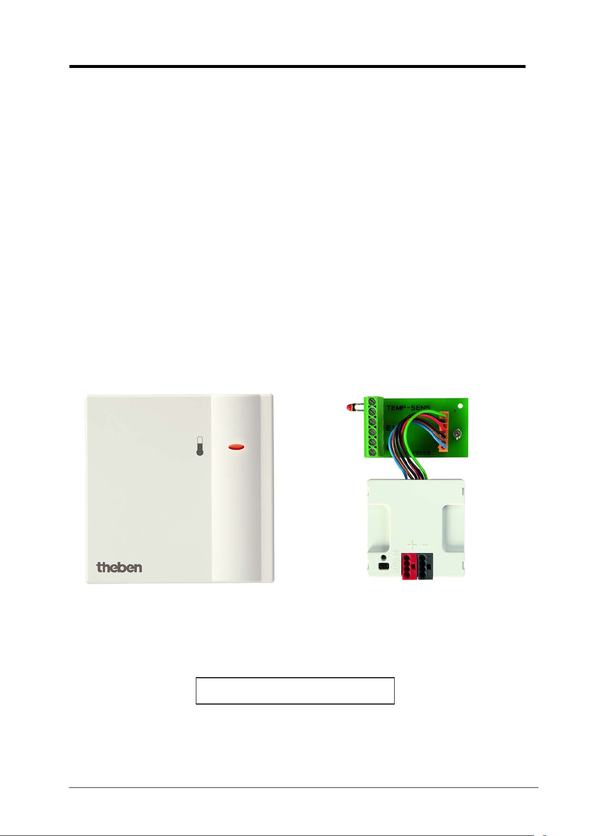
RAM 712 KNX room thermostat for surface-mounted and flush-mounted installa tion
RAM 712 KNX room thermostat for
surface-mounted
and flush-mounted installation
theben
RAM 712 712 9 200
Version: Dec-10 (subject to change) Page 1 of 65
Page 2

RAM 712 KNX room thermostat for surface-mounted and flush-mounted installa tion
theben
Contents
1 Functional characteristics ......................................................................................................... 4
1.1 Operation .......................................................................................................................... 5
1.2 Benefits of RAM 712 ....................................................................................................... 5
1.2.1 Special features ............................................................................................................ 5
2 Technical data .......................................................................................................................... 6
2.1 General ............................................................................................................................. 6
3 RAM 712 V1.0 application program ....................................................................................... 7
3.1 Selection in the product database ..................................................................................... 7
3.2 Parameter pages ................................................................................................................ 7
3.3 Communication objects .................................................................................................... 8
3.3.1 Object characteristics ................................................................................................... 8
3.3.2 Description of objects ................................................................................................. 11
3.4 Parameters ...................................................................................................................... 17
3.4.1 Settings ....................................................................................................................... 17
3.4.2 Heating control ........................................................................................................... 18
3.4.3 Setpoint values ........................................................................................................... 20
3.4.4 Actual value ................................................................................................................ 23
3.4.5 Cooling control ........................................................................................................... 24
3.4.6 Operating mode .......................................................................................................... 27
3.4.7 Cooling setpoint values .............................................................................................. 29
3.4.8 Inputs E1, E2 .............................................................................................................. 30
4 Start-up ................................................................................................................................... 41
4.1 Installation in a flush-mounted socket ........................................................................... 41
4.2 Actuators to control heating and cooling ....................................................................... 42
4.2.1 Heating control variable ............................................................................................. 42
4.2.2 Cooling control variable ............................................................................................. 42
5 Typical applications: .............................................................................................................. 43
5.1 The school environment: Heating with presence detector and frost protection via
window contact. ......................................................................................................................... 43
5.1.1 Description ................................................................................................................. 43
5.1.2 Devices: ...................................................................................................................... 43
5.1.3 Overview .................................................................................................................... 44
5.1.4 Objects and links ........................................................................................................ 45
5.1.5 Important parameter settings ...................................................................................... 46
6 Appendix ................................................................................................................................ 48
6.1 Determining the current operating mode ....................................................................... 48
6.1.1 New operating modes ................................................................................................. 48
6.1.2 Old operating modes .................................................................................................. 49
6.1.3 Determining the setpoint value .................................................................................. 50
6.2 Setpoint offset ................................................................................................................ 52
6.3 Base setpoint value and current setpoint value .............................................................. 53
6.4 The scenes ...................................................................................................................... 54
6.4.1 Principle ..................................................................................................................... 54
6.4.2 Saving scenes: ............................................................................................................ 55
6.4.3 Calling scenes: ............................................................................................................ 56
6.5 External interface ........................................................................................................... 57
6.5.1 Circuit board ............................................................................................................... 57
Version: Dec-10 (subject to change) Page 2 of 65
Page 3

RAM 712 KNX room thermostat for surface-mounted and flush-mounted installa tion
theben
6.5.2 External sensor ........................................................................................................... 58
6.5.3 Suitable actuators ....................................................................................................... 58
6.6 Temperature control ....................................................................................................... 59
6.6.1 Introduction ................................................................................................................ 59
6.6.2 Response of the P-control .......................................................................................... 60
6.6.3 Response of the PI control ......................................................................................... 61
7 Glossary .................................................................................................................................. 62
7.1 Continuous and switching control .................................................................................. 62
7.2 Hysteresis ....................................................................................................................... 62
7.2.1 Negative hysteresis: .................................................................................................... 62
7.2.2 Positive hysteresis ...................................................................................................... 63
7.3 Dead zone ....................................................................................................................... 63
7.3.1 Case 1: Heating and cooling with continuous control ................................................ 63
7.3.2 Case 2: Heating with 2-point control and cooling with continuous control ............... 64
7.3.3 Case 3: Heating with continuous control and cooling with 2-point control ............... 64
7.3.4 Case 4: Heating and cooling with 2-point control ...................................................... 64
7.3.5 Setpoint value calculation .......................................................................................... 65
Version: Dec-10 (subject to change) Page 3 of 65
Page 4

RAM 712 KNX room thermostat for surface-mounted and flush-mounted installa tion
theben
1 Functional characteristics
The RAM 712 room thermostat is a KNX controller for heating and cooling operation
with 2 binary inputs (see appendix: External interface) that can be controlled both continuously
and in 2 point operating mode.
It measures the current room temperature (actual value) via a sensor and sends either
a continuous control variable (0...100%) or a switching command (On/Off) to an actuator or
heating actuator to achieve the desired room temperature (setpoint value).
This device is primarily ideal for use in public buildings, including schools for example, thanks to
its elegant design, the absence of control elements, its robust structure and its excellent price
performance ratio.
The option of installing the device in a flush-mounted socket allows it to be integrated in
switching programmes of choice.
Using the binary inputs, switches and keys (floating) can be connected to switch, dim and control
blinds.
The blinds and dimmer channels can also be controlled with a single key (single key operation).
Possible actuators include: Cheops drive, HMG 4, HMT 6, HMT 12
The RAM 712 has four operating modes that allow setpoint values to be easily adapted to
requirements for living comfort and saving energy:
• Comfort
• Standby
• Night mode
• Frost protection mode
A setpoint value is assigned to each operating mode.
Comfort mod e is used when the room is occupied
The setpoint value is reduced slightly in standby mode. This operating mode is used when the
room is not occupied but is expected to be shortly.
The setpoint value is drastically reduced in night mode as the room is not expected to be
occupied for several hours.
In frost protection mode, the room is controlled to a temperature that eliminates the risk of
damage to the radiators caused by freezing due to low outdoor temperatures.
This may be required for 2 reasons:
- The room is not occupied for several days.
- A window has been opened and no further heating is required for the time being.
The operating modes are usually controlled by a timer.
However, a presence detector and/or presence keys and window contacts are recommended for
optimum control.
See Determining the setpoint value chapter.
Version: Dec-10 (subject to change) Page 4 of 65
Page 5

RAM 712 KNX room thermostat for surface-mounted and flush-mounted installa tion
1.1 Operation
RAM 712 has no control elements. All parameters are preset via ETS.
Operating mode and setpoint value specification can be controlled via the bus;
see Object characteristics.
1.2 Benef its of RAM 712
• Continuous P / PI or switching room thermostat
• Temperature sensor can be sited as required
• Operating mode change via presence and window objects
• Heating and cooling operation
• Infinite regulation through continuous actuating value
• 2 binary inputs for conventional keys/switches or
for blinds / dimmer control
• Adjustable effect with binary inputs
• Blinds and dimmers can also be controlled using single key operation
theben
1.2.1 Special features
• The absence of control elements is primarily suited to public buildings, for example
schools.
• Very small dimensions; can be installed in a flush-mounted socket
• Single key operation allows the 2 external connections to control one set of blinds or a
dimmer
• Both external connections can be used for LED control if required.
Version: Dec-10 (subject to change) Page 5 of 65
Page 6

RAM 712 KNX room thermostat for surface-mounted and flush-mounted installa tion
Power supply:
Bus voltage.
Permitted operating temperature:
-5 °C ... + 45°C
Current draw from bus voltage:
Max 10 mA
Bus connection:
Bus terminal
Protection class:
III in accordance with EN 60730-1
Protection rating:
IP 20 in accordance with EN 60529
Dimensions:
LxWxH 74 x 74 x 28 (mm)
Inputs
Contact voltage:
3.3 V internal provided
Contact current:
0.1 mA
Maximum line length:
5 m
2 Technical data
2.1 General
theben
Version: Dec-10 (subject to change) Page 6 of 65
Page 7
RAM 712 KNX room thermostat for surface-mounted and flush-mounted installa tion
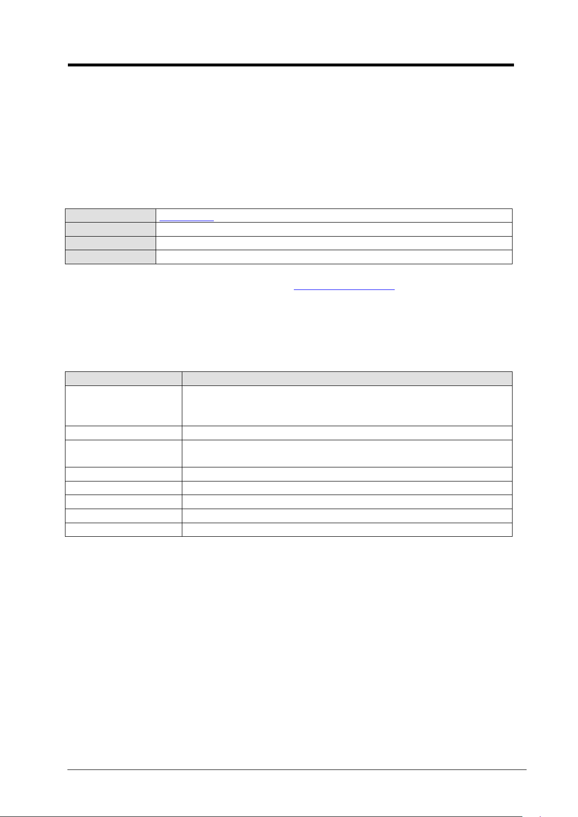
Manufacturer
Theben AG
Product family
Heating, ventilation, air conditioning
Product type
Continuous and 2 point controller
Program name
RTR RAM 712 UP
Function
Description
Settings
Selection of control functions,
Setpoint values
Setpoint value after download, values for night, frost mode etc.
Cooling setpoint
values
Dead zone and temperature increases conditional on the operating
mode
Actual value
Send actual value, calibration
Heating control
Type of control, heating parameters etc.
Cooling control
Type of control, cooling parameters etc.
Operating mode
Operating mode after reset, presence sensor
Input E1 .. E2
Function of connected contacts, switches, dimmers, blinds.
3 RAM 712 V1.0
application program
3.1 Sel e c ti on in the product database
The ETS database can be found on our website: http://www.theben.de
3.2 Parameter pages
theben
Table 1
Standard and user-defined settings, activation of the external
interface
Version: Dec-10 (subject to change) Page 7 of 65
 Loading...