

Page 1

MIX 2 series RMG 4 U / RME 4 U actuators
RMG 4 U 4930223
RME 4 U 4930228
MIX 2 series actuators
RMG 4 U / RME 4 U
Updated: Apr-15 (Subject to changes) Page 1 of 50
Page 2

MIX 2 series RMG 4 U / RME 4 U actuators
Contents
1 Functional characteristics ................................................................................................ 4
2 MIX and MIX2 devices ..................................................................................................... 5
3 Operation ........................................................................................................................... 6
4 Technical data ................................................................................................................... 7
5 The application programme "MIX2 V1.8" ..................................................................... 8
5.1 Selection in the product database ........................................................................... 8
5.2 Communication objects ........................................................................................... 9
5.2.1 Channel-related objects: ......................................................................................... 9
5.2.2 Common objects: .................................................................................................. 12
5.2.3 Description of objects ........................................................................................... 13
5.3 Parameter ................................................................................................................ 20
5.3.1 Parameter pages .................................................................................................... 20
5.3.2 Parameter description ........................................................................................... 21
5.3.2.1 The "General" parameter page ..................................................................... 21
5.3.2.2 The "RMG 4 U basic module" parameter page ............................................ 23
5.3.2.3 The "RMG 4 U channel Cx: Configuration options" parameter page .......... 24
5.3.2.4 The "Contact characteristics" parameter page ............................................ 26
5.3.2.5 The "On/Off delay" parameter page ............................................................. 27
5.3.2.6 The "Pulse function.." parameter page ......................................................... 27
5.3.2.7 The "Staircase light with forewarning function .." parameter page ............. 28
5.3.2.8 The "Flashing.." parameter page .................................................................. 29
5.3.2.9 The "Threshold" parameter page .................................................................. 30
5.3.2.10 The "Block function" parameter page ....................................................... 32
5.3.2.11 The "Scenes" parameter page ................................................................... 33
5.3.2.12 The "Feedback" parameter page .............................................................. 36
5.3.2.13 The "Hour counter and service" parameter page ..................................... 37
5.3.2.14 The "Link" parameter page ....................................................................... 39
6 Typical applications ......................................................................................................... 40
6.1 2x switching with push button interface .............................................................. 40
6.1.1 Devices: ................................................................................................................ 40
6.1.2 Overview .............................................................................................................. 40
6.1.3 Objects and links .................................................................................................. 40
6.1.4 Important parameter settings ................................................................................ 41
6.2 Switching light with service counter and display ................................................ 42
6.2.1 Devices ................................................................................................................. 42
6.2.2 Overview .............................................................................................................. 42
6.2.3 Objects and links .................................................................................................. 43
6.2.4 Important parameter settings ................................................................................ 44
6.3 Simple warning function with flashing light ........................................................ 45
6.3.1 Devices: ................................................................................................................ 45
Updated: Apr-15 (Subject to changes) Page 2 of 50
Page 3

MIX 2 series RMG 4 U / RME 4 U actuators
6.3.2 Overview .............................................................................................................. 45
6.3.3 Objects and links .................................................................................................. 45
6.3.4 Important parameter settings ................................................................................ 46
7 Appendix .......................................................................................................................... 47
7.1 The scenes ................................................................................................................ 47
7.1.1 Principle ............................................................................................................... 47
7.1.2 Call up or save scenes: ......................................................................................... 48
7.1.3 Teach in scenes without telegrams (MIX2 devices ONLY) ................................ 50
7.2 Conversion of percentages to hexadecimal and decimal values ......................... 50
Updated: Apr-15 (Subject to changes) Page 3 of 50
Page 4

MIX 2 series RMG 4 U / RME 4 U actuators
1 Functional characteristics
• MIX2 4-way switch actuator.
• MIX2 basic module.
• Can be upgraded to a maximum of 12 channels.
• Up to 2 MIX or MIX2 extension modules can be connected to a basic module.
• Device and KNX bus module can be swapped independently of each other.
• Removable KNX bus module enables devices to be changed without reprogramming.
• Manual set-up and use of switch actuators is also possible without KNX bus module.
• LED switching status indicator for each channel.
• Manual operation on device (even without bus voltage).
• Adjustable features: e.g. switching, delayed switching, pulse function.
• Links, type of contact (NC contact/NO contact) and participation in central commands such
as permanent On, permanent Off, central switching, and save/call up scene.
• Switch functions: e.g. On/Off, pulse, On/Off delay, staircase light with forewarning.
• Logical links: e.g. block, AND, release, OR.
• Activation of the channel function via 1-bit telegram or 8-bit threshold.
Updated: Apr-15 (Subject to changes) Page 4 of 50
Page 5
MIX 2 series RMG 4 U / RME 4 U actuators
MIX2 basic
493…
RMG 4 I, RMG 4 U,
BMG 6 T
MIX2
493…
RME 4 I, RME 4 U,
6 T.
MIX basic
491…
BMG 6, DMG 2 S, HMG 4,
RMG 4 C-load, SMG 2 S
MIX extensions
491…
BME 6, DME 2 S, HME 4,
RME 4 C-load, SME 2 S
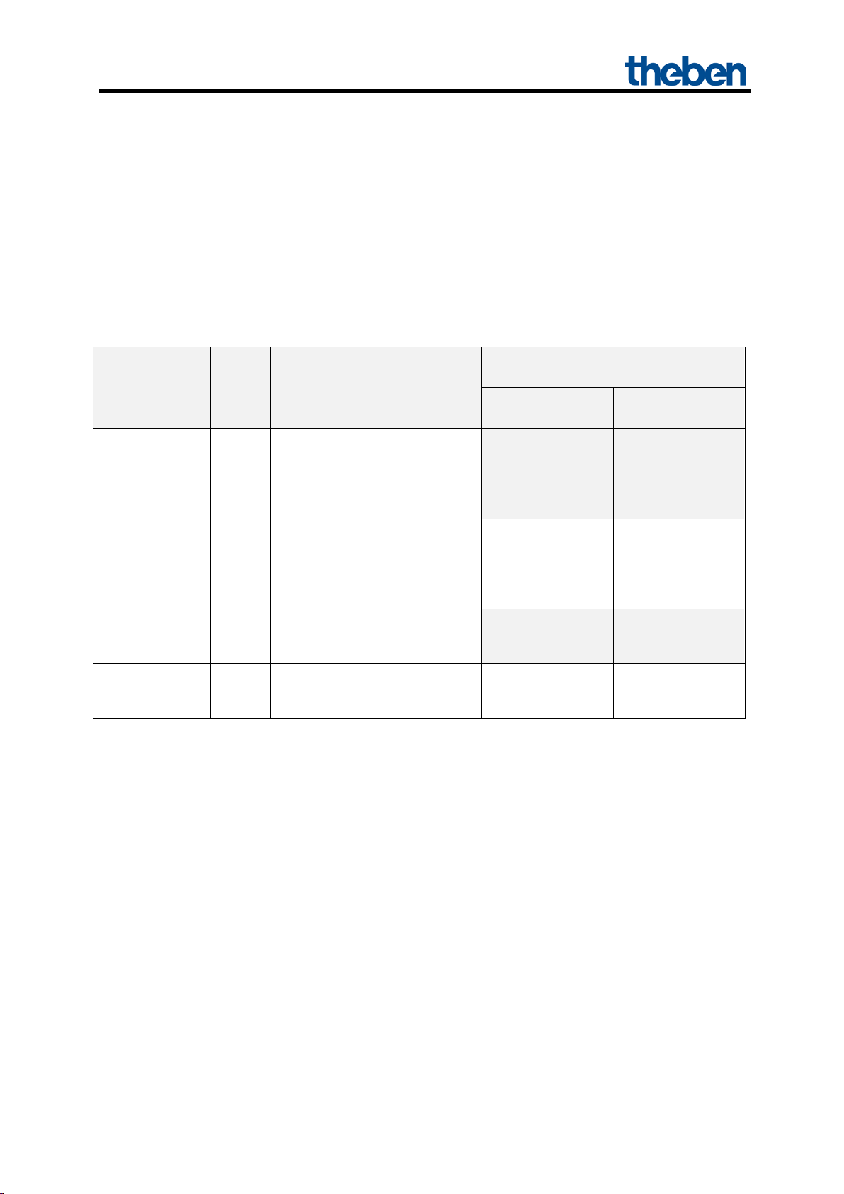
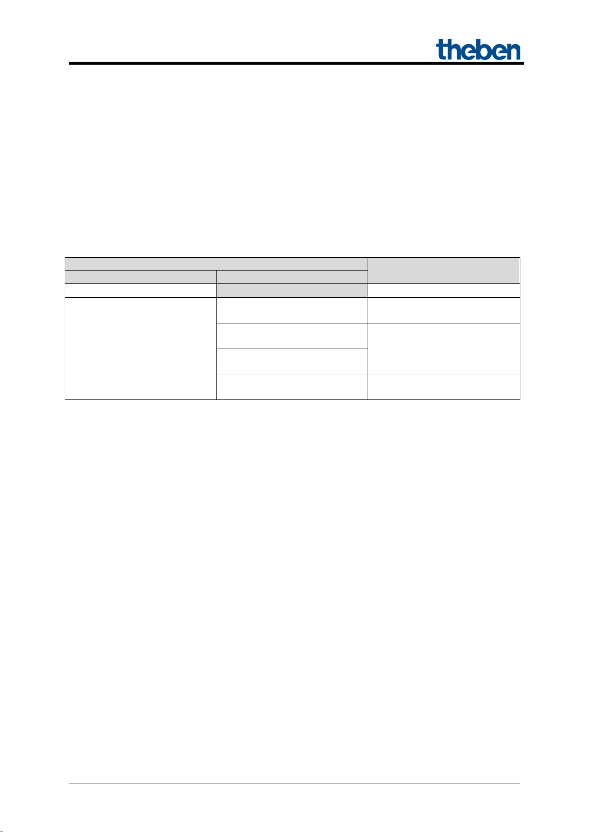
2 MIX and MIX2 devices
The MIX2 series consists of the basic modules RMG 4 I, RMG 4 U, RMG 8 S, RMG 8 T, DMG 2 T,
JMG 4 T, JMG 4 T 24V, HMG 6 T, BMG 6 T + extensions RME 4 I,
RME 4 U, RME 8 S, RME 8 T, DME 2 T, JME 4 T, JME 4 T 24V, HMG 6 T, BME 6 T (as of
03/2015).
Any MiX and MIX2 extension modules can be connected to a MIX2 basic module.
Table 1
Device type
modules
extensions
modules
* Adjusted parameter display and object numbering.
Ord.
No.
Designation
RMG 8 S, RMG 8 T,
DMG 2 T, JMG 4 T,
HMG 6 T, JMG 4 T 24V,
RME 8 S, RME 8 T,
DME 2 T, JME 4 T,
HME 6 T, JME 4 T 24V, BME
JMG 4 S, RMG 4 S,
JME 4 S, RME 4 S,
Can be used with basic module..
in the MIX series
- -
no Yes
- -
yes Yes*
in the MIX2
series
Updated: Apr-15 (Subject to changes) Page 5 of 50
Page 6

MIX 2 series RMG 4 U / RME 4 U actuators
3 Operation
Each channel can be switched on and off independently of all parameters using the buttons on the
device. A status LED displays the current switching status.
All bus telegrams are ignored with manual operation switched on (manual button) and the channels are
exclusively to be operated via the buttons.
Mains voltage is required for the functioning of the buttons and LEDs, bus voltage or bus module are
not required.
Updated: Apr-15 (Subject to changes) Page 6 of 50
Page 7

MIX 2 series RMG 4 U / RME 4 U actuators
KNX operating voltage
Bus voltage, ≤ 4 mA
Operating voltage
110 – 240 V AC
Frequency
50 – 60 Hz
Standby output
0.3 W
Type of installation
DIN-rail
Width
4 TE
Connection type
KNX bus terminal
Solid: 0.5 mm² (Ø 0.8) to 4 mm² | strand with
crimp terminal: 0.5 mm² to 2.5 mm²
Number of channels
4
Contact gap
< 3 mm
Voltage output
240 V AC
Switch output
Floating
Switching of different phases
Possible
Type of contact
16 A, 3 A NO contact
Resistive load
3680 W
Incandescent and halogen lamp load
2000 W
Fluorescent lamp load (KVG)
parallel-corrected
Fluorescent lamp load (KVG) not
corrected
Fluorescent lamp load (EB)
1200 W
Energy-saving lamps
300 W
LED lamps
< 2 W = 55 W or > 2 W < 8 W = 180 W
Suitable for SELV
Yes, if all channels switch SELV
Ambient temperature
-5 °C … +45 °C
Protection rating
IP 20
Protection class
II in accordance with EN 60 730-1
4 Technical data
Max. cable cross-section
1300 W (140 μF)
2000 VA
Updated: Apr-15 (Subject to changes) Page 7 of 50
Page 8

MIX 2 series RMG 4 U / RME 4 U actuators
Manufacturer
Theben AG
Product family
Output
Product type
RMG 4 U
Program name
MIX2 V1.8
Number of communication objects:
254
Number of group addresses:
254
Number of associations:
255
5 The application programme
"MIX2 V1.8"
5.1 Selection in the product database
The ETS database can be found on our downloads page: www.theben.de/en/downloads_en.
Table 2
Updated: Apr-15 (Subject to changes) Page 8 of 50
Page 9

MIX 2 series RMG 4 U / RME 4 U actuators
Type
Flags
C R W
T
1 bit
1,001
1 byte
5,001
1 byte
5,010
Threshold EIS 5
(DPT9.xxx)
2 byte
9.xxx
2 byte
7,001
1 bit
1,001
1 bit
1,001
1 bit
1,001
1 bit
1,003
1 byte
18,001
Block scenes = 1
1 bit
1,003
Enable scenes = 1
1 bit
1,001
2 byte
7,001
2 byte
7,001
1 bit
1,001
C R W
T
5.2 Communication objects
The objects are divided into channel-related and common objects
5.2.1 Channel-related objects:
Table 3:
No. Object name Function
Switch object
Threshold as percent
0 RMG 4 U channel C1
1 RMG 4 U channel C1
2 RMG 4 U channel C1 Block
3 RMG 4 U channel C1 Call up/save scenes
4 RMG 4 U channel C1
Threshold 0..255
Threshold 0..65535
Logic input in AND gate
Logic input in OR gate
Logic input in XOR gate
DPT
5 RMG 4 U channel C1 Feedback On/Off
Time to next service
6 RMG 4 U channel C1
Operating hours feedback
7 RMG 4 U channel C1 Service required
Updated: Apr-15 (Subject to changes) Page 9 of 50
Page 10
MIX 2 series RMG 4 U / RME 4 U actuators
Type
Flags
C R W
T
2 bit
2,001
1 bit
1,001
1 bit
1,001
9
Not used
10..
198
Continuation:
No. Object name Function
Switching with priority
8 RMG 4 U channel C1
Channels C2 .. C4 and extension modules: See next table.
Reset service
Reset operating hours
DPT
Updated: Apr-15 (Subject to changes) Page 10 of 50
Page 11
MIX 2 series RMG 4 U / RME 4 U actuators
BASIC MODULE: RMG 4 U
C2 C3
10 20
11 21
12 22
13 23
4
14
24
34
15 25
16 26
17 27
18 28
C1
C2
C3
C4
80
90
100
110
81
91
101
111
82
92
102
112
83
93
103
113
84
94
104
114
85
95
105
115
86
96
106
116
87
97
107
117
88
98
108
118
2nd EXTENSION: RME 4 U
C1
C2
C3
C4
160
170
180
190
161
171
181
191
162
172
182
192
163
173
183
193
164
174
184
194
165
175
185
195
166
176
186
196
167
177
187
197
168
178
188
198
Table 4: Overview of channel-related objects
C1
0
1
2
3
5
6
7
8
C4
30
31
32
33
35
36
37
38
1st EXTENSION: RME 4 U
Updated: Apr-15 (Subject to changes) Page 11 of 50
Page 12
MIX 2 series RMG 4 U / RME 4 U actuators
Type
Flags
C R W T 78
RMG 4 U
158
EM1 RME 4 U
238
EM2 RME 4 U
RMG/E4x/8x,DMG/E2x,
SME2S
1 bit
1,001
RMG/E4x/8x,DMG/E2x,
SME2S
1 bit
1,001
RMG/E4x/8x,DMG/E2x,
SME2S
1 bit
1,001
RMG4x/8x,DMG/E2x,
JMG/E4x,SME2S
1 byte
18,001
1 bit
1,001
1 bit
1,001
1 bit
1,001
1 bit
1,008
1 bit
1,002
1 bit
1,002
14 byte
16,001
14 byte
16,001
14 byte
16,001
14 byte
16,001
C R W
T
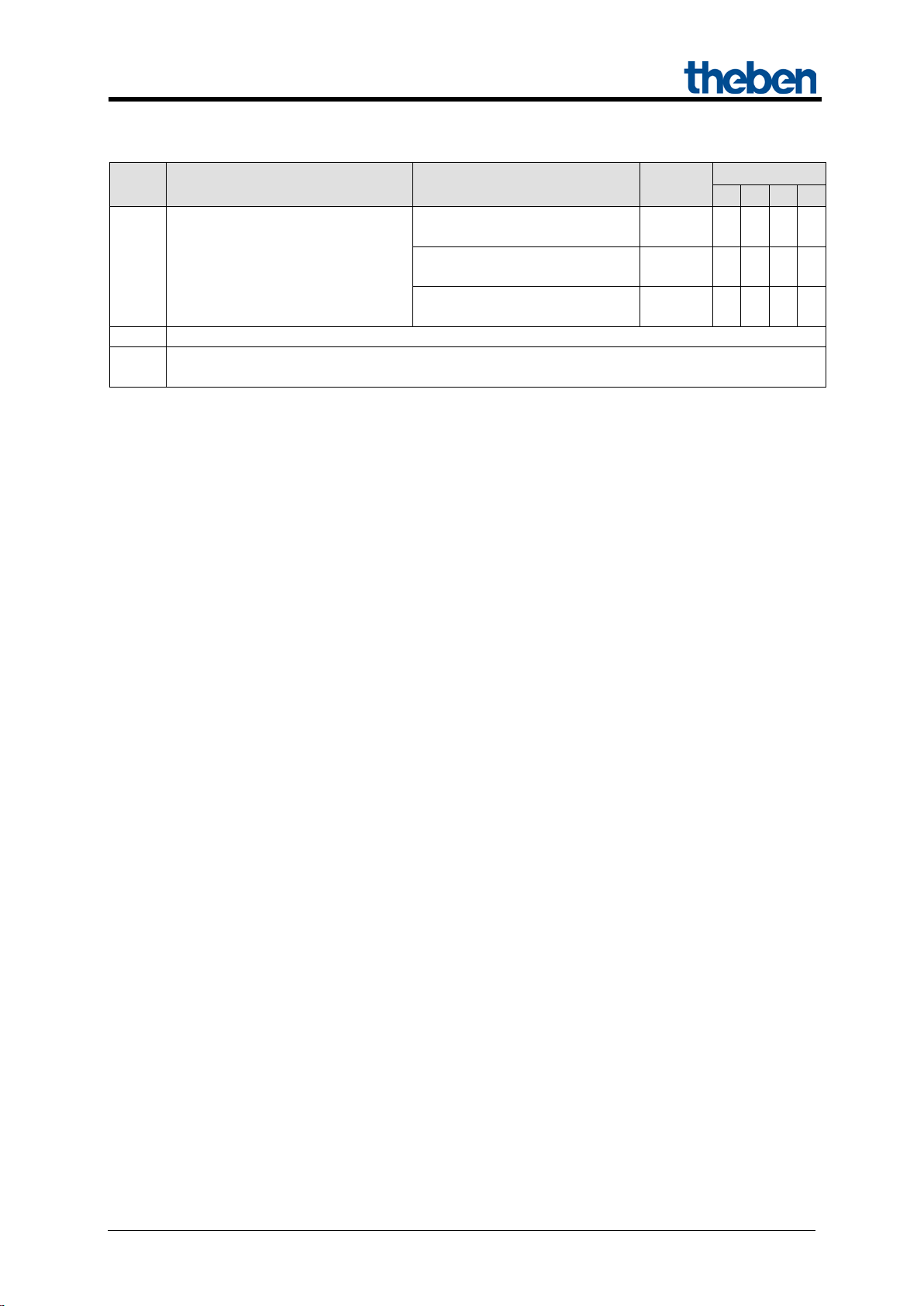
5.2.2 Common objects:
These objects are partly used by the basic module and the two extension modules.
Table 5:
No. Object name Function
Manual
240 Central continuous ON
241 Central continuous OFF
242 Central switching
243 Call up/save central scenes
244 Central safety 1 For JME 4 S
245 Central safety 2 For JME 4 S
246 Central safety 3 For JME 4 S
247 Central up/down For JME 4 S
248 Central safety rain For JMG 4 T
DPT
1 bit
1,001
249 Central safety frost For JMG 4 T
250 Version of bus coupling unit transmit
251 Version of basic module transmit
252 Version of 1st extension module transmit
253 Version of 2nd extension module transmit
Updated: Apr-15 (Subject to changes) Page 12 of 50
Page 13
MIX 2 series RMG 4 U / RME 4 U actuators
Parameter
Activation of channel function
via
Activation of function via
Type of threshold object
Switch object
1-bit telegram
Object type: Percent (DPT
5.001)
Object type: Counter value
0..255 (DPT 5.010)
Object type: Counter value
0..65535 (DPT 7.001)
Object type: EIS5 e.g. CO2,
brightness (DPT 9.xxx)
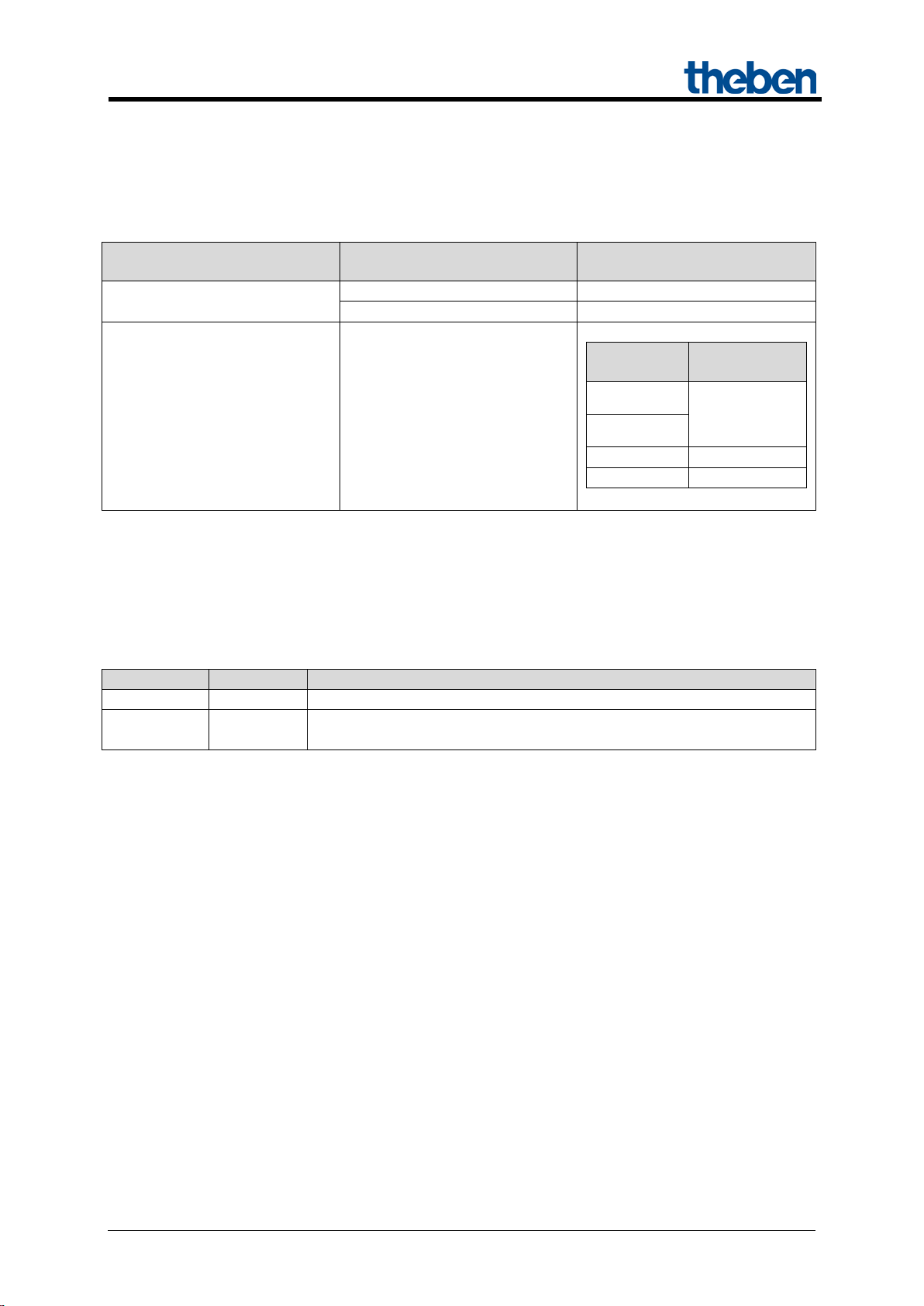
5.2.3 Description of objects
• Object 0 "Switch object, threshold as percent, threshold 0..255, threshold EIS 5
(DPT 9.xxx), threshold 0..65535 "
This object activates the set channel function (see parameter: Channel function).
The set channel function can either be activated via 1-bit telegram or by exceeding a threshold (8- or
16-bit telegram).
Table 6:
Exceeding percentage value
Exceeding the threshold
• Object 1 "Logic input in AND gate, in OR gate, in XOR gate"
Only availab le if Link is activated (Configuration options parameter page).
Forms a logical link together with object 0 to activate the channel function.
• Object 2 "Block"
Locks the channel function.
Responses to setting and cancelling the block can be configured if the block function has been
activated (Configuration options pa rameter page).
Any value in given numerical
range
2 byte floating-point number
Updated: Apr-15 (Subject to changes) Page 13 of 50
Page 14

MIX 2 series RMG 4 U / RME 4 U actuators
• Object 3 "Call up/save scene"
Only available if the scene function has been ac tivate d (Configuration options parameter page).
This object can be used to save and subsequently call up scenes.
Saving stores the channel status.
It does not matter how this status is produced (whether via switch commands, central objects or the
buttons on the device).
The saved status is restored when it is called up.
All scene numbers from 1 to 64 are supported.
Each channel can participate in up to 8 scenes.
See appendix: Scenes
• Object 4 "Block scenes = 1, Enable scenes = 1"
Locks the scene function with a 1 or a 0 depending on the configuration.
As long as it is blocked, scenes cannot be saved or called up.
• Object 5 "On/Off feedback"
Reports the current channel status.
The status can also be fed back inverted depending on configuration.
• Object 6 "Time to next service, operating hours feedback "
Only available if the hour counter function
has been activated (Configuration options parameter page).
Reports, depending on selected Type of hour counter (Hour counter and service param eter pag e),
either the remaining period to the next service or the current status of the hour counter.
• Object 7 "Service required"
Only available if the hour counter function has been activated (Configuration options parameter page)
and Type of hour counter = Counter for time to next service.
Reports if the next service is due.
0 = not due
1 = service is due.
Updated: Apr-15 (Subject to changes) Page 14 of 50
Page 15
MIX 2 series RMG 4 U / RME 4 U actuators
Activate hour counter
Reset service*
Reset service interval counter.
Reset operating hours*
Reset hour counter
Priority control:
Status of
object 8
2
OFF
3
ON
Telegram
Meaning
Explanation
0
Auto
All channels can be operated via the bus as well as via the buttons.
The channels can only be operated via the buttons on the device. Bus
telegrams will not work.
• Object 8 "Switching with priority, reset service, reset operating hours"
The function of the object depends on whether or not the hour counter function has been activated
(Configuration options parameter page).
Function Use
yes
Channel status
0
no Switching with priority
1
as set by
object 0
* Depending on configuration.
• Objects 78, 158, 238 "Manual"
Only available for devices in the MIX2 series (order number 493…)
Puts the relevant module in manual mode or sends the status of the manual operation.
1 Manual
The duration of the manual mode, i.e. the Function of the manual button can be configured on the
General parameter page.
Updated: Apr-15 (Subject to changes) Page 15 of 50
Page 16

MIX 2 series RMG 4 U / RME 4 U actuators
• Object 240 "Central permanent ON"
Central switch-on function.
Enables simultaneous switch on of all channels (basic and extension modules) with a single telegram.
0 = No function
1 = Permanent ON
Participation in this object can be set individually for each channel (Configuration options parameter
page).
IMPORTANT:
This object takes top priority.
As long as it is set, the other switch commands will not work on the participating channels.
Works on the following devices:
RMG 4 U / RME 4 U, RMG 4 I / RME 4 I, RMG 8 S / RME 8 S, RMG 8 T / RME 8 T,
RME 4 S / C-load, DMG 2 T, DME 2 S/T, SME 2 S.
• Object 241 "Central permanent OFF"
Central switch-off function.
Enables simultaneous switch off of all channels (basic and extension modules) with a single telegram.
0 = No function
1 = Permanent OFF
Participation in this object can be set individually for each channel (Configuration options parameter
page).
IMPORTANT: This object has the second highest priority after Central permanent ON. As long as it
is set, the other switch commands will not work on the participating channels.
Works on the following devices:
RMG 4 U / RME 4 U, RMG 4 I / RME 4 I, RMG 8 S / RME 8 S, RMG 8 T / RME 8 T,
RME 4 S / C-load, DMG 2 T, DME 2 S/T, SME 2 S.
Updated: Apr-15 (Subject to changes) Page 16 of 50
Page 17

MIX 2 series RMG 4 U / RME 4 U actuators
• Object 242 "Central switching"
Central switch function.
Enables simultaneous switch on or off of all channels (basic and extension modules) with a single
telegram.
0 = OFF
1 = ON
Participation in this object can be set individually for each channel (Configuration options parameter
page).
With this object, every participating channel responds exactly as if its 1st object
(i.e. obj. 0, 10, 20, etc.) were receiving a switch command.
Works on the following devices:
RMG 4 U / RME 4 U, RMG 4 I / RME 4 I, RMG 8 S / RME 8 S, RMG 8 T / RME 8 T,
RME 4 S / C-load, DMG 2 T, DME 2 S/T, SME 2 S.
• Object 243 "Call up/save central scenes"
Central object for using scenes.
This object can be used to save and subsequently call up "scenes".
Works on the following devices:
RMG 4 I / RME 4 I, RMG 4 U / RME 4 U, RMG 8 S / RME 8 S, RMG 8 T / RME 8 T, DMG 2 T /
DME 2 T, JMG 4 T / JME 4 T, RME 4 S / C-load, DME 2 S, SME 2 S, JME 4 S
See appendix: Scenes
• Objects 244 - 249
Not used.
Updated: Apr-15 (Subject to changes) Page 17 of 50
Page 18

MIX 2 series RMG 4 U / RME 4 U actuators
Code
Meaning
xx
00 .. FF = Version of application without dividing point (17 = V1.7, 18 = V1.8 etc).
yy
Hardware version 00..99
zzz
Firmware version 000..999
Code
Meaning
xx
01 .. FF = Module code (hexadecimal).
yy
Hardware version 00..99
zzz
Firmware version 000..999
• Object 250 "Version of bus coupling unit"
For diagnostic purposes only.
Sends the bus coupling unit software version after reset or download.
Can also be read out via the ETS.
Format: Axx Hyy Vzzz
EXAMPLE: A18 H25 V025
- ETS application version 1.8
- Hardware version $25
- Firmware version $25
• Object 251 "Version of basic module"
For diagnostic purposes only.
Only for basic modules in the MIX2 series (order number 493…).
Sends the software version (firmware) of the basic module after reset or download.
Can also be read out via the ETS.
The version is issued as an ASCII character string.
Format: Mxx Hyy Vzzz
EXAMPLE: M18 H25 V025
- Module $18 = RMG 4 U
- Hardware version V25
- Firmware version V25
Updated: Apr-15 (Subject to changes) Page 18 of 50
Page 19

MIX 2 series RMG 4 U / RME 4 U actuators
Module
Code
Module or mains voltage are unavailable.
$00
RMG 8 S
$11
RMG 4 I
$12
DMG 2 T
$13
JMG 4 T/JMG 4 T 24V
$14
HMG 6 T
$15
RMG 8 T
$17
RMG 4 U
$18
BMG 6 T
$92
Module
Code
Module or mains voltage are unavailable.
$00
RME 8 S
$11
RME 4 I
$12
DME 2 T
$13
JME 4 T/JME 4 T 24V
$14
HME 6 T
$15
RME 8 T
$17
RME 4 U
$18
BME 6 T
$92
Possible module codes (as of 03/2015)
• Object 252 "Version of 1st extension module"
Telegram format: See above, object 251
Possible module codes (as of 03/2015)
• Object 253 "Version of 2nd extension module"
See above, object 252
Updated: Apr-15 (Subject to changes) Page 19 of 50
Page 20

MIX 2 series RMG 4 U / RME 4 U actuators
Function
Description
General
Selection of modules and central parameters.
BASIC MODULE:
RMG 4 U
General parameters for the basic module: Collective feedback and relay
switch delay.
RMG 4 U channel Cx
configuration options
Characteristics of channel and activation of additional functions (scenes,
links, etc.).
Contact characteristics
Type of contact and status after download, bus failure etc.
Threshold
Settings for triggering channel function through exceeding threshold.
Block function
Type of block telegram and response to blocking.
Scenarios
Selection of scene numbers relevant to the channel.
Feedback
Status of feedback object etc.
Hour counter and
service
Type of hour counter and, if required, service interval etc.
Link
Selection of logical link.
5.3 Parameter
5.3.1 Parameter pages
Table 7
Updated: Apr-15 (Subject to changes) Page 20 of 50
Page 21

MIX 2 series RMG 4 U / RME 4 U actuators
Designation
Values
Description
Type of basic module
Select device..
HMG 6 T..
Selection of available basic module
Type of 1st extension
not available/inactive
HME 4..
Selection of 1st extension module, if
Type of 2nd extension
not available/inactive
HME 4..
Selection of 2nd extension module, if
Time for cycl. sending of
2 minutes, 3 minutes,
5 minutes, 10 minutes,
60 minutes
This parameter is used exclusively for
5.3.2 Parameter description
Settings that lead to the display of other pages or functions are identified by .. .
Example: Pulse function..
5.3.2.1 The "General" parameter page
module
module
RMG 8 S..
RMG 8 T..
RMG 4 I..
RMG 4 U..
DMG 2 T..
JMG 4 T/JMG 4 T 24V..
RME 8 S..
RME 8 T..
RME 4 I..
RME 4 U..
DME 2 T..
JME 4 T/JME 4 T 24V..
HME 6 T..
RME 4 S/RME 4 C-load..
DME 2/SME 2..
BME 6..
JME 4 S..
RME 8 S..
RME 8 T..
RME 4 I..
RME 4 U..
DME 2 T..
JME 4 T/JME 4 T 24V..
HME 6 T..
RME 4 S/RME 4 C-load..
DME 2/SME 2..
BME 6..
JME 4 S..
(MIX2 series only)
available.
(MIX or MIX2 series)
available.
(MIX or MIX2 series)
feedback obj.
(MIX series, order no.
491...)
Updated: Apr-15 (Subject to changes) Page 21 of 50
15 minutes, 20 minutes
30 minutes, 45 minutes
MIX series extension modules.
(DME 2 S, SME 2, JME 4 S, BME 6
RME 4 S/C-load, and HME 4)
Page 22

MIX 2 series RMG 4 U / RME 4 U actuators
Designation
Values
Description
Function of manual
applies for 24 hours or until
applies for 30 minutes or until
applies for 1 hour or until reset
2 hours or until
reset via object
Determines how long the device works
Manual operation of
493...)
unblocked
The channels can be operated via the
buttons on the device.
blocked
No manual operation, the buttons on the
device are blocked..
Continuation:
button (MIX2 series,
order no. 493...)
channels
(MIX2 series, order no.
reset via object
blocked
applies until reset via object
reset via object
via object
applies for 2 hours or until reset
via object
applies for 4 hours or until reset
via object
applies for 8 hours or until reset
via object
applies for 1
manually and how this is ended.
In manual mode, the channels can only
be switched on and off via the buttons
on the device.
See also: object_78
This parameter is used exclusively for
MIX2 series devices.
Updated: Apr-15 (Subject to changes) Page 22 of 50
Page 23

MIX 2 series RMG 4 U / RME 4 U actuators
Designation
Values
Description
Relay switch delay
This parameter sets the minimum delay
None
There is no added delay.
60 ms
When a relay switches on, the next one
C1.
5.3.2.2 The "RMG 4 U basic module" parameter page
between switching on 2 relays if several
are activated at the same time.
The shortest delay is achieved by using
the central switch object (object 242).
When switching on via individual
telegrams (1 telegram per channel), the
bus running times and the sequential
processing of commands cause an
additional delay.
This can help avoid high current peaks
when devices are switched on
simultaneously (e.g. with a number of
lighting strips).
100 ms
200 ms
can only switch on after the set delay is
completed.
The switch-on delay between the first
and last relay is calculated according to
the following formula:
(Number of channels – 1) x delay
Example:
RMG 4 U and 60 ms:
= (4 channels – 1) * 60 ms = 180 ms
Channel C4 switches 180 ms after
Updated: Apr-15 (Subject to changes) Page 23 of 50
Page 24

MIX 2 series RMG 4 U / RME 4 U actuators
Designation
Values
Description
Copy main parameters
For channels C2..C4 only.
Yes
The following parameter settings are
no
No settings are taken from C1.
Channel function
Switching On/Off..
Staircase light timer switch with
Flashing..
Determines the basic functionality of the
Activation of function via
Switch object
The channel is operated via a 1-bit
Exceeding the threshold
The channel is operated through
page
Adjust block function
Yes..
The block function can be individually
no
The block function works with the
- When cancelling: Update.
Activate scenes
Yes..
no
Should scenes be used?
5.3.2.3 The "RMG 4 U channel Cx: Configuration options" parameter page
Table 8
from channel C1
On/off time delay..
Pulse function..
forewarning function..
The copy function simplifies the
configuration of identical channels by
many settings only having to be entered
on the 1st channel.
taken directly from channel C1:
- Channel function
- Adjust block function
- Participation in central objects
- Adjust feedback
channel.
object.
exceeding a 1 or 2-byte threshold.
See below: The „Threshold“ parameter
adjusted.
The relevant parameter page is shown.
standard parameters:
- Block with ON telegram
- When setting the block: Unchanged
Updated: Apr-15 (Subject to changes) Page 24 of 50
Page 25

MIX 2 series RMG 4 U / RME 4 U actuators
Designation
Values
Description
Participation in central
no
Central objects are not taken into
at Central switching, Permanent
and permanent OFF
Which central objects are to be taken
Adjust feedback
Yes..
The feedback function can be
no
The Feedback function works with the
- do not transmit cyclically
Activate hour counter
Yes..
no
Is the hour counter/servic e int erva l
function to be used?
Activate link
Yes..
no
Are logical links to be used with the
channel object?
Continuation:
objects
On, Permanent OFF
only in central continuous ON
only in central continuous OFF
only in central switching
only in central switching and
continuous ON
only in central switching and
continuous OFF
only in central permanent On
account.
into account?
Central objects enable the simultaneous
switching on and off of several channels
with one single object.
individually adjusted.
The relevant parameter page is shown.
standard parameters:
- not inverted
Updated: Apr-15 (Subject to changes) Page 25 of 50
Page 26

MIX 2 series RMG 4 U / RME 4 U actuators
Designation
Values
Description
Type of contact
NO contact
Standard:
NC contact
Inverted:
Status with download
After download or with loss of bus
voltage...
OFF
..the relay remains switched off.
ON
..the relay switches on.
unchanged
…the relay remains in the same state as
before.
Status after restoration
After return of mains or bus voltage...
OFF
..the relay remains switched off. ON
..the relay switches on.
Same as before failure
…the relay remains in the same state as
before.
5.3.2.4 The "Contact characteristics" parameter page
Table 9
The relay contact is closed when a
switch-on command is issued.
The relay contact is opened when a
switch-on command is issued.
and bus failure
of the mains supply or
bus supply
Updated: Apr-15 (Subject to changes) Page 26 of 50
Page 27

MIX 2 series RMG 4 U / RME 4 U actuators
Designation
Values
Description
Switch-on delay
hours (0..3)
0..3
Input of desired switch-on delay in
hours.
minutes (0..60)
0..60
Input of desired switch-on delay in
minutes.
seconds (0.225)
0..255
Input of desired switch-on delay in
seconds.
Switch-off delay
hours (0..3)
0..3
Input of desired switch-off delay in
hours.
minutes (0..60)
0..60
Input of desired switch-off delay in
minutes.
seconds (0.255)
0..255
Input of desired switch-off delay in
seconds.
Designation
Values
Description
hours (0..3)
0..3
Input of desired pulse duration in hours.
minutes (0..60)
0..60
Input of desired pulse duration in
minutes.
seconds (0.255)
0..255
Input of desired pulse duration in
seconds.
Pulse can be retriggered
yes
The pulse can be extended
no
The pulse cannot be extended.
Pulse can be reset
yes
The pulse can be ended early at anytime
no
The pulse cannot be ended early
5.3.2.5 The "On/Off delay" parameter page
This parameter page appears if On/Off delay is chosen as the Channel function.
Table 10
5.3.2.6 The "Pulse function.." parameter page
This parameter page appears if Pulse function is chosen as the Channel function.
Table 11
(with 1 on switch object)
(with 1 on switch object)
as often as desired via a 1-telegram
via a 0-telegram.
Updated: Apr-15 (Subject to changes) Page 27 of 50
Page 28

MIX 2 series RMG 4 U / RME 4 U actuators
Designation
Values
Description
Staircase lig ht time (min. 1 s)
hours (0..3)
0..3
Input of desired staircase light time in
hours.
minutes (0..60)
0..60
Input of desired staircase light time in
minutes.
seconds (0.255)
0..255
Default value = 1
Input of desired staircase light time in
seconds.
The maximum sum of
1..40
determines how often the staircase light
pressing the button again.
Duration of
0
The light switches off immediately once
1..60
Once the staircase light time is
forewarning
Duration of
0
No 2nd forewarning.
1..60
Second forewarning:
completed.
Flashing
Flashing
5.3.2.7 The "Staircase light with forewarning function .." parameter page
This parameter page appears if Staircase light with forewarning function is chosen as the Channel
function.
The user can, anytime, press a push button again, to extend the staircase light time.
Table 12
pulses 1..40
1st forewarning in s
(0..60)
2nd forewarning in s
(0..60)
Example of forewarning function:
Default value = 10
Default value = 10
time can be extended (restarted) by
the staircase light time is completed.
completed, the light should briefly flash
and then stay on for the duration of the
The light switches off at the end of the
1st forewarning.
Once the 1st forewarning is completed,
the light should flash briefly and then
stay on for the duration of the 2nd
forewarning.
The light switches off when this time is
Staircase lig ht time
Updated: Apr-15 (Subject to changes) Page 28 of 50
1st forewarning
2nd
forewarning
OFF
Page 29

MIX 2 series RMG 4 U / RME 4 U actuators
Designation
Values
Description
ON phase of flash pulse
hours (0..3)
0..3
Input of desired pulse time (ti) in hours.
minutes (0..60)
0..60
Input of desired pulse time in minutes.
seconds (0.255)
0..255
Input of desired pulse time in seconds.
OFF phase of flash pulse
hours (0..3)
0..3
Input of desired length of break (tp) in
hours.
minutes (0..60)
0..60
Input of desired length of break in
minutes.
seconds (0.255)
0..255
Input of desired length of break in
seconds.
How often should it flash
Until it switches off
The channel flashes until a switch-off
1 x
50 x
The channel flashes as often as set here.
5.3.2.8 The "Flashing.." parameter page
This parameter page appears if Flashing is chosen as the Channel function.
Table 13
telegram is received.
2 x
3 x
4 x
5 x
7 x
10 x
15 x
20 x
30 x
Updated: Apr-15 (Subject to changes) Page 29 of 50
Page 30

MIX 2 series RMG 4 U / RME 4 U actuators
Designation
Values
Description
Type of threshold object
Object type: Percent (DPT
Object type: Counter value
Object type: Counter value
e.g. CO2,
brightness etc. (DPT 9.xxx)
Value type for threshold.
Response on exceeding
Should the channel switch on or off on
As switch object = 0
NO contact: The relay switches off if
threshold is exceeded.
NC contact: The relay switches on if
As switch object = 1
NO contact: The relay switches on if
threshold is exceeded.
NC contact: the relay switches off if
threshold is exceeded.
Parameter for Percent threshold object
Threshold
1..99 %
Desired threshold.
as
Object value < threshold - hysteresis
Hysteresis (as %)
1..99 %
The hysteresis prevents frequent change
readings.
5.3.2.9 The "Threshold" param ete r p age
This page is shown if the Activation of the function by parameter is set to Exceeding threshold.
Table 14
5.001)
0..255 (DPT 5.010)
0..65535 (DPT 7.001)
Object type: EIS5
the threshold
Default value = 50%
Default value = 10%
exceeding the threshold?
The set type of contact must be taken
into account here.
threshold is exceeded.
Example of NO contact with response
switch object = 1:
Switches on when:
Object value > threshold
Switches off when:
overs after small fluctuations in
Updated: Apr-15 (Subject to changes) Page 30 of 50
Page 31

MIX 2 series RMG 4 U / RME 4 U actuators
Designation
Values
Description
Parameter for threshold object Counter value 0..255
Lower threshold
1..254
Desired threshold.
as
Object value < threshold - hysteresis
Hysteresis
1..254
The hysteresis prevents frequent change
readings.
Parameter for threshold object Counter value 0..65535
Lower threshold
1..65534
Desired threshold.
as
Object value < threshold - hysteresis
Hysteresis
1..65534
The hysteresis prevents frequent change
readings.
Parameter for threshold object EIS5 (e.g. CO2, brightness…)
Lower threshold
0.00..99999
Desired threshold.
as
Object value < threshold - hysteresis
Hysteresis
0.00..9999
The hysteresis prevents frequent change
readings.
Continuation:
Format (-)0.00..99999
Default value = 127
Default value = 5
Default value = 1000
Default value = 5
Default value = 20
Example of NO contact with response
switch object = 1:
Switches on when:
Object value > threshold
Switches off when:
overs after small fluctuations in
Example of NO contact with response
switch object = 1:
Switches on when:
Object value > threshold
Switches off when:
overs after small fluctuations in
Example of NO contact with response
switch object = 1:
Switches on when:
Object value > threshold
Switches off when:
0.00..9999
Updated: Apr-15 (Subject to changes) Page 31 of 50
Default value = 1
overs after small fluctuations in
Page 32

MIX 2 series RMG 4 U / RME 4 U actuators
Designation
Values
Description
Block telegram
Block with ON telegram
0 = Enable
Block with OFF telegram
0 = Block
after reset.
Response when setting
OFF
Switch off
ON
Switch on
unchanged
No response
Response when
OFF
Switch off
ON
Switch on
Unchanged
No response
update
Restore normal operation and switch
relay accordingly.
5.3.2.10 The "Block function" parameter page
This page appears when Adjust block function is selected on the Configuration options parameter
page.
Table 15
1 = Block
1 = Enable
Note: The block is always deactivated
the block
cancelling the block
Updated: Apr-15 (Subject to changes) Page 32 of 50
Page 33

MIX 2 series RMG 4 U / RME 4 U actuators
Designation
Values
Description
Block telegram for
Block with ON telegram
0 = Enable
Block with OFF telegram
0 = Block
or download.
All channel scene
Overwrite on download
A download deletes all scene memories
Unchanged after download
All previously taught in scenes are
However, the scene numbers the channel
below: Channel reacts to).
Participation in central
scene object
No
yes
Should the device react to the central
scene object?
Channel reacts to
No scene number
Scene number 63
First of the 8 possible scene numbers the
Status after download
Off
New switching status that the selected
Permit teach in
No
Scenes can only be called up.
Yes
The user can both call up and teach in or
amend scenes.
5.3.2.11 The "Scenes" parameter page
This page appears when the Scenes are activated on the Configuration options parameter page.
Each channel can participate in up to 8 scenes.
Table 16
scenes
statuses
1 = Block
1 = Enable
Note: With this setting the scenes are
always blocked immediately after reset
in a channel, i.e. all previously taught in
scenes.
When a scene number is called, the
channel assumes the configured Status
after download (see below).
See appendix: Teach in scenes without
telegrams
saved.
should react to can be changed (see
Scene number 1
Updated: Apr-15 (Subject to changes) Page 33 of 50
channel is to react to.
On
scene number is to be allocated to.
Only possible if the scene statuses are to
be overwritten after download.
Page 34

MIX 2 series RMG 4 U / RME 4 U actuators
Designation
Values
Description
Channel reacts to
No scene number
Scene number 63
Second of the 8 possible scene numbers
Status after download
Off
On
See above.
Permit teach in
No
Yes
See above.
Channel reacts to
No scene number
Scene number 63
Third of the 8 possible scene numbers
Status after download
Off
On
See above.
Permit teach in
No
Yes
See above.
Channel reacts to
No scene number
Scene number 63
Fourth of the 8 possible scene numbers
Status after download
Off
On
See above.
Permit teach in
No
Yes
See above.
Channel reacts to
No scene number
Scene number 63
Fifth of the 8 possible scene numbers
Status after download
Off
On
See above.
Permit teach in
No
Yes
See above.
Channel reacts to
No scene number
Scene number 63
Sixth of the 8 possible scene numbers
Continuation:
Scene number1
Scene number 2
…
Scene number1
…
Scene number 3
…
Scene number1
…
Scene number 4
…
Scene number1
…
Scene number 5
…
Scene number1
…
Scene number 6
…
Updated: Apr-15 (Subject to changes) Page 34 of 50
Page 35

MIX 2 series RMG 4 U / RME 4 U actuators
Designation
Values
Description
Status after download
Off
On
See above.
Permit teach in
No
Yes
See above.
Channel reacts to
No scene number
Scene number 63
Seventh of the 8 possible scene numbers
Status after download
Off
On
See above.
Permit teach in
No
Yes
See above.
Channel reacts to
No scene number
Scene number 63
Last of the 8 possible scene numbers
Status after download
Off
On
See above.
Permit teach in
No
Yes
See above.
Continuation:
Scene number1
…
Scene number 7
…
Scene number1
…
Scene number 8
…
Updated: Apr-15 (Subject to changes) Page 35 of 50
Page 36

MIX 2 series RMG 4 U / RME 4 U actuators
Designation
Values
Description
Reported status
Not inverted
Channel switched on: feedback object
inverted
Channel switched on: feedback object
sends a 0
Transmit feedback
cyclically
No
yes
Send at regular intervals?
Time for cyclical
2 minutes, 3 minutes,
60 minutes
At what interval ?
5.3.2.12 The "Feedback" parameter page
This page appears when Adjust feedback is selected on the Configuration options p aram eter pag e.
Table 17
sends a 1
transmission of feedback
5 minutes, 10 minutes,
15 minutes, 20 minutes,
30 minutes, 45 minutes
Updated: Apr-15 (Subject to changes) Page 36 of 50
Page 37

MIX 2 series RMG 4 U / RME 4 U actuators
Designation
Values
Description
Type of hour counter
Hour counter
Forward counter for duty cycle of the
Counter for time period before
Backward counter for duty cycle of the
Hour counter
Reporting of operating
0..100
At what interval is the current meter
increases by another 10 hours.
Report operating hours
cyclically
No
yes
Send at regular intervals?
Time for cyclical
2 minutes, 3 minutes,
60 minutes
At what interval ?
Counter for time period before next service
Service interval
0..2000
Desired timescale between 2 servic es.
= 100 hours
Reporting of time to
0..100
At what interval is the current meter
decreases by another 10 hours.
Report time to service
no
Send remaining time to next service at
Object Time to next service.
Report service cyclically
no
Send expiry of time to next service at
Object Service required.
5.3.2.13 The "Hour counter and se rvi ce " parameter page
This page appears when Activate hour counter is selected on the Configuration options parameter
page.
Table 18
channel.
hours when changing
(0..100 h, 0 = no report)
transmission
(0..2000, x10 h)
service when changing
(0..100 h, 0 = no report)
next service
Default value = 10
5 minutes, 10 minutes,
15 minutes, 20 minutes,
30 minutes, 45 minutes
Default value = 100
Default value = 10
channel.
reading to be sent?
Example:
10 = Send each time the meter reading
Example:
10 = 10 x 10 h
reading to be sent?
Example:
10 = Send each time the meter reading
cyclically
Updated: Apr-15 (Subject to changes) Page 37 of 50
Yes
regular intervals?
Yes
regular intervals?
Page 38

MIX 2 series RMG 4 U / RME 4 U actuators
Designation
Values
Description
Time for cyclical
2 minutes, 3 minutes,
60 minutes
At what interval ?
Continuation:
transmission (t im e to
service and service
5 minutes, 10 minutes,
15 minutes, 20 minutes,
30 minutes, 45 minutes
Updated: Apr-15 (Subject to changes) Page 38 of 50
Page 39

MIX 2 series RMG 4 U / RME 4 U actuators
Designation
Values
Description
Activate link
Selection of logical link with the
AND link
The Logic input in AND gate object
OR link (override)
The Logic input in OR gate object
XOR link
The Logic input in XOR gate object
Disable object affects
No
The disable object only affects the
yes
The disable object affects the channel
blocked if the block is active.
5.3.2.14 The "Link" parameter page
This page appears when Activate lin k is selected on the Configuration options parameter page.
An additional object appears, which forms a logical link in combination with the channel's
switching/threshold object.
The channel only switches if the link requirement has been met.
Table 19
channel object
appears (e.g. object 1).
appears (e.g. object 1).
logic object
appears (e.g. object 1).
channel object (e.g. object 0).
If required, the logic object can activate
the channel function despite block (with
OR and XOR link).
object and the logic object.
The channel function is completely
Updated: Apr-15 (Subject to changes) Page 39 of 50
Page 40

MIX 2 series RMG 4 U / RME 4 U actuators
TA 2
RMG 4 U
Object name
Object name
RMG 4 U channel C1
Switch object
RMG 4 U channel C2
6 Typical applications
These typical applications are designed to aid planning and are not to be considered an exhaustive list.
It can be extended and updated as required.
6.1 2x s wi t c hing with push button interface
2 push buttons are connected to a TA 2 push button interface and they control 2 channels
of the RMG 4 U.
6.1.1 Devices:
• RMG 4 U (4930223)
• TA 2 (4969202)
6.1.2 Overview
Figure 1
6.1.3 Objects and links
Table 20
No.
0 Channel 1 switching 0
3 Channel 2 switching 10
No.
switch object
Comment
-
-
Updated: Apr-15 (Subject to changes) Page 40 of 50
Page 41

MIX 2 series RMG 4 U / RME 4 U actuators
Parameter page
Parameter
Setting
Channel 1
Channel function
Switch/push button
Object type
Switching (1-bit)
Response to rising edge
BY
Response to falling edge
none
Channel 2
See channel 1
Parameter page
Parameter
Setting
RMG 4 U channel C1:
Configuration options
Channel function
Switching ON/OFF
Activation of function via
Switch object
Contact characteristics
Type of contact
NO contact
RMG 4 U channel C2
See channel C1
6.1.4 Important parameter settings
Standard or customer-defined parameter settings apply for unlisted parameters.
Table 21: TA 2
Table 22: RMG 4 U
Updated: Apr-15 (Subject to changes) Page 41 of 50
Page 42

MIX 2 series RMG 4 U / RME 4 U actuators
6.2 Switching light with service count e r and display
A fluorescent light strip in a hall is controlled by channel C1.
The lamps have to be replaced after 20,000 hours (= service).
The time period to the service and the service status are shown on the VARIA 826 S display.
6.2.1 Devices
• RMG 4 U (4930223)
• VARIA 826 S (8269210/8269211)
6.2.2 Overview
Figure 2
Updated: Apr-15 (Subject to changes) Page 42 of 50
Page 43

MIX 2 series RMG 4 U / RME 4 U actuators
KNX sensor
RMG 4 U
Object name
Object name
Any KNX sensor: Push button,
RMG 4 U
RMG 4 U
VARIA
Object name
Object name
6.2.3 Objects and links
Table 23
No.
- (Switching object) 0 Switch object
Table 24:
No.
6 Time to next service 39 Counter value 0 ..65535 Time in hours
7 Service require d 41 Switching ON/OFF 1 = Time has elapsed
No.
No.
Comment
time switch, twilight switch, etc.
sends the switch command to
Comment
Updated: Apr-15 (Subject to changes) Page 43 of 50
Page 44

MIX 2 series RMG 4 U / RME 4 U actuators
Parameter page
Parameter
Setting
General
Type of basic module
RMG 4 U
RMG 4 U channel C1:
Configuration options
Channel function
Switching ON/OFF
Activate hour counter
Yes..
Contact characteristics
Type of contact
NO contact
Hour counter and service
Type of hour counter
Counter for time period before
next service
Service interval
(0..2000, x10 h)
200
Reporting of time to service
100
Report service cyclically
yes
Parameter page
Parameter
Setting
Selection of display pages
Show page 1 for display objects
yes
Display objects page 1
Fade in operating instructions
on page 1
No
Page heading
Lamp maintenance*
Page 1, line 1
Line format
16 bit counter value object type
Text for line 1
Service in*
Unit for display object
h
Value range
Negative and positive numbers
Display before receipt of value
Read from object via bus
Page 1, line 2
Line format
Switch on object type
Text for line 1
Lamp status*
Text for object value = 0
OK*
Text for object value = 1
Service*
Display before receipt of value
Read from object via bus
6.2.4 Important parameter settings
Standard or customer-defined parameter settings apply for unlisted parameters.
Table 25: RMG 4 U
when changing
(0..100 h, 0 = no report)
Table 26: VARIA
*Suggested text
Updated: Apr-15 (Subject to changes) Page 44 of 50
Page 45

MIX 2 series RMG 4 U / RME 4 U actuators
TA 2
RMG 4 U
Object name
Object name
RMG 4 U channel C1
Switch object
6.3 Si m ple warning function with flashing light
A monitoring device, e.g. flood alarm is connected to a TA 2 push button interface, and it controls a
channel of the RMG 4 U.
A lamp shall flash in the event of an error (channel 1 relay output).
6.3.1 Devices:
• RMG 4 U (4930223)
• TA 2 (4969202)
6.3.2 Overview
Figure 3
6.3.3 Objects and links
Table 27
No.
0 Channel 1 switching 0
No.
Comment
-
Updated: Apr-15 (Subject to changes) Page 45 of 50
Page 46

MIX 2 series RMG 4 U / RME 4 U actuators
Parameter page
Parameter
Setting
Channel 1
Channel function
Switch/push button
Object type
Switching (1-bit)
Response to rising edge
On
Response to falling edge
Off
Parameter page
Parameter
Setting
General
Type of basic module
RMG 4 U
RMG 4 U channel C1:
Configuration options
Channel function
Flashing
Activation of function via
Switch object
Contact characteristics
Type of contact
NO contact
Flashing
ON phase:
Hours
0
Minutes
0
Seconds
1
OFF phase:
Hours
0
Minutes
0
Seconds
1
How often should it flash
Until it switches off
6.3.4 Important parameter settings
Standard or customer-defined parameter settings apply for unlisted parameters.
Table 28: TA 2
Table 29: RMG 4 U
Updated: Apr-15 (Subject to changes) Page 46 of 50
Page 47

MIX 2 series RMG 4 U / RME 4 U actuators
Series
Appliance
Supported scene numbers
SME 2 S, JME 4 S,
RMG 4 I / RME 4 I,
JMG 4 T / JME 4 T,
7 Appendix
7.1 The scenes
7.1.1 Principle
The current status of a channel, or a complete MIX system
can be stored and retrieved as required at a later point via the scene function.
That applies to switching, blinds and dimming channels.
Each channel can participate simultaneously in up to 8 scenes.
This requires permission to access scenes for the relevant channel via parameter.
See Activate scenes parameter and Scenes parameter page.
The current status is allocated to the appropr iate scene number when a scene is saved.
The previously saved status is restored when a scene number is called up.
This allows a MIX system to be easily associated with each chosen user scene.
Table 30: Permitted scene numbers
MIX (order no. 4910xxx)
MIX2 (order no. 4930xxx)
The scenes are permanently stored and remain intact even after the application has been downloaded
again.
See All channel scene statuses parameter on the Scenes parameter page.
RME 4 S / C-load
RMG 4 U / RME 4 U,
RMG 8 S / RME 8 S,
RMG 8 T / RME 8 T,
DMG 2 T / DME 2 T,
1 .. 8
1 .. 64
Updated: Apr-15 (Subject to changes) Page 47 of 50
Page 48

MIX 2 series RMG 4 U / RME 4 U actuators
Call up
Save
Hex.
Dec.
Hex.
Dec.
1
$00 0 $80
128
2
$01 1 $81
129
3
$02 2 $82
130
4
$03 3 $83
131
5
$04 4 $84
132
6
$05 5 $85
133
7
$06 6 $86
134
8
$07 7 $87
135
9
$08 8 $88
136
10
$09 9 $89
137
11
$0A
10
$8A
138
12
$0B
11
$8B
139
13
$0C
12
$8C
140
14
$0D
13
$8D
141
15
$0E
14
$8E
142
16
$0F
15
$8F
143
17
$10
16
$90
144
18
$11
17
$91
145
19
$12
18
$92
146
20
$13
19
$93
147
21
$14
20
$94
148
22
$15
21
$95
149
23
$16
22
$96
150
24
$17
23
$97
151
25
$18
24
$98
152
26
$19
25
$99
153
27
$1A
26
$9A
154
28
$1B
27
$9B
155
29
$1C
28
$9C
156
30
$1D
29
$9D
157
31
$1E
30
$9E
158
32
$1F
31
$9F
159
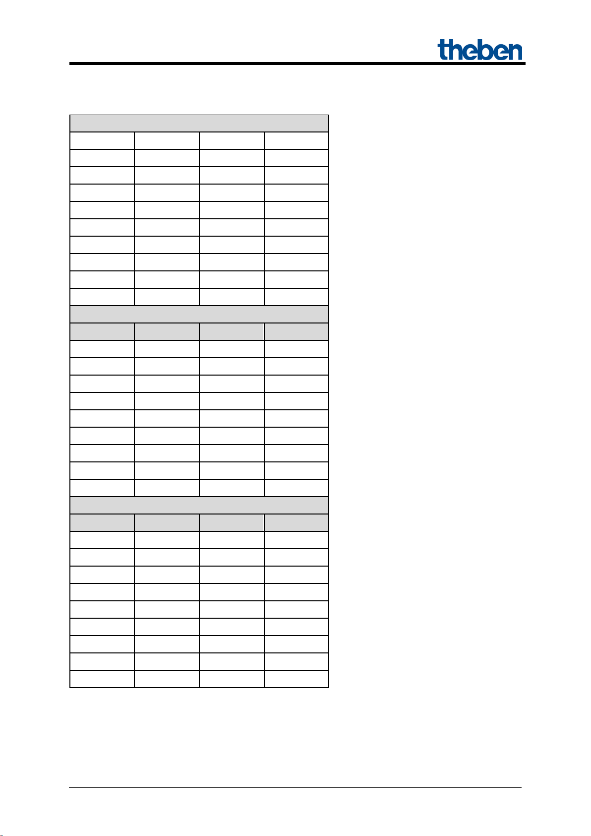
7.1.2 Call up or save scenes:
To call up or save a scene, the relevant code is sent to the scene object (obj. 243).
Table 31
Scene
Updated: Apr-15 (Subject to changes) Page 48 of 50
Page 49

MIX 2 series RMG 4 U / RME 4 U actuators
Call up
Save
Hex
Dec.
Hex
Dec.
33
$20
32
$A0
160
34
$21
33
$A1
161
35
$22
34
$A2
162
36
$23
35
$A3
163
37
$24
36
$A4
164
38
$25
37
$A5
165
39
$26
38
$A6
166
40
$27
39
$A7
167
41
$28
40
$A8
168
42
$29
41
$A9
169
43
$2A
42
$AA
170
44
$2B
43
$AB
171
45
$2C
44
$AC
172
46
$2D
45
$AD
173
47
$2E
46
$AE
174
48
$2F
47
$AF
175
49
$30
48
$B0
176
50
$31
49
$B1
177
51
$32
50
$B2
178
52
$33
51
$B3
179
53
$34
52
$B4
180
54
$35
53
$B5
181
55
$36
54
$B6
182
56
$37
55
$B7
183
57
$38
56
$B8
184
58
$39
57
$B9
185
59
$3A
58
$BA
186
60
$3B
59
$BB
187
61
$3C
60
$BC
188
62
$3D
61
$BD
189
63
$3E
62
$BE
190
64
$3F
63
$BF
191
Continuation:
Scene
Examples (central or channel-related):
Calling status of scene 5:
→ Send $04 to the relevant scene object.
Save current status with scene 5:
→ Send $84 to the relevant scene object.
Updated: Apr-15 (Subject to changes) Page 49 of 50
Page 50

MIX 2 series RMG 4 U / RME 4 U actuators
Percentage
value
Hexadecimal
00
1a
33
4D
66
80
99
B3
CC
E6
FF
Decimal
00
26
51
77
102
128
153
179
204
230
255
7.1.3 Teach in scenes without telegrams (MIX2 devices ONLY)
Instead of defining scenes individually by telegram, this can be done in advance in the ETS.
This merely requires the setting of the A ll chann el scen e status es (Sce nes p ar ameter page) to
Overwrite at download.
Accordingly, the required status can be selected for each of the 8 possible scene numbers in a channel
(= Status after download parameter).
The scenes are programmed into the device after the download has been completed.
Later changes via teach in telegrams are possible if required and they can be permitted or blocked via
a parameter.
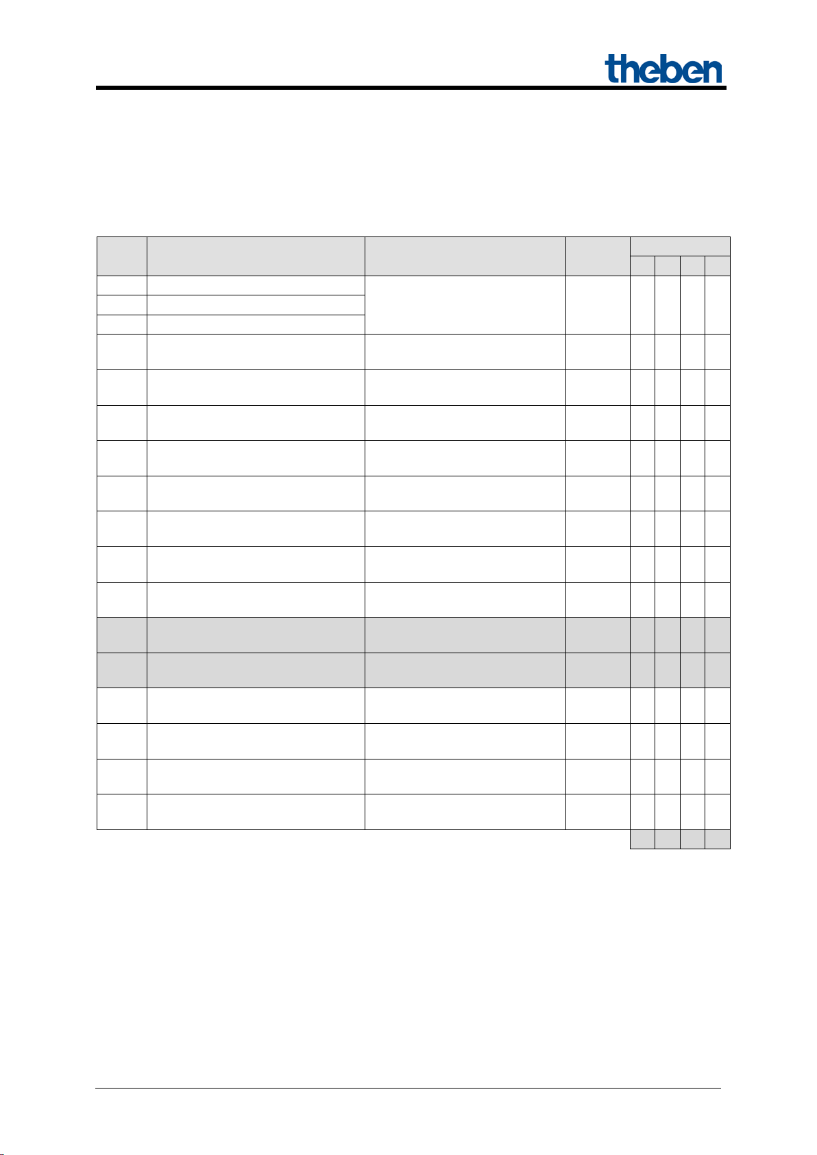
7.2 Conversion of percentages to hexadecimal and decimal values
0% 10% 20% 30% 40% 50% 60% 70% 80% 90% 100%
All values from 00 to FF hex. (0 to 255 dec.) are valid.
Updated: Apr-15 (Subject to changes) Page 50 of 50
 Loading...