

Page 1
The heating actuator of type HMG 8 is suitable for use with the European
Installation bus- in connection with the t-product database.It is
fitted with the BCU 2 for the bus communication.
Basic device HMG 8
• 8 heating outputs,each capable of handling up to 10 thermal actuators
Expansion units
• HME 8 8 additional heating outputs
• HMx 4 4 additional heating outputs
• RME 8 8 switching outputs
• RMX 4 4 switching outputs
• FME 8 8 window contact inputs with safety extra low voltage (SELV)
1.0 Use in accordance with the intended application
Both routing and connecting up the bus cable as well as installation work must be
carried out in accordance with the applicable regulations and guidelines of DINVDE, as well as with the EIB Handbook from ZVEI/ZVEH.The work may only be
carried out by qualified electricians with appropriate EIB training. National norms
and the applicable safety regulations shall be observed.Any changes made to the
device will invalidate the guarantee.
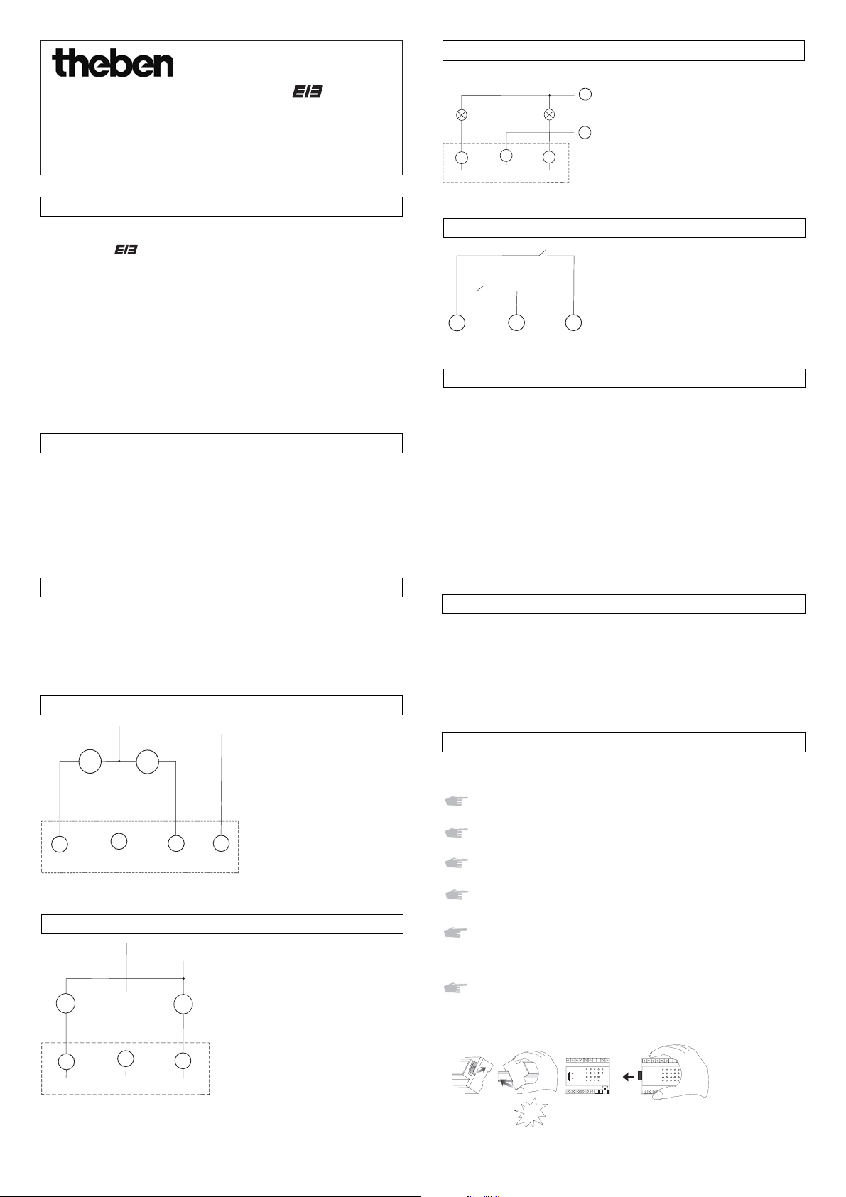
2.0 Electrical connection
2.2 Thermal actuators HMG 8, HME 8
2.4 Switching outputs RME 8, RMX 4
2.1 Network connection
The heating module HMG 8 can be expanded by using max. 1 expansion module.
No new EIB programming is required when replacing a defective device.
Remove the strip of insulation of the right-hand side of the HMG 8
device (fig.1).
Keep the strip of insulation for further use by attaching underneath the
opening for the plug-in contact.
Snap the modules HMG 8 and the expansion module onto the multiterminal rail (fig.2).
Push the module HMG 8 and the expansion module completely
together (fig. 3).
Connection
Connect up the switch actuator in accordance with the circuit diagram
shown in chapter 2.2.
Removal instructions
When moving the expansion module,always protect the opening of the
remaining actuator HMG 8 by covering with a strip of insulating tape!
2.6 Bus connection
4.0 Expansion modules
310 498
Behaviour without ETS programming
The connected expansion modules are detected and actuated.
• HME 8 and HMX 4
- Actuator behavior:when switched on,it is in heating mode.
- The output value is 50 %.
- Can be manually operated for testing purposes.
• RME 8 and RMX 4
- Relays stays off.
- Can be manually operated (manual ON/OFF)
• FME 8
- LED status display
• see also section 6.0
3.0 Behaviour during a power or an operational failure
Note concerning power failure
All relays - irrespective of their assigned parameters - drop during a power failure.
This means that the electric circuit is opened.
Note concerning a bus failure only
Provided power is still being supplied the relays can be switched from the device´s
keypad in the event the bus fails.
Operating Instructions for Heating Actuator
-
Heating actuator HMG 8 and expansion units
Heating modules HME 8 and HMX 4
Switching modules RME 8 and RMX 4
Window contact module FME 8
Each module must be connected to a standard main power source.
Connecting the expansion module
Be sure to use the same phase and fused circuit as used for the base module
supply voltage to the logic system (L-, N connections).
• Uin is for a commun voltage supply
to the actuators (230 V~,same
phase as for the actuators).
• It is galvanically isolated from the
standard main power source so that
24 V~ thermal actuators can also
be used.
Please note:
• Switching differently -phased external
conductors in one device is generally
allowed.
refer to the product manual for:
=> Using contactors or relays when
actuating in order to achieve
higher switching capacities
=> Switching of savety extra low
voltage
2.5 Window contacts FME 8
•The COM ports provide an SELV
for the window contacts.
•All COM ports are internally
connected to each other.
e.g.channel 1
Lighting connection
2.3 Thermal actuator HMX 4
• Uin 1 and Uin 2 are galvanically
isolated from each other and the
standard mains power source so
that 24 V~ thermal actuators can
also be used.
e.g.channel 1
Uin
24-250 V AC/DC
24-250 V AC/DC
1
2
3
N
L
2
COM
3
4
E2E1
M
~J
4
M
~J
5
67
M
J
1
2
M
J
3
1.
2.
JMG 4 RME 8
Klick
3.
Page 2
8.0 Technical data
The device is appropriate for use under the conditions of usual contamination.Also
observe any technical information on the device ´s nameplate deviating from this!
Subject to terminal improvements.The devices meet the requirements of the European Directives 73/23/EWG (Low-voltage Directive) and 89/336/EWG (Directive).
Ensure when using these devices togehter with other devices in one system that
there is no radio interference caused by the whole system.
6.0 Manual operation
7.0 Commissioning
Manual operation of HMG 8
• After a channel button is pressed,its relay is switched on for 2 actuation cycles
(two PWM periods).With the parameter setting "Actuator behavior:no heating
after switch on" the relay is switched off so that the valve is opened.Pressing
the channel button once again ends the manual mode.
• Pressing the position button at the same time as a channel button displays the
status of the channel (controlled value - output value) on the LEDs for channels
H1 to H4 as a % value in the following steps: 0 %, >0 %, >25 %, >50 %, >75 %.
HMG 8 HME 8, HMX 4 RME 8/ RMX 4 FME 8
Operating voltage 230 V/240 V ±10 %
Rated frequency 50 Hz
Power consumption approx. 4 VA
EIB current cons. 8 mA ---- ---- ----
Contact-making mat.
AgSnO
Contact type potential-free make contact element ---Switching capacity
cos = 1 2 A (250 V~) 2 A (250 V~) 10 A (250 V~) ---cos = 0,6 ---- ---- 6 A (250 V~) ----
Incandescent lamp cap.
---- ---- 1400 W ----
Halogen lamp cap. ---- ---- 1400 W ----
Terminal dimensions heavy duty,0.5 mm2(0.8 diameter) to 4 mm
2
(cross section) flexible lead with ferrule,0.5 mm2bis 2.5 mm
2
Permissible ambient
temperature -5 °C ... +45 °C (-5T45)
Protection class Il following proper installation
Protection type IP 20 meeting EN 60529
Device standard EN 60730
Appliance 45 x 105 x 60 mm (6 TE) + (HME 4,RMX 4 3TE)
Window contact ---- ---- ---- 20 V/ 2mA
load typical
---- ---- ---- max. cable
length: 200 m
Refer to the handbook for more detailed switching capacity information for other
types of lighting
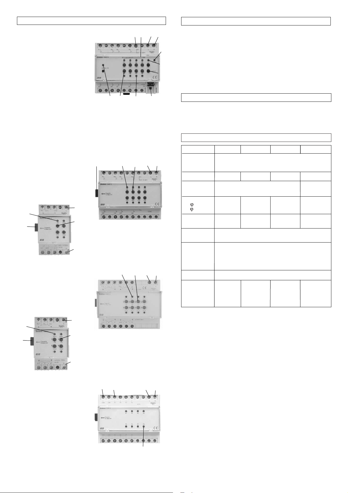
Basic device HMG 8
1 a common power supply for
thermal actuators
2 Output status display for each
channel (% value)
3 Power LED
(blinks,if no bus communication
or programmed expansion device,
refer to handbook
4 Summer mode ON/OFF
5 Position button
(see also section 6.0)
6 Bus connection
7 Current relay status ON/OFF
(blinks during manual, forced or
emergency operation)
8 Channel button
9 Set Phys Adr programming key
and LED for physical address
Expansion modules HME 8, HMX 4
10 Interface between expansion
module and the basic device
11 LED ON = contact
(like basic device)
12 Keys (like basic device)
5.0 Description
The ETS-database can be found www.theben.de/downloadseite.htm#g.
Please refer to the handbook for more detailed description of these functions (e.g.
lights,priority sequence,etc.).
<
6
5
8
9
7
3
4
2
L
N
1
10
11
12
L
N
13
14
10
L
N
11
12
L
N
11
L
N
15
Window contact module FME 8
13 COM = output voltage (all COM
ports are internally linked)
14 Inputs
15 LED status displays
If you use the window contact module
FME 8 with JMG 4 DC, see operating
instructions for JMG 4 DC.
10
12
Expansion modules RME 8, RMX 4
10 Interface between expansion
module and the basic device
11 LED ON = contact
(like basic device)
12 Keys (like basic device)
11
12
L
N
Theben AG
Hohenbergstr.32
72401 Haigerloch
Tel. +49 (0) 74 74/6 92-0
Fax +49 (0) 74 74/6 92-150
Service
Tel. +49 (0) 90 01 84 32 36
Fax +49 (0) 74 74/6 92-207
hotline@theben.de
Adresses, telephone numbers etc. at
www.theben.de
 Loading...