

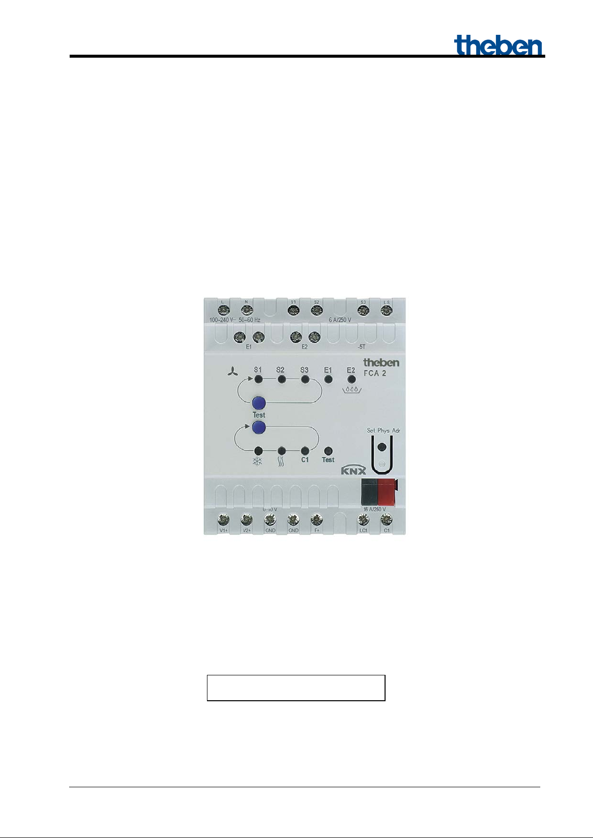
Fan Coil Actuator FCA 2
FCA 2 4920210
Fan Coil Actuator FCA 2
Updated: Feb-16 (subject to changes) Page 1 of 89

Fan Coil Actuator FCA 2
Contents
1 Function description ................................................................................................................. 4
1.1 Operation and display ....................................................................................................... 5
1.2 Advantages of the FCA 2 ................................................................................................. 6
1.2.1 Special features ............................................................................................................ 6
2 Technical Data ......................................................................................................................... 7
3 The application program "FCA 2 Fan Coil Actuator 0-10V" .................................................. 8
3.1 Selection in the product database ..................................................................................... 8
3.2 Parameter pages ................................................................................................................ 9
3.3 Communication objects .................................................................................................. 10
3.3.1 Characteristics of objects ........................................................................................... 10
3.3.2 Description of objects ................................................................................................. 13
3.4 Parameters ...................................................................................................................... 25
3.4.1 Parameter page General ............................................................................................. 25
3.4.2 Parameter page Fan .................................................................................................... 27
3.4.3 Parameter page Heating valve .................................................................................... 33
3.4.4 Parameter page Cooling valve .................................................................................... 35
3.4.5 Parameter page "Heating/cooling valve" (only with 2-pipe system) ......................... 36
3.4.6 Parameter page Additional relay ................................................................................ 37
3.4.7 Parameter page E1 ...................................................................................................... 38
3.4.8 Parameter page E2 ...................................................................................................... 39
3.4.9 Parameter page Condensation monitoring ................................................................. 39
3.4.10 Parameter page Setpoint adjustment ...................................................................... 40
3.4.11 Parameter page Setpoints (internal controller) ....................................................... 42
3.4.12 Parameter page Regulation (internal controller) .................................................... 44
3.4.13 Parameter page Operating mode and operation (internal controller) .................... 48
3.4.14 Parameter page Filter monitoring .......................................................................... 50
3.4.15 Parameter page Actuating value loss ...................................................................... 51
4 Start-up ................................................................................................................................... 52
4.1 Test mode ....................................................................................................................... 52
4.2 Device LEDs in automatic mode ................................................................................... 56
5 Typical applications ............................................................................................................... 57
5.1 Base configuration (4-pipe system): Heating and cooling with fan coil with external
controller .................................................................................................................................... 57
5.1.1 Devices: ...................................................................................................................... 57
5.1.2 Overview .................................................................................................................... 57
5.1.3 Objects and links ........................................................................................................ 57
5.1.4 Important parameter settings ...................................................................................... 58
5.2 Base configuration (2-pipe system): Heating and cooling with fan coil with external
controller .................................................................................................................................... 59
5.2.1 Devices: ...................................................................................................................... 59
5.2.2 Overview .................................................................................................................... 59
5.2.3 Objects and links ........................................................................................................ 59
5.2.4 Important parameter settings ...................................................................................... 60
5.3 4-pipe system: Heating and cooling with fan coil, external controller and dew point
alarm 61
5.3.1 Devices ....................................................................................................................... 61
5.3.2 Overview .................................................................................................................... 61
5.3.3 Objects and links ........................................................................................................ 62
Updated: Feb-16 (subject to changes) Page 2 of 89

Fan Coil Actuator FCA 2
5.3.4 Important parameter settings ...................................................................................... 63
5.4 Typical application (4-pipe system): .............................................................................. 64
5.4.1 Task: ........................................................................................................................... 64
5.4.2 Devices: ...................................................................................................................... 64
5.4.3 Overview .................................................................................................................... 64
5.4.4 Implementation: ......................................................................................................... 65
Objects and links .................................................................................................................... 66
5.4.5 Important parameter settings ...................................................................................... 67
6 Appendix ................................................................................................................................ 69
6.1 Monitoring of actuating value ........................................................................................ 69
6.1.1 Application ................................................................................................................. 69
6.1.2 Principle ..................................................................................................................... 69
6.1.3 In practice ................................................................................................................... 69
6.2 Setting the valve characteristic ....................................................................................... 70
6.3 Setpoint offset ................................................................................................................ 71
6.4 Setpoint adjustment ........................................................................................................ 71
6.4.1 Use with internal controller ........................................................................................ 71
6.4.2 Use with external controller ....................................................................................... 71
6.4.3 Format of setpoint correction: Relative ...................................................................... 72
6.4.4 Format of setpoint correction: Absolute ..................................................................... 74
6.5 Frost protection (or heat protection) via window contact .............................................. 76
6.5.1 with external controller .............................................................................................. 76
6.5.2 with internal controller ............................................................................................... 76
6.6 Dead zone ....................................................................................................................... 76
6.7 Determining the current operating mode ....................................................................... 77
6.7.1 New operating modes ................................................................................................. 77
6.7.2 Old operating modes .................................................................................................. 78
6.7.3 Determination of the setpoint ..................................................................................... 79
6.7.4 Heating and cooling in the 2-pipe system .................................................................. 81
6.7.5 Heating and cooling in the 4-pipe system .................................................................. 81
6.8 Fan control ...................................................................................................................... 82
6.8.1 Priorities ..................................................................................................................... 82
6.8.2 Fan forced mode with RAM 713 Fan Coil ................................................................. 83
6.8.3 Time between heating and cooling and overrun phase .............................................. 85
6.8.4 Hysteresis ................................................................................................................... 86
6.9 Temperature control ....................................................................................................... 87
6.9.1 Introduction ................................................................................................................ 87
6.9.2 Response of the P controller ....................................................................................... 88
6.9.3 Response of the PI controller ..................................................................................... 89
Updated: Feb-16 (subject to changes) Page 3 of 89

Fan Coil Actuator FCA 2
1 Function description
• Fan coil actuator
• For controlling fan coils
• For 2- and 4-pipe systems
• For up to three fan stages
• Fans optionally also with 0-10 V output
• For proportional valves 0-10 V
• Additional relay for electrical heater or cooler bank
• Floating input for window contacts or temperature sensor
• Floating input condensation monitoring
• Display of operation status via 9 LEDs
• Manual operation on device (fan stages, switching between heating and cooling)
• Adjustment of setpoint for cooling in relation to external temperature
• Floating switching contact for either cooler or heater bank
• With emergency program
Updated: Feb-16 (subject to changes) Page 4 of 89
Fan Coil Actuator FCA 2
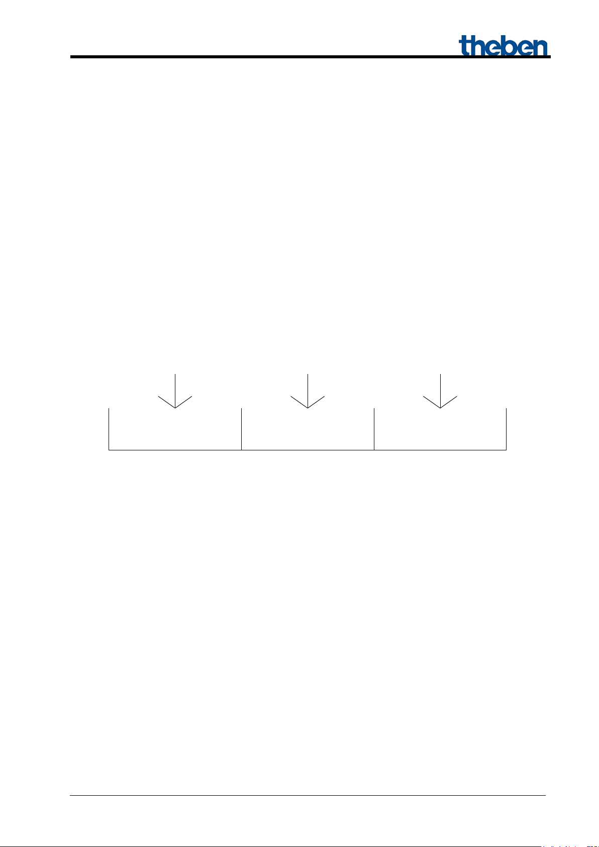
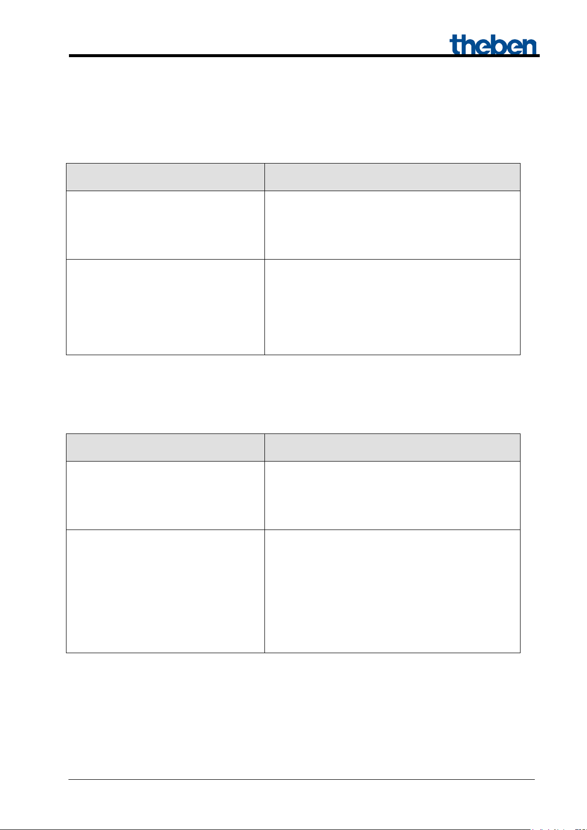
S1
S2
S3
Fan stages (standard fan, 1-3 stages)
1-32 %
33-65 %
66-100 %
Fan speed (0-10 V control)
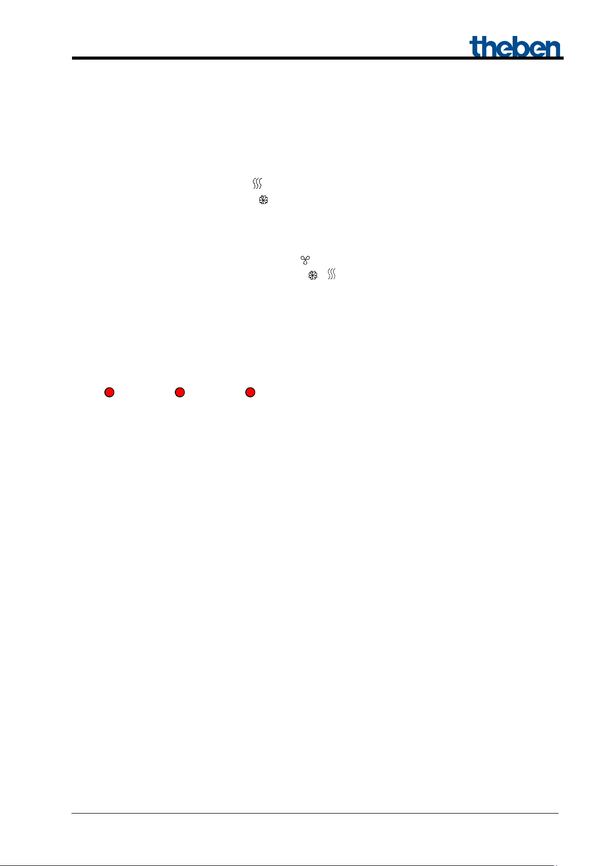
1.1 Operation and display
FCA 2 is fitted with 9 LEDs and 2 push buttons.
• 3 red LEDs for displaying fan stage/fan speed (see figure 1)
• 1 red LED for heating mode
• 1 blue LED for cooling mode
• 1 red LED for the additional relay (C1)
• 2 red LEDs for inputs 1 and 2 (E1, E2)
• 1 red LED for test mode
• 1 push button for fan stages/fan speed
• 1 push button for heating/cooling mode /
Figure 1: LEDs for displaying fan stages or fan speed
By using the manual button, the fan stages can be switched one after another.
• Standard fan control: Off stage 1 stage 2 stage 3 Off stage 1 etc.
• 0-10 V fan control: Off 33% 66% 100% Off 33% etc.
Updated: Feb-16 (subject to changes) Page 5 of 89

Fan Coil Actuator FCA 2
1.2 Advant a ge s of t he FCA 2
• Operating voltage 100-240 V 50/60 Hz.
• Suitable for 0-10 V valves.
• Optional internal or external temperature controller.
• Can be used in 2- and 4-pipe systems.
• Also suitable for 0-10 V fans.
• Easy start-up via 2 push buttons for fan and heating/cooling mode.
• Additional relay for heating/cooling can also be used as a switch output.
• Change of operating mode by means of presence and window objects.
• Adjustable direction of action of inputs.
• Heating/cooling object addressable as per DPT 1.100 or inverted.
1.2.1 Special features
• Control via external actuating value or with integrated room thermostat.
• Additional relay C1 can also be controlled as switching actuator channel via the bus
• Setpoint in cooling mode can be adjusted in relation to the outdoor temperature
• E1 and E2 can be used as binary inputs if required.
Updated: Feb-16 (subject to changes) Page 6 of 89
Fan Coil Actuator FCA 2
Power supply via mains
230 +/-10 VAC 50 Hz
Operating voltage KNX
Bus voltage, ≤ 8 mA
Operating voltage
100 – 240 V AC
Frequency
50 – 60 Hz
Width
4 TE
Type of installation
DIN-rail
Type of contact
NO contact
Switching capacity, additional relay
16 A
Switching capacity, ventilator relay
6 A
Ambient temperature
-5 °C … +45 °C
Protection rating
IP 20
Protection class
II in accordance with EN 60 730-1
2 Technical Data
Updated: Feb-16 (subject to changes) Page 7 of 89
Fan Coil Actuator FCA 2
Manufacturer
Theben AG
Product family
Heating, ventilation, air conditioning
Product type
Fan coil actuators
Program name
FCA 2 Fan Coil Actuator 0-10V
Number of communication objects
33
Number of group addresses
64
Number of associations
64
3 The application program "FCA 2 Fan Coil
Actuator 0-10V"
3.1 Selection in the product database
The ETS database can be found on our website: www.theben.de/en/downloads_en
Table 1
Updated: Feb-16 (subject to changes) Page 8 of 89
Fan Coil Actuator FCA 2
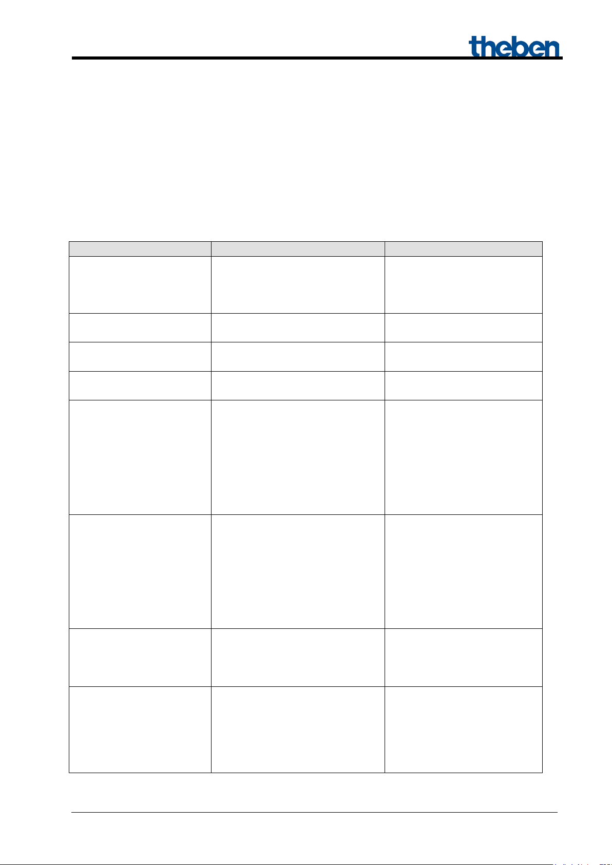
Function
Description
General
Supported functions, operation, filter change
Fan
Number of fan stages, switch-on thresholds, etc.
Heating valve
Factory settings for heating valve
Cooling valve
Factory settings for cooling valve
Heating/cooling valve
Factory valve settings for 2-pipe systems
Additional relay
Use of additional relay C1
E1.. E2
Settings for inputs E1 and E2
Condensation monitoring
Reaction to condensate and signal source
Setpoint adjustment
Setpoint offset dependent on outdoor temperature
Setpoints
Setpoint after download, values for night, frost mode etc.
Control
Control parameter settings for the internal temperature controller
Operating mode and operation
Factory settings for changing operating modes
Filter monitoring
Basic settings for filter change
Actuating value loss
Monitoring of the actuating value with external controller
3.2 Parameter pages
Table 2
Updated: Feb-16 (subject to changes) Page 9 of 89
Fan Coil Actuator FCA 2
Type
DPT
Heating actuating value
Receive
C R W
-
Heating/cooling actuating
value
Actuating value for fan
Receive
C R W - Cooling actuating value
Receive
C R W
-
Heating/cooling actuating
value
Heating actuating value
Send
C R - T Cooling actuating value
Send
C R -
T
1 bit
1,003
1 bit
1,001
1 byte
5,001
1 bit
1,001
1 bit
1,100
1 byte
5,001
1 bit
1,001
1 bit
1,001
1 byte
5,010
1 byte
5,001
1 bit
1,001
1 bit
1,001
1 bit
1,001
1 bit
1,001
3.3 Communication objects
3.3.1 Characteristics of objects
FCA2 features 33 communication objects.
Some objects can assume various functions, depending on their configuration.
Table 3
No. Function Object name
Receive C R W -
0
Send C R - T
Enable cooling 1 = Enable cooling
Disable heating 1 = Heating disabled
Cooling actuating value Receive
1
Heating / cooling Heating = 0, Cooling = 1
Heating / cooling Heating = 1, Cooling = 0
C R W T
1 byte
5,001
C R W -
C R W -
C R W -
C R W -
C R W -
Cooling actuating value Send
2 Heating status Report
3 Cooling status Report
Fan stage Report
C R - T
C R - T
C R - T
C R - T
4
Fan speed Report
Additional relay status Report
C R - T
C R - T
5
Additional relay Switching
6 Block additional ventilation 1 = Block
7 Fan block 1 = Block
Updated: Feb-16 (subject to changes) Page 10 of 89
C R W -
C R W -
C R W -
Fan Coil Actuator FCA 2
No.
Function
Object name
Type
C R W
T
Fan stage in forced
operation
1 byte
5,001
Fan stage in forced
operation
1 byte
5,010
1 byte
5,001
0=Fan OFF
1..100%=max.stage
1 byte
5,001
Limitation of fan stage (1-2-
3)
0=Fan OFF
1-3=max.stage
1 byte
5,010
1 bit
1,001
1 bit
1,001
1 bit
1,001
1 bit
1,001
Status of window contact at
E1
1 bit
1,019
2 byte
9,001
Receive: Auto = 1, Forced =
0
Receive: Forced = 1, Auto =
0
Status of condensation
monitoring
Status of condensation
monitoring
Status of window contact at
E2
1 bit
1,019
1 bit
1,001
2 byte
9,001
2 byte
9,002
2 byte
9,001
Actuating value loss
1 = Actuating value loss
1 bit
1,001
Sensor failure
Sensor failure
Continuation:
Fan control with % value
8
Fan control via level
Limitation of fan stage in % 0=Fan OFF 1..100%=max.
9
Limitation of fan stage in %
10 Fan off Report
11 Fan stage 1 Report
12 Fan stage 2 Report
13 Fan stage 3 Report
Report
14
Actual value at E1 Report
C R W -
C R W -
C R W -
C R W -
C R W -
C R - T
C R - T
C R - T
C R - T
C R - T
C R - T
Fan auto/forced mode
15
Fan Forced/Auto
Input
16
Report C R - T
Report
17 Dew point alarm Input
18 Outdoor temperature Input
Adjust setpoint Delta in K
19
Adjust setpoint Value in °C
20
1 bit
1,001
1 bit
1,001
C R W -
C R W -
C R - T
C R W -
C R W -
C R - T
C R - T
C R - T
Updated: Feb-16 (subject to changes) Page 11 of 89

Fan Coil Actuator FCA 2
No.
Function
Object name
Type
C R W
T
1 bit
1,001
1 byte
20,102
1 bit
1,001
1 bit
1,018
1 bit
1,001
1 bit
1,019
1 byte
20,102
2 byte
9,002
2 byte
9,001
2 byte
9,001
1 bit
1,001
1 bit
1,100
No energy medium
1 = Wrong energy medium
Heating mode, but heating
blocked
Cooling mode, but cooling
blocked
Fan duty time since last filter
change
2 byte
7,007
1 bit
1,001
1 bit
1,003
Flags
Name
Meaning
C
Communication
Object can communicate
R
Read
Object status can be queried
W
Write
Object can receive
T
Transmit
Object can send
Continuation:
Night mode <-> Standby 1 = Night mode
21
Operating mode preset Operating mode preset
Comfort 1 = Comfort mode
22
Presence Input for presence signal
Frost protection 1 = Frost protection
23
Window Input for window contact
24 Current operating mode Send
25 Manual offset Receive
26 Base setpoint Receive
27 Current setpoint Send
Heating / cooling Heating = 0, Cooling = 1
28
Heating / cooling Heating = 1, Cooling = 0
C R W -
C R W -
C R W -
C R W -
C R W -
C R W -
C R - T
C R W -
C R W -
C R - T
C R W -
C R W -
29
1 = Heating blocked
1 = Cooling blocked
30
Time in hours
31 Change filter* 1 = Change, 0 = Reset
32 Activate test mode Report
* Also serves as reset input for filter change status.
Key
1 bit
1,001
C R - T
C R - T
C R W T
C R - T
Updated: Feb-16 (subject to changes) Page 12 of 89

Fan Coil Actuator FCA 2
Heating
Transmits the current
valve
Receives the actuating
4-pipe system or
system
Cooling
Transmits the current
valve
Receives the actuating
cooling only
Heating and
Transmits the current
cooling valve
Receives the actuating
2-pipe system
Fan
receives the actuating value for fan control
Ventilation
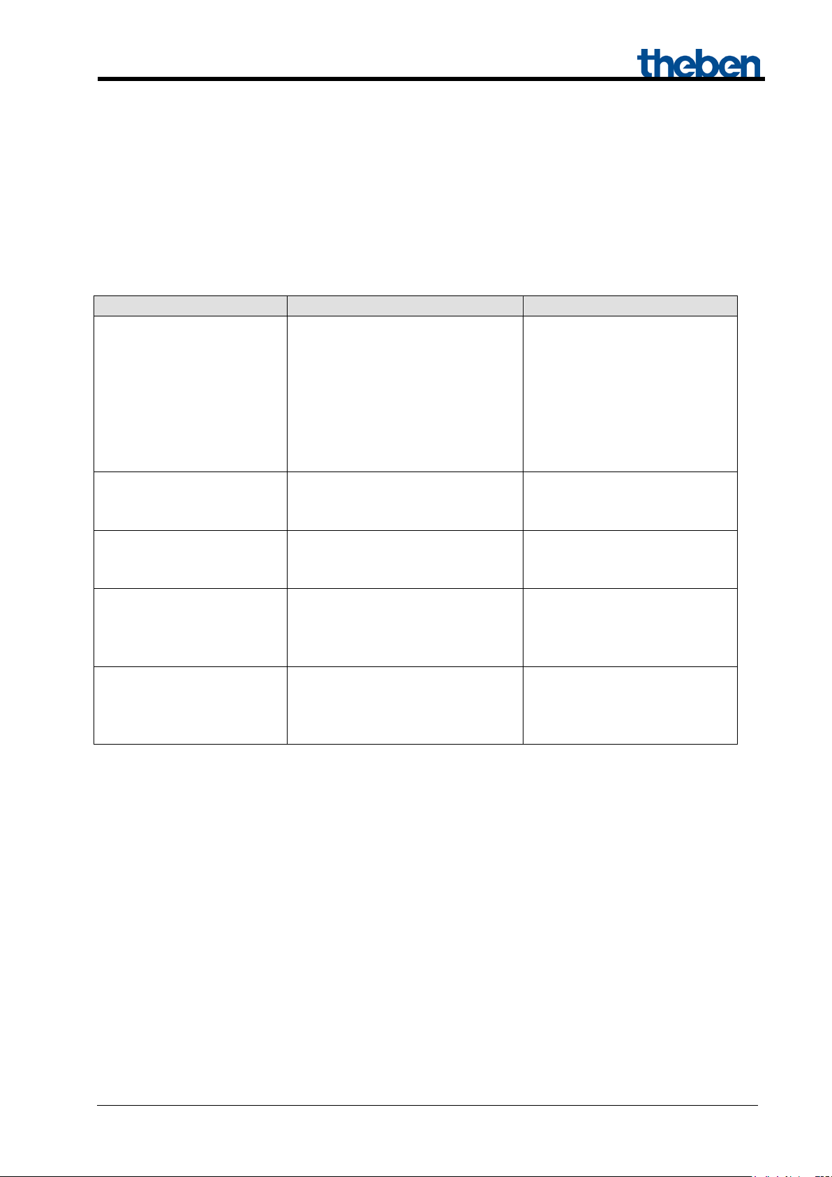
3.3.2 Description of objects
• Object 0 "Actuating value for fan" / "Actuating value heating/cooling" transmit or
receive.
The function of the object is connected with the parameters "Supported function" and
"Type of controller used" on the "General" parameter page.
Table 4.
Supported
function
cooling
Kind of controller used and Function of object
internal controller external controller
actuating value of heating
actuating value of cooling
actuating value of the
common heating and
value for the heating valve
value for the cooling valve
value for the common
heating and cooling valve
Installation type
heating only
system
Updated: Feb-16 (subject to changes) Page 13 of 89

Fan Coil Actuator FCA 2
Heating and
Change over between
DPT 100
Inverted
Heating = 1
Heating = 0
Cooling= 0
Cooling= 1
With external controller: Receive
Heating
Block heating:
After reset, object value = 0, i.e. heating permitted
Cooling
Enable cooling:
After reset, object value = 1, i.e. cooling permitted
• Object 1 "Actuating value cooling", "Heating/cooling", "Block heating", "Enable
cooling"
The function of the object is connected with the parameters "Supported function" and
"System type" on the "General" parameter page.
Table 5
Supported
function
cooling
2-pipe system 4-pipe system
heating and cooling mode.
The direction of action is defined by
parameter Format object
Installation type
cooling actuating value.
With internal controller: Send
cooling actuating value.
heating/cooling
(see General parameter page).
1 on this object blocks the heating function.
The block can be cleared with a 0.
1 on this object permits cooling function.
0 on this object blocks the cooling function.
• Object 2 "heating status"
Sends the current heating status:
1 = Actuating value heating is greater than 0 %, heating is switched on.
0 = Actuating value heating is 0 %, heating is currently switched off
• Object 3 "Cooling status"
Sends the current cooling status:
1 = Actuating value cooling is greater than 0 %, cooling is switched on.
0 = Actuating value cooling is 0 %, cooling is currently switched off
Updated: Feb-16 (subject to changes) Page 14 of 89

Fan Coil Actuator FCA 2
Standard (1-3 stages)
0-10 V
2 formats can be selected:
object
The fan speed is sent as a percentage
• Object 4 „fan stage“, „fan speed“
Reports the current fan stage or fan speed.
Depending on the configured fan controller (General parameter page), the object either sends the
current stage (0..3) or the speed in percent.
Table 6: Fan controller.
- 1 byte number between 0 and 3.
value.
- Percentage value
See parameter Format and cycle time fan stage
• Object 5 "Additional relay", "additional relay status"
The function of this object is dependent on the "Switching on additional relay" parameter on the
"Additional relay" parameter page.
Using the "via object setting, the additional relay can be controlled externally via the bus with
object 5.
With all other settings, object 5 reports the current status of the additional relay.
• Object 6 "Blocking additional ventilation"
Block object for the "additional ventilation" function if it is activated.
1 = Block
0 = Cancel block
• Object 7 "Fan block"
Block object for fan control.
1 = Block fan (fan off)
0 = Automatic operation
Updated: Feb-16 (subject to changes) Page 15 of 89
Fan Coil Actuator FCA 2
Forced-operation telegram
Forced-operation telegram
Forced-operation telegram
25 %
55 %
85 %
STAGE 1
STAGE 2
STAGE 3
10 %
40 %
70 %
100 %
Switch-on thresholds
• Object 8 "Fan stage in forced operation"
Via this object, the desired fan stage in forced operation is either defined as a percentage value
between 0 % and 100 % or as a stage (1-3).
See parameter Format of forced operation and limitation on Fan parameter page.
With 0-10 V fan control, only the percentage value format is permitted.
The specification fan stage can either be made with the button at the room thermostat
RAM 713 FC or via a KNX sensor (e.g. push button), which is configured for this purpose.
Forced operation is activated by Object 15.
Example of percentage value:
Recommended forced telegrams for the following settings on the "Fan" parameter page:
Switch-on threshold for fan stage 1 = 10 %
Switch-on threshold for fan stage 2 = 40 %
Switch-on threshold for fan stage 3 = 70 %
Figure 2
Updated: Feb-16 (subject to changes) Page 16 of 89
Fan Coil Actuator FCA 2
Value
Highest permissible fan stage
0 %
The fan is not switched on
1 % .. 99 %
Maximum permissible fan speed for normal and forced operation
100 %
No limit, automatic operation (= object value after reset)
Received value on object 9
Maximum fan stage
0 % .. 9 % 2
The fan is not switched on
10 % .. 39 %
1
40 % .. 69 %
2
70 % .. 100 % 3
3
Received value on object 9
Maximum fan speed
0 % .. 9 % 2
The fan is not switched on
10 % .. 99 %
Value from object 9
• Object 9 "Limitation of fan stage in %", "Limitation of fan stage (1-2-3)"
This object can be used to set the maximum permitted actuating value and the associated
maximum fan stage, either as a percentage value or as stage (1-3).
1
With 0-10 V fan control, only the percentage value format is permitted.
The following values are used.
Table 7
Example of percentage value:
Configured switch-on thresholds:
Fan stage 1, or switch-on threshold (at 0-10 V) = 10 %
Fan stage 2 = 40 % (only with standard)
Fan stage 3 = 70 % (only with standard)
Table 8: Standard f an controller.
Table 9: 0-10 V Fan controller.
• Object 10 "Fan off“
Report object for the fan status.
Sends a 1 if the fan is switched off.
1
See parameter Format of forced operation and limitation on Fan parameter page.
2
The value is under the switch-on threshold for stage 1, the fan cannot be switched on.
3
The value is greater/equal to the switch-on threshold for stage 3, i.e. no limitation.
Updated: Feb-16 (subject to changes) Page 17 of 89
Fan Coil Actuator FCA 2
Parameters
"Function of E1"
Meaning
E1 = Window contact
Sends the current status of the window contact to the bus.
→ Only available when using an external controller.
E1 = Actual value
sensor
Sends the currently measured room temperature to the bus.
→ Fixed setting when using an internal controller.
• Object 11 "Fan stage 1"
Only available if fan controller = standard.
Report object for the fan status.
Sends a 1 if the fan is switched to stage 1.
• Object 12 "Fan stage 2"
Only available if fan controller = standard.
Report object for the fan status.
Sends a 1 if the fan is switched to stage 2.
• Object 13 "Fan stage 3"
Only available if fan controller = standard.
Report object for the fan status.
Sends a 1 if the fan is switched to stage 3.
• Object 14 "Actual value at E1", "Window contact status at E1"
The object function depends on the "Function of E1" parameter on the "E1" parameter page.
Table 10
• Object 15 "Fan forced/ auto", "fan auto/forced"
This object is used to activate or leave the forced operation of the fan.
The desired fan stage or speed for forced operation is set by Object 8.
The direction of action of the forced object is adjustable on the General parameter page.
The forced operation of the fan has no effect on valve control.
Updated: Feb-16 (subject to changes) Page 18 of 89
Fan Coil Actuator FCA 2
Parameters
monitoring“
E2
Sends the status of the condensation monitoring
Receives the status of the condensation monitoring
from the bus
Format of
value
Function
Example
Absolute
Sends the amount:
controllers.
Unadjusted base setpoint = 20 ºC.
Relative
Calculated setpoint correction (in
temperature.
Unadjusted base setpoint = 20 ºC.
The object sends: 2 K*
• Object 16 "Condensation monitoring status"
The function of this object depends on the "Source for drip condensation monitoring" parameter
on the "Condensation monitoring" page.
Table 11
„Source for condensation
Function
Object 16
• Object 17 "Dew point alarm“
Receives the dew point alarm telegrams.
1 = Alarm
Note: The behaviour is identical with the behaviour set for condensation monitoring.
• Object 18 "Outside temperature"
Receives the outdoor temperature for setpoint adjustment
• Object 19 "Adjust setpoint"
Reports the current setpoint correction as an amount or as a differential.
The format of the correction value is set on the setpoint adjustment parameter page.
Table 12
correction
Unadjusted base setpoint
+ setpoint correction as setpoint
for additional temperature
Kelvin) based on outside
Setpoint correction = +2 K
The object sends: 22 ºC*
Setpoint correction = +2 K
*Important: If the Use setpoint adjustment for regulation parameter is set on "yes", the base
setpoint after reset (i.e. setpoint for the internal controller) is also adjusted.
In our example it is raised by 2 K in both cases.
Updated: Feb-16 (subject to changes) Page 19 of 89
Fan Coil Actuator FCA 2
„Type of controller used“
Function
Reports error if the temperature sensor connection is
interrupted or shorted.
Reports whether the actuating value is being received
0 = Actuating value OK
"Objects for determining the operating
mode"
Function
new: operating mode, presence, window
1 byte object.
The details in brackets refer to cooling mode.
old: comfort, night, frost
With this setting, the object is a 1 bit object. It can
0=Standby 1=Night
• Object 20 "Actuating value loss" / "sensor failure"
The function of the object depends on the "Type of controller used" parameter on the "General"
parameter page.
Table 13
Internal controller
External controller*
at regular intervals.
1 = Actuating value loss
* Sensor errors are only reported when using the internal controller.
• Object 21 "Operating mode preset" / "Night mode <-> Standby"
The object function depends on the "Object for operating mode preset" parameter on the
"Operating mode and operation" parameter page.
Table 14
status
One of 4 operating modes can be directly
activated *
1 = Comfort, 2 = Standby, 3 = Night,
4 = Frost protection (heat protection)
be used to activate the operating mode Night or
Standby.
*Only the values 1 to 4 are permissible.
Updated: Feb-16 (subject to changes) Page 20 of 89
Fan Coil Actuator FCA 2
"Objects for determining the operating
mode"
Function
new: operating mode, presence, window
Presence:
mode.
old: comfort, night, frost
Comfort:
the object.
"Objects for determining the operating
mode"
Function
new: operating mode, presence, window
Window setting:
operating mode.
old: comfort, night, frost
Frost/heat protection:
Frost/heat protection mode remains active, until it is
cleared again by a 0.
• Object 22 "Comfort" / "Presence"
The object function depends on the "Object for operating mode preset" parameter on the
"Operating mode and operation" parameter page.
Table 15
status
• Object 23 "Window" / "frost protection"
Table 16
status
The status of a presence detector (e.g. push button,
motion detector) can be received via this object.
1 on this object activates the comfort operating
1 on this object activates the comfort operating
mode.
This operating mode takes priority over night and
standby modes.
Comfort mode is disabled again by sending a 0 to
The status of a window contact can be received via
this object.
1 on this object activates the frost / heat protection
1 on this object activates the frost protection
operating mode.
During cooling mode, the heat protection operating
mode is activated.
The frost/heat protection operating mode has
highest priority.
Updated: Feb-16 (subject to changes) Page 21 of 89

Fan Coil Actuator FCA 2
Value
Operating mode
1
Comfort
2
Standby
3
Night
4
Frost protection/heat protection
• Object 24 "Current operating mode"
Sends the current operating mode as a 1 byte value (see below: Coding of operating modes).
The transmission behaviour can be set on the "Operating mode" parameter page.
Table 17: Coding of HVAC operating modes:
• Object 25 "Manual adjustment"
Only available with internal controller.
The object receives a temperature difference as DPT 9.002.
The desired room temperature (current setpoint)
can be adjusted against the base setpoint by this difference.
New setpoint (heating) = Current setpoint + manual adjustment.
New setpoint (cooling) = Current setpoint + manual adjustment + dead zone + setpoint
adjustment.
Values outside the configured range (see Limitation of manual adjustment on the Operating mode
and operation parameter page) are limited to the highest or lowest value.
• Object 26 "Base setpoint"
The base setpoint is first specified via the application at start-up and stored in the "base setpoint"
object.
Afterwards, it can be specified again at any time using Object 26 (limited by the minimum or
maximum valid setpoint).
In case of a bus voltage failure, this object will be saved. With the restoration of the bus voltage,
the last value will be restored.
The object can be written to without restriction.
• Object 27 "Current setpoint"
Sends the current setpoint valid for control as DPT 9.001.
Updated: Feb-16 (subject to changes) Page 22 of 89
Fan Coil Actuator FCA 2
Format object heating/cooling
DPT 100
Inverted
Heating = 1
Heating = 0
Cooling= 0
Cooling= 1
• Object 28 "Heating/cooling"
Only available in 4-pipe system when switching via object (internal controller).
Is used if automatic change over between heating and cooling is not desired or not possible.
The direction of action is defined by parameter Format object heating/cooling
(see Control parameter page).
Table 18
• Object 29 "No energy medium" / "heating required but heating blocked" / "cooling
required but cooling blocked"
Error reporting object:
An error is reported in the following cases:
Case 1: Heating mode was forced via the heating/cooling object, however the room temperature
is so far above the set temperature that cooling is required.
Case 2: Cooling mode was forced via the heating/cooling object, however the room temperature
is so far below the set temperature that heating is required.
• Object 30 "Fan duty time since last filter change"
This object is available if the Should filter change be reported parameter is set to yes .
If selected, the object sends the current status of the internal fan operating hour counter.
The fan runtime is sent as DPT 7.007 in hours.
The counter is reset via object 31.
Updated: Feb-16 (subject to changes) Page 23 of 89

Fan Coil Actuator FCA 2
• Object 31 "Change filter "
This object is available if the "Should a filter change be reported" parameter is set to "yes".
This object has 2 functions:
1. As sending object:
Sends a 1 once the configured operating time of the fan has been reached.
See "Report filter change after fan operation (1..127 weeks)" on the "Filter monitoring"
parameter page.
2. As receiving object:
Reset for the Filter change status and the fan operating our counter (object 30).
0 = Reset.
• Object 32 "Test mode"
Sends a telegram if the device is set to test mode
(1 = Test mode).
See also: Test mode in the Start-up chapter.
Updated: Feb-16 (subject to changes) Page 24 of 89
Fan Coil Actuator FCA 2
Designation
Values
Meaning
Supported function
Fan
Heating and cooling
Available system
Heating system
Fan coil
Convector
Type of heating system
Cooling system
Fan coil
Convector
Type of cooling system
Heat exchanger type
Fan coil
Convector
Type of heat exchanger
Installation type
2-pipe system
There is one single water
4-pipe system
The system consists of 2
heating and cooling.
Type of controller used
Internal controller
The FCA 2 measures and
External controller
The FCA 2 receives its
behaves as an actuator.
Format object
DPT100 (Heating=1/Cooling=0)
KNX standard.
Inverted (Heating=0/Cooling=1)
Inverted (compatible with
RAM 713 Fan Coil).
Test mode
activated
After reset, the user can
blocked
Test mode is not permitted.
3.4 Parameters
The standard values are in bold.
3.4.1 Parameter page General
Different parameters are displayed, depending on the selection of t he supported function.
Table 19
Heating
Cooling
heating/cooling
circuit that is filled with
cooling or heating medium
according to the season.
separate water circuits for
controls the room temperature
itself.
actuating value from an
external controller and
change to test mode by
pressing a button.
See also: The test mode
Updated: Feb-16 (subject to changes) Page 25 of 89

Fan Coil Actuator FCA 2
Designation
Values
Meaning
Should a filter change be
reported
No
yes
Activates the „Filter
monitoring“ parameter page.
Should the actuating value
be monitored
No
Yes
See in the appendix:
Monitoring of actuating value
Switch fan between auto
via object forced/auto, forced =
The forced operation is
via object auto/forced,
Forced operation is started as
with 1 on object 15.
Continuation:
and forced
1
forced = 0
started with 1 and ended with
0 via object 15.
soon as object 8 receives an
actuating value.
Forced operation is ended
Updated: Feb-16 (subject to changes) Page 26 of 89
Fan Coil Actuator FCA 2
Designation
Values
Meaning
Fan controller
standard (1-3 stages)
A standard fan with up to 3
0-10 V
A fan with 0-10 V controller
(Connectors F+ and GND).
Number of fan stages
1 stage
3 stages
Available number of fan
Switch-on threshold for
0.4 %, 5 %, 10 %, 15 %,
35 %, 40 %
Determines from which
switch on.
Switch-on threshold for
0 %, 10 %, 20 %
90 %, 100 %
Determines at which actuating
Switch-on threshold for
0 %, 10 %, 20 %
90 %, 100 %
Determines at which actuating
3.4.2 Parameter page Fan
3.4.2.1 Fan controller = standard (1-3 stages)
IMPORTANT: The difference between the 2 switch-on thresholds must be at least 15 %.
Table 20
stages is used.
(Connectors S1, S2, S3
and N).
is used
fan stage 1
fan stage 2
fan stage 3
2 stages
20 %, 25 %, 30 %
30 %, 40 %, 50 %
60 %, 70 %, 80 %
30 %, 40 %, 50 %
60 %, 70 %, 80 %
stages.
actuating value stage 1 should
value stage 1 should change
to stage 2.
value stage 2 should change
to stage 3.
Updated: Feb-16 (subject to changes) Page 27 of 89
 Loading...