

Page 1

MobileMapper™Beacon
USER MANUAL
www.thalesgroup.com/navigation
Page 2

Copyright Notice
© 2005 Thales S.A. All rights reserved.
No part of this publication or the computer programs described in it may be
reproduced, translated, stored in a retrieval system, or transmitted in any
form or by any means, electronic, mechanical photocopying, recording, or
otherwise, without prior written permission of Thales Navigation. Your
rights with regard to this publication and the computer programs are subject
to the restrictions and limitations imposed by the copyright laws and/or the
jurisdiction in which you are located
Trademarks
All product and brand names mentioned in this publication are trademarks
of their respective holders.
FCC Notice
This device complies with Part 15 of the FCC Rules. Operation is subject to
the following two conditions:
1.This device may not cause harmful interference, and
2.This device must accept any interference received, including interference
that may cause undesired operation.
Page 3

Table of Contents
Preface..........................................................................................................1
Key Features.........................................................................................2
Introduction.................................................................................................3
Receiving Your Shipment ....................................................................3
MobileMapper Beacon System ............................................................3
Using the MobileMapper Beacon ..............................................................4
User Interface .......................................................................................4
Powering the MobileMapper Beacon ...................................................5
Powering the MobileMapper Beacon ...................................................9
Belt-mounting.....................................................................................10
Bluetooth Wireless Communications with MobileMapper CE..........11
Establishing a Bluetooth Connection............................................12
Serial Communications ......................................................................13
Serial Port Parameters ........................................................................14
Beacon Lock .......................................................................................15
Knowing What Beacon Station To Use..............................................15
MobileMapper CE Bluetooth Manager ..............................................16
Windows CE Configuration Utility....................................................17
Differential Mode .........................................................................17
Tuning the Beacon Frequency ......................................................18
Monitoring Reception Performance..............................................20
Beacon Interference ............................................................................20
Troubleshooting Reception ................................................................21
Coast Guard DGPS Service .....................................................................23
Radiobeacon Range ............................................................................23
Radiobeacon Reception ......................................................................24
Spatial Decorrelation ..........................................................................25
Coast Guard Beacon vs WAAS/EGNOS ...........................................25
Benefits of Coast Guard Beacon...................................................25
Benefits of WAAS/EGNOS..........................................................26
Radiobeacon DGPS ............................................................................27
Radiobeacon Coverage .......................................................................28
Page 4

Page 5

Preface
Welcome to the Thales MobileMapper™ Beacon User Manual and thank you for buying this high-performance, beltmounted DGPS system. This product is an accessory to the
MobileMapper and MobileMapper CE handheld GPS/GIS
data collection systems. The purpose of the MobileMapper
Beacon system is to receive accuracy-enhancing corrections
from Coast Guard beacon networks.
Coast Guard differential GPS beacons have been installed
throughout many locations in the world, and send GPS cor
rections to users in order to improve GPS accuracy and integrity, using a medium frequency signal. This service
facilitates the Coast Guard requirements to provide a safe
navigation and position service to its users. Over the last
many years, Coast Guard beacons have been used to great
success by terrestrial users. In fact, a program is currently in
place to provide dual redundant coverage of beacons
throughout the continental United States for a variety of
land-based uses.
GPS corrections received by the MobileMapper Beacon are
transmitted to the GPS data collection system using Blue
(1)
tooth®
wireless technology.
-
-
(1) The Bluetooth® trademark and logos are owned by Bluetooth SIG, Inc.
and any use of such marks by Thales is under license. Other trademarks and
trade names are those of their respective owners.
1
Page 6
The MobileMapper Beacon may also be used with 3rd-party
GPS systems that accept RTCM SC-104 corrections via a
Bluetooth or traditional hard-wired serial connection.
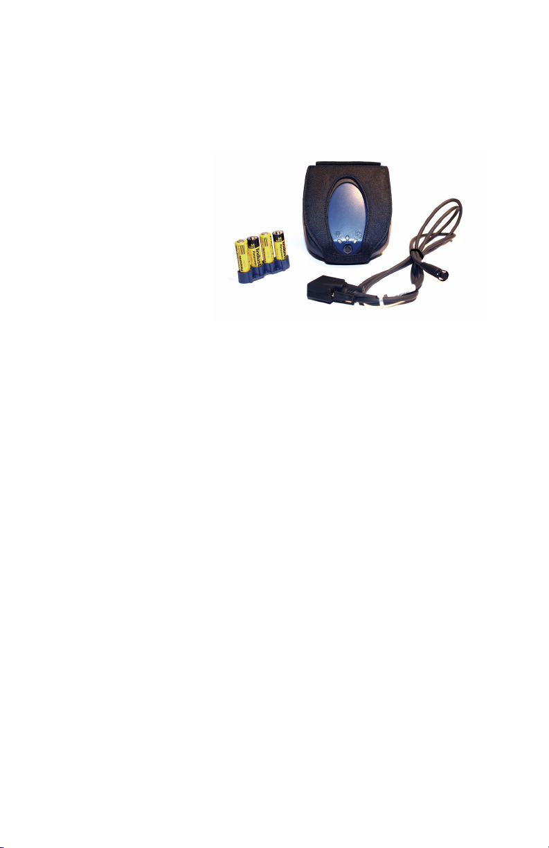
The following figure shows the MobileMapper Beacon system.
We have written this document to assist you with learning
how to use the MobileMapper Beacon system, how it oper
ates with GPS equipment, and provide some general information on Coast Guard beacon technology.
Key Features
• Fully integrated Coast Guard beacon receiver and
antenna
• All-day battery life using either four alkaline, 1.5-V Lithium or NiMH rechargeable AA-type batteries
• Integrated Bluetooth wireless technology for communications with the MobileMapper CE
• Convenient belt-mounted carrying system
• User interface includes a power button and status lights
• Conventional hard-wired serial port for communication
with other GPS equipment via a cable with standard DB9
connector.
-
2
Page 7
Note - Though the
MobileMapper Beacon
is primarily intended for
use with our
MobileMapper and
MobileMapper CE GPS/
GIS data collections systems, it may be used with
any GPS system that
support RTCM-based
real-time differential
corrections. In order to
connect to other devices,
you will need to ensure
the GPS supports either
Bluetooth wireless tech-
nology or an RS-232
serial port.
Introduction
The Thales MobileMapper Beacon system is an accessory to
the Thales MobileMapper CE GPS data collection system.
The MobileMapper Beacon is a self-contained, Coast Guard
beacon receiver system. It features an internal beacon re
ceiver and magnetic field beacon antenna, wireless communications, and a compartment for 4 AA batteries.
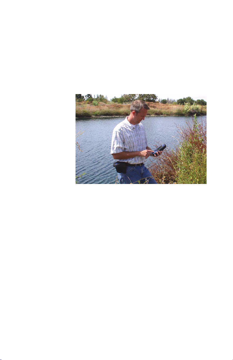
The following figure illustrates the use of the MobileMapper
Beacon.
Receiving Your Shipment
If you find that any of the items are damaged due to shipment, please contact the freight carrier immediately for assistance. If you find that the system is incomplete for some
reason, please contact your point of sale for assistance.
-
MobileMapper Beacon System
Each MobileMapper Beacon system is composed of:
• MobileMapper Beacon Coast Guard beacon receiver unit
• 4 AA Batteries
• Belt-mounted carrying system
• 1 battery clip for easy loading of batteries
• Warranty card
• User Manual
• A PC-interface cable for serial communications.
3
Page 8
Using the MobileMapper Beacon
User Interface
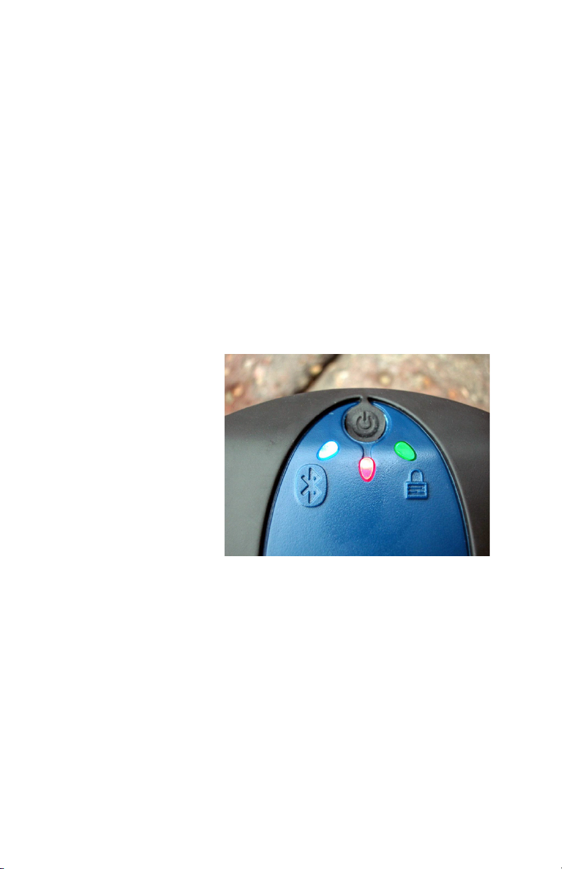
The MobileMapper Beacon user interface is located on the
top of the unit. This interface consists of a power button and
three lights. A red light next to the power button indicates the
unit is on. A green light comes on once the unit has locked
onto a DGPS transmitter with a signal-to-noise ratio greater
than seven and is sending the corrections to the GPS receiv
er. A blue light next to the Bluetooth symbol is illuminated
when the unit is sending the corrections to the GPS receiver
via the Bluetooth connection.
The following picture shows the status lights and power button located on the top surface of the product. Please note the
power button and indicator lights are visible through a cutout located on the top of the pouch, supplied with the system.
-
4
Page 9
This product is
intended for use with
regular 1.5-V,
rechargeable and nonrechargeable, AA bat-
teries. Do NOT use
higher voltage batter-
ies (including 3.6V Li-
SOCl2 AA cells) as
these will cause dam-
age to the unit.
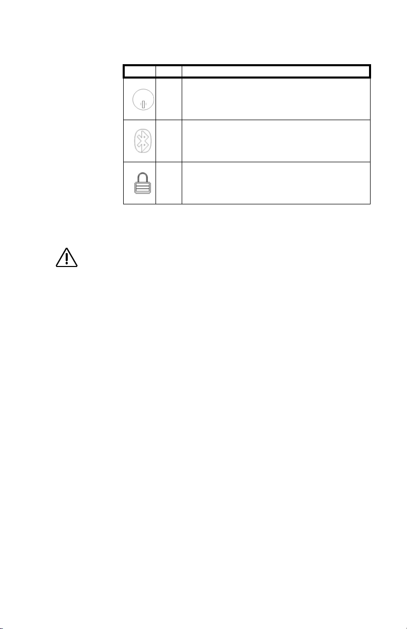
The following table provides detail regarding the status
lights.
LED Color Function
Power indicator - when the MobileMapper Beacon is powered,
this LED will solidly illuminate. Note: This LED does not have a
Red
label, but is connected to the Power Button to indicate what it
is for.
Bluetooth indicator - this LED will illuminate when there is a
Bluetooth connection between the MobileMapper Beacon and
Blue
a Bluetooth compatible device and off when there is no Blue
tooth connection.
Beacon lock indicator - this indicator will illuminate continuously when the MobileMapper Beacon has achieved a solid
Green
beacon lock with an SNR (signal to noise ratio) of greater than
7.
Powering the MobileMapper Beacon
The MobileMapper Beacon system includes four AA alkaline batteries for power. You may alternatively use four
1.5-V Lithium batteries (such as the Energizer® e² Lithium)
or four NiMH (nickel metal hydride) rechargeable batteries,
as long as you do not mix battery types.
NiMH batteries, being rechargeable, offer economy but if
you are going to work in cold weather, you should be aware
that the charge capacity of NiMH technology decreases with
falling temperatures.
Please also keep in mind that if you use NiMH batteries, they
need to be freshly charged before use if they are been stored
for a long period of time.
Although you may load individual batteries into the MobileMapper Beacon, the system includes two battery clips to
ease battery loading. You may insert four AA batteries into
each of the clips, drop one clip into the battery compartment
and store the spare clip in the mesh pouch on the side of the
belt-mounted carrying system.
-
5
Page 10
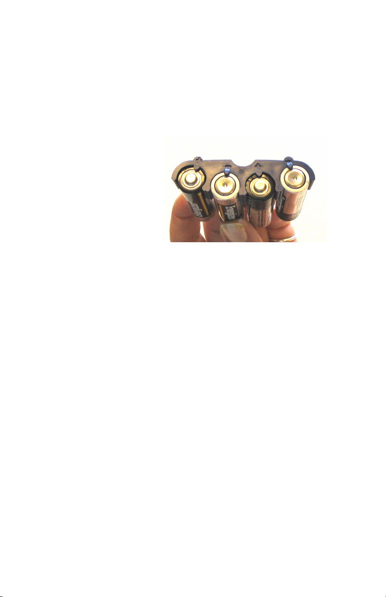
The easiest way to insert batteries into a clip is by sliding
them up from under the clip. There are some moulded stops
designed for the proper alignment of the batteries in the clip.
This ensures that the battery terminals make the proper con
tact when the compartment door is fastened to the unit.
It is important to insert the batteries into the clip with alternating polarity. A fully loaded clip is shown below.
As shown on this photo, the polarity of the batteries is positive, negative, positive, negative. You can easily slide the
batteries up and into the clip.
The battery clips are also marked with plus and minus signs
to indicate the polarity of the batteries. If you use batteries
without polarity markings, just remember that the flat end is
negative and the end with the raised knob is positive.
-
6
Page 11
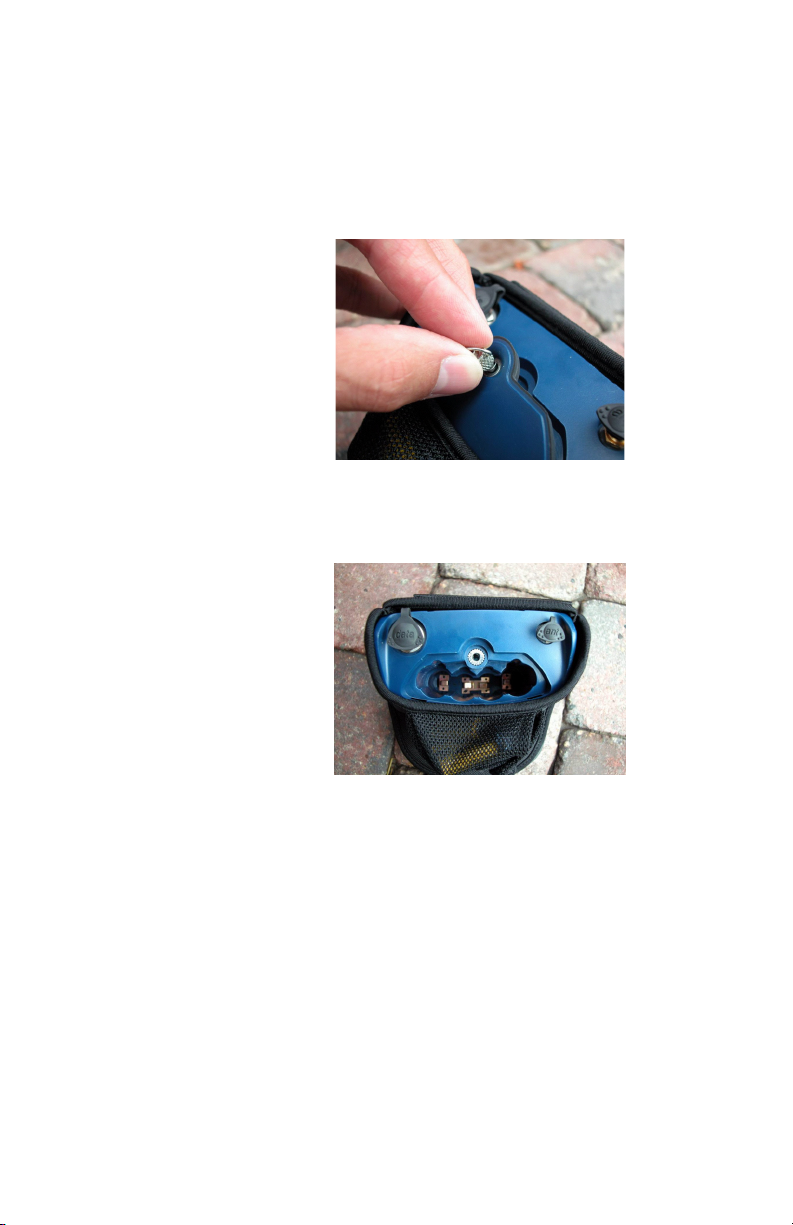
It is not necessary to remove the MobileMapper Beacon
from the belt-mounted carrying system in order to open the
battery compartment. Just unscrew the knurled silver knob
until you feel the compartment door come loose and pull the
door away from the unit.
You will find that the fastener disengages and 'pops' toward
you. You can then use the fastener to open the door.
At this point, you may load either four individual batteries
into the MobileMapper Beacon, or load the batteries into the
clip and insert the clip assembly into the battery compart
ment. The battery clip easily inserts into the compartment.
-
7
Page 12
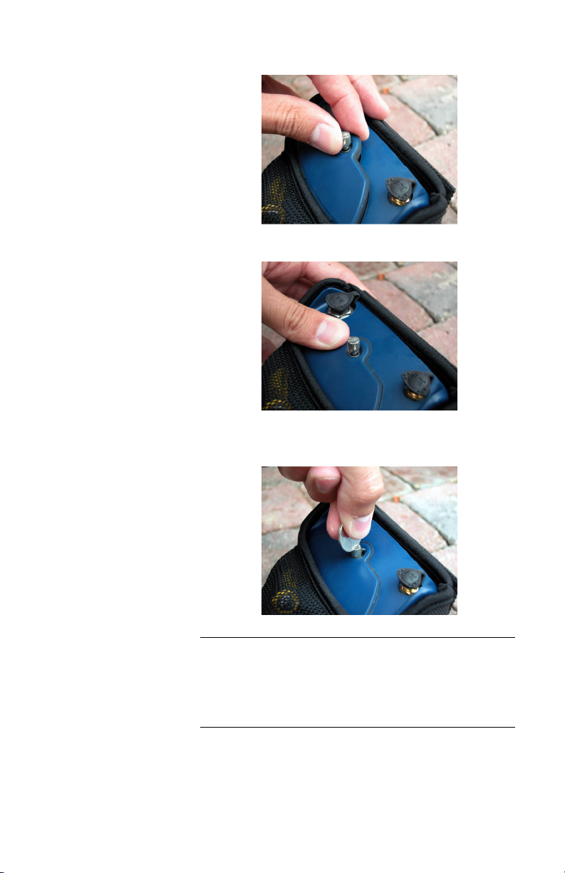
To secure the battery compartment door, slide it into place.
Now gently push the door down until the gasket engages.
Pressing the door down, screw the knurled knob into the unit
assuring a good seal.
Warn ing - Please use only batteries of the same type. Do not
mix alkaline batteries with 1.5-V Lithium or NiMH batteries.
Please do not mix batteries of different charge levels. This can
cause the batteries to fail, causing damage to you or the Mo
bileMapper Beacon.
-
8
Page 13
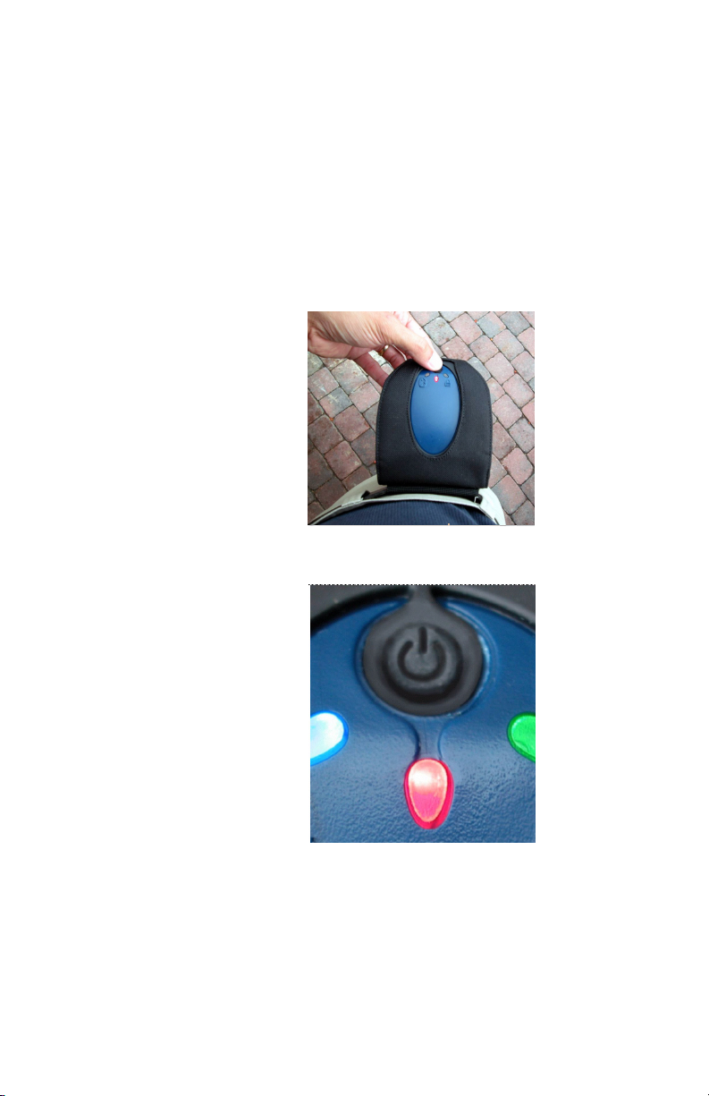
Powering the MobileMapper Beacon
To turn on the MobileMapper Beacon, press the black, recessed power button on the top of the unit as seen in the photographs below. When powered, the red LED light turns on.
When the MobileMapper Beacon is turned off, it still draws
a small amount of current from the batteries. If you will not
use the receiver for a number of weeks, you may wish to re
move the batteries so they do not lose their charge. You may
place the batteries in the belt-mounted carrying system so
you know to place them back in the receiver prior to use.
-
9
Page 14

Belt-mounting
The MobileMapper Beacon is designed to mount easily onto
a belt using the included carrying system. You may alterna
tively carry the Beacon in a backpack or mount it on a range
pole in some fashion. Wherever you carry the MobileMap
per Beacon, please be sure to separate it from your GPS receiver or any other electronic device (cell phone, PDA, etc.)
by at least 75 centimeters (30 inches) to prevent radio inter
ference. You should also keep the top of the Beacon horizontal to optimize signal reception. This is easy to do if you
place the Beacon on your belt on the hip opposite to the hand
you use to carry your MobileMapper or MobileMapper CE
receiver. For example, if you will carry the GPS receiver in
your left hand, place the MobileMapper Beacon on your
right hip. Doing this keeps the Beacon away from the GPS
receiver, it keeps the top horizontal and it allows you to
check reception status by looking at the LEDs on the top of
the unit.
The belt-mounted carrying system has an open bottom so
you can easily access the battery compartment, use an exter
nal beacon antenna or attach a serial data cable to the unit
without having to remove it from the carrying system.
-
-
-
-
10
Page 15

You can also use a serial
data cable to communi-
cate with the
MobileMapper CE. The
original (non-CE)
MobileMapper receiver
is not Bluetooth-
enabled, and so you
must use a cable link.
This is available as an
option.
Bluetooth Wireless Communications with MobileMapper CE
The MobileMapper Beacon's primary method of communicating coast guard beacon corrections to the MobileMapper
CE system is via an internal Bluetooth wireless communica
tions module. This module is a license-free transceiver that
may be used in majority of countries throughout the world,
and operates at 2.4 GHz.
Bluetooth wireless communications is a convenient method
to communicate between electronic devices, eliminating the
need for you to connect a cable between the MobileMapper
Beacon and the MobileMapper CE.
The MobileMapper Beacon contains a Power Class 1 Bluetooth enabled device that is capable of a maximum range of
100 m with another class 1 device. If you are communicating
with another device that is a Power Class 2, your range will
be limited to a maximum of 10 m.
As Bluetooth transmits and receives at 2.4 GHz, it is a line
of sight system. This means that the MobileMapper Beacon
and the receiving device require a line of sight between them
in order to communicate. This is critical if you are using the
two devices toward their maximum operating rate from each
other. For example, you may use the MobileMapper CE
away from a vehicle, with the MobileMapper Beacon sitting
on the roof instead of wearing it. In this case, both devices
must be able to 'see' each other and be within the range limit.
However, when operating the MobileMapper Beacon near
the other device, such as the MobileMapper CE, you do not
need a line of sight between the two products. In this case,
reflected signals can be tracked off the ground with success.
-
11
Page 16
Note - The Bluetooth
port will not be used for
firmware updates; it is
recommended you use
the serial port for any
software updates.
Establishing a Bluetooth Connection
For details regarding the process of connecting to the MobileMapper Beacon system with the MobileMapper CE,
consult the section below, "MobileMapper CE Bluetooth
Manager."
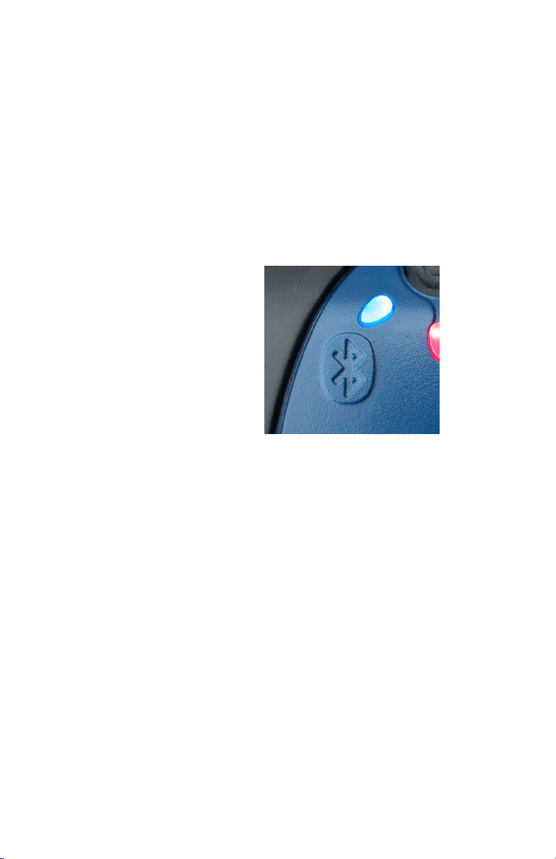
When the MobileMapper CE has established a Bluetooth
connection to the MobileMapper Beacon system, a blue
LED will illuminate on the top of the MobileMapper Bea
con. This blue LED is identified with the Bluetooth logo as
shown in the following figure. A successful Bluetooth con
nection between these devices will be present as long as the
blue LED light on the MobileMapper Beacon is on.
-
-
12
If you are using the MobileMapper Beacon system with an
alternate GPS system that uses Bluetooth communications,
please follow the instructions for that system on how to per
form a Bluetooth discovery and make a connection to the
MobileMapper Beacon system.
-
Page 17
When not using serial
communications, please
ensure that the rubber
boot is pushed onto the
data socket at all times.
This will protect the con-
nector from water and
dust.
Serial Communications
The second method of communicating with the MobileMapper Beacon is through a traditional RS-232 serial port. When
using a serial cable, you will not see the Bluetooth light illu
minate; however, serial data will be downloading into the
GPS system.
A PC-interface cable is supplied with the MobileMapper
Beacon system for serial communications. This cable will be
used for any firmware upgrade, if required, and for intercon
nection to GPS systems that do not support Bluetooth wireless communications.
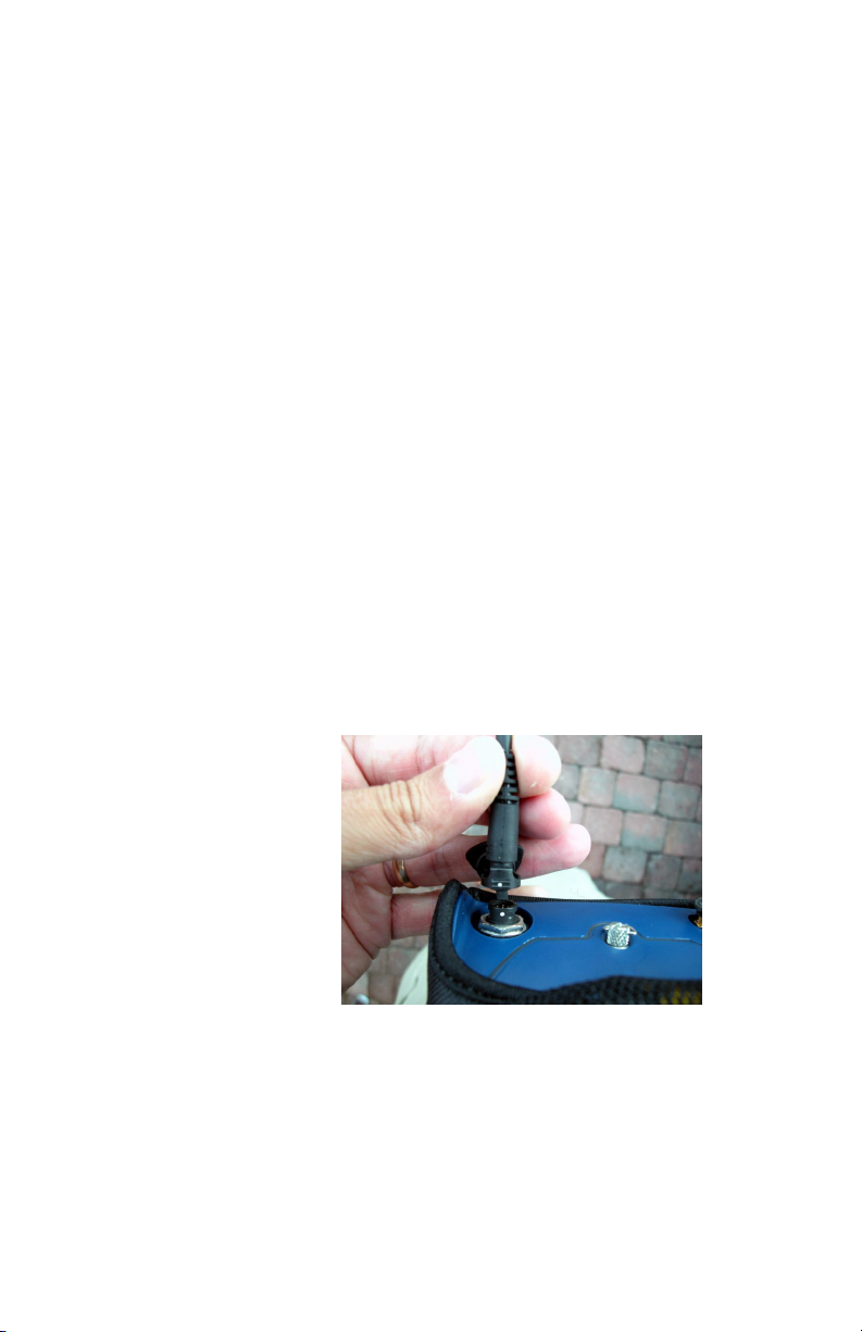
On the bottom of the MobileMapper Beacon system, you
will notice that beside the battery door, there is a rubber boot
that covers a data socket. Written on this rubber boot is the
word 'Data'. The round 7-pin connector of the PC-interface
cable plugs into this socket. There is a white dot on both the
socket and the 7-pin plug of the cable. To mate these connec
tors, align the two dots together and simply push the connector onto the socket. To remove the connector, you will need
to squeeze the two locking clips on either side of the 7-pin
connector of the cable.
To attach the serial cable to the MobileMapper Beacon, line
up the white dots on both connectors.
-
-
-
13
Page 18
In the event that you are
connecting the
MobileMapper Beacon
to a non-Thales-branded
GPS receiver, you may
need to plug a gender
changer and null modem
adapter into the DB9
end of the Beacon's
serial cable.
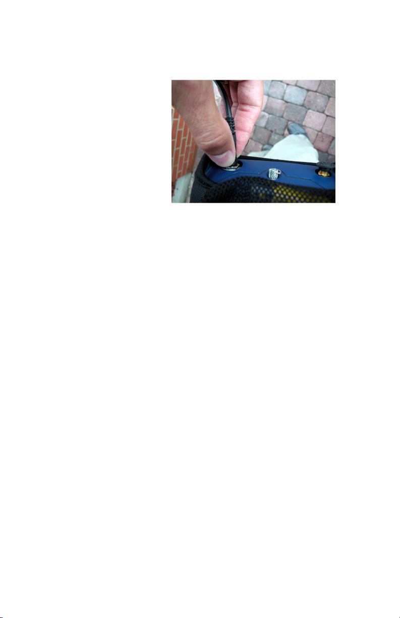
Using the optional serial
cable (P/N 980816), it is
easy to connect Thales
MobileMapper to
MobileMapper Beacon.
To remove the cable, squeeze the tabs on either side of the
cable and gently pull it out.
Serial Port Parameters
If you wish to use the MobileMapper Beacon with non-Thales GPS equipment without Bluetooth wireless technology,
you may need to use conventional serial communications be
tween the two systems. In this case, you will need to know
the port settings of the MobileMapper Beacon, which fol
low:
• Baud Rate: 4800
• Data bits: 8
• Stop bits: 1
•Parity: None
-
-
14
Page 19
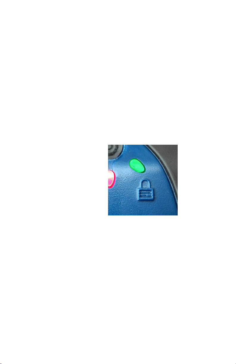
Beacon Lock
When a signal from a coast guard beacon station has been acquired, the green lock indicator light will illuminate as
shown below. If you are operating in a weak signal environ
ment, or with sufficient environmental noise to cause interference with the signal, this light will either be intermittently
illuminated or may not come on at all. We recommend that
you trouble-shoot a no-lock condition by using the Differen
tial GPS configuration tool supplied in the GPS Utilities
folder of the MobileMapper CE or the standalone Mo
bileMapper Beacon configuration utility that can be downloaded from ftp.thalesnavigation.com.
Using this tool, you can tune the Beacon to specific frequencies and coast guard beacon stations and monitor the current
frequency or station being used and the resulting reception
performance.
-
-
-
Knowing What Beacon Station To Use
Thales publishes a beacon listing that provides beacon station details around the world. Often, beacon site details
change or new stations are added, so please check with your
local Thales Navigation office for updates.
15
Page 20

To make sure that your
MobileMapper CE
handheld will
automatically connect to
the same MobileMapper
Beacon device each time
you turn on the system,
in the context-sensitive
menu tied to the chosen
Bluetooth
Serial Port, check Auto
Connect.
MobileMapper CE Bluetooth Manager
In order to use corrections from the MobileMapper Beacon,
the MobileMapper CE's Bluetooth Manager must first be
used to discover the Beacon product, and then establish a
connection.
To access the Bluetooth Manager:
• Tap the Windows butterfly icon in the lower left of the
MobileMapper CE screen with the stylus.
• Then access Settings>Control Panel>BTManager. The Blue-
tooth icon will appear in the system tray.
To turn the Bluetooth function on or off, you will need to tap
on the Bluetooth icon. A window will pop up. From here,
you will be able to turn this communications feature on or
off. Ensure that your MobileMapper Beacon system is near
by and powered. When turned on, the Bluetooth Manager
will proceed to initiate a discovery of nearby Bluetooth-ca
pable systems. The results of this process are displayed below the on and off buttons.
When the discovery is complete, you should see the MobileMapper Beacon system displayed as 'MMBEACON
xxxxx', where 'xxxxx' is the last five digits of the multimedia
access code (MAC) address, indicated on the serial label of
the MobileMapper Beacon system.
If you press the 'plus (+)' box beside the 'MMBEACON
xxxxx' device, you will notice that the supported service is
'BLUETOOTHSERIAL'. Using the stylus, tap and hold on
the service name. A menu will pop up and choose 'connect'.
In a few moments, you should see the Bluetooth indicator
light on the MobileMapper Beacon illuminate. The Mo
bileMapper CE will also indicate a Bluetooth connection.
-
-
-
16
Page 21
A standalone
MobileMapper Beacon
Configuration Utility is
also available at
ftp.thalesnavigation.com.
This tool allows you to
tune the receiver and
monitor the reception in
Windows XP/2000 or
Windows Mobile 2003
environment.
Windows CE Configuration Utility
As part of our MobileMapper CE GPS Utilities, we have a
utility that allows you to modify the correction source used
by the GPS. Within this interface, you will also have access
to communicate with the MobileMapper Beacon system.
This utility allows you to tune the receiver to a specific bea
con by frequency or station name, and monitor the reception
performance of the system as measured by the Signal to
Noise Ratio (SNR).
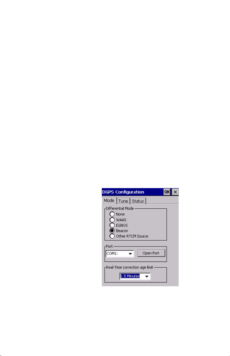
Differential Mode
The following figure illustrates the differential GPS mode of
operation. There are three choices from which you may
choose. The first choice is to not use any corrections. The
second, and default, is to use corrections from the internal
WAAS / EGNOS demodulator.
To use the MobileMapper Beacon with the CE system, you
must choose the
bileMapper CE system to 'look' for correction data incoming
from a certain port. To use the beacon corrections, you must
first establish a Bluetooth connection using the Bluetooth
Manager discussed earlier.
Beacon option. This will instruct the Mo-
-
17
Page 22

Tuning the Beacon Frequency
There are two methods that you can use to tune the beacon
receiver inside the MobileMapper Beacon. The first method
is the default mode, which is automatic operation. The sec
ond mode is manual operation where you specify the frequency to which you want the receiver to tune.
We recommend that you use automatic tuning when operating in an area where you are unsure of the stations available
or their frequency details. If you know the station name or
frequency, we recommend you tune the receiver manually.
This way, you know for certain which station that is being
used. Further, we recommend that you consistently use the
same station for all your work in a particular region. This
will ensure the best consistency of differentially-corrected
position data. As you may know, errors seen at a GPS base
station may not be the same as seen by your GPS receiver.
Due to the difference between these errors, a bias can creep
into the positioning solution. This is the nature of local area
differential GPS. Using the same beacon station helps to en
sure that your data is as consistent as possible.
If, for some reason, the beacon to which you want to tune is
not operating, you will obviously need to use another station,
if available. Beacon stations are reliable, but sometimes need
to be maintained, or may be hit by lightning. Most beacon
stations are designed so that most parts that could fail for one
reason or another, are backed up by an identical, redundant
piece of equipment. It's not often that a beacon will fail, and
remain down, without redundant equipment taking over. You
should follow up with your service provider (most often a
Coast Guard, but sometimes a Port Authority) for details on
a particular station.
Our Configuration utility allows you to change the way that
your beacon system is tuned. The following discussion de
scribes how you may tune your system using this software
tool.
Within the DGPS Configuration window, tap the 'Tune' tab
at the top of the window. The following figure displays the
content of the associated tab.
-
-
-
18
Page 23
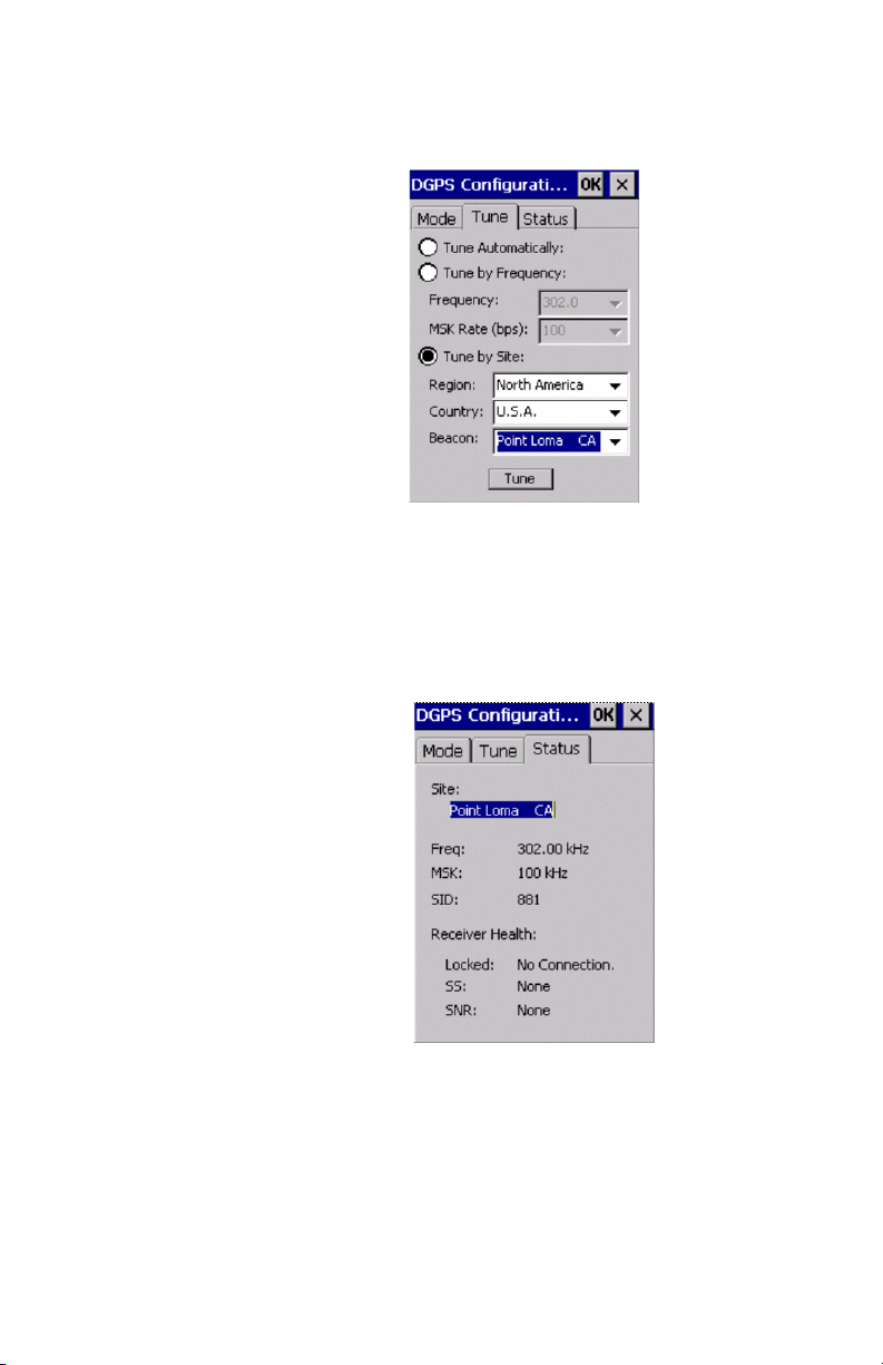
You will see that you're free to either tune by the frequency
and MSK (data) rate of the station, or by station name, cho
sen by region, country, and beacon name.
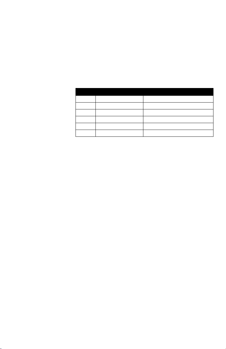
The following window displays the content of the 'Status'
tab. You will see in this window the current tuning settings,
including the station name, frequency, but rate, and station
ID. Below this information is the lock condition, signal
strength (SS) measured in dBµV, and signal to noise ratio
(SNR) measured in dB.
-
The following section provides guidance on evaluating reception quality, given a particular SNR.
19
Page 24
Monitoring Reception Performance
Beacon reception performance is described by a signal to
noise ratio (SNR) number. Essentially what this number in
dicates is how much the signal 'peaks' above the noise floor.
A taller signal would mean better reception performance
than a shorter signal above the noise floor. The SNR is mea
sured in decibels (dB).
The following table describes reception performance based
on the SNR indicator.
SNR Receiver Description Approximate Data Throughput
>25 Excellent 100% data throughput
20 to 25 Very Good 100% data throughput
15 to 20 Good Good data throughput up to 100%
10 to 15 Moderate Moderate to good data throughput
7 to 10 Intermittent Low data throughput
<7 No Lock No data throughput
Beacon Interference
The signals transmitted from Coast Guard beacon stations
are very weak and can be jammed by noise emitted from
electronics. All electronics emit some type of radio noise.
Depending on the amplitude and frequency bands that they
emit, it has the potential to interfere with beacon reception.
There are other sources of noise, such as power lines, engine
electronics of vehicles, power transformers, and the like.
The MobileMapper Beacon system is able to provide diagnostic information to the DGPS Configuration application
that you can run on your PC or on the MobileMapper CE
system. This utility can allow you to monitor the current re
ception performance of the MobileMapper Beacon system.
This will tell you how well it's receiving the signal compared
to the amount of noise present in the environment.
-
-
-
20
Page 25

To ensure that you provide the MobileMapper Beacon with
the best chance to receive a relatively noise-free signal, here
are some precautions that you should be aware of:
• If you use a belt-worn pager or mobile phone, ensure that
you wear it on the opposite side of your body so that it's
away from the MobileMapper Beacon.
• Wear the MobileMapper Beacon on the same side of
your body as write with a pen. For instance, if you are
right-handed, wear the beacon system on your right hip.
• If, for some reason, you have a notebook or tablet computer nearby, ensure that it's a few feet away from the
MobileMapper Beacon system.
We have found that personal digital assistants (PDA's) emit
noise that can mask the beacon signal, but they often do not
emit as much noise as a full computer system. You may find
that there's little interference from such a system within one
or two feet.
Troubleshooting Reception
The first thing to confirm when troubleshooting beacon reception problems is to monitor the lock LED indicator. If it's
on, the receiver is locked. If you find that it's on most of the
time, chances are that there's sufficient data being passed to
the GPS system to allow differential correction to happen. If
you find that the light is most often off, or always off, this
would be an indication of reception problems.
Reception problems can be confirmed using the Configuration Utility described previously, by monitoring the SNR
value. If you find the SNR is very low, you should confirm
that the frequency or station to which the receiver is tuned,
is the correct one. If it is not, re-tune the receiver to the cor
rect station or frequency.
If you find that the receiver is tuned to the right station, you
need to determine if the problem is associated with too much
noise in your area, use of the product in a region of very
weak signal, a service-side failure, or a failure of the receiver
system itself.
-
21
Page 26

Note - If you see '-100' at
any point in the SNR or
SS fields, this just means
that the receiver is
changing frequency or
data rate of the signal
automatically. This will
not happen in when the
system has been tuned in
manual mode by select-
ing the frequency or sta-
tion name.
If you are able to communicate with the receiver with the
Configuration Utility, you know the receiver is functioning
in some capacity. The next step is to monitor the signal
strength. If you find that the signal strength is very close to
zero or negative, this indicates the possibility of an antenna
failure.
If you find the signal strength is higher than approximately
10 dB, the antenna should be functioning correctly. The next
step is to determine what is causing reception problems. It
will either be environmental noise or weak signal. If it's a
noise problem, the signal strength will likely be high. For ex
ample, if you see an SS value of say 50 dB, and an SNR of
5, you can be assured that the environment is jamming the
reception of the signal. There's not much that can be done in
a situation like this unless you can identify the source of
noise. Sometimes this takes a bit of looking around your en
vironment to determine.
-
-
22
Page 27

Coast Guard DGPS Service
The MobileMapper Beacon receives differential correction
data transmitted by coast guard stations located in many re
gions throughout the world.
This chapter aims to provide you with practical knowledge
of this coast guard service, to empower your use of this prod
uct.
Radiobeacon Range
The broadcasting range of a 300 kHz beacon is dependent
upon a number of factors including transmission power, free
space loss, ionospheric state, surface conductivity, ambient
noise, and atmospheric losses.
The strength of a signal decreases with distance from the
transmitting station, due in large part to spreading loss. This
loss is a result of the signal's power being distributed over an
increasing surface area as the signal radiates away from the
transmitting antenna.
The expected range of a broadcast also depends upon the
conductivity of the surface over which it travels. A signal
will propagate further over a surface with high conductivity
than over a surface with low conductivity. Lower conductiv
ity surfaces such as dry, infertile soil, absorb the power of the
transmission more than higher conductivity surfaces, such as
sea water or arable land.
A radiobeacon transmission has three components: a direct
line of sight wave, a ground wave, and a sky wave. The line
of sight wave is not significant beyond visual range of the
transmitting tower, and does not have a substantial impact
upon signal reception.
The ground wave portion of the signal propagates along the
surface of the earth, losing strength due to spreading loss, at
mospheric refraction and diffraction, and attenuation by the
surface over which it travels (dependent upon conductivity).
-
-
-
-
23
Page 28

The portion of the beacon signal broadcast skywards is
known as the sky wave. Depending on its reflectance, the
sky wave may bounce off the ionosphere and back to Earth
causing reception of the ground wave to fade. Fading occurs
when the ground and sky waves interfere with each other.
The effect of fading is that reception may fade in and out.
However, this problem usually occurs in the evening when
the ionosphere becomes more reflective and usually on the
edge of coverage areas. Fading is not usually an issue with
overlapping coverage areas of beacons and their large over
all range.
Atmospheric attenuation plays a minor part in signal transmission range, as it absorbs and scatters the signal. This type
of loss is the least significant of those described.
Radiobeacon Reception
Various sources of noise affect beacon reception, and include:
- Engine noise
- Alternator noise
- Noise from Power lines
- DC to AC inverting equipment
- Electric devices such as PDA's, cellular phones,
CRT's, electric motors, fans, and solenoids
-
24
Noise generated by this type of equipment can mask the beacon signal, reducing or impairing reception, depending on its
magnitude and proximity. Weak sources of noise can still
jab reception of a beacon signal. Under this type of condi
tion, however, removal of the noise source by a number of
inches is often sufficient to improve reception.
Your MobileMapper CE system (and some 3rd-party GPS
equipment) allow you to set the maximum differential age.
Setting the age to a higher value allows any reception distur
bances to be buffered by the increased age. If you find that
you're operating in an area of high noise, you may find that
if you allow the beacon receiver to lock in a quieter area, that
you have sufficient time before the differential time-out to
conduct the work that you require.
-
-
Page 29

Note - Due to effects of
spatial decorrelation, we
recommend that you
consistently use a specific beacon station as
much as possible. If, for
some reason this station
is not available, you will
need to determine if a
secondary station is
available.
Spatial Decorrelation
Depending on the range from yourself to the beacon, the environmental conditions may differ between the base station
site and your location. This difference will show up as an ad
ditional error in positioning, and is referred to as spatial
decorrelation.
The additional degradation will depend on the difference in
observed orbit and ionospheric errors between the reference
station and your GPS system. A general rule of thumb would
be a 1 m error for every 100 miles of distance to the beacon
station. This error is often seen as a bias in positioning, re
sulting in a position offset. The scatter of the receiver is likely to remain close to constant.
Coast Guard Beacon vs WAAS/EGNOS
Coast Guard beacon DGPS has certain strengths in comparison to WAAS and vice versa, which are important to know
when deciding what correction source to use. Both services
are provided without user fees, so your choice of which sys
tem to use must be made according to different criteria.
Benefits of Coast Guard Beacon
• Low Frequency - the low frequency of beacon is a signif-
icant strength when working in areas where a line of
sight is blocked to WAAS or EGNOS, such as under can
opy or in urban canyon. The frequency of beacon is
located below AM radio stations. As you've likely expe
rienced of AM radio stations, compared to higher frequency FM stations, AM radio is more robust, and
diffracts well around obstacles, such as buildings, high
way overpasses, etc. With often only two WAAS or
EGNOS satellites available, and sometimes only one, it's
possible that GPS can still be tracked effectively under
tree canopy. Being low frequency, the beacon signal is
able to penetrate trees very well, while a WAAS/EGNOS
lock cannot be attained reliably.
-
-
-
-
-
25
Page 30

• The low frequency has benefit in penetrating tree-cover,
but it is also susceptible to man-made sources of noise
from various electronics or electrically driven equip
ment. This susceptibility shows up in reduced SNR,
which could lead to less reliable reception.
• ·Local Area Service - beacon is a local area service
where only one station is providing correction data to the
user-base. This is a strength such that it provides good
quality corrections when near the beacon site. Spatial
Decorrelation does enter the picture as you operate away
from the station. However, it's possible that Coast Guard
beacon DGPS could handle large ionospheric distur
bances better than WAAS/EGNOS, although a rare condition.
-
-
Benefits of WAAS/EGNOS
• High Frequency - WAAS / EGNOS transmit with a
pseudo-GPS signal at L1 frequency. This signal will be
available anywhere the GPS receiver's antenna can 'see'
the satellite. This provides a very wide operating area,
with the exception of behind certain large objects that
can mask the signal.
• Robust Reception - Being line of sight, and being transmitted on L1 frequency, the WAAS/EGNOS signal is
typically easy to acquire. Interference with GPS is typi
cally rare, which provides you with a robust service,
when the satellite(s) can be viewed.
• Wide Area Service - WAAS and EGNOS use a wide area
format for their service. A network of reference stations
compute corrections for the specific errors in the GPS
service (ionosphere, satellite orbit, and clock correc
tions). It's possible that the reference stations in the network are not of sufficient density, and they cannot pick
up subtle changes in the ionosphere.
-
-
26
Page 31

This could result in a similar error as spatial decorrelation in Coast Guard beacon, however, this is likely to be
less significant. More significant is that the ionospheric
map is downloaded to users only every 5 minutes.
Recent past has shown that the ionosphere, during peak
solar activity, can change more quickly than this update
rate, causing a significant source of error.
This is a very rare condition. Solar activity can be monitored by consulting various Web sites, such as
www.spaceweather.com
Radiobeacon DGPS
Radiobeacons conforming to the standards of the International Association of Lighthouse Authorities broadcast a
limited selection of RTCM SC-104 messages, including
message types 1, 2, 3, 5, 6, 7, 9, and 16.
- A DGPS beacon will broadcast either Type 1 or Type
9 messages, both of which contain similar informa
tion. These two messages contain pseudorange corrections and range rate corrections to each GPS
satellite.
- The Type 2 message contains delta differential corrections that are used when the remote receiver is
using a different satellite navigation message than
used by the base station.
- The Type 3 message contains the position of the beacon's reference station, often accurate to within centimeters with respect to the WGS-84 reference
datum.
- The Type 5 message contains GPS constellation
health information used for improving tracking per
formance of a GPS receiver
- The Type 6 message contains null information, and is
broadcast so that a beacon receiver demodulating the
data from the broadcast does not lose lock when the
beacon station has no new data to transmit.
-
-
27
Page 32

- The Type 7 message contains the radiobeacon almanac information composed of location, frequency,
service range, and health information of sister sta
tions for the currently tuned beacon.
- The Type 16 message provides users with a 90 character text string that may contain information regarding the status of the system, weather warnings, etc.
Radiobeacon DGPS is often referred to as a local-area service, as the data broadcast is appropriate for use within the
coverage range of the station.
-
Radiobeacon Coverage
The following figure shows the approximate radiobeacon
coverage throughout the world. In this figure, light shaded
regions note current coverage, with beacon stations symbol
ized as white dots. Please note that the extent of coverage
shown is approximate. To get the most up to date informa
tion on Coast Guard DGPS beacon services, we recommend
that you contact your local Coast Guard or Port Authority.
-
-
28
Page 33

Page 34
MOBILEMAPPER BEACON
USER MANUAL
Thales
Mobile Mapping Solutions Contact Information
+1 909 394 5000 • Fax +1 909 394 7050
In USA
Toll Free (Sales in USA/Canada) 1 800 922 2401
In South America +56 2 273 3214 • Fax +56 2 273 3187
Email [email protected]
In Singapore +65 6235 3678 • Fax +65 6235 4869
In China +86 10 6566 9866 • Fax +86 10 6566 0246
mail
E
mobilemappingapac@thalesna
e
anc
r
In F
+33 2 28 09 38 00 • F
y
man
er
In G
In Russia +7 095 956 5400 • Fax +7 095 956 5360
In UK +44 199 385 2436 • Fax +44 870 429 9236
In the N
mail
E
W
©2005 Thales S.A. All rights reserved. MobileMapper is a trademark of Thales.
+49 81 6564 7930 • F
lands
ether
mobilemappingemea@thalesna
e
eb sit
www
.thalesgr
ax +33 2 28 09 39 39
ax +49 81 6564 7950
+31 78 61 57 988 • F
om/na
.c
oup
tion.com
viga
ax +31 78 61 52 027
viga
tion
viga
tion.c
om
P/N 631236-01C
 Loading...