

Texecom Veritas RKP Installation Manual

THANK YOU FOR VOTING TEXECOM
THANK YOU FOR VOTING TEXECOM
THANK YOU FOR VOTING TEXECOMTHANK YOU FOR VOTING TEXECOM
Remote Keypad
INSTALLATION MANUAL

1 INSTALLATION
The Veritas Remote Keypad (RKP) is suitable for use with
the Veritas range of Control Panels.
1. Up to 6 keypads may be used in total.
2. The Unset LED on the keypad will flash during entry
or to indicate a power fault.
1.1 Mounting
Open the keypad by carefully inserting a small flat-blade
screwdriver into either half of the double slot at the base of
the unit. Gently twist the screwdriver to ease the retaining
clip upwards. Do NOT use excessive force. The front and
flap can now be removed.
The PCB assembly is hinged for easy access. Alternatively
the PCB assembly can be unclipped and completely
removed if required.
Mount the keypad using at least two appropriate
countersunk screws (no larger than No. 6). A keyhole slot
has been provided to assist mounting and aid levelling.
1.2 Wiring
It is strongly recommended that the system is completely
powered down (mains and battery) before wiring a keypad.
2 INS037-5
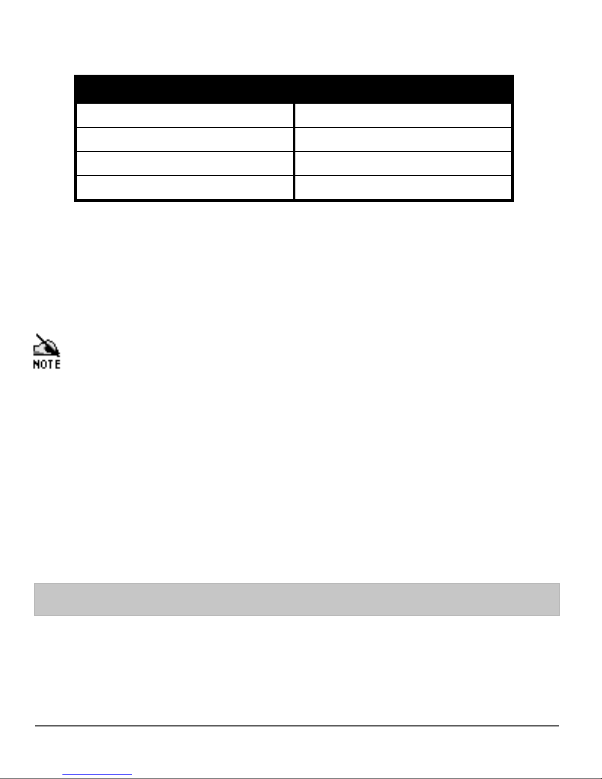
Connect the keypad to the control panel using 4-core cable
as follows:
Keypad Control Panel
12V AUX+
0V AUX-
TT
RR
Please see Figure 1 on back page.
Up to six keypads may be connected in parallel (“star”) or
series (“daisy-chain”) or any combination.
1. When using long cable runs or connecting keypads
in series (“daisy-chain”) ensure that the voltage at
the keypad is not more than 2V less than the
voltage at the control panel.
2. When using 6-core or 8-core cable always use the
spare cores to “double-up” on 0V. This will allow
longer cable runs particularly when connecting
keypads in series (“daisy-chain”). As a rule
“trebling-up” on 0V will be more beneficial than
“doubling-up” on 12V and 0V.
1.3 Selecting an Address
Each keypad MUST be given a different address using the
DIP switch on the side of the PCB as follows:
INS037-5 3
 Loading...