

Page 1
Page 2

2 INS154-4
Contents
Section Page
1. Installation 3
1.1 Mounting the Unit 3
1.2 Patented Engineer Hold-Off Mode 3
1.3 Installing the Unit 3
1.3.1 Optional “Battery First” Connection Method 4
1.4 Installing Multiple Units 5
1.4.1 SCB Mode 5
1.5 Commissioning 6
2. Servicing 6
3. Safety 7
4. Technical Specification 8
5. Warranty 10
6. Registered Installer Application Form 11
Page 3

INS154-4 3
1. Installation
1.1 Mounting the Unit
Select a suitable position to mount the unit, which satisfies the following criteria:
• Highly prominent for maximum deterrence
• Additional shelter (e.g. under the eaves) is an advantage
• High enough to be out of normal reach to deter tampering
• Safe ladder access
• Good cable access
In addition to the corner screw fixing points, the unit also has a central keyhole to
simplify mounting and aid levelling.
Four screws and wall plugs are required for mounting the backplate to an even
surface. An additional screw may be required to provide wall tamper by fitting
through the screw hole next to the dual tamper microswitch. In doing so, care must
be taken to leave the screw head slightly proud to ensure that the microswitch
remains level and closes correctly when the outer cover is fitted.
For safety reasons the unit must be mounted securely on a suitable wall.
For maximum weatherproofing the unit should be flat to the wall.
For brick walls, BS 4737 specifies a minimum of three No. 10 steel screws
penetrating the brick (not the mortar or facing) by at least 40mm into suitable wall
plugs.
1.2 Patented Engineer Hold-Off Mode
For safety reasons, each Texecom sounder and strobe unit incorporates a unique
patented engineer Hold-Off mode. This mode prevents the unit from self-activating
during installation and maintenance, thereby allowing only bona fide engineers
access to the unit without any loss of tamper protection.
1.3 Installing the Unit
Connect the unit to the control panel as follows:
A (12V ) Permanent Positive Supply
B (BELL) Negative Applied Output to Activate Siren
C (TAMP) Negative Removed on Tamper Input
D (0V) Permanent Negative Supply
S (STRB) Negative Applied Output to Activate Strobe
Although the unit has been designed to be compatible with a wide range of control
panels, for optimum performance, it is highly recommended that the unit should be used
with Texecom's ran
g
e of control panels.
Page 4

4 INS154-4
The following table illustrates how to connect the unit to the Texecom range and
other control panels:
A B C D S
Texecom Control Panel A B C D S
C&K Active 5, Securit BELL + S - 24 TAMPER AUX - ST Menvier TS510, 700, 800 BELL 12V BELL TRIG BELL TMP 0V STB
Scantronic 9448 to 9800 +12V BELL TR 0V STR
When connecting the unit to the control panel, it is recommended that wiring should
be connected to the unit first and the control panel second. The unit should then be
initially powered from the control panel. If the tamper circuit is open the siren will
sound for 5 seconds after which it will automatically enter Hold-Off mode and disable
Self-Activate (S/A) on tamper. This will prevent the unit from self-activating as long as
the tamper circuit remains open. An open tamper circuit is indicated by only the
left-hand side LED flashing. Connect the battery by moving the red battery wire from
the “N/C” (No Connect) terminal to the “Battery +” terminal. Fit the outer cover and
secure with the M6 screw(s) provided.
When the outer cover is replaced and the tamper circuit is closed, the LEDs will
alternate rapidly, confirming that the tamper circuit is secure and signalling that S/A
on tamper will be re-enabled within 2 minutes, after which the LEDs will alternate
slowly to signal normal operation. If the tamper circuit is re-opened within the 2
minute period, then Hold-Off mode will be restored.
If the unit is powered up with the tamper circuit closed it will NOT sound for 5
seconds and will NOT enter Hold-Off mode. In order to disable the S/A function,
before the cover is removed, Hold-Off mode should be invoked as for servicing (see
Section 2).
For safety reasons the strobe is disabled during Hold-Off mode.
Hold-Off mode is immediately cancelled when the sounder is activated from the
control panel.
1.3.1 Optional “Battery First” Connection Method
Hold-Off mode automatically cancels when both the tamper circuit is closed and
power is supplied from the control panel. This allows installation engineers to power
the unit from the internal battery and fit the outer cover, knowing that the unit cannot
self-activate until after power has been supplied from the control panel.
If the tamper circuit is closed and the unit is powered by the battery only, the right
LED will flash quickly to signal that the unit cannot self-activate until power has been
supplied from the control panel.
Prolonged “battery first” connection without power from the control panel may cause
permanent damage to the internal battery. Texecom recommend that the unit is
initially powered on battery only for no longer than 24 hours.
Page 5
INS154-4 5
1.4 Installing Multiple Units
If more than one unit is connected to an installation, the current demand may exceed
the rated current output of the control panel. This can be avoided by selecting the
SCB mode on all but one of the connected units.
1.4.1 SCB Mode
In this mode the unit draws the majority of its sounding current from the built-in
battery rather than from the control panel. Although volume is somewhat reduced,
lowering the current demand on the control panel will enable the connection of
additional sounder units. To select SCB Mode, the unit should first be powered from
the built-in battery by connecting the red battery wire from the “N/C” (No Connect)
terminal to the “Battery +” terminal. The unit will automatically enter Hold-Off mode to
disable Self-Activate (S/A) on tamper, this will prevent the unit from self-activating
until both the tamper circuit is closed and power is supplied from the control panel.
Move the jumper JP1 to the SCB position before the unit is connected to the control
panel.
If the tamper circuit is closed and the unit is powered by the battery only, the right
LED will flash quickly to signal that the unit cannot self-activate until power has been
supplied from the control panel.
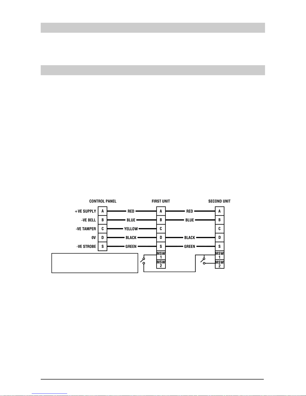
The following diagram illustrates how to wire multiple units together:
If the first unit is opened it will self-activate and a tamper will be signalled to the
control panel. If the second unit is opened both units will self-activate and a tamper
will be signalled to the control panel.
When selecting SCB mode the battery must be connected before power is supplied
from the control panel. If multiple units are connected to a single control panel
without SCB mode selected, the sounding current may exceed the rated current of
the control panel. If a unit is powered from a control panel with SCB mode selected
but without the battery connected, the unit will not operate correctly due to the lack of
power provided.
The built-in battery will only be partially charged on delivery.
Remove tamper wire from MSW 2 on first unit
and connect to spare core. On second unit
connect spare core into MSW 1.
Page 6
6 INS154-4
1.5 Commissioning
Most control panels have a method of testing the siren and strobe, which should be
utilised for final testing. Failing this, simply arm the system and cause an alarm to
confirm correct operation. Temporarily disconnect the positive supply to the unit at
the control panel to confirm that the sounder self-activates.
The strobe does not self-activate.
Some control panels have an option to select the sounder cut-off time. The unit will
sound for either 15 minutes or for the panel cut-off time, whichever is the shorter.
2. Servicing
CAUTION: BEFORE OPENING THE COVER ALLOW AT
LEAST 3 MINUTES AFTER THE LAST STROBE FLASH
Most control panels have a method of testing the siren and strobe, which should be
utilised. Failing this, simply arm the system and cause an alarm to confirm correct
operation. Temporarily disconnect the positive supply to the unit at the control panel
to confirm that the sounder self-activates.
The strobe does not self-activate.
Some control panels have an option to select the sounder cut-off time. The unit will
sound for either 15 minutes or for the panel cut-off time, whichever is the shorter.
For safety reasons if it is necessary to inspect the unit, the Self-Activate (S/A) on
tamper function should be disabled before the cover is removed. This is achieved by
using the unit’s unique patented engineer Hold-Off mode. This is invoked by
activating and de-activating the strobe three times within 30 seconds. Most control
panels have a method of testing the strobe, which should be utilised. Failing this the
strobe can be manually activated by connecting the S (STRB) wire to 0V at the
control panel. Hold-Off mode is shown to be active with the tamper circuit secure by
the right LED only flashing.
If the tamper circuit is not opened then Hold-Off mode will automatically start to
cancel after 15 minutes, indicated by the LEDs alternating rapidly to signal that S/A
on tamper will be re-enabled within a further 2 minutes.
Once the outer cover is removed the left LED only will flash to indicate that the
tamper circuit is open.
Please note, it cannot be guaranteed that the battery is fully charged on
installation. When commissioning, the unit may require to be powered from
the control panel for a period of time before the battery is sufficiently
charged for self-activation.
Page 7
INS154-4 7
When the outer cover is replaced, and the tamper circuit is closed, the LEDs will
alternate rapidly, confirming that the tamper circuit is secure and signalling that S/A
on tamper will be re-enabled within 2 minutes, after which the LEDs will alternate
slowly to signal normal operation. If the tamper circuit is re-opened within the 2
minute period, then Hold-Off mode will be restored.
Summary of LED States
Slow flashing LEDs Normal operation
Left LED flashing only Hold-Off active, tamper circuit open
Right LED flashing only Hold-Off active, tamper circuit closed
Fast flashing LEDs Hold-Off active but will cancel within 2 minutes
If Hold-Off mode is invoked but the tamper circuit is not opened within 15 minutes
then Hold-Off will automatically start to cancel, indicated by the LEDs alternating
rapidly for a further 2 minutes.
For safety reasons the strobe is disabled during Hold-Off mode.
Hold-Off mode is immediately cancelled when the sounder is activated from the
control panel.
3. Safety
INSTALLATION AND MAINTENANCE BY
QUALIFIED SERVICE PERSONNEL ONLY
All strobes produce hazardous voltages. However, the unit includes dual circuit safety
interlocks. When the strobe is de-activated it invokes a final flash to discharge the
high voltage. Back-up circuitry guarantees discharge of the high voltage within 3
minutes.
For your own safety be sure to observe the following precautions
when installing and servicing the unit:
• NEVER remove the cover when the strobe is flashing
• WAIT 3 minutes after the strobe stops flashing before removing the cover
• AVOID touching the part of the PCB labelled “Warning High Voltage”
The unit incorporates software which disables the strobe whilst the tamper switch
remains open. This is a safety feature and cannot be disabled.
The piezo drive produces high voltages when the siren is sounding. While not
directly hazardous, these voltages will cause discomfort and should be avoided,
particularly when using tools or a ladder.
The piezo transformer TF1 will be hot during and after sounding. While not directly
hazardous, touching it when hot will cause discomfort and should be avoided,
particularly when using tools or a ladder.
Page 8
8 INS154-4
Failure to observe the following precautions regarding the battery could lead to the
danger of heating, ignition or explosion:
• Do not throw into a fire
• Do not heat
• Do not over-charge
• Do not reverse charge
• Do not short-circuit
• Do not disassemble
• Replace only with the same or
equivalent type
Always observe local regulations when disposing of a battery.
Plastic bags can suffocate - always dispose of packaging carefully.
4. Technical Specification
Environmental
Volume
Azura 360, Tempest:
109dB Peak at 1m (A Weighting, 90°)
Odyssey 1E, 2E, 3E & 4E:
109dB Peak at 1m (A Weighting, 90°)
Odyssey 1, 2, 3 & 4:
115dB Peak at 1m (A Weighting, 90°)
Cut-Off Time:
≤15 minutes
Waterproof Coating: Conformal
Operating Temperature:
-25°C (-13°F) to +55°C (+131°F)
Storage Temperature:
-25°C (-13°F) to +60°C (+140°F)
EMC Environment: Residential / Commercial /
Light Industrial / Industrial
Electrical
Supply Voltage: 12VDC (nominal)
Current Drain (typical at 12VDC)
Quiescent: 15mA
Strobe: 110mA
Sounder
Azura 360, Tempest: 300mA
Odyssey 1E, 2E, 3E & 4E: 300mA
Odyssey 1, 2, 3 & 4: 425mA
Standby Battery
Type: NiMh Stack
Voltage: 7.2VDC (nominal)
Capacity: 320mAh
Flash Tube: 1Ws
Flash Rate: 1Hz (typical)*
†
Discharge Time (≤≤≤≤60VDC): ≤180 seconds
Comfort LEDs
Brightness: 100mcd (typical)
Flash Rate (tamper secure): 1Hz alternating (typical)
* The flash rate will reduce to 0.125Hz after flashing for one hour (1 flash every 8
seconds). This is a software feature to reduce power consumption and cannot be
disabled.
† The flash rate may reduce to 0.5Hz for supply voltages less than 12V
DC.
Page 9
INS154-4 9
Physical
Material
Azura 360, Tempest: 3mm polycarbonate
Odyssey 1E, 2E, 3E & 4E: 3mm polycarbonate / 3mm ABS
Odyssey 1, 2, 3 & 4: 3mm polycarbonate
Orientation
Azura 360, Tempest: Vertical or horizontal
Odyssey 1, 1E, 3 & 3E: Vertical
Odyssey 2 & 2E: Horizontal
Odyssey 4 & 4E: Vertical or horizontal
Mounting: Corner mounting points plus central
keyhole(s)
Tamper Detection
Azura 360, Tempest: Wall and lid
Odyssey 1E & 2E: Wall and screw
Odyssey 1, 2, 3 & 4: Wall, screw and lid
Odyssey 3E & 4E: Wall and lid
Dimensions
Azura 360: 319mm x 196mm x 77mm
(12.56" x 7.80" x 3.64")
Tempest: 316mm x 205mm x 89mm
(12.44" x 8.07" x 3.50")
Odyssey 1 & 1E: 318mm x 201mm x 66.5mm
(12.52" x 7.91" x 2.62")
Odyssey 2 & 2E: 382mm x 242.2mm x 76mm
(15.03" x 9.53" x 2.99")
Odyssey 3 & 3E: 315mm x 306mm x 78mm
(12.40" x 12.04" x 3.07")
Odyssey 4 & 4E: 310mm x 196mm x 58.5mm
(12.20" x 7.71" x 2.30")
Packed Weight
Azura 360, Tempest: 1250g (44oz) approx.
Odyssey 1, 1E, 3, 3E, 4 & 4E: 1250g (44oz) approx.
Odyssey 2 & 2E: 1600g (56oz) approx.
Standards
Safety: Conforms to European Union (EU) Low
Voltage Directive (LVD) 73/23/EEC
(amended by 93/68/EEC).
EMC: Conforms to European Union (EU)
Electro-Magnetic Compatibility (EMC)
Directive 89/336/EEC (amended by
92/31/EEC and 93/68/EEC).
Security Specific: Conforms to EN50131-1/PD6662
Grade 3, Env Class IV Requirements
To comply with EU Directives the unit MUST ONLY be connected to a fused
power source (≤5A) supplied from an isolating transformer.
The CE mark indicates that this product complies with the European requirements for
safety, health, environmental and customer protection.
Page 10

10 INS154-4
5. Warranty
All Texecom products are designed for reliable, trouble-free operation. Quality is
carefully monitored by extensive computerised testing. As a result the Azura 360,
Tempest, Odyssey 1E, Odyssey 2E, Odyssey 3E and Odyssey 4E are covered by a
two year warranty against defects in material or workmanship (details on request).
The Odyssey 1, Odyssey 2, Odyssey 3 and Odyssey 4 are covered by a five year
warranty.
Because the Azura 360, Tempest and Odyssey Series are not complete alarm
systems but only a part thereof, Texecom cannot accept responsibility or liability for
any damages whatsoever based on a claim that a unit failed to function correctly.
Due to our policy of continuous improvement Texecom reserve the right to change
specification without prior notice.
Azura 360, Tempest and Odyssey are trademarks of Texecom Ltd.
Page 11
INS154-4 11
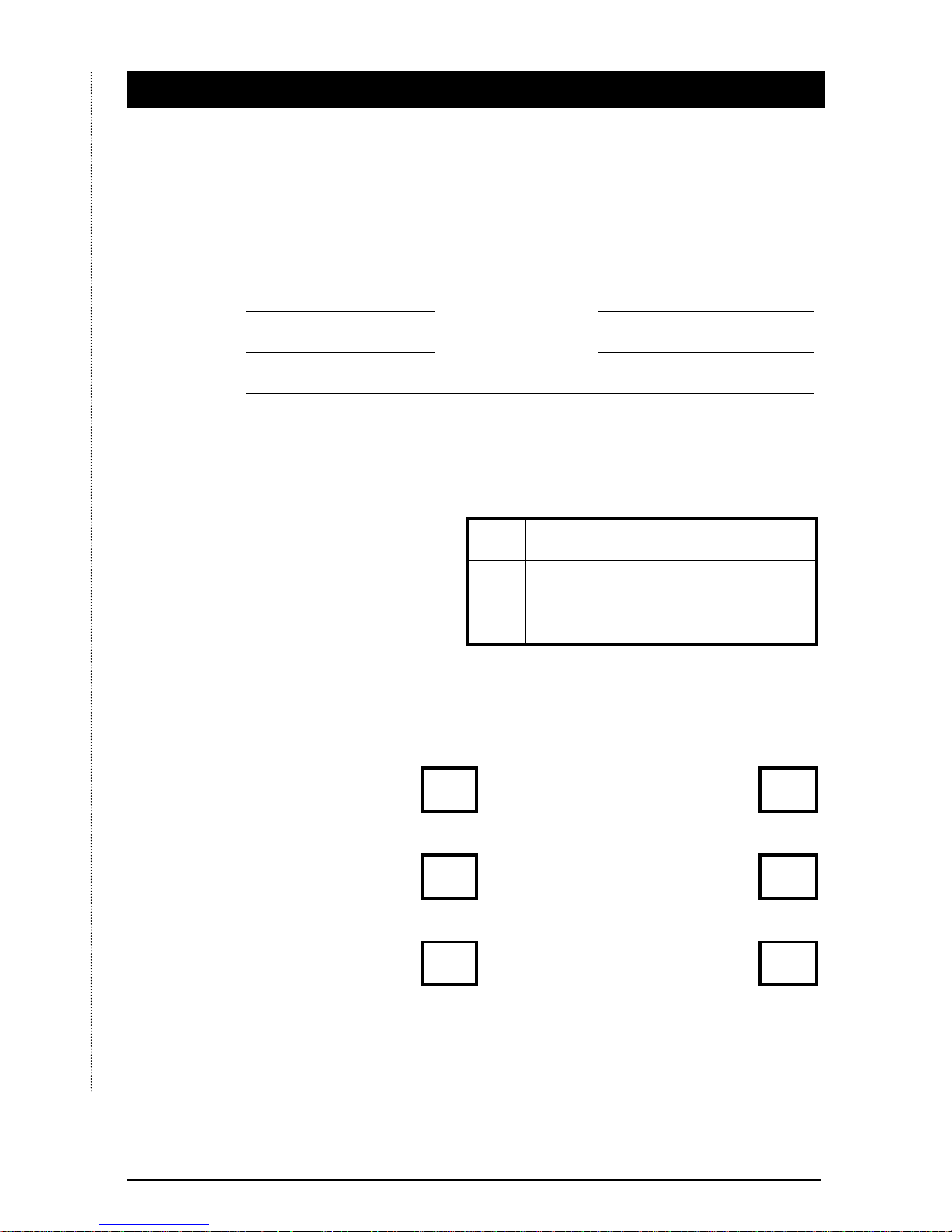
6. Registered Installer Application Form
Partially Completed Forms CANNOT be accepted.
Please use Black Ink and Block Capitals.
Name: Position:
Company: Fax:
Tel: E-Mail:
Mobile: Website:
Address:
Country: Postcode:
Which Distributors do you buy from? 1
(Indicate at least one). 2
3
How many of the following products do you currently install each month?
Motion Detectors: Control Panels (Domestic):
Perimeter Detectors: Control Panels (Commercial):
Smoke Detectors: External Sounders:
UK installers: Fax back to 01706 223450 or post to the address overleaf.
International installers: Fax back to 44 161 8815147.
Alternatively register online at www.texe.com
Page 12

INS154-4
There’s only ONE way to get
FREE
TECHNICAL SUPPORT...
REGISTER!
And receive the following exclusive benefits:
• Access to the Secure Area of the Texecom Website
• Freephone Technical Helpline*
• Free Product Voucher*
• Free Product Training*
• Latest Product Information
Register online at www.texe.com or simply complete the
form on the reverse of this page and return it to Texecom to
become a Registered Texecom Installer.
*Available for UK Registered Installers only.
Texecom Limited. Bradwood Court, St. Crispin Way, Haslingden,
Lancashire BB4 4PW.
UK Technical Support: 08456 300 600
(Calls charged at 3.36 pence per minute from a BT landline. Calls from other networks may vary)
International Technical Support: +44 1278 411707
Email: [email protected]
© Texecom Limited 2007
 Loading...