

Texecom Ricochet Impaq Contact-W Instruction Manual
INS 468-7
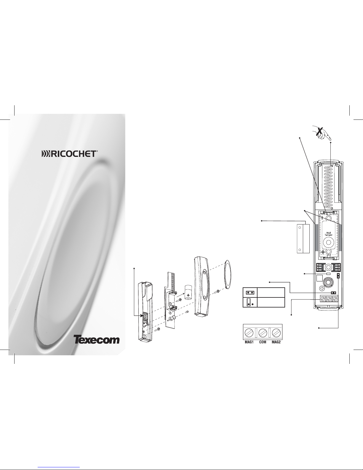
ASSEMBLY
For rear tamper - fix both the detector AND the rear tamper insert
to the mounting surface. Activation of rear tamper will damage
product.
Rear Tamper Insert
Relearn
MAG1 COM MAG2
Reed
Disable
Reed
Switch
Reed Disable
Magnet
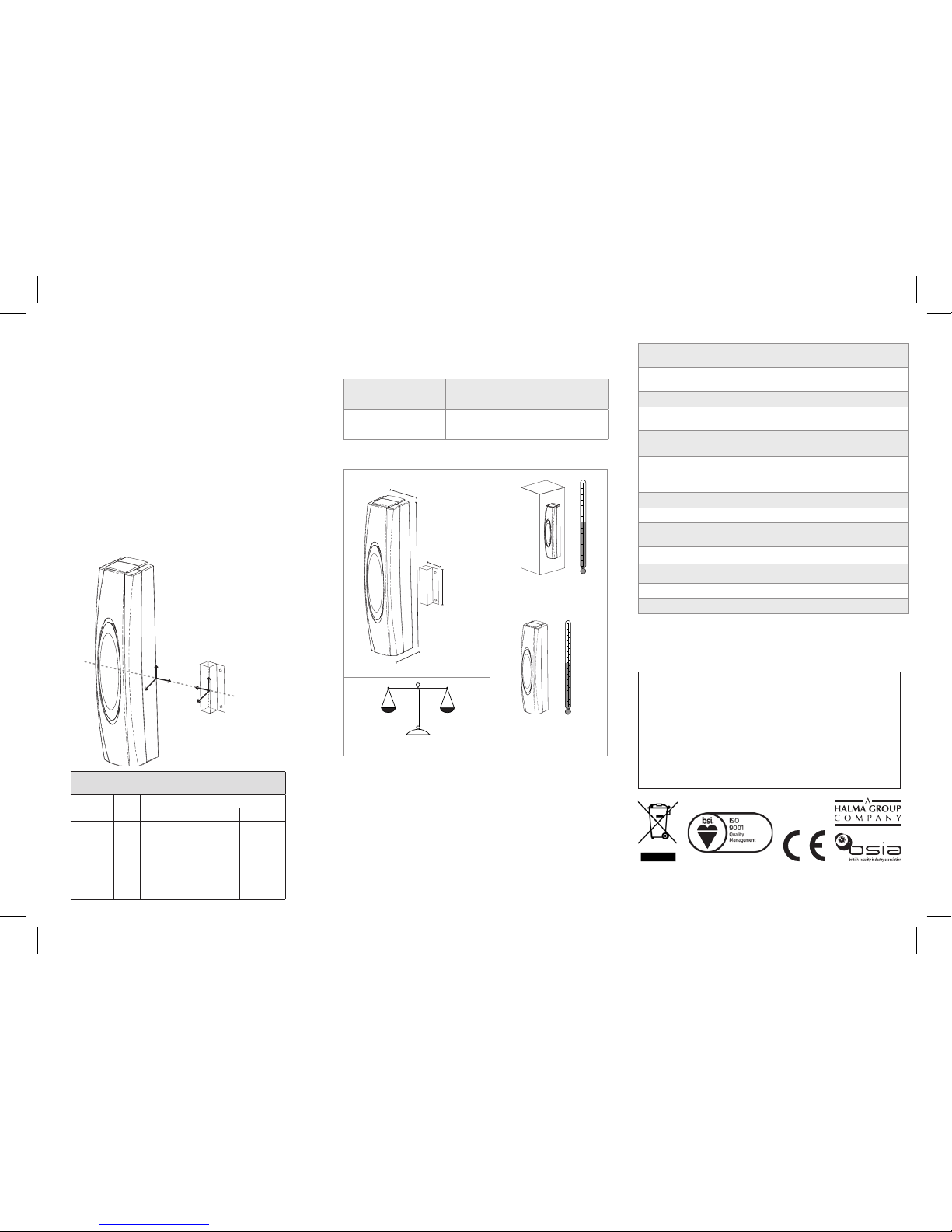
Non-Ferrous Mounting Material
• Maximum Break = 30mm
• Minimum Make = 15mm
Ferrous Mounting Material
• Maximum Break = 15mm
• Minimum Make = 5mm
Note: Values depend on
mounting material. See Fig.1
Disabled
Enabled
Battery
Only replace with 3V Lithium CR123A.
Battery Safety
• Do not throw into a fire
• Do not heat
• Do not charge
• Do not short circuit
• Do not disassemble
• Replace only with same or equivalent
type
• Always observe local regulations when
disposing of a battery
• Detector will transmit low battery warning
when battery needs replacing
Relearn
Place jumper on Relearn
pin header and insert battery to learn device.
For wiring external
wired contacts/switches
LED
INTRODUCTION
• For wireless connectivity, detailed programming and system
set-up instructions please refer to the compatible RICOCHET™
technology enabled Premier Elite wireless expander
instructions.
• Featuring RICOCHET™ wireless technology the Impaq
Contact-W is designed for professional security installations.
• When using the Impaq Contact-W on an Entry/Exit route, or a
24HR door, or where chime is required, the device attributes
should be left at default “Always Awake”.
• Please see the Premier Elite 8XP-W/32XP-W Installation Manual
for details of how to change the device attributes.
Instruction Manual
Premier Elite Impaq Contact-W
LED STATUS INDICATION
Only available in walktest mode
(See Premier wireless expander instructions)
STANDARDS
Impaq and the wireless logo are trade marks of Texecom Ltd. © 2012
The Impaq Contact-W is protected by European Registered Design. No:
269188-000 INS468-7
WARRANTY
2 year replacement warranty (excludes battery).
The Impaq Contact-W is designed to detect the open-
ing of a door/window and activate an alarm control panel.
As the Impaq Contact-W is not a complete alarm system, but
only a part thereof, Texecom cannot accept responsibility or
liability for any damages whatsoever based on a claim that
the Impaq Contact-W failed to function correctly.
Due to our policy of continuous improvement Texecom
reserves the right to change specification without prior
notice. All specifications are measured at 20ºC (68ºF).
Made In
England
ADDITIONAL INPUTS 1 & 2
Flashing Green:
With all contacts secure, will flash
every 3 seconds.
Red:
Indicates either the reed switch or
external contacts are active.
The Impaq Contact-W has 2 additional inputs. These may be used
for any N/C device and utilise wireless signal transmission to the
receiver. Typical examples for use are:-
• Any locally powered device with a N/C output e.g. Smoke
detectors, Glass Break detectors, Movement Sensors, Flood
detectors etc.
• Any non-powered N/C device, e.g. Additional magnetic
contacts, xed PA buttons etc.
• The in-built reed switch can be disabled.
• Conguration and programming options are detailed in the
Premier wireless expander installation manual.
• Certain features and functions are control panel software
dependent.
-35°C (-31°F) to
+60°C (+140°F)
88g (3.1oz) approx.
-10°C (14°F) to
+55°C (+131°F)
25mm (1”)
26mm (1”)
130mm
(5.1”)
33mm
13mm
Alarm Systems:
EN50131-2-6, EN50131-5-3,
EN50131-1, PD6662, Grade 2 Class II*
EMC:
EN50130-4:2011
ETSI EN301 489-03 V1.4.1
R&TTE: ETSI EN300-220 (V2.1.1)
Environmental: EN50130-5:2011
Frequency Band:
868.0 - 868.6 MHz / 433.05 - 434.79 MHz
866.0 - 866.6 MHz • See product label
Product Type:
GBC1000-2 Frequency 868MHz
GBC2000** Frequency 433MHz
GBC3000** Frequency 866MHz
Receiver: Category 1, Class 2
Receiver LBT (Listen Before Talk) Yes
Transmitter Duty
Cycle
868Mhz<1%, 433Mhz<10%
Low Voltage Signal 2.85V
Operating Voltage 3V
Maximum current 32mA
Quiescent current 60uA
MAGNET POSITIONING
Fig.1
Y
X
Z
Y
X
Z
Magnets can be installed either side of the unit.
(All distances in mm)
Material Axis
Approach
Min
Removal
Min Max
NonFerrous
X
Y
Z
14
6
18
16
8
20
24
16
28
Ferrous
X
Y
Z
5
5
13
6
6
15
12
12
21
*Certied by Telecation BV ** Not INCERT approved.
Certificate Number: FM 35285
Min Approach - Magnets must be mounted within this distance
of the contact, to ensure closure.
Min Removal - Minimum distance at which the contact may
open. - This should be considered as the maximum distance that
the door / window can move when it is secured.
Max Removal - Maximum distance at which the contact will
open.
 Loading...