

Page 1

INSTALLATION
MANUAL
Remote Keypads
THANK YOU FOR VOTING TEXECOM
THANK YOU FOR VOTING TEXECOMTHANK YOU FOR VOTING TEXECOM
THANK YOU FOR VOTING TEXECOM
Page 2

Contents Premier LCD & LCDL Installation Manual
2 INS180
Contents
1. Overview............................................................................................ 3
General ..................................................................................................................3
Keypad PCB Layout .............................................................................................4
2. Installation......................................................................................... 6
Mounting................................................................................................................6
Connecting Keypads ............................................................................................7
Wiring the Network .......................................................................................7
Network Connections ...................................................................................8
Cable Distances............................................................................................8
Overcoming Voltage Drop ............................................................................9
Installing a Power Supply .............................................................................9
Selecting an Address .........................................................................................10
Wiring Zones to the Keypad ..............................................................................11
Double Pole ................................................................................................11
End Of Line .................................................................................................11
Connecting Speakers to the Keypad................................................................12
Connecting the Keypad Output.........................................................................12
Other Features ....................................................................................................13
Programmable ‘Info.’ LED ..........................................................................13
Adjustable Backlighting ..............................................................................13
Testing the Keypad.............................................................................................13
3. Specifications.................................................................................. 14
Electrical ..............................................................................................................14
Environmental .....................................................................................................14
Physical ...............................................................................................................15
Standards ............................................................................................................15
Warranty ..............................................................................................................15
Page 3

Premier LCD & LCDL
LCDLLCDL
LCDL Installation Manual Overview
INS180 3
1. Overview
General
The Premier LCD and LCDL keypads are only compatible with the following control panels:
• Premier 888
• Premier 8168
Any combination of Premier LCD and LCDL keypads can be used.
Keypads, zone expanders and output modules are all connected to the same network
terminals located at the bottom left hand corner of the control panel and may be
connected serially (daisy chain), in parallel (star) or any combination of the two.
! "
A maximum of 8 keypads, 8 zone expanders and 4 output modules can be
connected to each network.
Keypad Features
• 32 character English text display (Premier LCD only)
• Large 32 character English text display (Premier LCDL only)
• 2 fully programmable Double Pole or End Of Line zones
• 1 fully programmable output (100mA ‘-ve’ applied)
• Programmable ‘Info.’ LED
• Fully adjustable backlighting, normally bright, dim or off, changing to
bright during entry or for 8 seconds following any key press
• Built in piezo sounder
• Speaker driver output (Premier LCDL only)
Page 4
Overview Premier LCD & LCDL Installation Manual
4 INS180
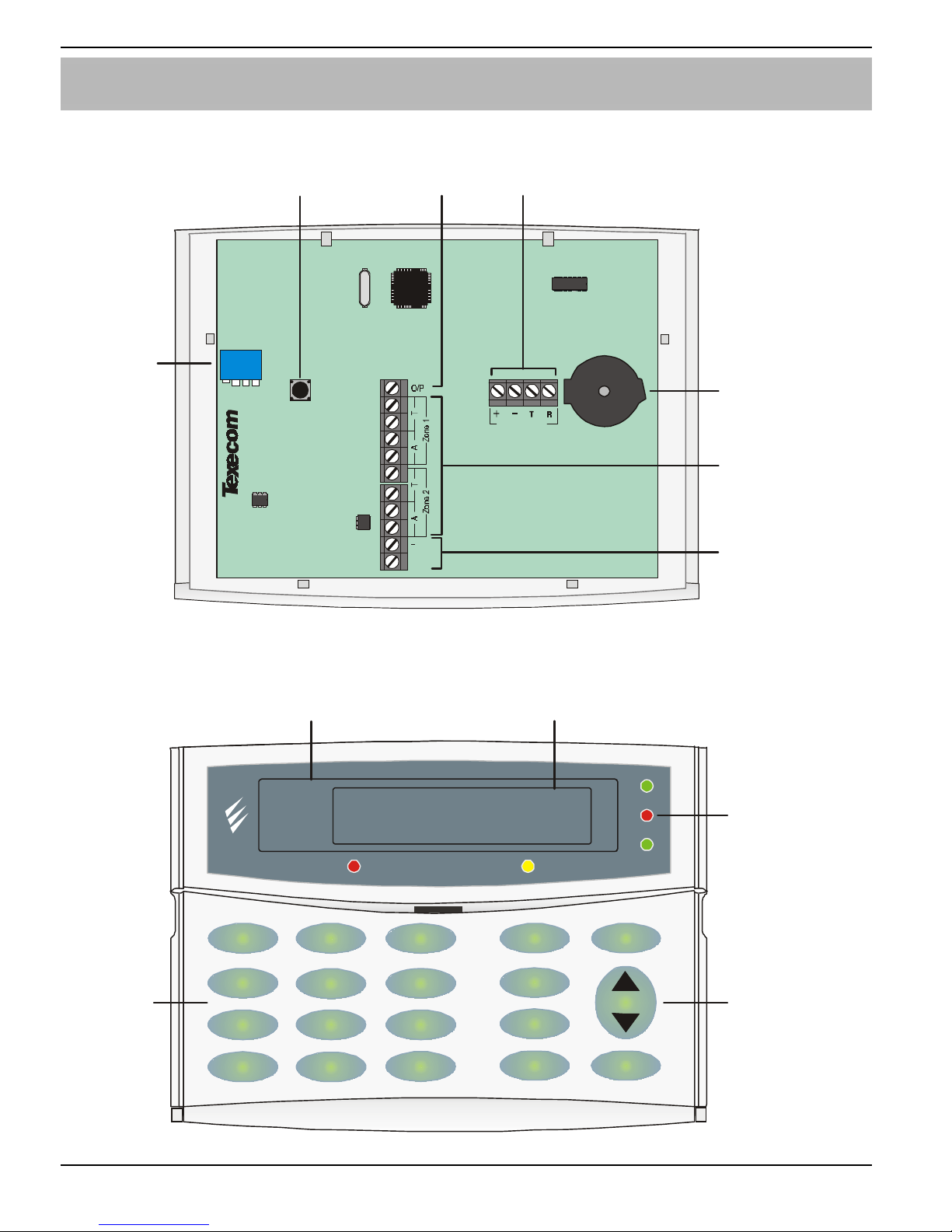
Keypad PCB Layout
SPK
2431
NE TWOR K
+
Address
Switch
Output
Network
Te rm in a ls
Tam p er
Switch
Speaker Output
(Only)LCDL
Zones 1 & 2
Piezo
Sounder
Premier LCD
Display
Programmable
‘Info.’ LED
Area
Yes
Part
Chime
Omit
Reset
Menu
Power
Info.
Ready
ServiceOmit
Function
Keys
Premier LCDL
Large Display
Screen Not Shown
Normal
Keys
2
abc
No
1
3
def
6
mno
9
wxyz
5
jkl
8
tuv
0
4
ghi
7
pqrs
_
Page 5

Premier LCD & LCDL
LCDLLCDL
LCDL Installation Manual Overview
INS180 5
Tamper Switch
This is the cover tamper switch and provides tamper protection for the keypad.
Output
This output is a low current (100mA ‘-ve’ applied) and can be used to drive auxiliary
devices such as LED’s, sounders or relays etc.
Network Terminals
These terminals must be connected to the corresponding terminals on the control
panel or previous device (see page 8 for wiring details). The ‘+’ and ‘–’ terminals
provide power for the keypad whilst the ‘T’ transmits data and ‘R’ receives data.
! "
When connecting devices to a keypad that require 12V power i.e. PIR’s etc,
the power must be connected to the ‘+’ and ‘-’ of the network terminals.
Address Switch
This switch sets the address of each keypad (see page 10 for details).
! "
Never set two keypads on the same network to the same address.
Piezo Sounder
The sounder provides audible indication of the system status i.e. alarm tones,
entry/exit tones, service tones, warning tones and key presses etc.
Zones 1 & 2
These terminals provide the connections for the 2 zones. Each zone can be wired
as Double Pole or End Of Line (2k2 EOL & 4k7 contact).
Speaker Output (Premier LCDL Only)
These terminals can be used for connecting up to one 16Ω or two 8Ω loudspeakers
(see page 12 for wiring details).
Premier LCD & LCDL Display
The 32-character display is used to show the status of the system and to view
system data.
‘Info.’ LED
The ‘Info.’ LED can be programmed to mimic the keypad output or show the armed
status of an area. For details on programming the ‘Info.’ LED please refer to the
Premier 888/8168 Installation Manual.
Normal & Function Keys
These keys are used for operating and programming the system.
Page 6
Installation Premier LCD & LCDL Installation Manual
6 INS180
2. Installation
Mounting
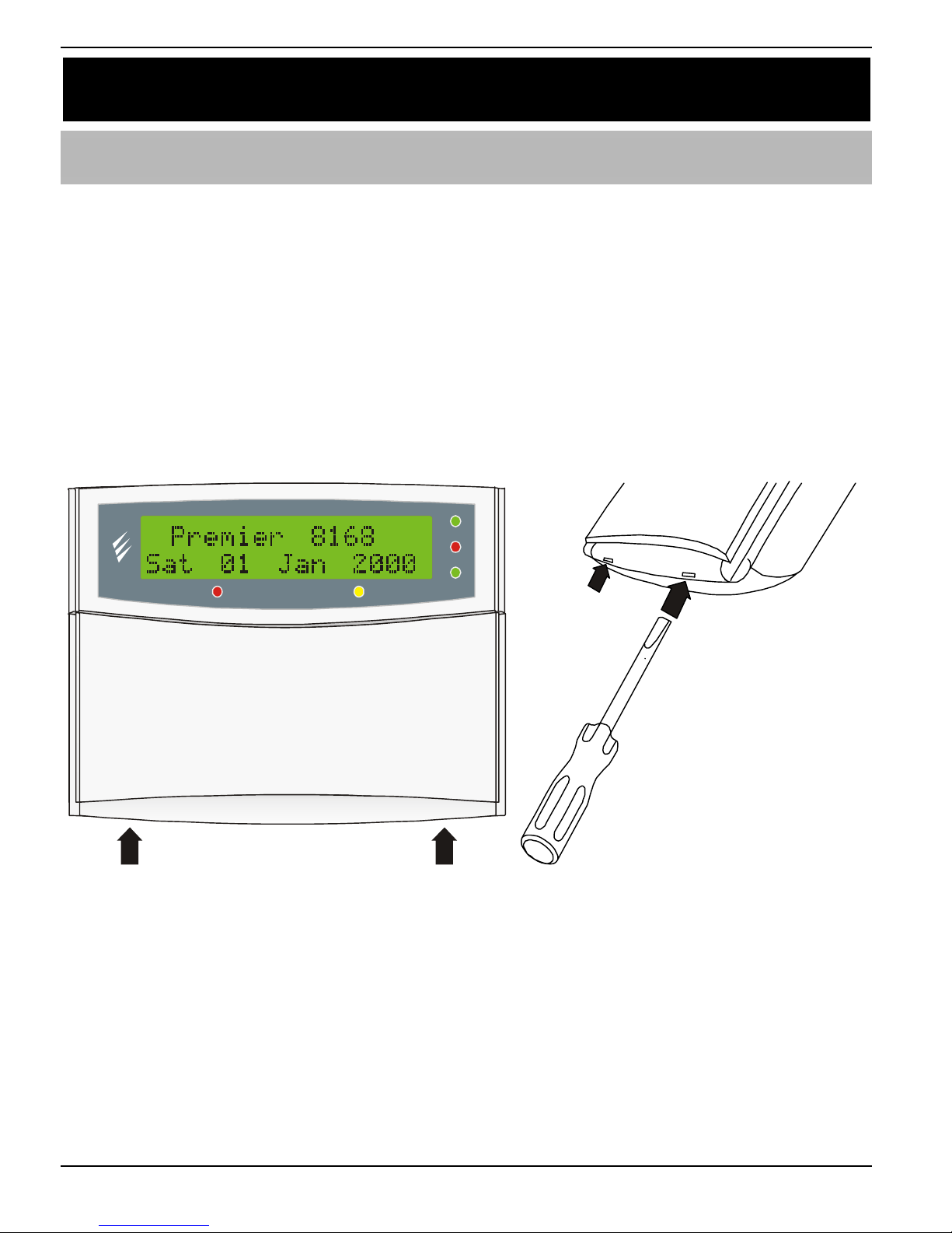
Open the keypad by carefully inserting a small flat-blade screwdriver into each slot
at the base of the unit. Gently push the screwdriver to ease the retaining clips
upward, DO NOT LEVER OR TWIST. Excessive force is NOT required. The front
flap and front cover can now be removed.
Mount the keypad using at least two appropriate countersunk screws (no larger
than No. 8). A keyhole slot has been provided to assist mounting and aid levelling.
Power
Info.
Ready
Servi ceOmit
Page 7
Premier LCD & LCDL Installation Manual Installation
INS180 7
Connecting Keypads
Before connecting keypads, isolate ALL power from the control panel (AC Mains
and Battery). Do not continue if there is power still present on the control panel.
! "
Connecting a keypad with power still present on the control panel may
damage the keypad or control panel and invalidate any warranty.
Keypads, zone expanders and output modules are all connected to the same network
terminals located at the bottom left hand corner of the control panel and may be
connected serially (daisy chain), in parallel (star) or any combination of the two.
! "
A maximum of 8 zone expanders, 8 keypads and 4 output modules can be
connected to each network.
Whenever new devices are connected to the network, they must be
confirmed onto the system using the ‘Check Networks’ menu option. For
details on confirming devices please refer to the Premier 888/8168
Installation Manual.
Wiring the Network
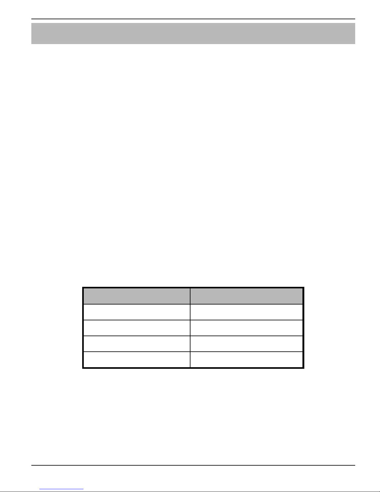
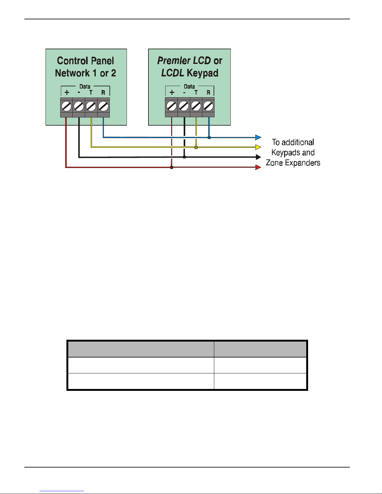
The networks are made up of four terminals incorporating power and data. To
ensure correct operation, all four terminals on the device must be connected to the
corresponding terminals on the control panel or previous device. The table below
shows each terminal and its description:
Terminal Description
+ +12V Supply
- 0V Supply
T Transmit Data
R Receive Data
Keypads can be connected using 4-core cable. However, it is recommended that 6
or 8-core cable is used as the spare cores can be used to ‘Double Up’ on the
power connections if needed.
! "
Standard 7/0.2 alarm cable can be used for most installations. However,
under certain conditions it may be necessary to use screened cable.
Page 8
Installation Premier LCD & LCDL Installation Manual
8 INS180
Network Connections
Cable Distances
The maximum recommended distance for keypads when using standard 7/0.2
alarm cable is:
• 250m for each branch when using the star (parallel) configuration
• When using a daisy chain (series) configuration the maximum distance will
depend on the number of devices connected on the chain. The more devices
that are connected, the shorter the distance to the last device (this is due to
voltage drop in the cable)
Whichever method of wiring configuration is used, ensure that the voltage between
the ‘+’ and ‘–’ terminals at each device is no lower than 10.0V when the system is
running on the standby battery. The table below shows maximum cable runs when
one keypad is installed using standard 7/0.2 alarm cable:
Configuration Max. Cable Run
1. Keypad + 2 PIR’s @15mA 250m
2. As No. 1 + 16Ω Speaker
100m
Distances of up to 1km can be achieved between the control panel and a keypad.
However, a power supply must be installed close to the keypad to power it locally,
this will help to overcome voltage drop caused by the long cable run.
Page 9
Premier LCD & LCDL Installation Manual Installation
INS180 9
Overcoming Voltage Drop
There are several ways to overcome voltage drop:
• Use thicker lower resistance cable. Standard 7/0.2 alarm cable has a
resistance of 8Ω per 100m
• Double up on the power connections – this will require using a 6 or 8-core
cable rather than a 4-core cable
• Install a power supply to power the device locally, remember to common the
two negative connections
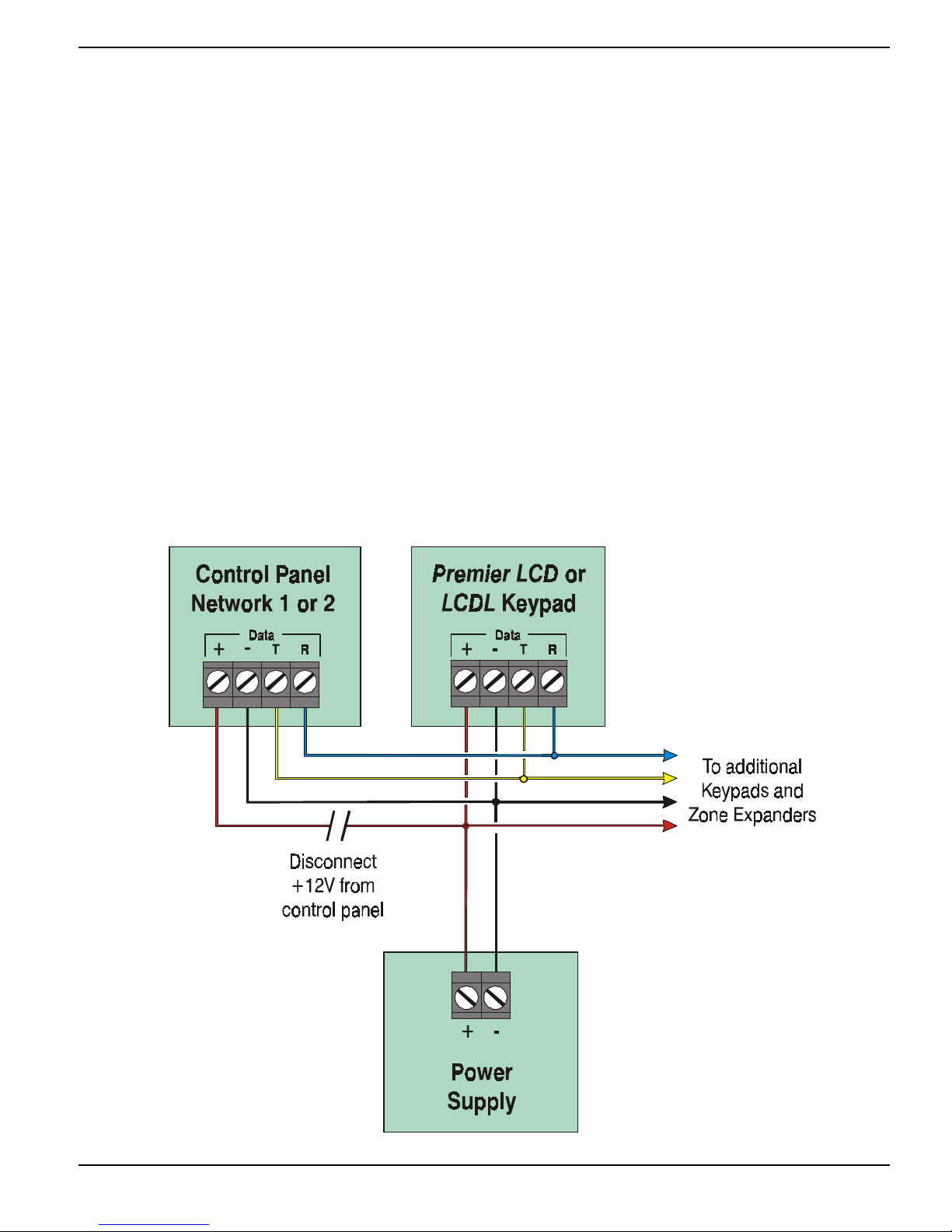
Installing a Power Supply
One way to overcome voltage drop at a keypad is to install a power supply nearby to
power the keypad locally. When a power supply is installed, the 0V connection on the
power supply must be connected through to 0V on the control panel and the +12V
connection between the control panel and the keypad must be disconnected.
Page 10

Installation Premier LCD & LCDL Installation Manual
10 INS180
Selecting an Address
Each keypad must be assigned a different address using the DIL switches located
on the left hand side of the PCB. The table below shows the keypad addressing:
Address DIL 1 DIL 2 DIL 3 DIL 4
1 On/Off Off Off Off
2 Off On Off Off
3 Off Off On Off
4 Off Off Off On
5 On Off Off On
6 Off On Off On
7 Off Off On On
8 On Off On On
Engineers On On On On
! "
Never set two keypads on the same network to the same address.
Keypads are factory set to address 1.
Page 11
Premier LCD & LCDL Installation Manual Installation
INS180 11
Wiring Zones to the Keypad
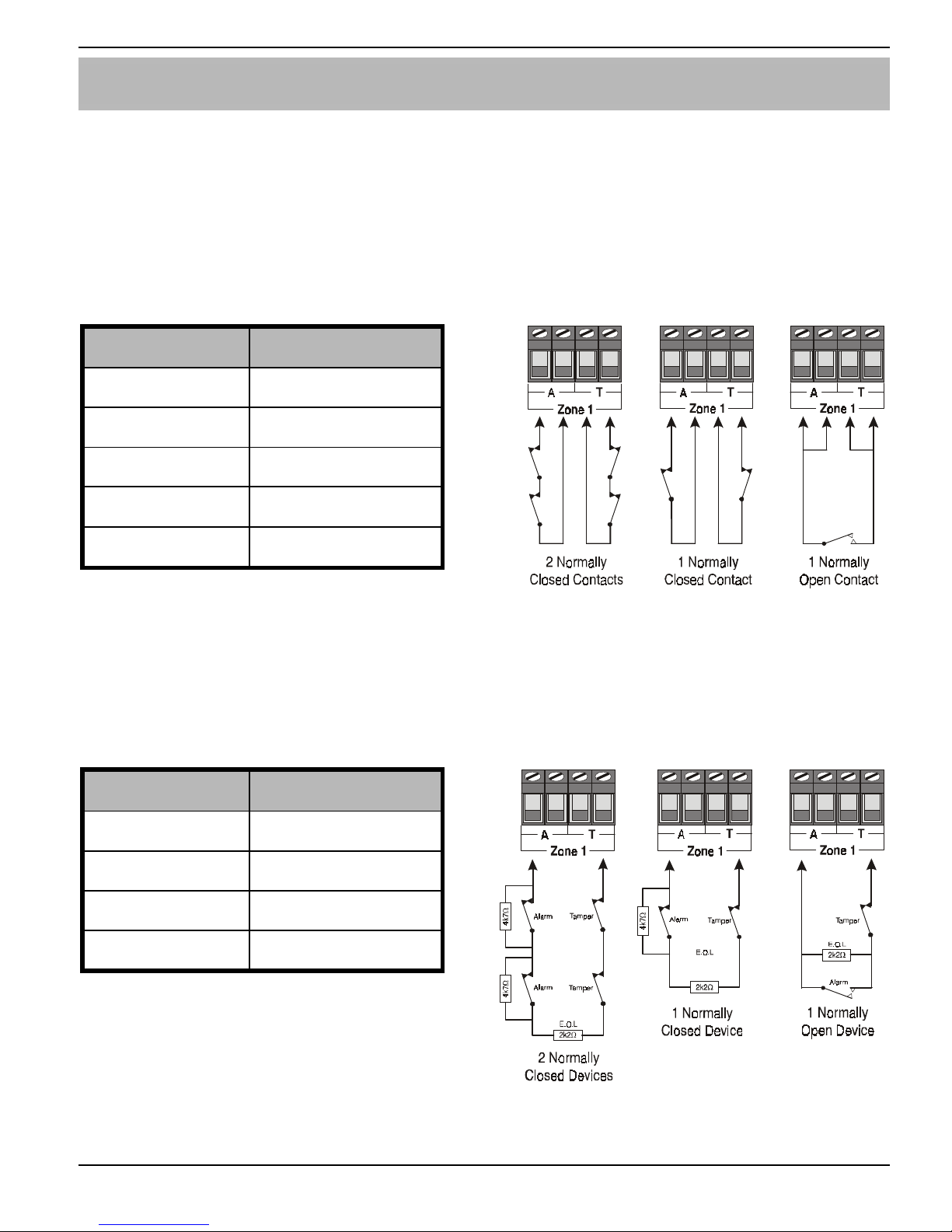
The keypad has 2 fully programmable zones, ensure that no more than 5 detectors
are connected to each zone. Please refer to the Premier 888/8168 Installation
Manual for programming details.
Double Pole
Use this wiring configuration when connecting normally closed or normally open
detection devices to the zone using 4-Wires, the system will respond as follows:
Zone Status Response
‘A’ Closed Zone Secure
‘A’ Open Zone Active
‘T’ Closed Tamper Secure
‘T’ Open Tamper Active
Short Circuit Zone Tamper *
* Can be programmed for ‘Active’
or ‘Tamper’ response.
End Of Line
Use this wiring configuration when connecting normally closed or normally open
detection devices to the zone using 2-Wires, the system will respond as follows:
Zone Status Response
Short Circuit Zone Tamper *
2k2 (EOL) Zone Secure
6k5 - 30k Zone Active
Open Circuit Zone Tamper
* Can be programmed for ‘Active’
or ‘Tamper’ response.
Once the zones have been programmed, they should be tested to ensure correct
operation (see page 13 for details).
Page 12
Installation Premier LCD & LCDL Installation Manual
12 INS180
Connecting Speakers to the Keypad
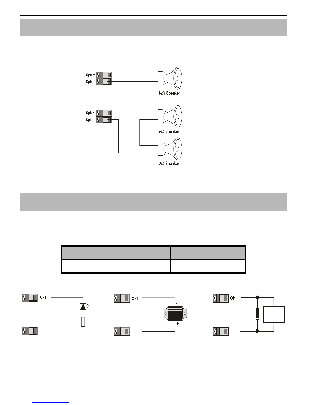
The Premier LCDL has an output on it that can be used to drive loudspeakers. The
output is capable of driving up to one 16Ω or two 8Ω loudspeakers as shown below:
The speakers should be tested to ensure correct operation (see page 13 for details).
Connecting the Keypad Output
Both keypads have 1 fully programmable output. This output can be used to drive
auxiliary devices such as LED’s, sounders or relays etc. The table below shows the
electrical characteristics for the output:
No Max Current Type
1 100mA Switched -ve
The diagram below shows typical wiring examples for the outputs:
For details on programming outputs, please refer to the Premier 888/8168
Installation Manual. Once the outputs have been programmed, they should also be
tested to ensure correct operation (see page 13 for details).
1K0
LED
+12V
12V Buzzer
+12V
Diode
(IN4148)
Relay
+12V
Page 13

LCD & LCD-Pro Installation Manual Installation
INS180 13
Other Features
Programmable ‘Info.’ LED
The ‘Info.’ LED on the front of the keypad can be programmed to mimic the keypad
output or show the armed status of an area. For details on programming the ‘Info.’
LED, please refer to the Premier 888/8168 Installation Manual.
Adjustable Backlighting
To adjust the keypad backlighting press the YES key for 5 seconds, then with the
YES key still pressed use the SCROLL key to increase or decrease the
backlighting until the required brightness is achieved, then release both keys.
! "
The backlight can only be adjusted when the keypad is not in a menu.
Testing the Keypad
Whenever new devices are connected to the networks, they must be confirmed
onto the system using the ‘Check Networks’ menu option. For details on confirming
devices, please refer to the Premier 888/8168 Installation Manual.
Testing the zones
The zones on the keypad can be individually tested to ensure correct operation,
this can be done by either using the ‘Walk Test’ menu option or the ‘View Zone
Status’ menu option. For details on walk testing or viewing zones, please refer to
the Premier 888/8168 Installation Manual.
Testing the Output
The output on the keypad can be tested to ensure correct operation, this can be
done using the ‘Output Test’ menu option. For details on testing outputs, please
refer to the Premier 888/8168 Installation Manual.
Testing the Speaker (Premier LCDL only)
The speaker output on the keypad can be tested to ensure correct operation, this
can be done using the ‘Output Test’ menu option. For details on testing outputs,
please refer to the Premier 888/8168 Installation Manual.
The speaker volume for the keypad is also fully adjustable. For details on adjusting
the speaker volume please refer to the Premier 888/8168 Installation Manual.
Page 14

Specifications Premier LCD & LCDL Installation Manual
14 INS180
3. Specifications
Electrical
Operating Voltage 10 - 13.7VDC
Current Consumption
Quiescent
In Alarm
35mA
85mA
Network
4-wire standard 7/0.2 alarm cable up to
250m. Star, Daisy Chain or any
combination of the two
Keypad Type
Premier LCD
Premier LCDL
32 Character LCD Display
32 Character Large LCD Display
Zones
Number
EOL Resistor Value
2
2k2 EOL & 4k7 Contact
Output
O/P 1
100mA switched to 0V
Back Lighting Fully Adjustable
Speaker Output (LCDL Only)
Minimum Load 8Ω
Speaker Volume (LCDL Only)
Fully Programmable Volume Levels
Environmental
Operating Temperature
-10°C (+14°F) to +50°C (+122°F)
Storage Temperature
-20°C (-4°F) to +60°C (+140°F)
Maximum Humidity 95% non-condensing
EMC Environment Residential
Commercial
Light Industrial
Industrial
Page 15

LCD & LCD-Pro Installation Manual Specifications
INS180 15
Physical
Dimensions 145mm x 115mm x 30mm
Packed Weight 260g approx.
Standards
Conforms to European Union (EU) Electro-Magnetic Compatibility (EMC) Directive
89/336/EEC (amended by 92/31/EEC and 93/68/EEC).
The CE mark indicates that this product complies with the European requirements
for safety, health, environmental and customer protection.
Warranty
All Texecom products are designed for reliable, trouble-free operation. Quality is
carefully monitored by extensive computerised testing. As a result the Premier LCD
and LCDL keypads are covered by a two-year warranty against defects in material
or workmanship.
As the Premier LCD and LCDL keypads are not a complete alarm system but only a
part thereof, Texecom cannot accept responsibility or liability for any damages
whatsoever based on a claim that the Premier LCD or LCDL failed to function
correctly.
Due to our policy of continuous improvement Texecom reserve the right to change
specification without prior notice.
Premier is a trademark of Texecom Ltd.
Page 16

INS180
Texecom Limited, Bradwood Court, St. Crispin Way, Haslingden, Lancashire
BB4 4PW, England.
Technical Support:
Tel: +44 (0)1706 234833
Tel: +44 (0)1706 234811
Fax: +44 (0)1706 213187
 Loading...