

Page 1
Installation Manual
Premier Elite ComIP
INS273-6
Product Type - CEJ0000
Page 2
Premier Elite ComIP Installation Manual
2 INS273-6
1. Overview
Introduction
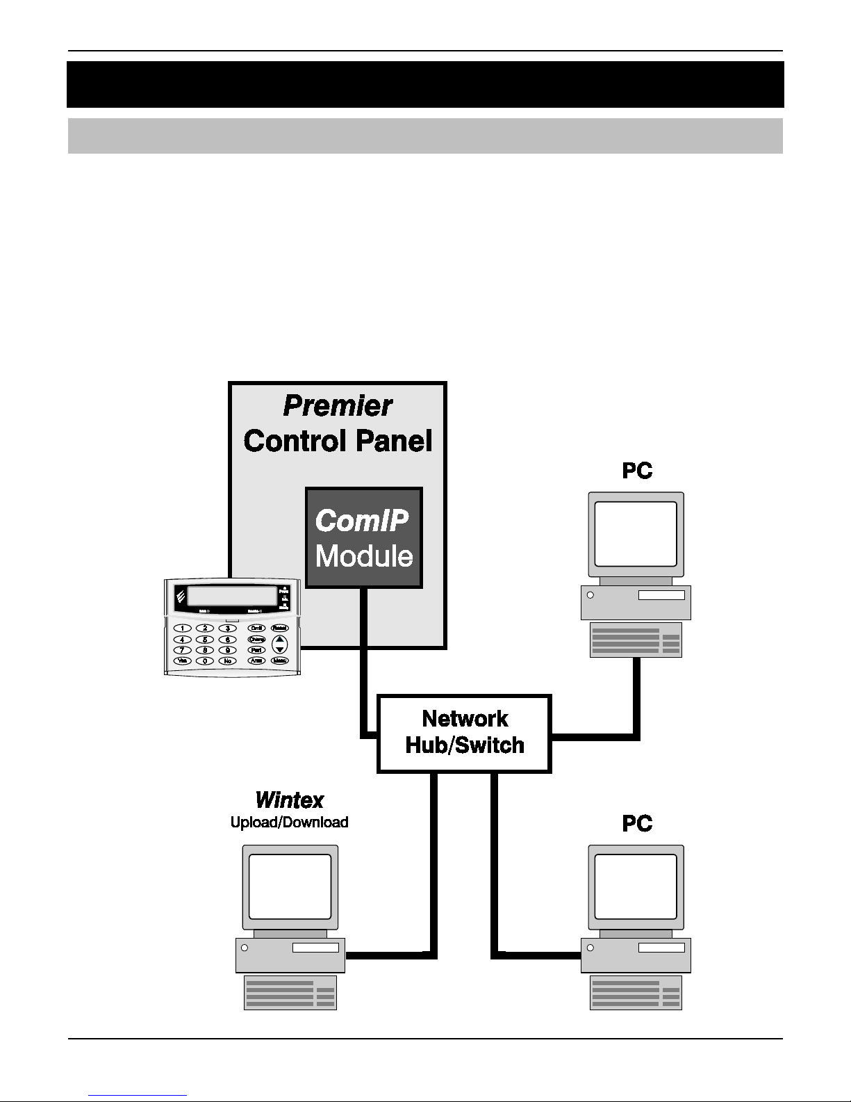
The ComIP module allows the Premier & Premier Elite control panels to be connected to either a
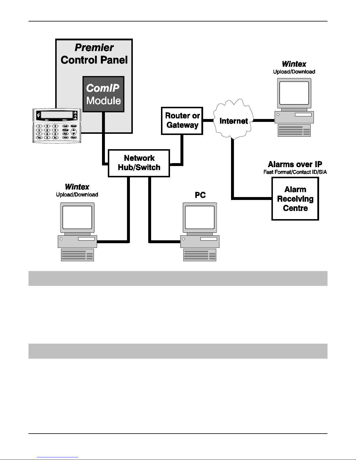
Local Area Network (LAN) or Wide Area Network (WAN). The internet is considered to be a WAN.
Once the control panel is connected to a network the following functions can be achieved:
• Upload/Download via Wintex UDL
• Receive Push Notifications, Arm, Disarm, Part Arm & Reset via Texecom mobile app's
• Signal alarms to an Alarm Receiving Centre
• High security polling by Alarm Receiving Centre
Typical LAN configuration
Page 3
Premier Elite ComIP Installation Manual
INS273-6 3
Typical WAN configuration
Supported Control Panels
The ComIP module is supported on the following Premier & Elite Series control panels, this manual
assumes use with Premier Elite panels:
• Premier 412/816 816 Plus & 832
• Premier Elite 12/24/48/88/168 & 640
• Premier 48/88/168 & 640 V7 or later
General
The installation of the ComIP module requires a basic understanding of networking and TCP/IP
protocol. If you are not familiar with these concepts, you may require assistance from an IT
professional before attempting to install the module.
The ComIP module is designed to be fitted inside the control panel and is powered via the harness
connection supplied.
Page 4
Premier Elite ComIP Installation Manual
4 INS273-6
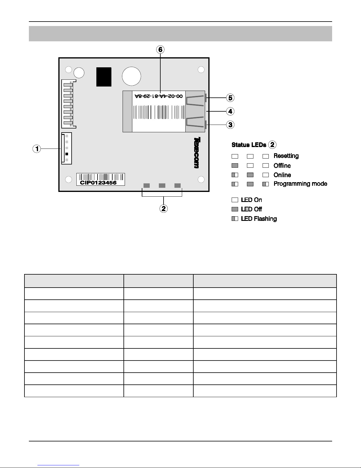
PCB Layout
5-way harness connection to control panel
ComIP Status LEDs
Network status LED (Left)
Network status LED (Right)
RJ45 network Connection
MAC address
Left LED Right LED Meaning
Off Off No Link
Off Solid Amber 100BASE-T Half Duplex Link
Off Blinking Amber 100BASE-T Half Duplex; Activity
Off Solid Green 100BASE-T Full Duplex Link
Off Blinking Green 100BASE-T Full Duplex; Activity
Solid Amber Off 10BASE-T Half Duplex Link
Blinking Amber Off 10BASE-T Half Duplex; Activity
Solid Green Off 10BASE-T Full Duplex Link
Blinking Green Off 10BASE-T Full Duplex; Activity
Page 5

Premier Elite ComIP Installation Manual
INS273-6 5
Installation
Introduction
This step by step guide will allow you to achieve the following and should be carried out in the order
detailed in the manual.
• Installation
• Assign an IP address manually
o Reserve the IP address
o Set the DHCP Pool
• Setup port forwarding on the router
• Setup push notifications
• Programme the control panel
2. Assigning an IP address
Before proceeding you should ensure you can access the router as changes will need to be made to
ensure the ComIP will function as expected, and so that you can configure the router to allow
access from the outside world (WAN) should you require.
You will need to know the following; the default information should be available from the router
documentation:
• The IP address of the router
• The router name
• The router password
Before assigning an IP address it is important to understand how IP addresses work and the impact
this can have on the performance of the system and the ComIP.
IP Address Information
Each TCP/IP node on a network host has a unique IP address. This address provides the
information needed to forward packets on the local network and across multiple networks if
necessary.
IP addresses are specified as x.x.x.x, where each x is a number from 1 to 254; for example,
192.168.0.200. The ComIP must be assigned a unique IP address to use on a TCP/IP network. If the
address is left blank or is programmed as 0.0.0.0 the ComIP module will try to automatically obtain
an IP address from a DHCP server (if one is running on the network).
Port Numbers
The port number used to identify the channel for remote initiated connections. The default setting is
10001. The range for port settings is: 1-65535 except for the following reserved ports:
Port Numbers Reserved for
1-1024 Reserved (well known ports)
9999 Telnet setup
14000-14009 Reserved
30718 Reserved
10000 - 10999 Recommended for raw socket connections
Page 6
Premier Elite ComIP Installation Manual
6 INS273-6
Gateway
The gateway address, or router, allows communication to other LAN/WAN segments. The gateway
address should be the IP address of the router connected to the same LAN segment as the ComIP.
The gateway address must be within the local network.
Netmask (Subnet Mask)
A netmask defines the number of bits taken from the IP address that are assigned for the host
section. The default mask is 255.255.255.0 (8 bits).
Automatically Assigned IP Address (DHCP)
DHCP (Dynamic Host Configuration Protocol) is by far the most common method for routers to
assign devices IP addresses so that they can use connections to access the Internet and other
resources on the network.
IP addresses will be assigned, from a "pool" for a "lease" time, and can change from device day to
day;
If you allow the router to automatically assign an IP address to the ComIP you may encounter
problems with IP conflicts if:
• Another device on the network has ever used the address (and could do so again)
• The ComIP is off line and another device is given the address by the router.
To overcome these potential issues it is advised that the IP address is either reserved for the ComIP,
or the IP address used for the ComIP is outside of the DHCP Pool.
Accessing the Router
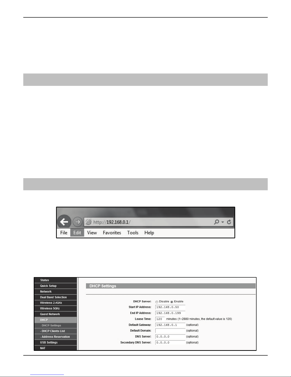
On the PC open the web browser and type the routers IP address into the address bar as shown
and press enter. Values used are typical only; they may be or may not the same as the router.
When prompted enter the router user name & password and press Enter.
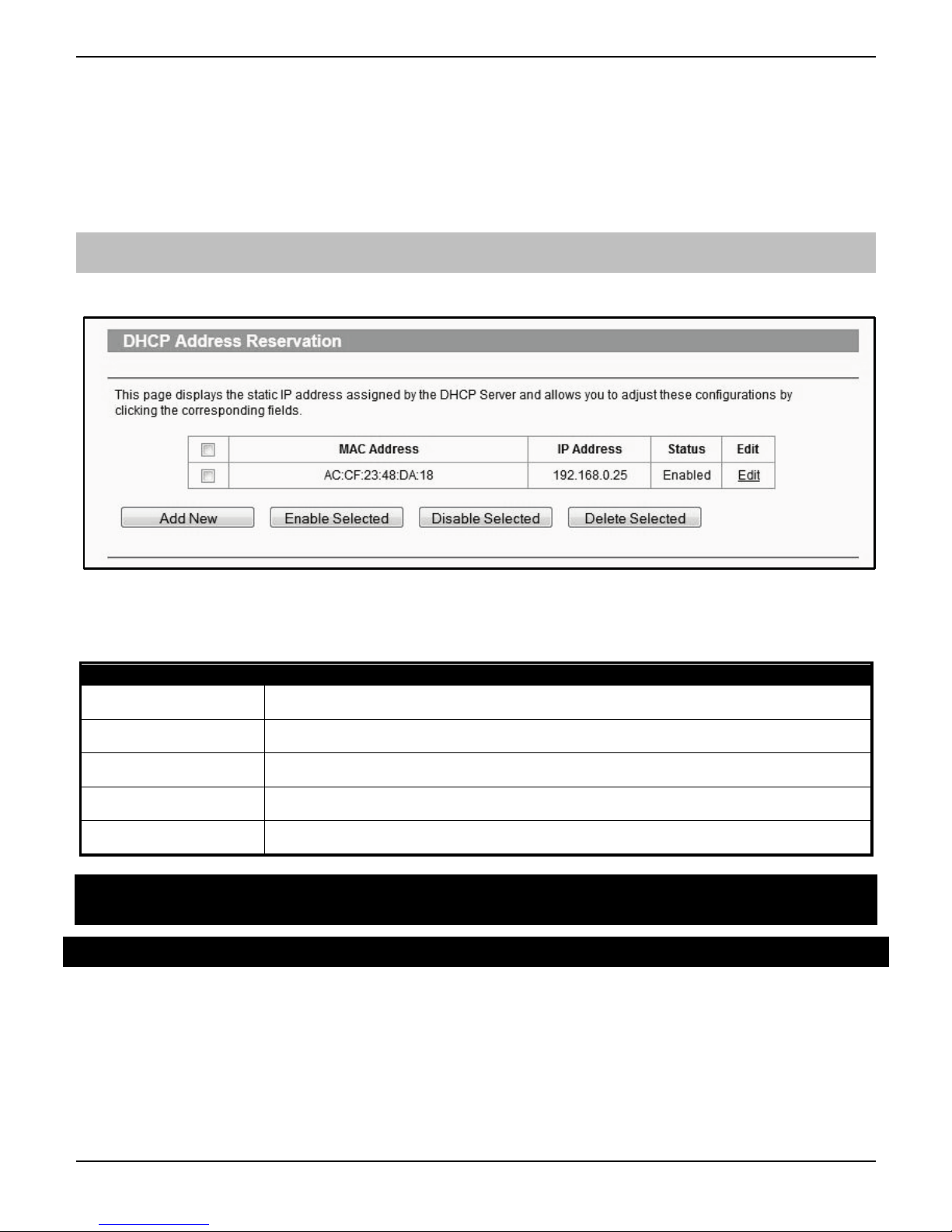
Once you have access to the router you are looking for DHCP Settings, the example shown may or
may not be the same as the router. You will see a Start & End IP address, this is the DHCP pool or
the range of addresses used by the router when assigning an address automatically.
Page 7
Premier Elite ComIP Installation Manual
INS273-6 7
You now know the address range being used by the router. The Default Gateway is the actual router
itself.
So you can now decide how you want to configure the ComIP.
• If assigning an address within the DHCP pool you should reserve the IP address for the
ComIP.
• If assigning an address outside of the DHCP pool, there is no need to reserve the address.
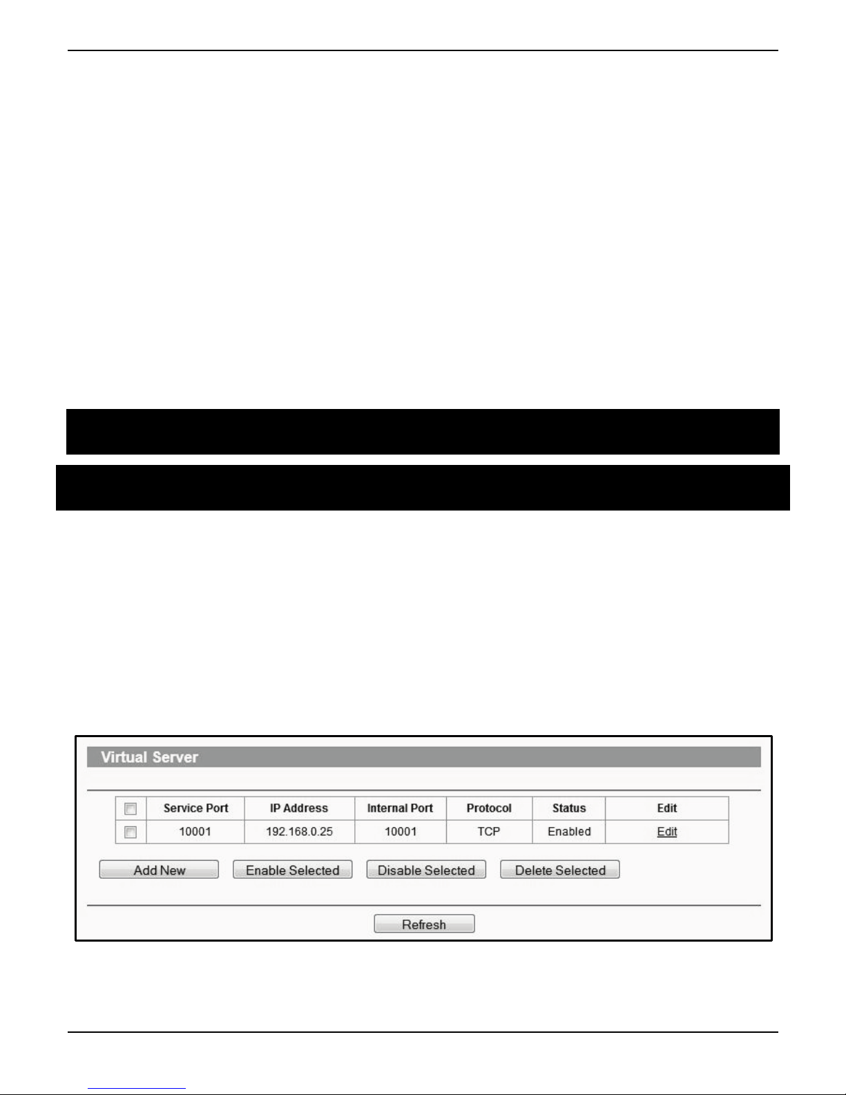
DHCP Reservation
On the PC check for DHCP or Address reservation. You should have something like this.
Click Add New or whatever the router displays and enter the required details. The MAC address is
printed on the ComIP and will be required, as will the IP address you will be assigning to the
ComIP. Once you have entered the details press Save.
Record the details here
IP Address
Subnet Mask
Gateway
DNS
MAC Address
3. Premier Elite 12/24/48/88/168 & 640
Please refer to the relevant Control Panel installation manual for all other models.
Now the ComIP is enabled on the network, the Control Panel needs to be configured to allow
communication.
• Enter Engineer mode on the keypad.
• Press then / (UDL/Digi Options).
• Press then / for (Setup Modules).
• Press then / for (Setup IP data).
Page 8
Premier Elite ComIP Installation Manual
8 INS273-6
• Press / and enter the IP address of the ComIP you noted in the previous steps.
Pressing / when complete. Pressing the / key twice will enter a dot. For
Example 192.168.0.150
• Scroll down once to change the port number. This is required if you wish to setup port
forwarding through the router. The port can be left as 10001.
• Scroll down and enter the Gateway address assigned to the ComIP.
• Scroll down once and enter the subnet mask assigned to the ComIP
• Press / twice.
• Press then / (Comport Setup).
• Scroll to the comport you have the ComIP plugged onto.
• Press / and / for ComIP module.
The settings will be sent to the ComIP. After a minute the unit will be ready to use.
Exit Engineers mode on the control panel.
The control panel can now be accessed on the LAN. However, to access the panel from the
Texecom mobile apps or Wintex remotely, additional steps are required within the various
programmes and the control panel.
4. Port Forwarding
WARNING: Care should be taken when opening ports as this can leave the router vulnerable to
malicious attacks.
To allow the system to communicate with the outside world, and vice versa, port forwarding must be
enabled on the router for the ComIP. The below example is typical, however please check you
routers documentation or the manufacturers website for more information. This will be required in
order to use the app remotely.
To setup Port Forwarding do the following.
• Connect to the Router
• Look for settings for "Forwarding”, or "Port Forwarding" these could be under advanced
settings, or in the Firewall settings. Each manufacturer is different.
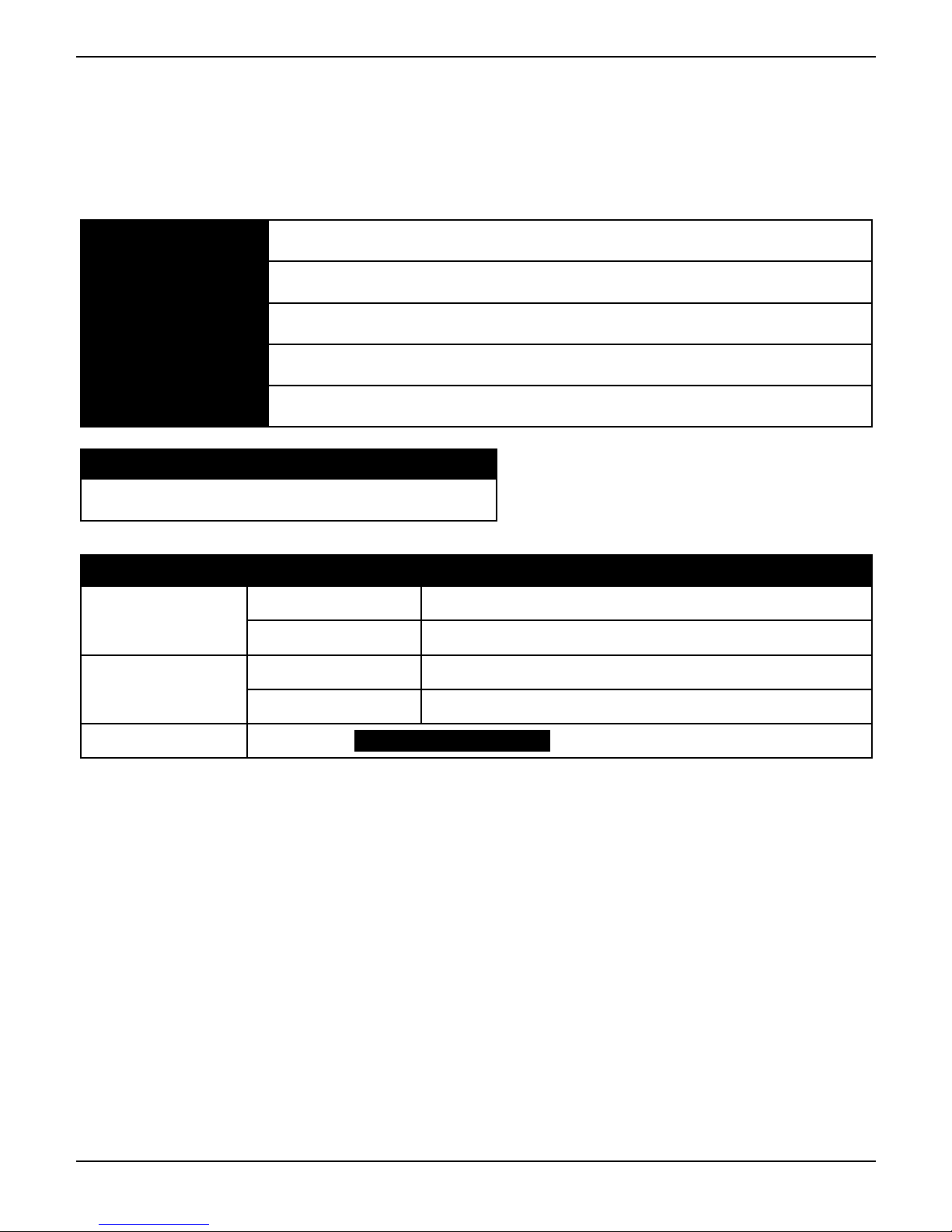
Once you have found the option you will have something like this.
• Add a new rule using the ComIP IP address and Port Number you used earlier.
Page 9

Premier Elite ComIP Installation Manual
INS273-6 9
Some routers may require use of the MAC address to allow port forwarding. Please
check with the manufacturer’s documentation or website for details.
5. Wintex setup
Local Connections (LAN)
In Wintex do the following:-
• Click New
• On the Customer Details page enter an Account Reference
• On the Panel Details page
o Choose the Panel Type & Software Version.
o Ensure the UDL Password matches what is in the panel.
o Enter the IP Address of the ComIP into the Host Address field
o Enter the port number from the panel into the Host Port field.
• click ADD
You have now configured Wintex for a local connection to the control panel. To access the panel do
the following:
• In Wintex click on Connect
• Scroll down and choose Click via Network (192.168.0.100 on port 10001)
• Once connected the status (bottom left of the Wintex screen) will change to Online Ready.
Remote Connections (WAN)
Before attempting to connect to the system from a remote location, please read the section on Port
Forwarding, this will need to be done to allow access from outside of the LAN.
Fixed IP address (Uncommon)
If you have a fixed IP address internet connection, complete all of the details above, BUT replace the
Host Address with the Fixed IP address provided by the Internet Service Provider.
Dynamic IP Address (most common)
It is most likely that you have a Dynamic IP address assigned by the service provider. This basically
allows the Local system to connect to the outside world (Internet WAN), and can change frequently.
Because of the nature of Dynamic addresses you will need a third party service to manage the IP
address to ensure you can always connect to the system.
You should search for a Dynamic DNS service provider, who may or may not charge a fee for the
service. Once you have the service the Host Address will be replaced by the details given to you by
the DDNS provider. Without this service Wintex will not work remotely.
6. Texecom mobile app's
Texecom mobile apps can be used to access the system either remotely or locally. The apps are
supported on iOS & Android devices and can be downloaded from the respective app stores. All
three apps are configured identically for access.
Detailed information regarding all of the app settings can be found in the Help file and instructions
provided with the app. The following sections only deal with the connection setup, and enabling
Page 10

Premier Elite ComIP Installation Manual
10 INS273-6
Push Notifications. The app instructions also include a pictorial guide and can be found in the App
under Settings>Help
Local Connection
Once the app is installed do the following:
• Click to Open
• Login the default User Name and Password are Master & 123456 respectively.
• You will be asked if you want to use the New Layout, choose yes
• Choose My Sites
o A warning box will appear saying you have No Site Settings, take note of the
instruction and press OK
• Swipe Left (iOS) or hold (Android) on the Site Name and choose Edit
• Click on Site Name and enter a Site Name & Site Summary
• Click Back and then IP Details, enter the IP address and Host Port of the ComIP from the
previous steps in these instructions.
o Update IP should be enabled if you want to setup Push Notifications.
o Stay Connected stops the app disconnecting from the control panel when
swiping between screens.
• Click Back then Security Details, enter the UDL Password from the Control Panel. This
cannot be left blank and must match the Control Panel UDL password. For details on
Protected UDL Password please see the app Instruction Manual.
• Click Back and then User Areas, Enter the User Code that you use with the Control Panel
and the User Number. The User Number will be for example 1, do not type User 1.
The app is now set up for Local (LAN) connections.
Remote connection & Push Notifications
For remote connections it is highly recommended that you enable Push Notifications. This will mean
that Texecom will track the IP address and update it as required. If the service provider does not
provide you with a fixed IP address (most don't) you will require a third party DDNS provider to allow
the app to operate remotely if you do not "Enable" push notifications.
Port Forwarding must be setup on the router to allow remote connections. Please see
Page 8
Follow the instructions given above for Local Connections and then do the following:
• Click on My Sites then enter Edit mode for the chosen site.
• Click on Notifications. You must press Yes and accept the disclaimer before you can
proceed.
• Choose & enter a User Name
• Choose & enter a Password
• Enter a valid Email Address (Notifications will not be setup without a valid address)
• Leave the Account Number field blank.
• Click Register Account
You will receive an email with a Verification Code, follow the instructions in the email. Enter the
Verification Code you are given into the Account Number box and press Register. Once you have
completed this step the Account Number will be automatically populated with an Account Number
Page 11
Premier Elite ComIP Installation Manual
INS273-6 11
allocated by the Server. Record all of the details here for future use, and if you choose to add an
additional device to receive notifications from the same site.
Setting up additional devices to receive notifications from the same site requires that ALL details are
Identical all devices. This includes the Site Name & Site Summary. To register an additional device
complete all details for the Site. On the Registration page complete all details including the Account
Number you now have and press Register.
Site Name
Site Summary
User Name
Password
Email Address
Push Notification Account Number
Texecom App Server Information
Primary IP Address 54.88.92.200
Port Number 10001
Secondary IP Address 52.28.12.230
Port Number 10001
Polling Time 15 Minutes Poll Timer MUST be set
ARC Settings & Reporting Options
• Enter the Engineers Code
• Press / (UDL/Digi Options)then (Program Digi) /
• Using the Scroll key select Which ARC you wish to use
• Press / and scroll to change the ARC protocol to either SIAII or Contact ID, both are
supported.
• Press / twice then /
• In the Pri. Tel No: screen enter the Push Notification Sever Address exactly like this:
54.88.92.200/10001 To enter the dot press the / key twice. To enter the / press the
/ key twice
o 54.88.92.200/10001
• Press /
• In the Sec. Tel No: screen enter the Push Notification Sever Address exactly like this:
52.28.12.230/10001 To enter the dot press the / key twice. To enter the / press the
/ key twice
o 52.28.12.230/10001
• Press /
Page 12

Premier Elite ComIP Installation Manual
12 INS273-6
• Press / and then enter the six digit XXXXXX Account Number you were given in the
app
• Press / then / (Dial Attempts) enter a minimum of 2
• Press / twice
• Press / and edit the Areas you wish to receive notifications for.
• Press / then / and toggle the reporting options on or off, depending on what
you want to receive notifications of. Use the / button to toggle each option on or off.
• Press / then / and scroll across the screen and use the / button to
toggle option 7 Connect Via IP ON (an I will be shown on the screen)
• If you chose SIAII as the Protocol in previous steps scroll once more to Option 8 and toggle
Send SIA Text to ON (a T will be shown).
• Press /
DO NOT EXIT ENGINEERS MODE YOU MUST SETUP POLLING FOR THE SYSTEM TO WORK
CORRECTLY.
Control Panel Setup for Polling
To setup the Control Panel for Polling do the following:
• Press / twice
• Press then / twice (Global Options/System Timers)
• Scroll to Poll IP Every
• Press / and then enter a value 15 minutes (015).
The polling time is controlled by the server and may be changed.
Enable Digi, Dial All Numbers & Test Call
To test the settings, initialize a Push Notification and update the IP address in the app a test call
should be carried out. Please ensure the Digi is Enabled, Dial All Numbers is enabled for systems
with multiple communication devices installed.
Digi Enabled & Dial All Numbers
If you have more than one communication device connected to the control panel, Dial All Numbers
MUST be enabled; continuing from the previous steps:
• Press / then (Digi Options)
• Press / then / scroll through the options and ensure Digi is Enabled (E shown
on Screen) and Dial All Numbers (A shown on screen)are on, Use the / button to
toggle each option on or off.
• Press /
Initialise a Test Call
• Press / then / (Start Test Call)
• Press to start the test call. All communication devices on the system will carry out a test
call.
Once completed and if successful you will receive a notification from the Control Panel to the app.
Do not exit Engineers mode yet. Please read below:
Optional Additional Panel Settings
Due to the nature of routers and services provided by the ISP, devices of all types can just "drop off"
a network, certain circumstance may cause an ATS Failure to be displayed to the end user. The
Page 13

Premier Elite ComIP Installation Manual
INS273-6 13
panel will automatically recover itself once the network is available. However to avoid this potential
inconvenience please see below.
EN50131 System
With an EN50131 installed system, the warning about an ATS Failure will only be visible to the User
when they enter their code and the fault is still present. In the case of this type of system the
chances of a User actually seeing the fault will be minimal. It is also a requirement of systems with
additional communication devices that signal to an ARC or other response authority to report these
faults.
Non-EN50131 System
If the system is installed and configured to NOT comply with EN50131 and has no additional
communication devices signaling to an ARC or response authority, then an ATS failure will be
displayed immediately on the keypad at the time the fault occurs. Again no action is actually
required by the user as the panel will recover of its own accord. However if the Users WiFi
connection has a tendency to drop devices, this could be a source of frustration. Two options are
available as detailed below.
Setting an ATS Fault delay
• Enter Engineers Mode
• Press then / (Global Options)
• Press / (System Timers)
• Use and scroll to ATS Fault Delay
• Press / , then enter 002 to set a two minute delay
• Press /
• Exit Engineers Mode
Disabling ATS failed messages
To stop the keypad displaying the ATS Failed message in this scenario do the following;
• Enter Engineers Mode
• Press then / (Global Options) Press then / again (Monitor
Hardware)
• Press / Press / again to toggle ATS Path Faults OFF Press /
• Exit Engineers Mode
If the ComIP misses its polling in a 1 hour time window, the server will send notification
directly to the app.
Do NOT do this on an EN50131 system, or on a system that has additional
communication that signals to an ARC or other response authority.
Checking IP Updates
Now do the following to confirm that the setup is correct.
• Login to the app
• Connect To Site, you should now be online with the system
• Go back to My Sites
• Go to Edit Site and click IP Details
Page 14

Premier Elite ComIP Installation Manual
14 INS273-6
• The IP address will have changed. The address now being shown is provided by the ISP and
will match the WAN IP address shown in the router.
If for some reason this has not worked please see details below to troubleshoot the installation.
7. Disclaimer
Operation
Texecom cannot guarantee the operation of the network or the Internet Service Provider (ISP), and
as such make no claims for reliability of connections or system performance.
Push Notifications
Push notifications are used entirely at the users own risk and Texecom will accept no liability for
system failure, missed communications, failure of polling, failure of message delivery or any other
failing which may occur.
Public, Shared, Corporate & Company Network Use
Many public, shared, corporate and company networks will block access to ports both incoming
and outgoing. Texecom cannot guarantee that use of such wired or wireless networks will allow
access to the alarm system, or indeed receipt of push notifications. If you cannot access the system
or receive notifications on a particular network, you should switch the devices WiFi off and use the
3G or GPRS network, or consult the network owners.
Technical Support
Texecom Technical Support should not be expected to assist installers or end users with
configurations of network components, other than the ComIP itself. It is the installer or users
responsibility to be able to provide the information required to enable the device, and to make
configuration changes to routers and switches where required.
8. Troubleshooting
Q: I cannot connect to the ComIP using Wintex or the app.
A: Change the comport that the ComIP is connected to Nothing Fitted on the Panel and press Yes.
Then change this back to Com-IP. This will resend the settings to the unit.
Q: I can connect locally but not remotely
A: For the app have you registered for push notifications? For Wintex have you registered with a
DDNS provider? Check that port forwarding is setup correctly for the router.
Q: My Router does not support port forwarding for fixed IP addresses outside the DHCP pool
A: Assign an IP address from within the DHCP pool and reserve it using the MAC address.
Q: I have a Premier 412/816 or 832, how do I enter the IP address?
A: The IP address should be entered without dots. For example 1921680110001 instead of
192.168.0.1/10001
Page 15
Premier Elite ComIP Installation Manual
INS273-6 15
Specifications
Supply Voltage: 10 - 14VDC
Current Consumption: 210mA
Dimensions: 63mm x 55mm x 15mm
Packed Weight: 60g (Approximately)
Standards
Texecom declares that this product complies with the requirements of the
following directives:
• 2004/108/EC EMC Directive
• 2006/95/EC LVD Directive
• 2011/65/EU RoHS Directive
The product therefore meets all the requirements to enable it to be CE
marked.
Weee Directive: 2012/19/EU (WEEE directive): Products marked with this
symbol cannot be disposed of as unsorted municipal waste in the
European Union. For proper recycling, return this product to your local
supplier upon the purchase of equivalent new equipment, or dispose of it
at designated collec
tion points. For more information see:
www.recyclethis.info.
This product is a Type B Moveable device and is suitable for use in systems designed to
comply with EN 50131-1, EN50131-3 and PD6662 at Grade 2 and Environmental Class II.
ComIP complies with the requirements of EN50136-2-3, EN50136-1-1 and is suitable for use
in systems designed for use with ATS level 2 and environmental class 1 or 2.
Warranty
All Texecom products are designed for reliable, trouble-free operation. Quality is carefully monitored by
extensive computerised testing. As a result the ComIP is covered by a two-year warranty against defects
in material or workmanship.
Page 16

Texecom Limited, Bradwood Court, St. Crispin Way, Haslingden,
Lancashire BB4 4PW, England.
Technical Support:
UK Customers Tel: 08456 300 600
(Calls charged at 3.36 pence per minute from a BT landline. Calls from
other networks may vary.)
International Customers Tel: +44 1706 233875
Email: [email protected]
© Texecom Limited 2015
INS273-6
 Loading...