

Page 1

XDS51x Emulator
Installation Guide
SPNU070C
February 2002
Printed on Recycled Paper
Page 2

IMPORTANT NOTICE
Texas Instruments Incorporated and its subsidiaries (TI) reserve the right to make corrections,
modifications, enhancements, improvements, and other changes to its products and services at
any time and to discontinue any product or service without notice. Customers should obtain the
latest relevant information before placing orders and should verify that such information is current
and complete. All products are sold subject to TI’s terms and conditions of sale supplied at the
time of order acknowledgment.
TI warrants performance of its hardware products to the specifications applicable at the time of
sale in accordance with TI’s standard warranty . Testing and other quality control techniques are
used to the extent TI deems necessary to support this warranty. Except where mandated by
government requirements, testing of all parameters of each product is not necessarily performed.
TI assumes no liability for applications assistance or customer product design. Customers are
responsible for their products and applications using TI components. To minimize the risks
associated with customer products and applications, customers should provide adequate design
and operating safeguards.
TI does not warrant or represent that any license, either express or implied, is granted under any
TI patent right, copyright, mask work right, or other TI intellectual property right relating to any
combination, machine, or process in which TI products or services are used. Information
published by TI regarding third party products or services does not constitute a license from TI
to use such products or services or a warranty or endorsement thereof. Use of such information
may require a license from a third party under the patents or other intellectual property of that third
party , or a license from TI under the patents or other intellectual property of TI.
Reproduction of information in TI data books or data sheets is permissible only if reproduction
is without alteration and is accompanied by all associated warranties, conditions, limitations, and
notices. Reproduction of this information with alteration is an unfair and deceptive business
practice. TI is not responsible or liable for such altered documentation.
Resale of TI products or services with statements different from or beyond the parameters stated
by TI for that product or service voids all express and any implied warranties for the associated
TI product or service and is an unfair and deceptive business practice. TI is not responsible or
liable for any such statements.
Mailing Address:
Texas Instruments
Post Office Box 655303
Dallas, Texas 75265
Copyright 2002, Texas Instruments Incorporated
Page 3

About This Manual
This manual describes how to install an XDS510t emulator controller and the
XDS511t emulator board.
There are several XDS510 emulator controllers for use with different computers. These emulator controllers are the XDS510 and XDS510PP for use with
PCs, and the XDS510WSt for use with a SP ARCstation or an HP workstation.
This manual includes a chapter for each of the controllers and one chapter for
the XDS51 1.
Notational Conventions
Preface
Read This First
In this manual, program listings, program examples, and interactive displays
are shown in a special typeface similar to a typewriter’s. Examples use
a bold version of the special typeface for emphasis; interactive displays
use a bold version of the special typeface to distinguish commands that
you enter from items that the system displays (such as prompts, command
output, error messages, etc.).
Here is a sample program listing:
0011 0005 0001 .field 1, 2
0012 0005 0003 .field 3, 4
0013 0005 0006 .field 6, 3
0014 0006 .even
Here is an example of a system prompt and a command that you might enter:
C: csr –a /user/ti/simuboard/utilities
iii
Page 4

Information About Cautions and Warnings
Information About Cautions and Warnings
This manual contains cautions and warnings.
This is an example of a caution statement.
A caution statement describes a situation that could potentially
damage your software or equipment.
This is an example of a warning statement.
A warning statement describes a situation that could potentially
cause harm to you
The information in a caution or a warning is provided for your protection.
Please read each caution and warning carefully.
.
iv
Page 5

Related Documentation From Texas Instruments
Related Documentation From Texas Instruments
The following books describe the C source debugger for the TMS370C8,
TMS370C16, or TMS320C2xx devices and the JT AG cable. To obtain a copy
of any of these TI documents, call the T exas Instruments Literature Response
Center at (800) 477–8924. When ordering, please identify the book by its title
and literature number.
JT AG/MPSD Emulation Technical Reference (literature number SPDU079)
provides the design requirements of the XDS510 emulator controller,
discusses JTAG designs (based on the IEEE 1149.1 standard), and
modular port scan device (MPSD) designs.
TMS370C8 C Source Debugger User’s Guide (literature number SPNU063)
tells you how to invoke the TMS370C8 XDSt emulator, and simulator
versions of the C source debugger interface. This book discusses
various aspects of the debugger interface, including window
management, command entry , code execution, data management, and
breakpoints. It also includes a tutorial that introduces basic debugger
functionality.
TMS370C16 C Source Debugger User’s Guide (literature number
SPNU065) tells you how to invoke the TMS370C16 XDSt emulator , and
simulator versions of the C source debugger interface. This book discusses various aspects of the debugger interface, including window
management, command entry , code execution, data management, and
breakpoints. It also includes a tutorial that introduces basic debugger
functionality.
TMS320C2xx C Source Debugger User’s Guide (literature number
SPRU151) tells you how to invoke the TMS320C2xx emulator and simulator versions of the C source debugger interface. This book discusses
various aspects of the debugger interface, including window management, command entry, code execution, data management, and breakpoints. It also includes a tutorial that introduces basic debugger functionality.
v Read This First
Page 6

Trademarks
FCC Warning / Trademarks
FCC Warning
Trademarks
This equipment is intended for use in a laboratory test environment only . It generates, uses, and can radiate radio frequency energy and has not been tested
for compliance with the limits of computing devices pursuant to subpart J of
part 15 of FCC rules, which are designed to provide reasonable protection
against radio frequency interference. Operation of this equipment in other environments may cause interference with radio communications, in which case
the user at his own expense will be required to take whatever measures may
be required to correct this interference.
320 Hotline On-line, TI&ME, XDS510, XDS510PP , XDS510WS, XDS51 1, and
XDS522 are trademarks of Texas Instruments Incorporated.
HP-UX, HP 9000 Series 700, and PA-RISC are trademarks of HewlettPackard Company.
IBM and PC are registered trademarks of International Business Machines
Corp.
OpenWindows, SunOS, and SPARCstation are trademarks of Sun
Microsystems, Inc.
UNIX is a registered trademark of Unix System Laboratories, Inc.
vi
Page 7

Running Title—Attribute Reference
Contents
1 Introduction 1-1. . . . . . . . . . . . . . . . . . . . . . . . . . . . . . . . . . . . . . . . . . . . . . . . . . . . . . . . . . . . . . . . . . . . .
Describes the systems and provides information for you to decide which system to use. Provides definitions and directs you to the next step after completing the installation.
1.1 Some Definitions 1-2. . . . . . . . . . . . . . . . . . . . . . . . . . . . . . . . . . . . . . . . . . . . . . . . . . . . . . . . . . .
1.2 Information About the Hardware 1-3. . . . . . . . . . . . . . . . . . . . . . . . . . . . . . . . . . . . . . . . . . . . . .
1.2.1 Selecting an XDS510 1-3. . . . . . . . . . . . . . . . . . . . . . . . . . . . . . . . . . . . . . . . . . . . . . . .
1.3 Where to Go From Here 1-4. . . . . . . . . . . . . . . . . . . . . . . . . . . . . . . . . . . . . . . . . . . . . . . . . . . . .
2 Installing the XDS510 in a PC 2-1. . . . . . . . . . . . . . . . . . . . . . . . . . . . . . . . . . . . . . . . . . . . . . . . . . . . .
Explains how to install the XDS510 emulator controller in your PC.
2.1 What You’ll Need 2-2. . . . . . . . . . . . . . . . . . . . . . . . . . . . . . . . . . . . . . . . . . . . . . . . . . . . . . . . . . .
2.2 Step 1: Preparing the XDS510 for Installation 2-3. . . . . . . . . . . . . . . . . . . . . . . . . . . . . . . . . .
2.3 Step 2: Placing the XDS510 Into Your PC 2-4. . . . . . . . . . . . . . . . . . . . . . . . . . . . . . . . . . . . . .
2.4 Step 3: Connecting the XDS510 to Your Target System 2-5. . . . . . . . . . . . . . . . . . . . . . . . . .
2.5 Where to Go From Here 2-6. . . . . . . . . . . . . . . . . . . . . . . . . . . . . . . . . . . . . . . . . . . . . . . . . . . . .
3 Installing the XDS510PP on a PC 3-1. . . . . . . . . . . . . . . . . . . . . . . . . . . . . . . . . . . . . . . . . . . . . . . . .
Explains how to install the XDS510PP emulator controller on your PC.
3.1 What You’ll Need 3-2. . . . . . . . . . . . . . . . . . . . . . . . . . . . . . . . . . . . . . . . . . . . . . . . . . . . . . . . . . .
3.1.1 Required Hardware 3-2. . . . . . . . . . . . . . . . . . . . . . . . . . . . . . . . . . . . . . . . . . . . . . . . . .
3.1.2 Optional Hardware 3-2. . . . . . . . . . . . . . . . . . . . . . . . . . . . . . . . . . . . . . . . . . . . . . . . . . .
3.2 Step 1: Connecting the XDS510PP to Your PC 3-3. . . . . . . . . . . . . . . . . . . . . . . . . . . . . . . . .
3.3 Step 2: Connecting the XDS510PP to Your Target System 3-4. . . . . . . . . . . . . . . . . . . . . . .
3.4 Step 3: Supplying Power to the XDS510PP 3-5. . . . . . . . . . . . . . . . . . . . . . . . . . . . . . . . . . . .
3.5 Where to Go From Here 3-7. . . . . . . . . . . . . . . . . . . . . . . . . . . . . . . . . . . . . . . . . . . . . . . . . . . . .
vii
Page 8

Contents
4 Installing the XDS510WS on a SPARCstation 4-1. . . . . . . . . . . . . . . . . . . . . . . . . . . . . . . . . . . . . .
Explains how to install the XDS510WS emulator controller on your SPARCstation.
4.1 What You’ll Need 4-2. . . . . . . . . . . . . . . . . . . . . . . . . . . . . . . . . . . . . . . . . . . . . . . . . . . . . . . . . . .
4.2 Step 1: Preparing for the Installation 4-3. . . . . . . . . . . . . . . . . . . . . . . . . . . . . . . . . . . . . . . . . .
4.2.1 Access Required 4-3. . . . . . . . . . . . . . . . . . . . . . . . . . . . . . . . . . . . . . . . . . . . . . . . . . . .
4.2.2 Ensuring That the XDS510WS Is Working Correctly 4-3. . . . . . . . . . . . . . . . . . . . . .
4.3 Step 2: Connecting the XDS510WS to Your Workstation 4-5. . . . . . . . . . . . . . . . . . . . . . . . .
4.3.1 Locating a SCSI Bus With an Unused Identifier 4-5. . . . . . . . . . . . . . . . . . . . . . . . . .
4.3.2 Setting the SCSI ID on the XDS510WS 4-7. . . . . . . . . . . . . . . . . . . . . . . . . . . . . . . . .
4.3.3 Adding the XDS510WS Onto the SCSI Bus 4-8. . . . . . . . . . . . . . . . . . . . . . . . . . . . .
4.3.4 Terminating the SCSI Bus 4-9. . . . . . . . . . . . . . . . . . . . . . . . . . . . . . . . . . . . . . . . . . . .
4.4 Step 3: Configuring Your Workstation to Recognize the XDS510WS 4-10. . . . . . . . . . . . . .
4.4.1 Using SunOS 5.5 4-10. . . . . . . . . . . . . . . . . . . . . . . . . . . . . . . . . . . . . . . . . . . . . . . . . . .
4.4.2 Using SunOS 5.6, 5.7 or 5.8 4-11. . . . . . . . . . . . . . . . . . . . . . . . . . . . . . . . . . . . . . . . .
4.5 Step 4: Allowing the Debugger to Access the XDS510WS 4-12. . . . . . . . . . . . . . . . . . . . . . .
4.5.1 Using SunOS 5.5 4-12. . . . . . . . . . . . . . . . . . . . . . . . . . . . . . . . . . . . . . . . . . . . . . . . . . .
4.5.2 Using SunOS 5.6, 5.7 or 5.8 4-12. . . . . . . . . . . . . . . . . . . . . . . . . . . . . . . . . . . . . . . . .
4.6 Step 5: Connecting the XDS510WS to Your Target System 4-14. . . . . . . . . . . . . . . . . . . . . .
4.7 Where to Go From Here 4-16. . . . . . . . . . . . . . . . . . . . . . . . . . . . . . . . . . . . . . . . . . . . . . . . . . . .
4.8 Uninstalling the XDS510WS 4-17. . . . . . . . . . . . . . . . . . . . . . . . . . . . . . . . . . . . . . . . . . . . . . . .
4.9 Troubleshooting the XDS510WS 4-18. . . . . . . . . . . . . . . . . . . . . . . . . . . . . . . . . . . . . . . . . . . . .
4.9.1 Unable to Load Device Driver 4-18. . . . . . . . . . . . . . . . . . . . . . . . . . . . . . . . . . . . . . . .
4.9.2 Code Composer Errors on Initial Use 4-19. . . . . . . . . . . . . . . . . . . . . . . . . . . . . . . . .
4.9.3 Intermittent Errors Occur With Code Composer Studio for Solaris 4-20. . . . . . . . .
5 Installing the XDS510WS on an HP Workstation 5-1. . . . . . . . . . . . . . . . . . . . . . . . . . . . . . . . . . .
Explains how to install the XDS510WS emulator controller on your HP workstation.
5.1 What You’ll Need 5-2. . . . . . . . . . . . . . . . . . . . . . . . . . . . . . . . . . . . . . . . . . . . . . . . . . . . . . . . . . .
5.2 Step 1: Preparing for the Installation 5-3. . . . . . . . . . . . . . . . . . . . . . . . . . . . . . . . . . . . . . . . . .
5.2.1 Access Required 5-3. . . . . . . . . . . . . . . . . . . . . . . . . . . . . . . . . . . . . . . . . . . . . . . . . . . .
5.2.2 Ensuring That the XDS510WS Is Working Correctly 5-3. . . . . . . . . . . . . . . . . . . . . .
5.3 Step 2: Connecting the XDS510WS to Your Workstation 5-5. . . . . . . . . . . . . . . . . . . . . . . . .
5.3.1 Locating a SCSI Bus With an Unused Identifier 5-5. . . . . . . . . . . . . . . . . . . . . . . . . .
5.3.2 Setting the SCSI ID on the XDS510WS 5-6. . . . . . . . . . . . . . . . . . . . . . . . . . . . . . . . .
5.3.3 Adding the XDS510WS Onto the SCSI Bus 5-7. . . . . . . . . . . . . . . . . . . . . . . . . . . . .
5.3.4 Terminating the SCSI Bus 5-8. . . . . . . . . . . . . . . . . . . . . . . . . . . . . . . . . . . . . . . . . . . .
5.4 Step 3: Setting Up Your Workstation to Recognize the XDS510WS 5-9. . . . . . . . . . . . . . . .
5.5 Step 4: Allowing the Debugger to Access the XDS510WS 5-10. . . . . . . . . . . . . . . . . . . . . . .
5.6 Step 5: Connecting the XDS510WS to Your Target System 5-11. . . . . . . . . . . . . . . . . . . . . .
5.7 Where to Go From Here 5-12. . . . . . . . . . . . . . . . . . . . . . . . . . . . . . . . . . . . . . . . . . . . . . . . . . . .
viii
Page 9

Contents
6 Installing the XDS511 6-1. . . . . . . . . . . . . . . . . . . . . . . . . . . . . . . . . . . . . . . . . . . . . . . . . . . . . . . . . . . .
Explains how to install the XDS511 emulator board.
6.1 What You’ll Need 6-2. . . . . . . . . . . . . . . . . . . . . . . . . . . . . . . . . . . . . . . . . . . . . . . . . . . . . . . . . . .
6.1.1 Required Hardware 6-2. . . . . . . . . . . . . . . . . . . . . . . . . . . . . . . . . . . . . . . . . . . . . . . . . .
6.1.2 Optional Hardware 6-2. . . . . . . . . . . . . . . . . . . . . . . . . . . . . . . . . . . . . . . . . . . . . . . . . . .
6.2 The XDS51 1 6-3. . . . . . . . . . . . . . . . . . . . . . . . . . . . . . . . . . . . . . . . . . . . . . . . . . . . . . . . . . . . . . .
6.3 Step 1: Setting the Jumpers on the XDS511 6-4. . . . . . . . . . . . . . . . . . . . . . . . . . . . . . . . . . . .
6.3.1 Jumper Settings When Using a ’C8 or ’C16 SE Device 6-4. . . . . . . . . . . . . . . . . . .
6.3.2 Jumper Settings When Using a ’C2xx SE Device 6-5. . . . . . . . . . . . . . . . . . . . . . . .
6.4 Step 2: Connecting the SE Device to the XDS511 6-7. . . . . . . . . . . . . . . . . . . . . . . . . . . . . . .
6.4.1 Inserting an SE Device Into a Lever-Type Socket 6-7. . . . . . . . . . . . . . . . . . . . . . . .
6.4.2 Inserting an SE Device Into a Screwdriver-Type Socket 6-8. . . . . . . . . . . . . . . . . .
6.5 Step 3: Connecting the JTAG Cable, Power Supply, and Adapter Board 6-9. . . . . . . . . . .
6.6 Step 4: Connecting a Target System to the XDS511 (Optional) 6-11. . . . . . . . . . . . . . . . . . .
6.6.1 Direct Method 6-11. . . . . . . . . . . . . . . . . . . . . . . . . . . . . . . . . . . . . . . . . . . . . . . . . . . . . .
6.6.2 Target Cable Method 6-12. . . . . . . . . . . . . . . . . . . . . . . . . . . . . . . . . . . . . . . . . . . . . . . .
6.7 Where to Go From Here 6-14. . . . . . . . . . . . . . . . . . . . . . . . . . . . . . . . . . . . . . . . . . . . . . . . . . . .
A Interpreting the XDS510WS LEDs A-1. . . . . . . . . . . . . . . . . . . . . . . . . . . . . . . . . . . . . . . . . . . . . . . . .
Explains how the LEDs (light-emitting diodes) on the XDS510WS relate to emulator operation.
A.1 XDS510WS LEDs A-2. . . . . . . . . . . . . . . . . . . . . . . . . . . . . . . . . . . . . . . . . . . . . . . . . . . . . . . . . .
A.2 Power Indicator: LED 1 A-2. . . . . . . . . . . . . . . . . . . . . . . . . . . . . . . . . . . . . . . . . . . . . . . . . . . . . .
A.3 Power-Loss Indicator: LED 2 A-3. . . . . . . . . . . . . . . . . . . . . . . . . . . . . . . . . . . . . . . . . . . . . . . . .
A.4 Emulation-Instruction Indicator: LED 3 A-3. . . . . . . . . . . . . . . . . . . . . . . . . . . . . . . . . . . . . . . . .
A.5 Error/Status Indicators: LEDs 4, 5, and 6 A-4. . . . . . . . . . . . . . . . . . . . . . . . . . . . . . . . . . . . . .
A.6 SCSI-Transfer Indicators: LEDs 7 and 8 A-4. . . . . . . . . . . . . . . . . . . . . . . . . . . . . . . . . . . . . . .
A.7 XDS510WS LED Interpretation A-5. . . . . . . . . . . . . . . . . . . . . . . . . . . . . . . . . . . . . . . . . . . . . . .
B Glossary B-1. . . . . . . . . . . . . . . . . . . . . . . . . . . . . . . . . . . . . . . . . . . . . . . . . . . . . . . . . . . . . . . . . . . . . . . .
Defines acronyms and key terms used in this manual.
ix Contents
Page 10

Running Title—Attribute Reference
Figures
2–1 XDS510 I/O Switches 2-3. . . . . . . . . . . . . . . . . . . . . . . . . . . . . . . . . . . . . . . . . . . . . . . . . . . . . . . . . .
2–2 Placing the XDS510 Into Your PC 2-4. . . . . . . . . . . . . . . . . . . . . . . . . . . . . . . . . . . . . . . . . . . . . . .
2–3 Connecting the XDS510 and Your Target System 2-5. . . . . . . . . . . . . . . . . . . . . . . . . . . . . . . . .
3–1 Connecting the XDS510PP to Your PC 3-3. . . . . . . . . . . . . . . . . . . . . . . . . . . . . . . . . . . . . . . . . . .
3–2 Connecting the XDS510PP to Your Target System 3-4. . . . . . . . . . . . . . . . . . . . . . . . . . . . . . . .
3–3 Connecting the Power Supply Adapter Cable 3-6. . . . . . . . . . . . . . . . . . . . . . . . . . . . . . . . . . . . .
4–1 Rear View of the XDS510WS 4-4. . . . . . . . . . . . . . . . . . . . . . . . . . . . . . . . . . . . . . . . . . . . . . . . . . .
4–2 Front View of the XDS510WS 4-4. . . . . . . . . . . . . . . . . . . . . . . . . . . . . . . . . . . . . . . . . . . . . . . . . .
4–3 SCSI ID Switch on the XDS510WS 4-7. . . . . . . . . . . . . . . . . . . . . . . . . . . . . . . . . . . . . . . . . . . . . .
4–4 Connecting the XDS510WS to Your Workstation 4-9. . . . . . . . . . . . . . . . . . . . . . . . . . . . . . . . . .
4–5 Connecting Your Target System 4-14. . . . . . . . . . . . . . . . . . . . . . . . . . . . . . . . . . . . . . . . . . . . . . . .
5–1 Rear View of the XDS510WS 5-4. . . . . . . . . . . . . . . . . . . . . . . . . . . . . . . . . . . . . . . . . . . . . . . . . . .
5–2 Front View of the XDS510WS 5-4. . . . . . . . . . . . . . . . . . . . . . . . . . . . . . . . . . . . . . . . . . . . . . . . . .
5–3 Front View of the XDS510WS 5-6. . . . . . . . . . . . . . . . . . . . . . . . . . . . . . . . . . . . . . . . . . . . . . . . . .
5–4 Connecting the XDS510WS to Your Workstation 5-7. . . . . . . . . . . . . . . . . . . . . . . . . . . . . . . . . .
5–5 Connecting Your Target System 5-1 1. . . . . . . . . . . . . . . . . . . . . . . . . . . . . . . . . . . . . . . . . . . . . . . .
6–1 XDS511 Emulator Top View 6-3. . . . . . . . . . . . . . . . . . . . . . . . . . . . . . . . . . . . . . . . . . . . . . . . . . . .
6–2 XDS511 Bottom View 6-3. . . . . . . . . . . . . . . . . . . . . . . . . . . . . . . . . . . . . . . . . . . . . . . . . . . . . . . . . .
6–3 Jumper Settings That Remain the Same for All Modes 6-5. . . . . . . . . . . . . . . . . . . . . . . . . . . . .
6–4 Inserting an SE Device Into a Lever-Type Socket 6-7. . . . . . . . . . . . . . . . . . . . . . . . . . . . . . . . . .
6–5 Inserting an SE Device Into a Screwdriver-Type Socket 6-8. . . . . . . . . . . . . . . . . . . . . . . . . . . .
6–6 Connecting the JTAG Cable, Power Supply, and Adapter Board to the XDS511 6-10. . . . . .
6–7 Attaching the Target Cable to the XDS511 6-13. . . . . . . . . . . . . . . . . . . . . . . . . . . . . . . . . . . . . . .
A–1 XDS510WS LEDs A-2. . . . . . . . . . . . . . . . . . . . . . . . . . . . . . . . . . . . . . . . . . . . . . . . . . . . . . . . . . . . .
A–2 Standard LED Sequences A-5. . . . . . . . . . . . . . . . . . . . . . . . . . . . . . . . . . . . . . . . . . . . . . . . . . . . . .
x
Page 11

Notes, Cautions, and Warnings
Notes
Minimizing Electrical Shock and Fire Hazard 2-2. . . . . . . . . . . . . . . . . . . . . . . . . . . . . . . . . . . . . . . . . . . . .
Minimizing Static Shock 2-2. . . . . . . . . . . . . . . . . . . . . . . . . . . . . . . . . . . . . . . . . . . . . . . . . . . . . . . . . . . . . . .
Minimizing Personal Injury 2-4. . . . . . . . . . . . . . . . . . . . . . . . . . . . . . . . . . . . . . . . . . . . . . . . . . . . . . . . . . . . .
Minimizing Equipment Damage 2-5. . . . . . . . . . . . . . . . . . . . . . . . . . . . . . . . . . . . . . . . . . . . . . . . . . . . . . . .
If You Are Using the XDS511 2-5. . . . . . . . . . . . . . . . . . . . . . . . . . . . . . . . . . . . . . . . . . . . . . . . . . . . . . . . . .
Minimizing Electrical Shock and Fire Hazard 3-2. . . . . . . . . . . . . . . . . . . . . . . . . . . . . . . . . . . . . . . . . . . . .
Minimizing Personal Injury 3-3. . . . . . . . . . . . . . . . . . . . . . . . . . . . . . . . . . . . . . . . . . . . . . . . . . . . . . . . . . . . .
Minimizing Equipment Damage 3-3. . . . . . . . . . . . . . . . . . . . . . . . . . . . . . . . . . . . . . . . . . . . . . . . . . . . . . . .
If You Are Using the XDS511 3-4. . . . . . . . . . . . . . . . . . . . . . . . . . . . . . . . . . . . . . . . . . . . . . . . . . . . . . . . . .
Minimizing Equipment Damage 3-4. . . . . . . . . . . . . . . . . . . . . . . . . . . . . . . . . . . . . . . . . . . . . . . . . . . . . . . .
Minimizing Electrical Shock and Fire Hazard 4-2. . . . . . . . . . . . . . . . . . . . . . . . . . . . . . . . . . . . . . . . . . . . .
Minimizing Electrical Shock and Equipment Damage 4-5. . . . . . . . . . . . . . . . . . . . . . . . . . . . . . . . . . . . . .
Minimizing Personal Injury 4-8. . . . . . . . . . . . . . . . . . . . . . . . . . . . . . . . . . . . . . . . . . . . . . . . . . . . . . . . . . . . .
Reduction in Maximum Transfer Rate 4-8. . . . . . . . . . . . . . . . . . . . . . . . . . . . . . . . . . . . . . . . . . . . . . . . . . .
Terminator for SCSI–2 Only 4-9. . . . . . . . . . . . . . . . . . . . . . . . . . . . . . . . . . . . . . . . . . . . . . . . . . . . . . . . . . . .
False Warning Message 4-13. . . . . . . . . . . . . . . . . . . . . . . . . . . . . . . . . . . . . . . . . . . . . . . . . . . . . . . . . . . . .
Minimizing Equipment Damage 4-14. . . . . . . . . . . . . . . . . . . . . . . . . . . . . . . . . . . . . . . . . . . . . . . . . . . . . . .
If You Are Using the XDS511 4-14. . . . . . . . . . . . . . . . . . . . . . . . . . . . . . . . . . . . . . . . . . . . . . . . . . . . . . . . .
Minimizing Electrical Shock and Fire Hazard 5-2. . . . . . . . . . . . . . . . . . . . . . . . . . . . . . . . . . . . . . . . . . . . .
Minimizing Electrical Shock and Equipment Damage 5-5. . . . . . . . . . . . . . . . . . . . . . . . . . . . . . . . . . . . . .
Minimizing Personal Injury 5-7. . . . . . . . . . . . . . . . . . . . . . . . . . . . . . . . . . . . . . . . . . . . . . . . . . . . . . . . . . . . .
Minimizing Equipment Damage 5-11. . . . . . . . . . . . . . . . . . . . . . . . . . . . . . . . . . . . . . . . . . . . . . . . . . . . . . .
If Using the XDS511 5-11. . . . . . . . . . . . . . . . . . . . . . . . . . . . . . . . . . . . . . . . . . . . . . . . . . . . . . . . . . . . . . . . .
Minimizing Electrical Shock and Fire Hazard 6-2. . . . . . . . . . . . . . . . . . . . . . . . . . . . . . . . . . . . . . . . . . . . .
Minimizing Static Shock 6-2. . . . . . . . . . . . . . . . . . . . . . . . . . . . . . . . . . . . . . . . . . . . . . . . . . . . . . . . . . . . . . .
Minimizing Equipment Damage 6-7. . . . . . . . . . . . . . . . . . . . . . . . . . . . . . . . . . . . . . . . . . . . . . . . . . . . . . . .
Minimizing Equipment Damage 6-9. . . . . . . . . . . . . . . . . . . . . . . . . . . . . . . . . . . . . . . . . . . . . . . . . . . . . . . .
Equipment Damage 6-12. . . . . . . . . . . . . . . . . . . . . . . . . . . . . . . . . . . . . . . . . . . . . . . . . . . . . . . . . . . . . . . . .
xi Contents
Page 12

Chapter 1
Introduction
This chapter provides background information to help you determine what information in this manual you need to use. The systems discussed in this manual are described so that you can decide which ones you want to use.
Additionally, this chapter contains definitions you will need to understand to
install the XDS51x emulator.
Topic Page
1.1 Some Definitions 1-2. . . . . . . . . . . . . . . . . . . . . . . . . . . . . . . . . . . . . . . . . . . . . .
1.2 Information About the Hardware 1-3. . . . . . . . . . . . . . . . . . . . . . . . . . . . . . .
1.3 Where to Go From Here 1-4. . . . . . . . . . . . . . . . . . . . . . . . . . . . . . . . . . . . . . .
1-1
Page 13

1.1 Some Definitions
Certain terms are used throughout this book. A list of some of the most frequently used terms are defined here to eliminate confusion.
target system The system you want to debug. This can be your actual
JTAG cable The cable that attaches the XDS510, XDS510WS, or
JT AG connector A 14-pin connector on the target system that is used to
system, a test system you have created, or an XDS51 1
with an SE device attached to it.
XDS510PP to your target system.
connect the JTAG cable.
1-2
Page 14

1.2 Information About the Hardware
The installation of the hardware shown in T able 1–1 is described in this manual.
Table 1–1. Hardware Descriptions
System Description
XDS510
XDS510PP Emulator controller for use with an IBM-type PC. The XDS510PP
XDS510WS
XDS511 Emulator used to emulate a target system. The XDS511 is con-
SE device
Emulator controller board for use in an IBMt-type PCt. The
XDS510 is a board installed in your PC. After installing the
XDS510, you connect it to your target system. The XDS510 enables your debugger to communicate with the target system.
is an external piece of hardware that is connected to your PC using
the parallel printer port. This configuration is ideal for portable
PCs. After installing the XDS510PP, you connect it to your target
system. The XDS510PP enables your debugger to communicate
with the target system.
Emulator controller for use with a UNIXt-type workstation. The
XDS510WS is an external piece of hardware that is connected to
your workstation using a SCSI connection. After installing the
XDS510WS, you connect it to your target system. The
XDS510WS enables your debugger to communicate with the target system.
nected to an XDS510, XDS510PP , or XDS510WS. In turn, you can
connect the XDS51 1 to a target system.
Device that connects to the XDS511. An SE device is a specialized
device that performs the same functions as your target device but
includes features for gathering debugging information. There is an
SE device for each of the TMS370C8, TMS370C16, and
TMS320C2xx devices.
Information About the Hardware
1.2.1 Selecting an XDS510
The XDS510 that you select depends on the computer you are using. Use the
following table to select the device you want to use:
If you are using . . . Then use the . . .
An IBM-type PC XDS510, which you install in your PC; or XDS510PP,
A UNIX workstation XDS510WS, which you attach to a SCSI port
which you attach to your PC’s parallel printer port
1-3Introduction
Page 15

Where to Go From Here
1.3 Where to Go From Here
After reading this chapter, turn to the chapter that describes how to install the
XDS510 that you have selected and follow the instructions in that chapter .
If you are going to
install the . . .
XDS510
XDS510PP
XDS510WS on a
SPARCstation
XDS510WS on an
HP workstation
Turn to chapter . . .
2, Installing the XDS510 in a PC
3, Installing the XDS510PP on a PC
4, Installing the XDS510WS on a SPARCstation
5, Installing the XDS510WS on an HP Workstation
1-4
Page 16

Chapter 2
Installing the XDS510 in a PC
This chapter explains how to install the XDS510 emulator controller in your PC.
It also describes how to use the JT AG cable to connect the XDS510 to a target
system.
Topic Page
2.1 What Y ou’ll Need 2-2. . . . . . . . . . . . . . . . . . . . . . . . . . . . . . . . . . . . . . . . . . . . . .
2.2 Step 1: Preparing the XDS510 for Installation 2-3. . . . . . . . . . . . . . . . . . . .
2.3 Step 2: Placing the XDS510 Into Y our PC 2-4. . . . . . . . . . . . . . . . . . . . . . . .
2.4 Step 3: Connecting the XDS510 to Your Target System 2-5. . . . . . . . . . .
2.5 Where to Go From Here 2-6. . . . . . . . . . . . . . . . . . . . . . . . . . . . . . . . . . . . . . .
2-1
Page 17

What You’ll Need
2.1 What You’ll Need
To install the XDS510, you will need the following hardware:
Minimizing Electrical Shock and Fire Hazard
T o minimize the risk of electric shock and fire hazard, be sure that
all major components that you interface with Texas Instruments
devices are limited in energy and certified by one or more of the
following agencies: UL, CSA, VDE, or TUV.
host An IBM PC/AT or 100% compatible ISA/
EISA-based PC
slot One 16-bit slot
emulator controller XDS510 emulator controller board
JTAG cable Cable that connects the XDS510 to your
target system
target system A system of your own design or an XDS51 1
emulator
JTAG connector A 14-pin connector (two rows of seven
pins) on your target system
Minimizing Static Shock
Special handling methods and materials should be used to prevent
equipment damage. You should be familiar with identification and
handling of ESD sensitive devices before attempting to perform the
procedures described in this manual.
2-2
Page 18

Step 1: Preparing the XDS510 for Installation
2.2 Step 1: Preparing the XDS510 for Installation
The XDS510 uses 32 bytes of the PC I/O space. Before you install the
XDS510, set its switches to correctly identify the I/O space that the XDS510
can use. Figure 2–1 shows the location of the switches.
Figure 2–1. XDS510 I/O Switches
XDS510 emulator controller
default switch settings
on
The switches on the XDS510 are shipped in the default settings. All possible
switch settings are listed in Table 2–1.
In most cases, you can leave the switch settings in the default position.
However, you must ensure that the XDS510 emulator controller I/O space
does not conflict with other bus settings. For example, if you’ve installed a
sound card in your system, you might not be able to use the default switch settings for the I/O space—the sound card might use this space.
Refer to your PC technical reference manual and your other hardware-board
manuals to see if there are any I/O space conflicts. If you find a conflict, change
the switch settings to one of the alternative settings listed in Table 2–1.
Table 2–1. XDS510 Switch Settings
default 0x0240–0x025F on on
off
1 2
switch #
Address Range 1 2
0x0280–0x029F on off
0x0320–0x033F off on
0x0340–0x035F off off
2-3Installing the XDS510 in a PC
Page 19
Step 2: Placing the XDS510 Into Your PC
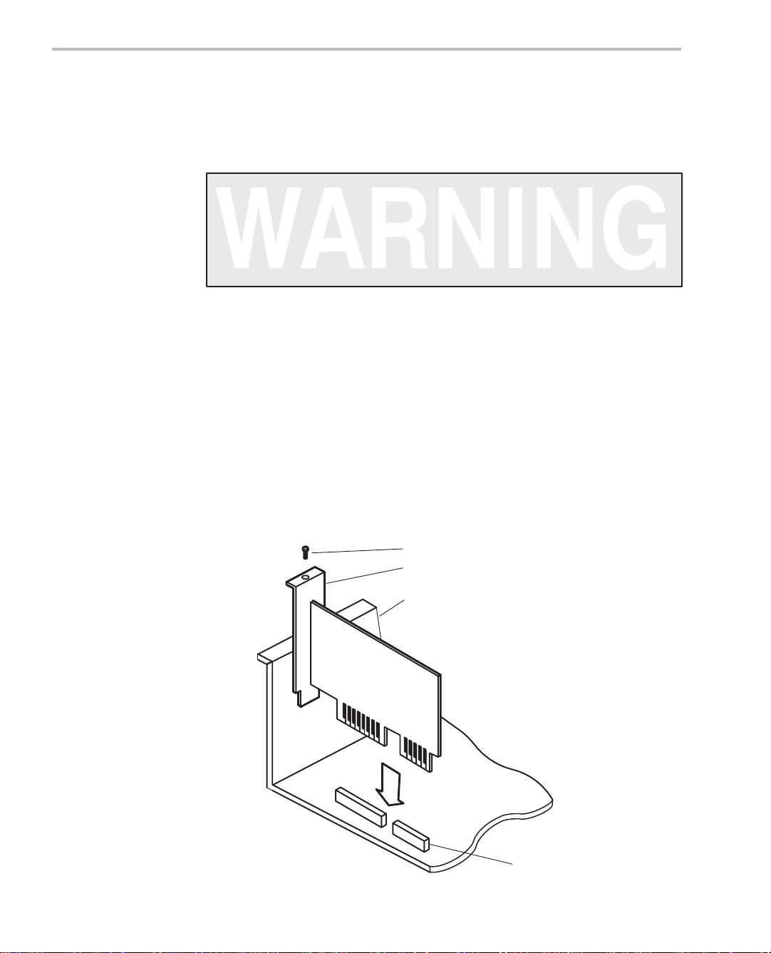
2.3 Step 2: Placing the XDS510 Into Your PC
After you’ve prepared the XDS510 for installation, follow these steps to place
it into your PC.
Minimizing Personal Injury
To minimize the risk of personal injury, always turn off the power
to your PC and unplug the power cord before installing the XDS510.
1) Turn off your PC’s power and unplug the power cord.
2) Remove the cover of your PC.
3) Remove the mounting bracket from an unused 16-bit slot.
4) Carefully but firmly push the XDS510 into a 16-bit slot (see Figure 2–2).
5) Return the mounting screw to the mounting bracket and tighten the screw
(see Figure 2–2). Note which slot contains the XDS510 for later use.
6) Replace the PC cover.
Figure 2–2. Placing the XDS510 Into Your PC
mounting screw
mounting bracket
rear of computer
XDS510
16-bit slot
2-4
Page 20
Step 3: Connecting the XDS510 to Your Target System
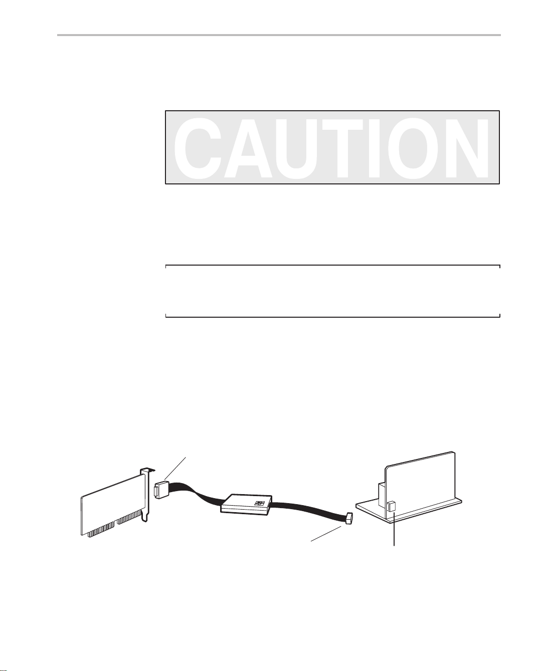
2.4 Step 3: Connecting the XDS510 to Your Target System
Follow these steps to connect your XDS510 to your target system.
Minimizing Equipment Damage
To minimize the risk of damage, be careful with the JTAG cable
connectors. Connect them gently; forcing the connectors into
position can damage them.
1) Turn off your target system and unplug the power cord.
2) Plug the 25-pin connector side of the JTAG cable into the XDS510 (see
Figure 2–3).
Note: If You Are Using the XDS511
If you are using the XDS511 emulator with or instead of a target system of
your own design, stop here and turn to Chapter 6, Installing the XDS51 1.
3) Plug the 14-pin connector side of the JT AG cable into the JT AG connector
on your target system. For information about creating the connector on
your target system, see the JT AG/MPSD Emulation T echnical Reference.
4) Plug in the power cord for your PC and target system.
5) Turn on your PC and target system.
Figure 2–3. Connecting the XDS510 and Your Target System
25-pin keyed
connector
XDS510
installed in
PC
JTAG cable
14-pin keyed
connector
target system
JTAG connector
2-5Installing the XDS510 in a PC
Page 21

Where to Go From Here
2.5 Where to Go From Here
Your XDS510 is now installed. At this point, do one of the following:
- If you plan to install the XDS51 1, turn to Chapter 6, Installing the XDS51 1.
- If you are not planning to install the XDS51 1, install the C source debugger
for your device. The installation instructions are in the getting started guide
for your device’s C source debugger.
Only after installing and running the C source debugger for your device can
you determine if the XDS510 is installed properly.
2-6
Page 22

Chapter 3
Installing the XDS510PP on a PC
This chapter explains how to install the XDS510PP emulator controller on your
PC.
Topic Page
3.1 What You’ll Need 3-2. . . . . . . . . . . . . . . . . . . . . . . . . . . . . . . . . . . . . . . . . . . . . .
3.2 Step 1: Connecting the XDS510PP to Your PC 3-3. . . . . . . . . . . . . . . . . . .
3.3 Step 2: Connecting the XDS510PP to Your Target System 3-4. . . . . . . .
3.4 Step 3: Supplying Power to the XDS510PP 3-5. . . . . . . . . . . . . . . . . . . . . .
3.5 Where to Go From Here 3-7. . . . . . . . . . . . . . . . . . . . . . . . . . . . . . . . . . . . . . .
3-1
Page 23

What You’ll Need
3.1 What You’ll Need
This section describes the required and optional hardware you need to install
the XDS510PP.
3.1.1 Required Hardware
To install the XDS510PP, you will need the following hardware:
host An IBM PC/AT or 100% compatible
parallel port One parallel printer port (LPT1 or LPT2)
emulator controller XDS510PP emulator controller
target system A system of your own design or an XDS51 1
emulator
JTAG connector A 14-pin connector (two rows of seven
pins) on your target system
printer cable 25-pin D-connector printer cable
3.1.2 Optional Hardware
T o install the XDS510PP, you might need the following hardware (see Section
3.4 on page 3-5):
Minimizing Electrical Shock and Fire Hazard
T o minimize the risk of electric shock and fire hazard, be sure that
all major components that you interface with Texas Instruments
devices are limited in energy and certified by one or more of the
following agencies: UL, CSA, VDE, or TUV.
emulator-controller
power supply
power supply
adapter cable
5 volts @ 1 ampere
6-inch power supply adapter cable
3-2
Page 24
Step 1: Connecting the XDS510PP to Your PC
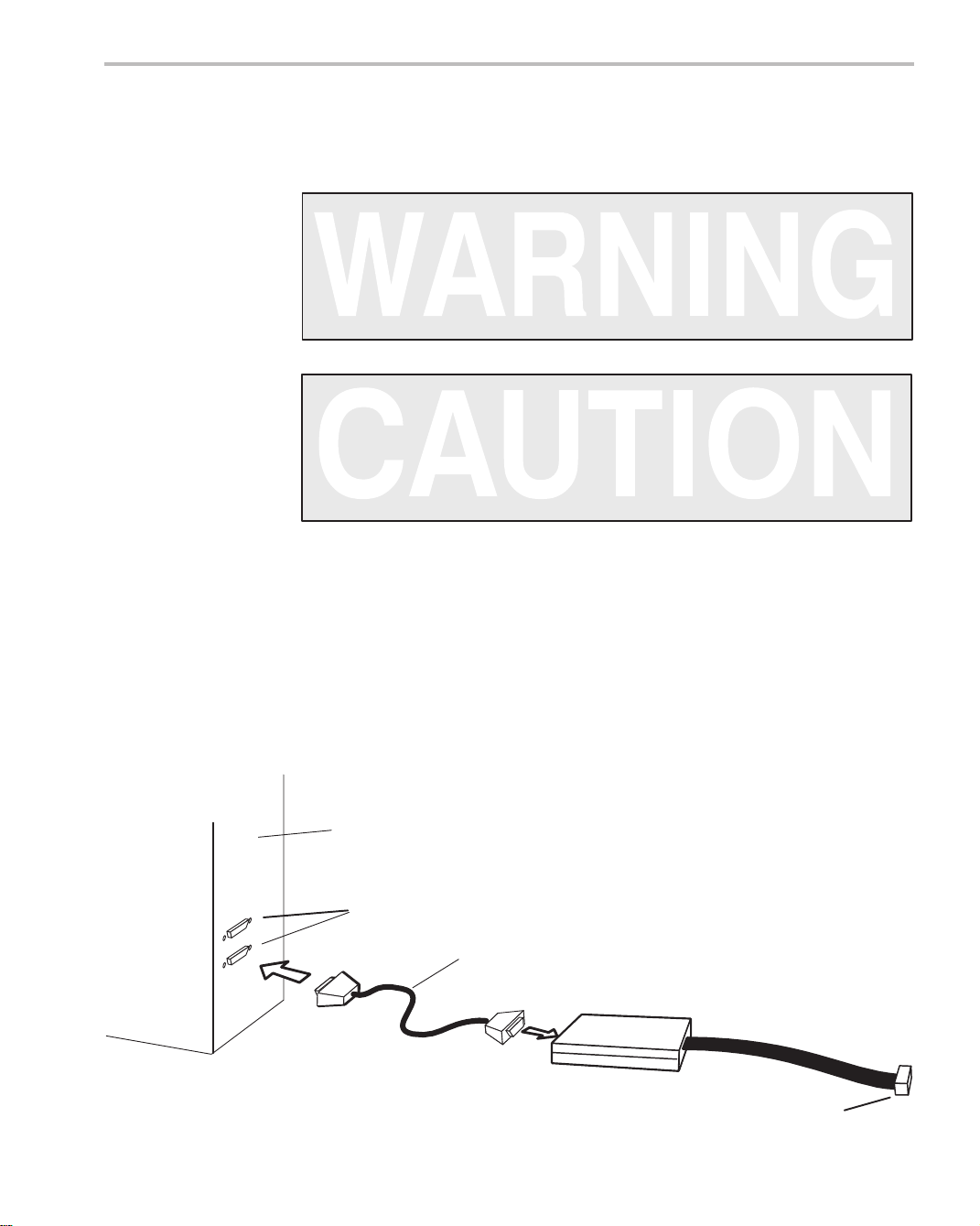
3.2 Step 1: Connecting the XDS510PP to Your PC
Follow these steps to connect the XDS510PP to your PC.
Minimizing Personal Injury
To minimize the risk of personal injury, always turn off the power
to your PC and unplug the power cord before installing the
XDS510PP.
Minimizing Equipment Damage
To minimize the risk of damage, be careful with the printer cable
connectors. Connect them gently; forcing the connectors into
position can damage them.
1) Turn off your PC’s power and unplug the power cord.
2) The printer port connections on the back of your PC are 25-pin female D
connectors. Connect one end of the printer cable to the printer port that
you intend to use—LPT1 or LPT2 (see Figure 3–1).
3) Connect the other end of the printer cable to the 25-pin connector on the
XDS510PP (see Figure 3–1).
Figure 3–1. Connecting the XDS510PP to Your PC
rear of PC
printer ports LPT1 and LPT2
printer cable
XDS510PP
14-pin keyed connector
3-3Installing the XDS510PP on a PC
Page 25
Step 2: Connecting the XDS510PP to Your Target System
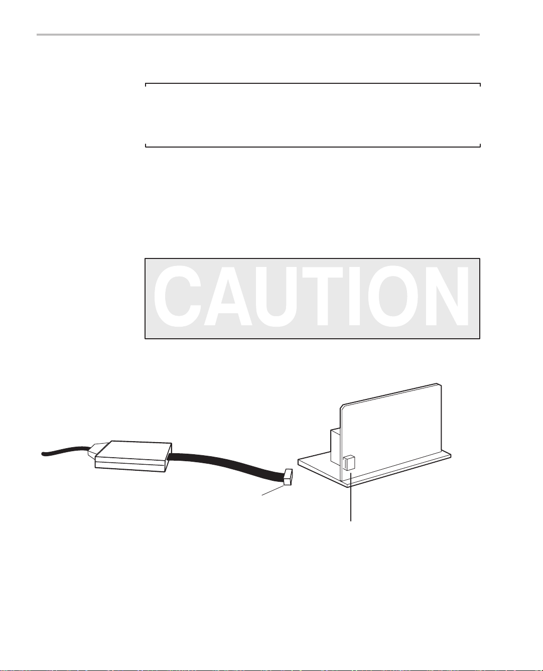
3.3 Step 2: Connecting the XDS510PP to Your Target System
Note: If You Are Using the XDS511
If you are using the XDS511 emulator with or instead of a target system of
your own design, stop here (that is, do not perform Step 2 or Step 3) and turn
to Chapter 6, Installing the XDS51 1.
1) Turn off your target system and unplug the power cord.
2) To connect the XDS510PP to your target system, plug the 14-pin connector on the XDS510PP cable into your target system (see Figure 3–2).
For information about creating the connector on your target system, see the
JTAG/MPSD Emulation Technical Reference.
Minimizing Equipment Damage
T o minimize the risk of damage, be careful with the XDS510PP cable
connectors. Connect them gently; forcing the connectors into
position can damage them.
Figure 3–2. Connecting the XDS510PP to Your Target System
XDS510PP
14-pin keyed connector
JTAG connector
3-4
target system
Page 26

3.4 Step 3: Supplying Power to the XDS510PP
The XDS510PP requires a power supply of 5 volts. How you supply power depends upon what the XDS510PP connects to. The following table describes
the possibilities:
Connection Scenario Power Supply Option
The XDS510PP is connected to
an XDS511.
Power is supplied by the XDS511. This is true
whether or not the XDS51 1 is connected to a target system. Y ou do not have to connect power directly to the XDS510PP. Connecting power directly to the XDS510PP when using the XDS51 1,
however, will not harm the XDS510PP or the
XDS511.
Step 3: Supplying Power to the XDS510PP
The XDS510PP is connected
directly to a 3-volt target system.
The XDS510PP is connected
directly to a 5-volt target system.
You must connect the provided power supply (5
volts @ 1 ampere) to the XDS510PP.
While you do not have to connect the provided
power supply to the XDS510PP, it is highly recommended. Connecting the power supply ensures that the XDS510PP receives enough power.
3-5Installing the XDS510PP on a PC
Page 27
Step 3: Supplying Power to the XDS510PP
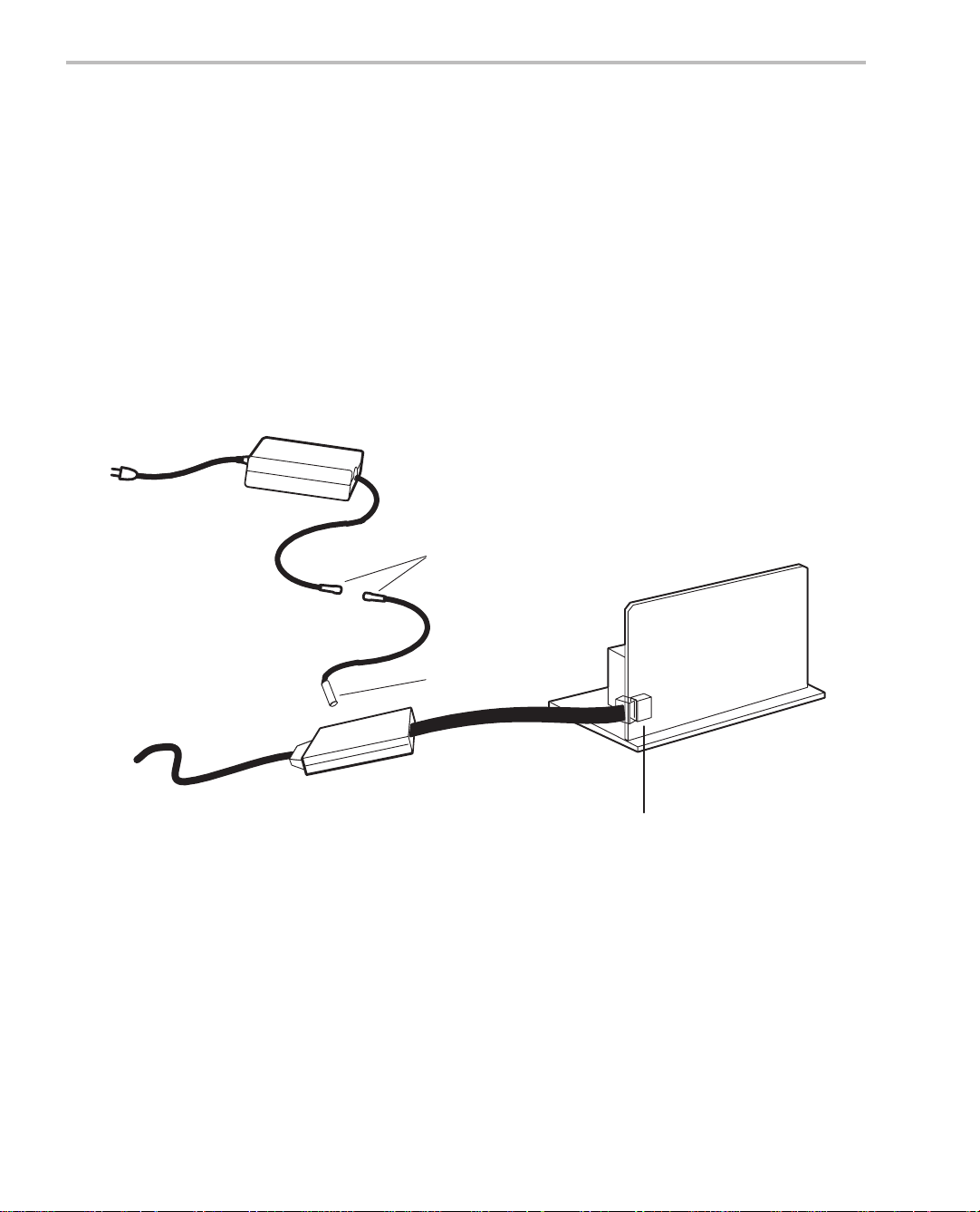
If you need to connect the power supply to the XDS510PP, follow these steps:
1) Connect the 2.1 mm barrel jack end of the power supply adapter cable to
the power jack on the XDS510PP (see Figure 3–3).
2) Connect the 5-pin circular connector end of the power supply adapter
cable to the power supply (at the circular connector of the DC power cord).
3) Plug in the power cord for your PC, XDS510PP , and target system. Turn
on your PC and target system.
Figure 3–3. Connecting the Power Supply Adapter Cable
power supply
5-pin circular
connectors
XDS510PP
power supply
adapter cable
2.1-mm barrel jack
target system
JTAG connector
3-6
Page 28

3.5 Where to Go From Here
Your XDS510PP is now installed. At this point, do one of the following:
- If you plan to install the XDS51 1, turn to Chapter 6, Installing the XDS51 1.
- If you are not planning to install the XDS51 1, install the C source debugger
for your device. The installation instructions are in the getting started guide
for your device’s C source debugger.
Only after installing and running the C source debugger for your device can
you determine if the XDS510PP is installed properly.
Where to Go From Here
3-7Installing the XDS510PP on a PC
Page 29

Chapter 4
Installing the XDS510WS on a SPARCstation
This chapter explains how to install the XDS510WS emulator controller on a
SPARCstation running OpenWindowst under SunOSt version 5.5 (or
higher).
Topic Page
4.1 What You’ll Need 4-2. . . . . . . . . . . . . . . . . . . . . . . . . . . . . . . . . . . . . . . . . . . . . .
4.2 Step 1: Preparing for the Installation 4-3. . . . . . . . . . . . . . . . . . . . . . . . . . . .
4.3 Step 2: Connecting the XDS510WS to Your Workstation 4-5. . . . . . . . . .
4.4 Step 3: Configuring Your Workstation to Recognize 4-10. . . . . . . . . . . .
the XDS510WS
4.5 Step 4: Allowing the Debugger to Access the XDS510WS 4-12. . . . . . .
4.6 Step 5: Connecting the XDS510WS to Your Target System 4-14. . . . . . .
4.7 Where to Go From Here 4-16. . . . . . . . . . . . . . . . . . . . . . . . . . . . . . . . . . . . . .
4.8 Uninstalling the XDS510WS 4-17. . . . . . . . . . . . . . . . . . . . . . . . . . . . . . . . . . .
4.9 Troubleshooting the XDS510WS 4-18. . . . . . . . . . . . . . . . . . . . . . . . . . . . . . .
4-1Installing the XDS510WS on a SPARCstation
Page 30

What You’ll Need
4.1 What You’ll Need
To install the XDS510WS, you will need the following hardware:
host A SPARCstation or 100% compatible sys-
tem
interface to host A SCSI bus controller with at least one free
SCSI identifier between 0 and 6
emulator controller An XDS510WS emulator controller
emulator-controller
power supply
SCSI cable A SCSI cable used for connecting the
SCSI terminator A SCSI bus terminator if the XDS510WS is
JTAG cable Cable that connects the XDS510 to your
target system A system of your own design or an XDS51 1
JTAG connector A 14-pin connector (two rows of seven
Minimizing Electrical Shock and Fire Hazard
The provided external power supply for the
XDS510WS (approximately 5 volts @ 3
ampere)
XDS510WS to your SPARCstation. The
SCSI cable packaged with your system is
a SCSI–2 to SCSI–2 cable. If your worksta-
tion has a SCSI–3 interface only, please
obtain a SCSI–3 to SCSI–2 cable, or use
a converter.
at the end of the SCSI chain
target system. The JTAG cable voltage
should match your target system.
emulator
pins) on your target system
1) To minimize the risk of electric shock and fire hazard, be sure that
all major components that you interface with Texas Instruments
devices are limited in energy and certified by one or more of the following agencies: UL, CSA, VDE, or TUV.
2) Turn the power off before you connect components and cables.
3) Never disconnect or reconnect any cables or other hardware devices while the XDS510WS is turned on.
4-2
Page 31

4.2 Step 1: Preparing for the Installation
To prepare for the installation, you must have the correct access to the host
machine, and you must determine if the XDS510WS is working correctly . This
section explains these requirements.
4.2.1 Access Required
You must have root access to the host machine you intend to connect to the
XDS510WS. If you do not, contact your system administrator.
4.2.2 Ensuring That the XDS510WS Is Working Correctly
Before you attach the XDS510WS to your workstation, be sure it is working
correctly . To do this, follow these steps. See Figure 4–1 and Figure 4–2 for illustrations of the XDS510WS.
1) Connect the power supply to the XDS510WS and plug in the power supply.
2) Turn on the XDS510WS.
Step 1: Preparing for the Installation
- LED 1 lights to indicate that the power is on. If LED 1 does not come
on, turn off the XDS510WS, check your power connections, and restart the XDS510WS.
- LED 6 lights to indicate that the XDS510WS is running through a self
test. Within a minute, the self–test should be done and LED 6 goes
out.
The XDS510WS is ready and running correctly when LEDs 1, 2, and 5 are on,
and all other LEDs are off. If these LEDs do not come on, something is wrong
with the XDS510WS. Recheck your connections and turn the XDS510WS off
and on a second time. If LED 1, 2, or 5 is still off, shut off the XDS510WS and
contact the TI DSP or Microcontroller Hotline (see the Preface). For detailed
information about the LEDs, see Appendix A, Interpreting the XDS510WS
LEDs.
4-3Installing the XDS510WS on a SP ARCstation
Page 32

Step 1: Preparing for the Installation
Figure 4–1. Rear View of the XDS510WS
on/off switch
power supply connector
Figure 4–2. Front View of the XDS510WS
4
XDS510WS
LEDs
123456 7 8
4-4
Page 33

Step 2: Connecting the XDS510WS to Your Workstation
4.3 Step 2: Connecting the XDS510WS to Your Workstation
The XDS510WS is connected to your workstation using a SCSI bus. This section describes how to locate a SCSI bus to use and how to connect the
XDS510WS to the SCSI bus.
Minimizing Electrical Shock and Equipment Damage
1) Never disconnect or reconnect any cables or other hardware
devices while the XDS510WS is turned on.
2) Be sure that all devices on the SCSI bus, your workstation, and
the XDS510WS are turned off before you connect the
XDS510WS to your workstation.
4.3.1 Locating a SCSI Bus With an Unused Identifier
Each SCSI controller in your workstation has its own SCSI bus. A workstation
usually has only one SCSI controller (unless you have added additional controller cards). The SCSI bus, on a card with only SCSI–2 connectors, can support up to eight devices (including the workstation), each uniquely numbered
0 through 7. The SCSI bus, on a card with at least one SCSI–3 connector, can
support up to 16 devices (including the workstation), each uniquely numbered
0 through 15.
Priority for the IDs is 7 to 0, 15 to 8, highest to lowest. Y our workstation is SCSI
ID 7 by default; it is recommended that this ID not be changed. The
XDS510WS uses SCSI ID 4 by default. If, however , SCSI ID 4 is already in use,
you must change the ID of the XDS510WS to one that is not used.
To get a list of the SCSI IDs used on your workstation, follow these steps:
1) As the root user, type the following command to get the PROM prompt:
halt
2) If you receive the following message:
Program terminated
Type b(boot), c(continue), or n(new command mode)
>
Type:
n
If you do not receive this message, skip to the next step.
4-5Installing the XDS510WS on a SP ARCstation
Page 34

Step 2: Connecting the XDS510WS to Your Workstation
3) For SunOS 5.5 skip to step 5. For SunOS 5.6, 5.7, and 5.8 type:
setenv auto–boot? false
4) After you receive the following message:
auto–boot? = false
Reset the workstation by typing the following for SunOS 5.6 or 5.7:
reset
Reset the workstation by typing the following for SunOS 5.8:
reset–all
If reset doesn’t work for 5.6 or 5.7, try reset–all. Similarly, if reset–all
doesn’t work for 5.8, try reset.
5) To probe the SCSI devices attached to the workstation enter the following
for SunOS 5.6 or 5.7:
probe–scsi
For SunOS 5.8, enter:
probe–scsi–all
The probe–scsi–all command can be used for all SunOS operating sys-
tems, but it is primarily used for probing workstations with multiple SCSI
cards. If probe–scsi does not work, try probe–scsi–all.
Y ou should see a list of used SCSI IDs scroll on your screen similar to the
following:
Target 3
Unit 0 disk SEAGATE ST1480 SUN Copyright (c) 1992
Seagate all rights reserved 0000
ok
The number following the word Target represents the currently used SCSI
IDs. In the above message, SCSI ID number 3 is taken. The workstation’s
SCSI ID is not in this list. Rather, it is stored in the PROM environment variable scsi_initiator_id and can be viewed at this point when you type prin-
tenv.
6) To revert the auto–boot? variable to the default value, type:
setenv auto–boot? true
The following message will appear:
auto–boot? = true
To continue with the regular SunOS boot for your workstation, type:
boot
4-6
Page 35

Step 2: Connecting the XDS510WS to Your Workstation
4.3.2 Setting the SCSI ID on the XDS510WS
If your workstation is already using SCSI ID 4 (see subsection 4.3.1), you must
change the SCSI ID on the XDS510WS. Follow these steps to change the
SCSI ID:
1) Turn off the XDS510WS.
2) Set the switch to a number of an unused SCSI ID.
The SCSI ID of the XDS510WS is controlled by a switch on its front panel
(see Figure 4–3). The switch has positions 0 to 9. Do not use settings 8
and 9. (The XDS510WS uses only the three LSBs of the switch number;
therefore, a setting of 8 would set the SCSI ID to 0, and a setting of 9 would
set the SCSI ID to 1.)
Figure 4–3. SCSI ID Switch on the XDS510WS
XDS510WS
4
push to
decrement
4
push to
increment
4-7Installing the XDS510WS on a SP ARCstation
Page 36

Step 2: Connecting the XDS510WS to Your Workstation
4.3.3 Adding the XDS510WS Onto the SCSI Bus
The SCSI bus is a chain with two distinct ends; it is not a loop. Although there
may be SCSI devices within your host, the visible chain begins at the host and
ends at one of the external SCSI devices.
Y ou can connect the XDS510WS into the SCSI bus anywhere along this chain.
Place the XDS510WS where you can easily connect it to your target system,
read the LEDs, and reach the power switch.
Minimizing Personal Injury
To minimize the risk of personal injury, always turn off the power
to your workstation and unplug the power cord before installing
the XDS510WS.
To connect the XDS510WS to your workstation, follow these steps:
1) Power down your workstation and SCSI devices, then unplug the power
cords.
2) For configurations using an external, 50-pin SCSI–2 interface:
a) Connect one end of a SCSI–2 to SCSI–2 cable to the back of the
XDS510WS. You can use either of the SCSI connectors that are on
the XDS510WS. See Figure 4–4.
b) Connect the other end of the SCSI–2 cable to the back of your
workstation or to another SCSI device.
3) For configurations using an external, 68-pin SCSI–3 interface:
a) Connect the 50-pin SCSI–2 connector of the SCSI–3 to SCSI–2 cable
to the back of the XDS510WS. Y ou can use either of the SCSI connectors that are on the XDS510WS. See Figure 4–4.
b) Connect the 68-pin connector of the SCSI–3 to SCSI–2 cable to the
back of your workstation or another compatible SCSI–3 device.
Note: Reduction in Maximum Transfer Rate
Due to restrictions in the SCSI interface, connection of a SCSI–2 device to
a SCSI–3 device chain reduces the maximum transfer rate along the bus.
The maximum SCSI–2 connection speed is 20MB/s, as compared to the potential 80MB/s or 160MB/s over SCSI–3. In most cases the external bus is
separated from the internal bus(es) of the SCSI card, and thus the
XDS510WS only affects transfer rates over external devices.
4-8
Page 37

Step 2: Connecting the XDS510WS to Your Workstation
Figure 4–4. Connecting the XDS510WS to Your Workstation
workstation
SCSI cable
SCSI connector or
external terminator
for the SCSI bus
SCSI connectors
4.3.4 Terminating the SCSI Bus
XDS510WS
You must terminate the SCSI bus at each end of its chain to reduce signal
noise. The device farthest from your workstation on the chain should be terminated. Terminating intervening devices can cause intermittent errors in the
SCSI bus.
If the XDS510WS is at the end of the SCSI bus, terminate the bus by connecting an external terminator (see Figure 4-4) to the unused SCSI connector on
the back of the XDS510WS.
Turn on all external SCSI devices (including the XDS510WS) from the farthest/
terminated device inward, then turn on your workstation.
Note: Terminator for SCSI–2 Only
The terminator packaged with the system is for use with a SCSI–2 device.
It will not work on a SCSI–3 device.
4-9Installing the XDS510WS on a SP ARCstation
Page 38

Step 3: Configuring Your Workstation to Recognize the XDS510WS
4.4 Step 3: Configuring Your Workstation to Recognize the XDS510WS
This step varies, depending on which version of the operating system you are
using. The following table directs you to the proper section:
Operating System See Subsection
SunOS 5.5 4.4.1
SunOS 5.6 4.4.2
SunOS 5.7 4.4.2
SunOS 5.8 4.4.2
4.4.1 Using SunOS 5.5
If you are using SunOS 5.5, follow these steps to have your workstation recognize the XDS510WS:
1) As the root user, enter:
halt
2) With the XDS510WS properly connected and powered up, reboot your
workstation with the following PROM command:
boot –r
3) Once the system comes back up, as the root user, execute the following
command:
/usr/sbin/disks
4) Go on to section 4.5 on page 4-12.
4-10
Page 39

4.4.2 Using SunOS 5.6, 5.7 or 5.8
If you are using SunOS 5.6, 5.7 or 5.8, follow these steps to have your workstation recognize the XDS510WS:
1) Make sure that the XDS510WS is properly connected and powered up.
2) Login as root, or login as a regular user and use the su command to
change to root.
3) Determine if the XDS510 driver has been previously installed on the
workstation with the following command:
ls /dev |grep xds
If the driver is installed, rxds510# will be returned where # is the SCSI ID of
the XDS510WS box. If the driver is installed, uninstall it using the instructions in section 4.8 on page 4-17 before installing the new driver.
4) Insert the CD and go to the soldrv directory on the CD.
5) Run the script by entering the following. Then follow the script directions.
solaris–drv–install.sh
Step 3: Configuring Your Workstation to Recognize the XDS510WS
6) When prompted, enter the lun number of the SCSI card. This applies to
workstations where there is more than one card present, if your workstation has only one card you should enter 0.
7) When prompted, enter the SCSI port number for the XDS510WS chosen
in section 4.3 on page 4-5 (default setting for the XDS510WS is 4).
8) Answer Yes when prompted to reboot the machine.
9) Go to section 4.5 on page 4-12.
4-11Installing the XDS510WS on a SPARCstation
Page 40

Step 4: Allowing the Debugger to Access the XDS510WS
4.5 Step 4: Allowing the Debugger to Access the XDS510WS
The debugger accesses the XDS510WS by reading from and writing to the device driver you defined in the EMULATOR configuration file. As a result, to
execute the debugger, you must have read/write privileges on the driver file.
This step varies, depending on which version of the operating system you are
using. The following table directs you to the proper section:
Operating System See Subsection
SunOS 5.5 4.5.1
SunOS 5.6 4.5.2
SunOS 5.7 4.5.2
SunOS 5.8 4.5.2
4.5.1 Using SunOS 5.5
If you are using SunOS 5.5, nothing further is required. To confirm proper operation, enter:
ls –l /dev/rsd*a
If rsd#a is not listed (where # is a device driver number), repeat the steps in
section 4.4.1 on page 4-10.
If rsd#a is listed with permissions other than lrwxrwxrwx, enter the following
command:
chmod 777 /dev/rsd#d
4.5.2 Using SunOS 5.6, 5.7 or 5.8
To confirm proper operation if you are using SunOS 5.6, 5.7, or 5.8, enter:
ls –l /dev/rxds510#
If rxds510# is not listed (where # is the SCSI ID of the device), repeat the steps
in section 4.4.2 on page 4-11.
At the end of the line you should also see something similar to:
/xds510@4,0:character
Where, in this example, the 4 following the @ is the SCSI ID chosen in section
4.3 on page 4-5, and 0 represents the lun number of the SCSI card. The lun
number should be 0 unless the XDS510WS is connected to a secondary SCSI
card on the workstation.
4-12
Page 41

Step 4: Allowing the Debugger to Access the XDS510WS
If rxds510# is listed with permissions other than lrwxrwxrwx, enter the following command:
chmod 777 /dev/rxds510#
To ensure that correct permissions are set on the actual device, enter the following command:
ls –lL /dev/rxds510#
If rxds510# is listed with permissions other than crwxrwxrwx, enter the following command:
chmod 777 /dev/rxds510#
Note: False Warning Message
When booting your workstation you may notice an error displayed as follows:
WARNING: {device location}/sd@4,0 (sd4):
corrupt label – wrong magic number
{device location} refers to the directory as displayed after executing the following command, starting from after ../devices/:
ls –l /dev/rxds510#
This error has not proven to be of any significant problem with operation of the
XDS510WS, and can be ignored.
4-13Installing the XDS510WS on a SP ARCstation
Page 42

Step 5: Connecting the XDS510WS to Your Target System
4.6 Step 5: Connecting the XDS510WS to Your Target System
Follow these steps to connect the JTAG cable to your XDS510WS and your
target system. Figure 4–5 illustrates the connection.
Minimizing Equipment Damage
To minimize the risk of damage, be careful with the JTAG cable
connectors. Connect them gently; forcing the connectors into
position can damage them.
Remember , the connectors are keyed. Be sure to connect the cable
so that the keys fit in the correct slots.
1) Power down your SCSI devices, workstation, XDS510WS, and target system. Unplug all of the power cords.
2) Plug the 25-pin connector side of the JTAG cable into the XDS510WS. The
connector is keyed to ensure proper connection.
Note: If You Are Using the XDS511
If you are using the XDS511 emulator with or instead of a target system of
your own design, stop here (that is, complete only steps 1 and 2 of this section) and turn to Chapter 6, Installing the XDS51 1.
3) Plug the 14-pin connector side of the JTAG cable into the JT AG connector
on your target system. The connector is keyed to ensure a proper connection. For information about creating the connector on your target system,
see the JT AG/MPSD Emulation Technical Reference.
4) Plug in the power cords for your workstation, SCSI devices, XDS510WS,
and target system.
5) Turn on your SCSI devices, workstation, XDS510WS, and target system.
Figure 4–5. Connecting Your Target System
25-pin keyed
XDS510WS
4-14
connector
JTAG cable
14-pin keyed
connector
target system
JTAG connector
Page 43

Step 5: Connecting the XDS510WS to Your Target System
If you want to change the target system connected to the JT AG cable, then follow these steps:
1) Power off the XDS510WS and the target systems.
2) Disconnect the 14-pin connector side of the JTAG cable from the old target
system, and connect it to the new target system.
3) Power on the XDS510WS.
4) Power on the new target system.
The workstation can be left running, provided that the SCSI cable(s) connecting the workstation to the XDS510WS and any other SCSI devices are left connected, and that the XDS510WS is only powered off for a short period of time.
4-15Installing the XDS510WS on a SP ARCstation
Page 44

Where to Go From Here
4.7 Where to Go From Here
Your XDS510WS is now installed. At this point, do one of the following:
- If you plan to install the XDS51 1, turn to Chapter 6, Installing the XDS51 1.
- If you are not planning to install the XDS51 1, install the C source debugger
for your device. The installation instructions are in the getting started guide
for your device’s C source debugger.
Only after installing and running the C source debugger for your device can
you determine if the XDS510WS is installed properly.
4-16
Page 45

4.8 Uninstalling the XDS510WS
To uninstall the XDS510WS from your system, follow these steps:
1) Login as root, or login as a regular user and use the su command to
change to root.
2) Enter this command:
/usr/sbin/rem_drv xds510
3) Remove the dangling symbolic link rxds510# in /dev. The # sign represents the SCSI ID of the XDS510WS device.
4) Remove the following line from the /etc/devlink.tab file:
type=sample_driver;name=xds510;minor=character rxds510\A1
5) If the following files are present, remove them:
/usr/kernel/drv/xds510
/usr/kernel/drv/xds510.conf
/usr/kernel/drv/sparcv9/xds510
Uninstalling the XDS510WS
6) Reboot the system.
4-17Installing the XDS510WS on a SP ARCstation
Page 46

T roubleshooting the XDS510WS
4.9 Troubleshooting the XDS510WS
Before looking for troubleshooting help in this section, please make sure that
the XDS510WS is in proper working order. Make sure that the device is properly powered and all cable connections are securely attached to the
XDS510WS, target, and workstation. If you have reason to believe that the
XDS510WS is broken or damaged, refer to section 4.2.2 on page 4-3, or contact the TI DSP or Microcontroller Hotline.
4.9.1 Unable to Load Device Driver
If you are unable to load the device driver, follow these steps:
1) Make sure that the correct driver file is being used:
a) Determine the correct device driver for your current target.
b) Load driver, if different than the previously loaded one.
2) Ensure that the correct SCSI ID is being referenced by the driver. Check
the currently used SCSI IDs by using the probe command in Unix (see section 4.3 on page 4-5 for details).
3) If steps 1 and 2 are not helpful, the XDS510WS may need to be reset. It
is not necessary to power down the workstation so long as the XDS510WS
is being powered off for a short period of time.
a) Using a board with a working reset switch:
i) Make sure that no programs are running for your debugger.
ii) Power off the XDS510WS.
iii) Power on the XDS510WS.
iv) Reset the target board.
v) Reload the target device driver.
b) Using a board without a reset switch:
i) Make sure that no programs are running for your debugger.
ii) Power off the target board then the XDS510WS.
iii) Power on XDS510WS then the target board.
iv) Reload the target device driver.
4-18
Page 47

4.9.2 Code Composer Errors on Initial Use
If the attempt to execute Code Composer Studio for the first time results in one
of the following error messages:
Can’t Initialize Target DSP. Trouble with JTAG controller,
check your Cabling and your Multiprocessing Configuration
Can’t Initialize Target DSP. I/O port – <address>
There are several troubleshooting areas to consider when encountering this
error. These are listed below from most likely to least likely to have invoked this
error message.
1) Make sure that the device driver loaded onto the XDS510WS matches the
actual target.
2) Check the Code Composer Studio Setup Configuration. To do that, launch
Code Composer Studio Setup, right-click on the board name in the left
pane, and select Properties from the context menu.
a) Select the Board Name tab of the Board Properties dialog, and check
that the board data match the actual target.
b) Select the Board Properties tab of the Board Properties dialog, and
make sure that the I/O port address set for the target board matches
the actual SCSI address of the XDS510WS.
T roubleshooting the XDS510WS
c) If you are using a multi-processor board or multiple boards, select the
Processor Configuration tab of the Board Properties dialog, and
check that the type and order of processors matches that on the actual
target.
Please refer to the Code Composer Studio Setup online help for details on
correctly configuring your Code Composer Studio Multiprocessing System.
3) Check the DSP Target Setup.
a) Make sure your DSP is not in a Hold or a Reset state and is correctly
powered up.
b) Check that the target processor pin is not active. The target processor
must be ready for the debugger to execute. If there is a hardware problem on the ready line, if possible, put the processor into Microcomputer mode, reset the system, and try bringing up the debugger again. In
Microcomputer mode, all memory accesses should be on-chip and
the ready signal should have no effect. Check your device user’s
guide for details.
c) Check that the processor hold pin is not active. Same issue as the tar-
get process pin being active.
4-19Installing the XDS510WS on a SP ARCstation
Page 48

T roubleshooting the XDS510WS
d) The JTAG signal may not be clear enough. In order to provide high-
quality signals between the emulator and the target processor, check
that the unbuffered distance between the emulator header and the
processor is less than 6 inches. If this distance is in excess of 6 inches,
the emulation signals should be buffered.
e) The processor may not have a clock out. Processor must be receiving
and generating the proper clocks. Check your clock in circuit and clock
mode.
f) Check that the EMU0/1 pins are high. The value of the EMU0/1 pins
and reset can be used to turn off device pins and/or invoke device test
modes. You should have these pins pulled high through a resistor in
your target system.
4.9.3 Intermittent Errors Occur With Code Composer Studio for Solaris
Three types of intermittent errors might be occasionally observed when debugging a program in Code Composer Studio for Solaris using the
XDS510WS:
- Code Composer Studio is launched after all hardware is properly con-
nected and all settings correctly set, but it produces an error message like:
Can’t initialize target CPU: Target initialization failed
-
Code Composer Studio is launched without errors or warnings, but an attempt to load a program onto the target results in an error message like:
Data verification failed at address address
- Code Composer Studio is successfully launched and a program is suc-
cessfully loaded onto the target, but an attempt to run or step through the
program results in an error message such as the following:
Data verification failed at address address
or
Can’t run target CPU
To recover after any of the above listed errors, follow these steps:
1) Exit Code Composer Studio for Solaris.
2) Reset the system as described in step 3 of section 4.9.1 on page 4-18.
3) Start Code Composer Studio for Solaris.
In case occurrence of the above listed errors significantly hinders debugging,
consider using a shorter SCSI cable to connect your workstation to the
XDS510WS.
4-20
Page 49

Chapter 5
Installing the XDS510WS on an HP W orkstation
This chapter explains how to install the XDS510WS emulator controller on an
HP 9000 Series 700t PA-RISCt computer running HP-UXt 9.0x.
Topic Page
5.1 What You’ll Need 5-2. . . . . . . . . . . . . . . . . . . . . . . . . . . . . . . . . . . . . . . . . . . . . .
5.2 Step 1: Preparing for the Installation 5-3. . . . . . . . . . . . . . . . . . . . . . . . . . . .
5.3 Step 2: Connecting the XDS510WS to Your Workstation 5-5. . . . . . . . . .
5.4 Step 3: Setting Up Your Workstation to Recognize 5-9. . . . . . . . . . . . . . .
the XDS510WS
5.5 Step 4: Allowing the Debugger to Access the XDS510WS 5-10. . . . . . .
5.6 Step 5: Connecting the XDS510WS to Your Target System 5-11. . . . . . .
5.7 Where to Go From Here 5-12. . . . . . . . . . . . . . . . . . . . . . . . . . . . . . . . . . . . . .
5-1Installing the XDS510WS on an HP Workstation
Page 50

What You’ll Need
5.1 What You’ll Need
To install the XDS510WS, you will need the following hardware:
host An HP 9000 Series 700 PA-RISC comput-
er
interface to host A SCSI bus controller with at least one free
SCSI identifier
emulator controller An XDS510WS emulator controller
emulator-controller
power supply
SCSI cable A SCSI cable used for connecting the
SCSI terminator A SCSI bus terminator if the XDS510WS is
JTAG cable Cable that connects the XDS510 to your
target system A system of your own design or an XDS51 1
JTAG connector A 14-pin connector (two rows of seven
Minimizing Electrical Shock and Fire Hazard
1) To minimize the risk of electric shock and fire hazard, be sure that
all major components that you interface with Texas Instruments
devices are limited in energy and certified by one or more of the following agencies: UL, CSA, VDE, or TUV.
2) Turn the power off before you connect components and cables.
The provided external power supply for the
XDS510WS (approximately 5 volts @ 3
ampere)
XDS510WS to your HP workstation
at the end of the SCSI chain
target system
emulator
pins) on your target system
3) Never disconnect or reconnect any cables or other hardware devices while the XDS510WS is turned on.
5-2
Page 51

5.2 Step 1: Preparing for the Installation
To prepare for the installation, you must have the correct access to the host
machine, and you must determine if the XDS510WS is working correctly . This
section explains these requirements.
5.2.1 Access Required
You must have root access to the host machine you intend to connect to the
XDS510WS. If you do not, contact your system administrator.
5.2.2 Ensuring That the XDS510WS Is Working Correctly
Before you attach the XDS510WS to your workstation, be sure it is working
correctly . To do this, follow these steps. See Figure 5–1 and Figure 5–2 for illustrations of the XDS510WS.
1) Connect the power supply to the XDS510WS and plug in the power supply.
2) Turn on the XDS510WS.
Step 1: Preparing for the Installation
- LED 1 lights to indicate that the power is on. If LED 1 does not come
on, turn off the XDS510WS, check your power connections, and restart the XDS510WS.
- LED 6 lights to indicate that the XDS510WS is running through a self
test. Within a minute, the self–test should be done and LED 6 goes
out.
The XDS510WS is ready and running correctly when LEDs 1, 2, and 5 are on,
and all other LEDs are off. If these LEDs do not come on, something is wrong
with the XDS510WS. Recheck your connections and turn the XDS510WS off
and on a second time. If LED 1, 2, or 5 is still off, shut off the XDS510WS and
contact the TI DSP or Microcontroller Hotline (see the Preface). For detailed
information about the LEDs, see Appendix A, Interpreting the XDS510WS
LEDs.
5-3Installing the XDS510WS on an HP Workstation
Page 52

Step 1: Preparing for the Installation
Figure 5–1. Rear View of the XDS510WS
on/off switch
power supply connector
Figure 5–2. Front View of the XDS510WS
4
XDS510WS
LEDs
123456 7 8
5-4
Page 53

Step 2: Connecting the XDS510WS to Your Workstation
5.3 Step 2: Connecting the XDS510WS to Your Workstation
The XDS510WS is connected to your workstation using a SCSI bus. This section describes how to locate a SCSI bus to use and how to connect the
XDS510WS to the SCSI bus.
Minimizing Electrical Shock and Equipment Damage
1) Never disconnect or reconnect any cables or other hardware
devices while the XDS510WS is turned on.
2) Be sure that all devices on the SCSI bus, your workstation, and
the XDS510WS are turned off before you connect the
XDS510WS to your workstation.
5.3.1 Locating a SCSI Bus With an Unused Identifier
Each SCSI controller in your workstation has its own SCSI bus, and a
workstation usually has only one SCSI controller (unless you have added
additional controller cards). A single bus can support up to eight different
devices (including the workstation), each uniquely numbered 0 through 7, with
the higher priority devices assigned to the larger SCSI ID numbers. Y our workstation is SCSI ID 7 by default. CD-ROM drives are ID 6 by default. The
XDS510WS uses SCSI ID 4 by default. If, however , SCSI ID 4 is already in use,
you must change the ID of the XDS510WS to one that is not used.
To get a list of the used SCSI IDs on your workstation, follow these steps.
1) As the root user, enter the following command:
/usr/bin/sam
2) Once SAM (System Administration Manager) is running, select View All
from the Peripheral Devices menu.
5-5Installing the XDS510WS on an HP Workstation
Page 54

Step 2: Connecting the XDS510WS to Your Workstation
Y ou should see a list of used SCSI IDs scroll on your screen; it should look similar to the following:
Path Driver Description Status
==== ====== =========== ======
1.0.0 graph3 Graphics Subsystem ok
2.0.1 c700 SCSI Interface ok
2.0.1.4.0 scsi SCSI CD-ROM drive ok
2.0.1.5.0 scsi SCSI Disk Drive ok
2.0.1.6.0 scsi SCSI Seagate ST31200N Disk Drive ok
2.0.2 lan01 LAN Interface ok
2.0.4 asio0 RS-232 Interface ok
2.0.6 parallel Parallel Interface ok
2.0.8 audio Audio Interface ok
2.0.11 ps2 Keyboard/Mouse Port ok
2.0.12 ps2 Keyboard/Mouse Port ok
The currently active SCSI devices have SCSI as their driver type and the name
x.x.x.Y.0, where Y is the SCSI ID on the x.x.x controller. In this example, the
XDS510WS is described as the SCSI Disk Drive, the controller (x.x.x) is 2.0.1,
and the SCSI ID (Y) is 5.
5.3.2 Setting the SCSI ID on the XDS510WS
If your workstation is already using SCSI ID 4 (see subsection 5.3.1), you must
change the SCSI ID on the XDS510WS. Follow these steps to change the
SCSI ID:
1) Turn off the XDS510WS.
2) Set the switch to a number of an unused SCSI ID.
The SCSI ID of the XDS510WS is controlled by a switch on its front panel
(see Figure 5–3). This switch has ten positions, 0 through 9. Do not use
settings 8 and 9. (The XDS510WS uses only the three LSBs of the switch
number; therefore, a setting of 8 would set the SCSI ID to 0, and a setting of
9 would set the SCSI ID to 1.)
Figure 5–3. Front View of the XDS510WS
XDS510WS
4
push to
decrement
4
push to
increment
5-6
Page 55

Step 2: Connecting the XDS510WS to Your Workstation
5.3.3 Adding the XDS510WS Onto the SCSI Bus
The SCSI bus is a chain with two distinct ends; it is not a loop. Although there
may be SCSI devices within your host, the visible chain begins at the host and
ends at one of the external SCSI devices.
Y ou can connect the XDS510WS into the SCSI bus anywhere along this chain.
It is best, however, to place the XDS510WS where you can easily connect it
to your target system. The LEDs on the XDS510WS should be visible and its
power switch readily accessible.
Minimizing Personal Injury
To minimize the risk of personal injury, always turn off the power
to your workstation and unplug the power cord before installing
the XDS510WS.
To connect the XDS510WS to your workstation, follow these steps:
1) Turn off the power to your workstation and SCSI devices, and unplug the
power cords.
2) Connect one end of a SCSI cable to the back of the XDS510WS. You can
use either of the SCSI connectors that are on the XDS510WS. See
Figure 5–4.
3) Connect the other end of the SCSI cable to the back of your workstation
or to another SCSI device.
Figure 5–4. Connecting the XDS510WS to Your Workstation
workstation
SCSI cable
SCSI connector or external
terminator for the SCSI bus
SCSI connectors
XDS510WS
5-7Installing the XDS510WS on an HP Workstation
Page 56

Step 2: Connecting the XDS510WS to Your Workstation
5.3.4 Terminating the SCSI Bus
You must terminate the SCSI bus at each end of its chain to reduce signal
noise. The device farthest from your workstation on the chain should be terminated. Terminating intervening devices can cause intermittent errors in the
SCSI bus.
If the XDS510WS is at the end of the SCSI bus, terminate the bus by connecting the external terminator (see Figure 5-4) to the unused SCSI connector on
the back of the XDS510WS.
Turn on all external SCSI devices (including the XDS510WS) then turn on your
workstation.
5-8
Page 57

Step 3: Setting Up Your Workstation to Recognize the XDS510WS
5.4 Step 3: Setting Up Your Workstation to Recognize the XDS510WS
Ensure that the device driver exists. Look for file /dev/rdsk/cXdYs0, where X
is the ID of the SCSI controller that the emulator is attached to and Y is the
SCSI ID of the emulator. Usually X is 201.
If this file does not exist, get your system administrator to help you create one
with the HP mkdev utility.
5-9Installing the XDS510WS on an HP Workstation
Page 58

Step 4: Allowing the Debugger to Access the XDS510WS
5.5 Step 4: Allowing the Debugger to Access the XDS510WS
The debugger accesses the XDS510WS by reading from and writing to the device driver you looked for in Section 5.4.
To execute the debugger, you must ensure that any user who uses the
XDS510WS has read/write privileges for the /dev/rdsk/cXdYs0 file. To determine the read/write privileges, enter the following command:
ls –l /dev/rdsk/cXdYs0
If the file does not have the appropriate read/write privileges, as the root user,
enter the following command:
chmod a+rw /dev/rdsk/cXdYs0
5-10
Page 59

Step 5: Connecting the XDS510WS to Your Target System
5.6 Step 5: Connecting the XDS510WS to Your Target System
Follow these steps to connect the JTAG cable to your XDS510WS and your
target system. Figure 5–5 on page 5-11 illustrates the connection.
Minimizing Equipment Damage
To minimize the risk of damage, be careful with the JTAG cable
connectors. Connect them gently; forcing the connectors into
position can damage them.
Remember , the connectors are keyed. Be sure to connect the cable
so that the keys fit in the correct slots.
1) Turn off the power to your SCSI devices, workstation, XDS510WS, and
target system. Unplug all of the power cords.
2) Plug the 25-pin connector side of the JTAG cable into the XDS510WS. The
connector is keyed to ensure proper connection.
Note: If Using the XDS511
If you are using the XDS511 emulator with or instead of a target system of
your own design, stop here (that is, complete only Step 1 of this section) and
turn to Chapter 6, Installing the XDS51 1.
3) Plug the 14-pin connector side of the JTAG cable into the JT AG connector
on your target system. The connector is keyed to ensure a proper connection. For information about creating the connector on your target system,
see the JT AG/MPSD Emulation Technical Reference.
4) Plug in the power cords for your workstation, SCSI devices, XDS510WS,
and target system.
5) Turn on your SCSI devices, workstation, XDS510WS, and target system.
Figure 5–5. Connecting Your Target System
25-pin keyed
XDS510WS
connector
JTAG cable
14-pin keyed
connector
target system
JTAG connector
5-11Installing the XDS510WS on an HP Workstation
Page 60

Where to Go From Here
5.7 Where to Go From Here
Your XDS510WS is now installed. At this point, do one of the following:
- If you plan to install the XDS51 1, turn to Chapter 6, Installing the XDS51 1.
- If you are not planning to install the XDS51 1, install the C source debugger
for your device. The installation instructions are in the getting started guide
for your device’s C source debugger.
Only after installing and running the C source debugger for your device can
you determine if the XDS510WS is installed properly.
5-12
Page 61

Chapter 6
Installing the XDS511
This chapter describes how to set up and install the XDS51 1 emulator board.
If you plan to use the XDS51 1 as your target system, follow the instructions in
this chapter.
Topic Page
6.1 What You’ll Need 6-2. . . . . . . . . . . . . . . . . . . . . . . . . . . . . . . . . . . . . . . . . . . . . .
6.2 The XDS511 6-3. . . . . . . . . . . . . . . . . . . . . . . . . . . . . . . . . . . . . . . . . . . . . . . . . .
6.3 Step 1: Setting the Jumpers on the XDS511 6-4. . . . . . . . . . . . . . . . . . . . .
6.4 Step 2: Connecting the SE Device to the XDS511 6-7. . . . . . . . . . . . . . . .
6.5 Step 3: Connecting the JTAG Cable, Power Supply, and 6-9. . . . . . . . . .
Adapter Board
6.6 Step 4: Connecting a Target System to the XDS511 (Optional) 6-11. . .
6.7 Where to Go From Here 6-14. . . . . . . . . . . . . . . . . . . . . . . . . . . . . . . . . . . . . .
6-1
Page 62

What You’ll Need
6.1 What You’ll Need
This section describes the required and optional hardware you need to install
the XDS51 1.
6.1.1 Required Hardware
To install the XDS511, you will need the following hardware:
emulator controller An XDS510, XDS510PP , or XDS510WS
installed as described in Chapters 2–5
emulator XDS511 emulator board
6.1.2 Optional Hardware
To install the XDS511, you might want the following hardware:
Minimizing Electrical Shock and Fire Hazard
T o minimize the risk of electric shock and fire hazard, be sure that
all major components that you interface with Texas Instruments
devices are limited in energy and certified by one or more of the
following agencies: UL, CSA, VDE, or TUV.
emulator power
supply
power supply
adapter cable
target cable adapter
board
SE device SE device for the C8, C16, or C2xx
target system A system of your own design
target cable A cable that you purchase from TI to con-
The provided external power supply for
the XDS510WS (approximately 5 volts @
3 ampere)
6-inch power supply adapter cable
Adapter board
nect the XDS511 to your target system
Minimizing Static Shock
Special handling methods and materials should be used to prevent
equipment damage. You should be familiar with identification and
handling of ESD sensitive devices before attempting to perform the
procedures described in this manual.
6-2
Page 63

6.2 The XDS511
Figure 6–1 and Figure 6–2 show the top and bottom views of the XDS511
emulator and call out components that are referred to in this chapter.
Figure 6–1. XDS511 Emulator Top View
pin 1
The XDS511
power jack
JTAG connector
JP5
XDS511 EMULATORU1
Figure 6–2. XDS511 Bottom View
JP7
JP8
JP6
device socket
JP2
JP1
JP3
6-3Installing the XDS51 1
Page 64

Step 1: Setting the Jumpers on the XDS51 1
6.3 Step 1: Setting the Jumpers on the XDS511
The XDS51 1 has two blocks of jumpers that must be set. The locations of the
jumper blocks are shown in Figure 6–1 on page 6-3.
To set a pair of jumpers, place a jumper on the pins that correspond to the
jumper numbers. To disable a setting, remove the jumper from the pins that
correspond to the jumper numbers.
The jumpers are set to correspond to the SE device that you are using.
SE Device Used See Subsection
C8
C16
C2xx
6.3.1 Jumper Settings When Using a C8 or C16 SE Device
The following table shows the jumper settings for jumper blocks 1 and 5 (JP1
and JP5) when using the C8 or C16 SE device.
6.3.1
6.3.1
6.3.2
Jumper block TMS370C8 TMS370C16
Jumper block 1 (JP1)
Jumper block 5 (JP5)
(14) (13)
2
2
(11)(12)
(9)(10)
(7)(8)
(5)(6)
(3)(4)
1
(13)(14)
(11)(12)
(9)(10)
(7)(8)
(5)(6)
(3)(4)
1
(14) (13)
2
2
(11)(12)
(9)(10)
(7)(8)
(5)(6)
(3)(4)
1
(13)(14)
(11)(12)
(9)(10)
(7)(8)
(5)(6)
(3)(4)
1
6-4
Page 65

Step 1: Setting the Jumpers on the XDS51 1
6.3.2 Jumper Settings When Using a C2xx SE Device
When using the C2xx SE device, the jumper settings for the XDS51 1 vary depending upon which operating mode you use. These modes are:
native The XDS511 replacement memory is disabled. Memory
access is on-chip or on the C2xx logic interface.
EPROM The C2xx on-chip ROM is replaced by the XDS511
EPROM. The XDS511 is limited to 50-ns operation when
35-ns EPROMs are used.
RAM The C2xx on-chip ROM is replaced by the XDS511 RAM
bank 1.
fast-RAM The C2xx on-chip ROM is replaced by the XDS511 RAM
bank 1. The memory timing signals are advanced to
achieve faster operating speed. The replacement RAMs
are continuously enabled, consuming more power than
RAM mode.
boot The contents of the EPROM are copied to RAM bank 2 on
reset. The EPROMs are enabled continuously during copying. Writes to RAM bank 2 occur at the end of a cycle, and
one complete read/write cycle takes two clock cycles. The
EPROM is disabled at the end of the copy operation, and
the normal device reset occurs.
Jumper settings for 1–2, 3–4, 5–6, and 7–8 for both JP1 and JP5 are the same
for all operating modes. These settings are shown in Figure 6–3. The remaining jumpers vary and are shown in Table 6–1.
Figure 6–3. Jumper Settings That Remain the Same for All Modes
JP1
(7)(8)
(5)(6)
(3)(4)
2
1
2
JP5
(7)(8)
(5)(6)
(3)(4)
1
6-5Installing the XDS51 1
Page 66

Step 1: Setting the Jumpers on the XDS51 1
Table 6–1. Jumper Settings That Change for the Various Modes
If you want
this mode . . .
And you want . . .
Native ––
EPROM ––
RAM The debugger to always write to replace-
ment memory, and the CPU to write to replacement memory when memory mapping
overlay functions are enabled
RAM T o boot on the power up of the XDS51 1. Y ou
must have programmed EPROMs inserted.
RAM To boot on the power up of the XDS511
and on the power up of the CPU. You must
have programmed EPROMs inserted.
Fast-RAM The debugger to always write to replace-
ment memory, and the CPU to write to replacement memory when memory mapping
overlay functions are enabled
Fast-RAM To boot on the power up of the XDS51 1. You
must have programmed EPROMs inserted.
Then set JP1
like this . . .
(14) (13)
(11)(12)
(9)(10)
(14) (13)
(11)(12)
(9)(10)
(14) (13)
(11)(12)
(9)(10)
(14) (13)
(11)(12)
(9)(10)
(14) (13)
(11)(12)
(9)(10)
(14) (13)
(11)(12)
(9)(10)
(14) (13)
(11)(12)
(9)(10)
And set JP5
like this . . .
(14) (13)
(11)(12)
(9)(10)
(14) (13)
(11)(12)
(9)(10)
(14) (13)
(11)(12)
(9)(10)
(14) (13)
(11)(12)
(9)(10)
(14) (13)
(11)(12)
(9)(10)
(14) (13)
(11)(12)
(9)(10)
(14) (13)
(11)(12)
(9)(10)
Fast-RAM To boot on the power up of the XDS511
and on the power up of the CPU. You must
have programmed EPROMs inserted.
6-6
(14) (13)
(11)(12)
(9)(10)
(14) (13)
(11)(12)
(9)(10)
Page 67

Step 2: Connecting the SE Device to the XDS51 1
6.4 Step 2: Connecting the SE Device to the XDS511
An SE device is connected to the XDS51 1 by inserting the device into a socket.
The XDS511 can have a lever-type socket or a screwdriver-type socket.
Minimizing Equipment Damage
T o minimize the risk of damage, be very careful with the SE device.
Connect it gently; forcing the pins into position can damage them.
Remember, the device is keyed. Be sure to connect the device so
that the key fits in the correct slot.
6.4.1 Inserting an SE Device Into a Lever-Type Socket
Follow these steps to insert your SE device into a lever-type socket:
1) Pull up the lever on the socket.
2) Carefully push the SE device into the socket. The device is keyed, using
a pin in one corner (pin 1) to fit in only one way.
3) Push the lever down until it locks into place.
Figure 6–4. Inserting an SE Device Into a Lever-Type Socket
XDS511
device
pin 1
lever
6-7Installing the XDS51 1
Page 68

Step 2: Connecting the SE Device to the XDS51 1
6.4.2 Inserting an SE Device Into a Screwdriver-Type Socket
Follow these steps to insert your SE device into a screwdriver-type socket:
1) Insert the head of a flathead screwdriver into the slot marked OPEN on the
side of the socket. Using the screwdriver as a lever, slide the top of the
socket toward the center of the socket until it clicks open. The socket may
already be open.
2) Carefully push the SE device into the socket. The device is keyed, using
a pin in one corner (pin 1) to fit in only one way.
3) Insert the tip of a flathead screwdriver into the slot marked LOCK on the
side of the socket. Using the screwdriver as a lever, slide the top of the
socket toward the center of the socket until it clicks closed.
The lock is tight, so you must apply force to slide the socket to the side.
Figure 6–5. Inserting an SE Device Into a Screwdriver-Type Socket
device
pin 1
XDS511
6-8
LOCK
OPEN OPEN
LOCK
Page 69

Step 3: Connecting the JT AG Cable, Power Supply, and Adapter Board
6.5 Step 3: Connecting the JTAG Cable, Power Supply, and Adapter Board
Follow these steps to connect the JT AG cable to the XDS511. Y ou should have
already connected the cable to your XDS510 (see the previous chapters).
Minimizing Equipment Damage
T o minimize the risk of damage, be very careful with the JT AG cable
connectors. Connect them gently; forcing the connectors into
position can damage them.
Remember , the connectors are keyed. Be sure to connect the cable
so that the keys fit in the correct slots.
1) Plug the 14-pin connector side of the JTAG cable into the JT AG connector
on the XDS511 (see Figure 6–6). The connector is keyed to ensure a proper connection.
2) Connect the adapter board to the bottom of the XDS511 by matching the
three 100-pin connectors on each board (see Figure 6–6). On the
XDS511, the connectors are labeled JP6, JP7, and JP8. On the adapter
board, the connectors are labeled JP3, JP4, and JP5.
3) Connect the 2.1-mm barrel jack end of the power supply adapter cable to
the power jack on the XDS511 (see Figure 6–6).
4) Connect the 5-pin circular connector end of the power supply adapter
cable to the power supply at the circular connector of the A/C power cord
(see Figure 6–6).
5) Plug in the power cords for your workstation, SCSI devices, XDS510WS,
and XDS51 1.
6) Turn on your SCSI devices, workstation, XDS510WS, and XDS511.
6-9Installing the XDS51 1
Page 70

Step 3: Connecting the JT AG Cable, Power Supply, and Adapter Board
Figure 6–6. Connecting the JTAG Cable, Power Supply, and Adapter Board to the
XDS511
JTAG cable or
XDS510PP cable
power supply
adapter cable
14-pin keyed
connector
XDS511
power supply
2.1 mm barrel jack
5-pin circular connector
adapter
board
6-10
Page 71

Step 4: Connecting a Target System to the XDS511 (Optional)
6.6 Step 4: Connecting a Target System to the XDS511 (Optional)
Y ou can use the XDS511 emulator as your target system while doing most of
your testing. Then you can replace the XDS51 1 with your target system (see
the previous chapters for information about connecting to your target system).
Or you can connect your target system to the XDS511.
Y our target system is connected to the XDS511 either directly or with a target
cable. The method used depends upon the type of target system. Use the following table to select a method.
T ype of System Method to Use See Subsection
C2xx Direct or target cable 6.6.1 or 6.6.2
C8 Direct or target cable 6.6.2 or 6.6.2
C16
6.6.1 Direct Method
Follow these steps to connect your target system directly to the XDS511:
Target cable 6.6.2
1) Turn off your SCSI devices, workstation, XDS510WS, XDS511, and target
system.
2) Unplug the power cords for your workstation, SCSI devices, XDS510WS,
XDS511, and target system.
3) Remove the adapter board from the bottom of the XDS511.
4) Plug your target system into the three 100-pin connectors on the bottom
of the XDS51 1. The connectors on the XDS511 are labeled JP6, JP7, and
JP8 (see Figure 6–2 on page 6-3).
5) Plug in the power cords for your workstation, SCSI devices, XDS510WS,
XDS511, and target system.
6) Turn on your SCSI devices, workstation, XDS510WS, XDS511, and target
system.
For information about creating the necessary connectors on your target
system, see the information on the diskette in your device configuration kit.
6-11Installing the XDS511
Page 72

Step 4: Connecting a Target System to the XDS511 (Optional)
6.6.2 Target Cable Method
Follow these steps to use a target cable to connect your target system to the
XDS511:
1) Turn off your SCSI devices, workstation, XDS510WS, XDS511, and target
system.
2) Unplug the power cords for your workstation, SCSI devices, XDS510WS,
XDS511, and target system.
3) Connect the 169-pin connector end of your target cable to the bottom of
the adapter board.
Equipment Damage
The 169-pin connector is not keyed. You must position it as shown in
Figure 6–7. Failure to properly position the connector causes damage
to the equipment.
4) Connect the other end of your target cable to your target system (see
Figure 6–7).
5) Plug in the power cords for your workstation, SCSI devices, XDS510WS,
XDS511, and target system.
6) Turn on your SCSI devices, workstation, XDS510WS, XDS511, and target
system.
6-12
Page 73

Step 4: Connecting a Target System to the XDS511 (Optional)
Figure 6–7. Attaching the Target Cable to the XDS511
XDS511
adapter
board
connector position
target
cable
target
system
6-13Installing the XDS51 1
Page 74

Where to Go From Here
6.7 Where to Go From Here
Your XDS511 is now installed. Perform these additional installation tasks as
needed:
Task Go To
Connect additional hardware to the
XDS511 (such as the XDS522t)
Install the C source debugger for your
device
Only after installing and running the C source debugger for your device can
you determine if the XDS511 and XDS510 emulator controller are installed
properly.
The installation instructions that accompany the hardware
The installation instructions are in the
getting started guide for your device’s C
source debugger
6-14
Page 75

Appendix A
Appendix A
Interpreting the XDS510WS LEDs
The XDS510WS emulator controller provides status information about the operation of the emulator through eight LEDs. The LEDs are located on the front
panel of the XDS510WS.
Topic Page
A.1 XDS510WS LEDs A-2. . . . . . . . . . . . . . . . . . . . . . . . . . . . . . . . . . . . . . . . . . . . . .
A.2 Power Indicator: LED 1 A-2. . . . . . . . . . . . . . . . . . . . . . . . . . . . . . . . . . . . . . . .
A.3 Power-Loss Indicator: LED 2 A-3. . . . . . . . . . . . . . . . . . . . . . . . . . . . . . . . . . .
A.4 Emulation-Instruction Indicator: LED 3 A-3. . . . . . . . . . . . . . . . . . . . . . . . .
A.5 Error/Status Indicators: LEDs 4, 5, and 6 A-4. . . . . . . . . . . . . . . . . . . . . . . .
A.6 SCSI-Transfer Indicators: LEDs 7 and 8 A-4. . . . . . . . . . . . . . . . . . . . . . . . .
A.7 XDS510WS LED Interpretation A-5. . . . . . . . . . . . . . . . . . . . . . . . . . . . . . . . .
A-1
Page 76

XDS510WS LEDs / Power Indicator: LED 1
A.1 XDS510WS LEDs
On the front of the XDS510WS is a small panel of LEDs that provide status
information during the operation of the emulator (refer to Figure A–1).
Figure A–1. XDS510WS LEDs
XDS510WS
4
LEDs
123456 7 8
The LEDs are numbered from left to right, starting with LED 1 through LED 8.
The three LED conditions are:
LED Symbol Meaning
A.2 Power Indicator: LED 1
LED 1 is on whenever the system is plugged in and switched on. If LED 1 does
not come on, you should:
1) Ensure that the power supply is firmly plugged into a proper outlet.
2) Check to see that the power supply cable is firmly plugged into the
XDS510WS.
3) Check to see that the XDS510WS is switched on.
Off
On
Intermittently on and off; no steady state
A-2
Page 77

Power-Loss Indicator: LED 2 / Emulation-Instruction Indicator: LED 3
A.3 Power-Loss Indicator: LED 2
When LED 2 is on, the XDS510WS has detected a power loss on the target
system.
Note
After you apply power to the target, this LED remains on until you invoke the
debugger and it communicates with the target system.
When you invoke the debugger, if LED 2 fails to go of f and the debugger fails
to start, ensure that the emulation cable is firmly and correctly attached to both
the XDS510WS and the target. Also, check to see that the target is turned on
and powered sufficiently . Also, check to see if the target was designed to provide V
Once LED 2 has gone off, if it comes on during your debugging session, the
target system has lost power.
to the emulation header pin, PD.
CC
A.4 Emulation-Instruction Indicator: LED 3
LED 3 is on whenever the XDS510WS is executing an emulation instruction.
Normally, you should not notice the sporadic on state of this LED.
Occasionally , when you’re performing a time-consuming emulation command
such as filling a large block of memory using the FILL command, LED 3 and
LED 1 will be the only LEDs on. If the debugger is not responding to commands
and LED 3 stays on for too long (greater than five minutes), there is a problem.
To continue working, exit the debugger , cycle the power on the XDS510WS,
and begin again.
A-3 Interpreting the XDS510WS LEDs
Page 78

Error/Status Indicators: LEDs 4, 5, and 6 / SCSI-Transfer Indicators: LEDs 7 and 8
A.5 Error/Status Indicators: LEDs 4, 5, and 6
LEDs 4, 5, and 6 indicate error messages and signify the state of the emulator.
LEDs State Explanation
Self test When you first power up the XDS510WS
456
Self test completed The self test is finished, and it completed
456
Self test completed The self test is finished, but it did not com-
456
and immediately after you execute an
emurst command, the emulator performs a
self-test.
The self-test should take only a few seconds. If this pattern remains for more than
a minute, something is wrong.
successfully.
plete successfully. A communications error
occurred.
This error generally is not serious, but if you
cannot continue without intervention, cycle
the power on the XDS510WS, reexecute
emurst, and restart the debugger.
A.6 SCSI-Transfer Indicators: LEDs 7 and 8
LEDs 7 and 8 indicate that a SCSI transfer is in progress with the emulator. If
the debugger seems to hang and the LEDs become fixed (not flashing) in any
pattern other than 7 and 8 off as shown below, there is probably a problem:
Y ou can cycle the power on the XDS510WS, execute emurst again, and restart
the debugger.
A-4
78
Page 79

A.7 XDS510WS LED Interpretation
Figure A–2 shows the standard LED sequences. These patterns allow you to
understand quickly the operational status of the emulator and its functions.
Figure A–2. Standard LED Sequences
XDS510WS LED Interpretation
On Off Intermittent
Power-On Sequence
12345678
12345678
12345678
Emurst Sequence
12345678
12345678
12345678
12345678
12345678
Key to
LED Status
before power-on
steady state
before emurst
steady state
Debugging Sequence
12345678
12345678
12345678
12345678
before debugging
steady state
A-5 Interpreting the XDS510WS LEDs
Page 80

B
C
Appendix B
Appendix A
Glossary
boot mode: An operating mode of the ’C2xx SE device. In this mode, the
contents of the EPROM are copied to RAM bank 2 on reset. The
EPROMs are enabled continuously. Writes to RAM bank 2 occur at the
end of a cycle, and one complete read/write cycle takes two clock cycles.
The EPROM is disabled at the end of the copy operation, and the normal
device reset occurs.
configuration kit: An SE device, target cable adapter board, and an in-
formation diskette.
E
F
EPROM mode: An operating mode of the ’C2xx SE device. In this mode, the
’C2xx on-chip ROM is replaced by the XDS511 EPROM. The XDS511
is limited to 50-ns operation when 35-ns EPROMS are used.
fast-RAM mode: An operating mode of the ’C2xx SE device. In this mode,
the ’C2xx on-chip ROM is replaced by the XDS511 RAM bank 1. The
memory timing signals are advanced to achieve faster operating speed.
The replacement RAMs are continuously enabled, consuming more
power than RAM mode.
B-1
Page 81

Glossary
J
N
R
JT AG cable: The cable that attaches the XDS510 or XDS510WS to your tar-
get system.
JT AG connector: A 14-pin connector (two rows of seven pins) on the target
system that is used to connect the JTAG cable.
native mode: An operating mode of the ’C2xx SE device. In this mode, the
XDS51 1 replacement memory is disabled. Memory access is on-chip or
on the ’C2xx logic interface.
RAM mode: An operating mode of the ’C2xx SE device. In this mode, the
’C2xx on-chip ROM is replaced by the XDS511 RAM bank 1.
S
T
SE device: A device that connects to the XDS511. An SE (special emula-
tion) device is a specialized device that performs the same functions as
your target device but includes features for gathering debugging information. There is an SE device for each of the TMS370C8,
TMS370C16, and TMS320C2xx devices.
target cable: A cable that you make to connect the XDS511 emulator to your
target system.
target system: The system you want to debug. This can be your actual sys-
tem, a test system you have created, or an XDS511 with an SE device
attached to it.
B-2
Page 82

X
Glossary
XDS510: An emulator controller board for use in an IBM-type PC. The
XDS510 is a board installed in your PC. The XDS510 enables your debugger to communicate with the target system.
XDS510PP: An emulator controller for use with an IBM-type PC. The
XDS510PP is an external piece of hardware connected to your PC using
the parallel printer port. The XDS510PP enables your debugger to communicate with the target system.
XDS510WS: An emulator controller for use with a UNIX-type workstation.
The XDS510WS is an external piece of hardware connected to your
workstation using a SCSI connection. The XDS510WS enables your debugger to communicate with the target system.
XDS511: An emulator used to emulate a target system. The XDS51 1 is con-
nected to an XDS510, XDS510PP, or XDS510WS. In turn, you can connect the XDS511 to a target system.
B-3 Glossary
Page 83

Index
Index
A
access required for XDS510WS
HP workstation 5-3
SPARCstation 4-3
adapter board
illustration 6-13
installation 6-9
B
boot mode definition 6-5, B-1
C
C16 SE device
jumper settings on the XDS51 1 6-4
C2xx SE device
boot mode definition 6-5
EPROM mode definition 6-5
fast-RAM mode definition 6-5
jumper settings on the XDS51 1 6-5 to 6-6
native mode definition 6-5
RAM mode definition 6-5
C8 SE device, jumper settings on the XDS51 1 6-4
checklist, hardware
XDS510 2-2
XDS510PP 3-2
XDS510WS
HP workstation 5-2
SPARCstation 4-2
XDS511 6-2
XDS522 6-2
configuration kit definition B-1
conventions
notational iii
D
debugger access to an XDS510WS
HP workstation 5-10
SPARCstation 4-12
documentation
related v
E
electrical shock minimizing
XDS510 2-2
XDS510PP 3-2
XDS510WS
HP workstation 5-2
SPARCstation 4-2
XDS511 6-2
emulator
XDS511 6-1
emulator controller
selecting 1-3
XDS510 2-1
XDS510PP 3-1
XDS510WS
HP workstation 5-1
SPARCstation 4-1
EPROM mode definition 6-5, B-1
F
fast-RAM mode definition 6-5, B-1
FCC warning vi
fire hazard minimizing
XDS510 2-2
XDS510PP 3-2
XDS510WS
HP workstation 5-2
SPARCstation 4-2
XDS511 6-2
Index-1
Page 84

Index
H
hardware checklist
XDS510 2-2
XDS510PP 3-2
XDS510WS
HP workstation 5-2
SPARCstation 4-2
XDS511 6-2
XDS522 6-2
host for emulator controller
XDS510 2-2
XDS510PP 3-2
XDS510WS
HP workstation 5-2
SPARCstation 4-2
HP workstation
allowing debugger access to an
XDS510WS 5-10
configuring to recognize an XDS510WS 5-9
connecting to an XDS510WS 5-7
host system 5-2
XDS510WS installation 5-1
I
I/O address space
avoiding conflicts for the XDS510 2-3
for the XDS510 2-3
interface to XDS510WS
HP workstation 5-2
SPARCstation 4-2
intermittent errors
Code Composer Studio for Solaris 4-20
jumper settings on the XDS51 1
C16 SE device 6-4
C2xx SE device 6-5 to 6-7
C8 SE device 6-4
jumpers
how to set on the XDS51 1 6-4
N
native mode definition 6-5, B-2
notational conventions iii
P
parallel port
XDS510PP 3-2
PC
host system 2-2, 3-2
XDS510 installation 2-1
XDS510PP installation 3-1
power supply
connection
XDS510PP 3-4, 3-5
XDS510WS
HP workstation 5-3
SPARCstation 4-3
XDS511 6-9
requirements
XDS510PP 3-2
XDS510WS
HP workstation 5-2
SPARCstation 4-2
XDS511 6-2
printer cable
XDS510PP 3-2
R
J
JTAG cable
definition 1-2, B-2
XDS510 connection 2-5
XDS510WS connection
HP workstation 5-11
SPARCstation 4-14
XDS51 1 connection 6-9
JTAG connector definition 1-2, B-2
Index-2
RAM mode definition 6-5, B-2
related documentation v
S
SCSI bus for an XDS510WS
adding
HP workstation 5-7
SPARCstation 4-8
locating
HP workstation 5-5
Page 85

Index
SCSI bus for an XDS510WS (continued)
SPARCstation 4-5
setting ID
HP workstation 5-6
SPARCstation 4-7
terminating
HP workstation 5-8
SPARCstation 4-9
SE device
definition B-2
description 1-3
socket types 6-7
supported devices 1-3
XDS51 1 connection
lever-type socket 6-7
screwdriver-type socket 6-8
slot for XDS510 2-2
SPARCstation
allowing debugger access to an
XDS510WS 4-12
configuring to recognize an XDS510WS 4-10
connecting to an XDS510WS 4-8
host system 4-2
XDS510WS installation 4-1
static shock minimizing
XDS510 2-2
XDS511 6-2
switch settings
XDS510 2-3
T
target cable definition B-2
target system
definition 1-2, B-2
XDS510 connection 2-5
XDS510PP connection 3-4
XDS510WS connection
HP workstation 5-11
SPARCstation 4-14
XDS51 1 connection 6-1 1
TMS320C2xx SE device
boot mode definition 6-5
EPROM mode definition 6-5
fast-RAM mode definition 6-5
jumper settings on the XDS51 1 6-5 to 6-6
native mode definition 6-5
RAM mode definition 6-5
TMS370C16 SE device
jumper settings on the XDS51 1 6-4
TMS370C8 SE device
jumper settings on the XDS51 1 6-4
trademarks vi
troubleshooting the XDS510WS 4-18
Code Composer errors on initial use 4-19
unable to load device driver 4-18
U
uninstalling the XDS510WS 4-17
X
XDS510
definition B-3
description 1-3
electrical shock minimizing 2-2
fire hazard minimizing 2-2
hardware checklist 2-2
host for 2-2
I/O address space 2-3
avoiding conflicts with 2-3
illustration 2-3
installing in a PC 2-1
JTAG cable connection 2-5
placing in your PC 2-4
selecting 1-3
slot 2-2
static shock minimizing 2-2
switch settings 2-3
target system connection 2-5
what you’ll need 2-2
XDS510PP
definition B-3
description 1-3
electrical shock minimizing 3-2
fire hazard minimizing 3-2
hardware checklist 3-2
host for 3-2
illustration 3-3
installing on a PC 3-1
parallel port 3-2
PC connection 3-3
power supply 3-5
connection 3-4
requirements 3-2
printer cable 3-2
selecting 1-3
Index-3
Page 86

Index
XDS510PP (continued)
target system connection 3-4
what you’ll need 3-2
XDS510WS
debugger access to
HP workstation 5-10
SPARCstation 4-12
definition B-3
description 1-3
electrical shock minimizing
HP workstation 5-2, 5-5
SP ARCstation 4-2, 4-5
equipment damage minimizing
HP workstation 5-5
SPARCstation 4-5
fire hazard minimizing
HP workstation 5-2
SPARCstation 4-2
hardware checklist
HP workstation 5-2
SPARCstation 4-2
host for
HP workstation 5-2
SPARCstation 4-2
HP workstation connection 5-7
illustration
HP workstation 5-4
SPARCstation 4-4
installing
HP workstation 5-1
SPARCstation 4-1
interface to
HP workstation 5-2
SPARCstation 4-2
JTAG cable connection
HP workstation 5-11
SPARCstation 4-14
LED lights
explained A-1 to A-6
HP workstation 5-3
interpreting A-5
SPARCstation 4-3
states A-2
power supply
connection
HP workstation 5-3
SPARCstation 4-3
requirements
HP workstation 5-2
SPARCstation 4-2
XDS510WS (continued)
recognizing
HP workstation 5-9
SPARCstation 4-10
root access
HP workstation 5-3
SPARCstation 4-3
SCSI bus
adding
HP workstation 5-7
SPARCstation 4-8
locating
HP workstation 5-5
SPARCstation 4-5
setting ID
HP workstation 5-6
SPARCstation 4-7
terminating
HP workstation 5-8
SPARCstation 4-9
selecting 1-3
SP ARCstation connection 4-8
target system connection
HP workstation 5-11
SPARCstation 4-14
troubleshooting 4-18
Code Composer errors on initial use 4-19
intermittent errors with Code Composer Studio
for Solaris 4-20
unable to load device driver 4-18
uninstalling 4-17
what you’ll need
HP workstation 5-2
SPARCstation 4-2
working correctly (ensuring)
HP workstation 5-3
SPARCstation 4-3
XDS511
adaptor board connection 6-9
definition B-3
description 1-3
electrical shock, minimizing 6-2
fire hazard, minimizing 6-2
illustrated 6-3
installing 6-1
JTAG cable connection 6-9
jumper settings
C16 SE device 6-4
C2xx SE device 6-5 to 6-7
C8 SE device 6-4
Index-4
Page 87

Index
XDS51 1 (continued)
jumpers
how to set 6-4
power supply
connection 6-9
requirements 6-2
SE device connection
lever-type socket 6-7
screwdriver-type socket 6-8
static shock minimizing 6-2
target system connection 6-11
what you’ll need 6-2
Index-5
Page 88

Mouser Electronics
Authorized Distributor
Click to View Pricing, Inventory, Delivery & Lifecycle Information:
Texas Instruments:
TMDSEMUPP-0E TMDSEMUUSB TMDSEMUPP
 Loading...