

Page 1

User’s Guide
February 2004 MSDS Bus Solutions
SLLU021A
Page 2

IMPORTANT NOTICE
Texas Instruments Incorporated and its subsidiaries (TI) reserve the right to make corrections, modifications,
enhancements, improvements, and other changes to its products and services at any time and to discontinue
any product or service without notice. Customers should obtain the latest relevant information before placing
orders and should verify that such information is current and complete. All products are sold subject to TI’s terms
and conditions of sale supplied at the time of order acknowledgment.
TI warrants performance of its hardware products to the specifications applicable at the time of sale in
accordance with TI’s standard warranty. Testing and other quality control techniques are used to the extent TI
deems necessary to support this warranty . Except where mandated by government requirements, testing of all
parameters of each product is not necessarily performed.
TI assumes no liability for applications assistance or customer product design. Customers are responsible for
their products and applications using TI components. To minimize the risks associated with customer products
and applications, customers should provide adequate design and operating safeguards.
TI does not warrant or represent that any license, either express or implied, is granted under any TI patent right,
copyright, mask work right, or other TI intellectual property right relating to any combination, machine, or process
in which TI products or services are used. Information published by TI regarding third-party products or services
does not constitute a license from TI to use such products or services or a warranty or endorsement thereof.
Use of such information may require a license from a third party under the patents or other intellectual property
of the third party, or a license from TI under the patents or other intellectual property of TI.
Reproduction of information in TI data books or data sheets is permissible only if reproduction is without
alteration and is accompanied by all associated warranties, conditions, limitations, and notices. Reproduction
of this information with alteration is an unfair and deceptive business practice. TI is not responsible or liable for
such altered documentation.
Resale of TI products or services with statements different from or beyond the parameters stated by TI for that
product or service voids all express and any implied warranties for the associated TI product or service and
is an unfair and deceptive business practice. TI is not responsible or liable for any such statements.
Following are URLs where you can obtain information on other Texas Instruments products and application
solutions:
Products Applications
Amplifiers amplifier.ti.com Audio www.ti.com/audio
Data Converters dataconverter.ti.com Automotive www.ti.com/automotive
DSP dsp.ti.com Broadband www.ti.com/broadband
Interface interface.ti.com Digital Control www.ti.com/digitalcontrol
Logic logic.ti.com Military www.ti.com/military
Power Mgmt power.ti.com Optical Networking www.ti.com/opticalnetwork
Microcontrollers microcontroller.ti.com Security www.ti.com/security
Telephony www.ti.com/telephony
Video & Imaging www.ti.com/video
Wireless www.ti.com/wireless
Mailing Address: Texas Instruments
Post Office Box 655303 Dallas, Texas 75265
Copyright 2004, Texas Instruments Incorporated
Page 3

About This Manual
This user’s guide contains pertinent information about the bootcode process
of the TUSB5052.
How to Use This Manual
This document contains the following chapters:
Notational Conventions
Preface
- Chapter 1—Introduction
- Chapter 2—TUSB5052 USB Firmware Flow
- Chapter 3—Function
- Chapter 4—Bootcode Defaults
- Chapter 5—Header Format and Vendor USB Request
- Chapter 6—Programming Considerations and Bootcode File List
Notational Conventions
This document uses the following conventions.
- Program listings, program examples, and interactive displays are shown
in a special typeface similar to a typewriter’s. Examples use a bold
version of the special typeface for emphasis; interactive displays use a
bold version of the special typeface to distinguish commands that you
enter from items that the system displays (such as prompts, command
output, error messages, etc.).
Here is a sample program listing:
0011 0005 0001 .field 1, 2
0012 0005 0003 .field 3, 4
0013 0005 0006 .field 6, 3
0014 0006 .even
Here is an example of a system prompt and a command that you might
enter:
C: csr −a /user/ti/simuboard/utilities
iii
Page 4

FCC Warning
In syntax descriptions, the instruction, command, or directive is in a bold
-
typeface font and parameters are in an italic typeface. Portions of a syntax
that are in bold should be entered as shown; portions of a syntax that are
in italics describe the type of information that should be entered. Here is
an example of a directive syntax:
.asect ”section name”, address
.asect is the directive. This directive has two parameters, indicated by sec-
tion name and address. When you use .asect, the first parameter must be
an actual section name, enclosed in double quotes; the second parameter
must be an address.
- Square brackets ( [ and ] ) identify an optional parameter. If you use an
optional parameter, you specify the information within the brackets; you
don’t enter the brackets themselves. Here’s an example of an instruction
that has an optional parameter:
LALK 16-bit constant [, shift]
The LALK instruction has two parameters. The first parameter, 16-bit constant, is required. The second parameter, shift, is optional. As this syntax
shows, if you use the optional second parameter, you must precede it with
a comma.
Square brackets are also used as part of the pathname specification for
VMS pathnames; in this case, the brackets are actually part of the pathname (they are not optional).
FCC Warning
- Braces ( { and } ) indicate a list. The symbol | (read as or) separates items
within the list. Here’s an example of a list:
{ * | *+ | *− }
This provides three choices: *, *+, or *−.
Unless the list is enclosed in square brackets, you must choose one item
from the list.
- Some directives can have a varying number of parameters. For example,
the .byte directive can have up to 100 parameters. The syntax for this directive is:
.byte value
[, ... , valuen]
1
This syntax shows that .byte must have at least one value parameter, but
you have the option of supplying additional value parameters, separated
by commas.
This equipment is intended for use in a laboratory test environment only. It generates, uses, and can radiate radio frequency energy and has not been tested
for compliance with the limits of computing devices pursuant to subpart J of
part 15 of FCC rules, which are designed to provide reasonable protection
against radio frequency interference. Operation of this equipment in other environments may cause interference with radio communications, in which case
the user at his own expense will be required to take whatever measures may
be required to correct this interference.
iv
Page 5

Contents
1 Introduction 1-1. . . . . . . . . . . . . . . . . . . . . . . . . . . . . . . . . . . . . . . . . . . . . . . . . . . . . . . . . . . . . . . . . . . . .
1.1 Bootcode Main Program 1-2. . . . . . . . . . . . . . . . . . . . . . . . . . . . . . . . . . . . . . . . . . . . . . . . . . . . .
1.2 Interrupt Service Routine 1-4. . . . . . . . . . . . . . . . . . . . . . . . . . . . . . . . . . . . . . . . . . . . . . . . . . . .
1.3 Control (Setup) Endpoint Handler 1-6. . . . . . . . . . . . . . . . . . . . . . . . . . . . . . . . . . . . . . . . . . . . .
1.4 Input Endpoint 0 Interrupt Handler 1-6. . . . . . . . . . . . . . . . . . . . . . . . . . . . . . . . . . . . . . . . . . . .
1.5 Output Endpoint 0 Handler 1-7. . . . . . . . . . . . . . . . . . . . . . . . . . . . . . . . . . . . . . . . . . . . . . . . . . .
1.6 Output Endpoint 1 Handler 1-7. . . . . . . . . . . . . . . . . . . . . . . . . . . . . . . . . . . . . . . . . . . . . . . . . . .
2 TUSB5052 USB Firmware Flow 2-1. . . . . . . . . . . . . . . . . . . . . . . . . . . . . . . . . . . . . . . . . . . . . . . . . . .
2.1 Control Write Transfer With Data 2-2. . . . . . . . . . . . . . . . . . . . . . . . . . . . . . . . . . . . . . . . . . . . .
2.2 Control Write Without Data 2-2. . . . . . . . . . . . . . . . . . . . . . . . . . . . . . . . . . . . . . . . . . . . . . . . . . .
2.3 Control Read Transfer 2-3. . . . . . . . . . . . . . . . . . . . . . . . . . . . . . . . . . . . . . . . . . . . . . . . . . . . . . .
3 Function 3-1. . . . . . . . . . . . . . . . . . . . . . . . . . . . . . . . . . . . . . . . . . . . . . . . . . . . . . . . . . . . . . . . . . . . . . . .
3.1 Bootcode Functional Module List 3-2. . . . . . . . . . . . . . . . . . . . . . . . . . . . . . . . . . . . . . . . . . . . .
3.1.1 Bootcode.c File 3-2. . . . . . . . . . . . . . . . . . . . . . . . . . . . . . . . . . . . . . . . . . . . . . . . . . . . .
3.1.2 I2C.c File 3-3. . . . . . . . . . . . . . . . . . . . . . . . . . . . . . . . . . . . . . . . . . . . . . . . . . . . . . . . . . .
3.1.3 Header.c File 3-3. . . . . . . . . . . . . . . . . . . . . . . . . . . . . . . . . . . . . . . . . . . . . . . . . . . . . . .
4 Bootcode Defaults 4-1. . . . . . . . . . . . . . . . . . . . . . . . . . . . . . . . . . . . . . . . . . . . . . . . . . . . . . . . . . . . . . .
4.1 Default Hub Settings 4-2. . . . . . . . . . . . . . . . . . . . . . . . . . . . . . . . . . . . . . . . . . . . . . . . . . . . . . . .
4.2 Default Bootcode Settings 4-4. . . . . . . . . . . . . . . . . . . . . . . . . . . . . . . . . . . . . . . . . . . . . . . . . . .
5 Header Format and Vendor USB Request 5-1. . . . . . . . . . . . . . . . . . . . . . . . . . . . . . . . . . . . . . . . . .
5.1 Header Format 5-2. . . . . . . . . . . . . . . . . . . . . . . . . . . . . . . . . . . . . . . . . . . . . . . . . . . . . . . . . . . . .
5.1.1 Product Signature 5-2. . . . . . . . . . . . . . . . . . . . . . . . . . . . . . . . . . . . . . . . . . . . . . . . . . .
5.1.2 Descriptor 5-2. . . . . . . . . . . . . . . . . . . . . . . . . . . . . . . . . . . . . . . . . . . . . . . . . . . . . . . . . .
5.1.3 Descriptor Prefix 5-2. . . . . . . . . . . . . . . . . . . . . . . . . . . . . . . . . . . . . . . . . . . . . . . . . . . .
5.1.4 Descriptor Content 5-2. . . . . . . . . . . . . . . . . . . . . . . . . . . . . . . . . . . . . . . . . . . . . . . . . . .
5.2 Examples 5-3. . . . . . . . . . . . . . . . . . . . . . . . . . . . . . . . . . . . . . . . . . . . . . . . . . . . . . . . . . . . . . . . . .
5.2.1 USB Info Basic Descriptor 5-3. . . . . . . . . . . . . . . . . . . . . . . . . . . . . . . . . . . . . . . . . . . .
5.3 Built-In Vendor-Specific USB Requests 5-5. . . . . . . . . . . . . . . . . . . . . . . . . . . . . . . . . . . . . . . .
5.3.1 Get Bootcode Status 5-5. . . . . . . . . . . . . . . . . . . . . . . . . . . . . . . . . . . . . . . . . . . . . . . . .
5.3.2 Execute Firmware 5-5. . . . . . . . . . . . . . . . . . . . . . . . . . . . . . . . . . . . . . . . . . . . . . . . . . .
5.3.3 Get Firmware Revision 5-5. . . . . . . . . . . . . . . . . . . . . . . . . . . . . . . . . . . . . . . . . . . . . . .
5.3.4 Prepare for Header Update 5-6. . . . . . . . . . . . . . . . . . . . . . . . . . . . . . . . . . . . . . . . . . .
5.4 Update Header 5-6. . . . . . . . . . . . . . . . . . . . . . . . . . . . . . . . . . . . . . . . . . . . . . . . . . . . . . . . . . . . .
5.5 Reboot 5-7. . . . . . . . . . . . . . . . . . . . . . . . . . . . . . . . . . . . . . . . . . . . . . . . . . . . . . . . . . . . . . . . . . . .
5.6 Force Execute Firmware 5-7. . . . . . . . . . . . . . . . . . . . . . . . . . . . . . . . . . . . . . . . . . . . . . . . . . . . .
5.7 External Memory Read 5-7. . . . . . . . . . . . . . . . . . . . . . . . . . . . . . . . . . . . . . . . . . . . . . . . . . . . . .
v
Page 6

Contents
5.8 External Memory Write 5-8. . . . . . . . . . . . . . . . . . . . . . . . . . . . . . . . . . . . . . . . . . . . . . . . . . . . . .
5.9 I2C Memory Read 5-8. . . . . . . . . . . . . . . . . . . . . . . . . . . . . . . . . . . . . . . . . . . . . . . . . . . . . . . . . .
5.10 I2C Memory Write 5-9. . . . . . . . . . . . . . . . . . . . . . . . . . . . . . . . . . . . . . . . . . . . . . . . . . . . . . . . . .
5.11 Internal ROM Memory Read 5-9. . . . . . . . . . . . . . . . . . . . . . . . . . . . . . . . . . . . . . . . . . . . . . . . .
6 Programming Considerations and Bootcode File List 6-1. . . . . . . . . . . . . . . . . . . . . . . . . . . . . .
6.1 Programming Considerations 6-2. . . . . . . . . . . . . . . . . . . . . . . . . . . . . . . . . . . . . . . . . . . . . . . .
6.1.1 USB Requests 6-2. . . . . . . . . . . . . . . . . . . . . . . . . . . . . . . . . . . . . . . . . . . . . . . . . . . . . .
6.1.2 Interrupt Handling Routine 6-2. . . . . . . . . . . . . . . . . . . . . . . . . . . . . . . . . . . . . . . . . . . .
6.2 File List 6-4. . . . . . . . . . . . . . . . . . . . . . . . . . . . . . . . . . . . . . . . . . . . . . . . . . . . . . . . . . . . . . . . . . . .
6.2.1 Bootcode.c Main Program 6-4. . . . . . . . . . . . . . . . . . . . . . . . . . . . . . . . . . . . . . . . . .
2
6.2.2 I2C.c I
6.3 header.c I
C Routines 6-25. . . . . . . . . . . . . . . . . . . . . . . . . . . . . . . . . . . . . . . . . . . . . . .
2
C Header Routines 6-32. . . . . . . . . . . . . . . . . . . . . . . . . . . . . . . . . . . . . . . . . . . .
6.4 tusb5052.h UMP-Related Header File 6-38. . . . . . . . . . . . . . . . . . . . . . . . . . . . . . . . . . . . . .
6.5 usb.h USB-Related Header File 6-52. . . . . . . . . . . . . . . . . . . . . . . . . . . . . . . . . . . . . . . . . . .
6.6 types.h Type Definition Header File 6-55. . . . . . . . . . . . . . . . . . . . . . . . . . . . . . . . . . . . . . . .
2
6.7 i2c.h I
C-Related Header File 6-56. . . . . . . . . . . . . . . . . . . . . . . . . . . . . . . . . . . . . . . . . . . . .
6.8 header.h I2C Header-Process-Related Header File 6-58. . . . . . . . . . . . . . . . . . . . . . . . . .
vi
Page 7

Contents
1−1 Main Routine 1-3. . . . . . . . . . . . . . . . . . . . . . . . . . . . . . . . . . . . . . . . . . . . . . . . . . . . . . . . . . . . . . . . .
1−2 Interrupt Service Routine 1-5. . . . . . . . . . . . . . . . . . . . . . . . . . . . . . . . . . . . . . . . . . . . . . . . . . . . . . .
1−3 Control (Setup) Endpoint Handler 1-6. . . . . . . . . . . . . . . . . . . . . . . . . . . . . . . . . . . . . . . . . . . . . . .
1−4 Input Endpoint 0 Interrupt Handler 1-6. . . . . . . . . . . . . . . . . . . . . . . . . . . . . . . . . . . . . . . . . . . . . . .
1−5 Output Endpoint 0 Interrupt Handler 1-7. . . . . . . . . . . . . . . . . . . . . . . . . . . . . . . . . . . . . . . . . . . . .
1−6 Output Endpoint 1 Interrupt Handler 1-7. . . . . . . . . . . . . . . . . . . . . . . . . . . . . . . . . . . . . . . . . . . . .
2−1 Control Write Transfer With Data 2-2. . . . . . . . . . . . . . . . . . . . . . . . . . . . . . . . . . . . . . . . . . . . . . . .
2−2 Control Read Without Data 2-3. . . . . . . . . . . . . . . . . . . . . . . . . . . . . . . . . . . . . . . . . . . . . . . . . . . . .
2−3 Control Read 2-4. . . . . . . . . . . . . . . . . . . . . . . . . . . . . . . . . . . . . . . . . . . . . . . . . . . . . . . . . . . . . . . . .
2−1 Boot Code Response to Control Write Without Data 2-2. . . . . . . . . . . . . . . . . . . . . . . . . . . . . . .
2−2 Boot Code Response to Control Read 2-3. . . . . . . . . . . . . . . . . . . . . . . . . . . . . . . . . . . . . . . . . . .
4−1 Hub Descriptor 4-2. . . . . . . . . . . . . . . . . . . . . . . . . . . . . . . . . . . . . . . . . . . . . . . . . . . . . . . . . . . . . . .
4−2 Device Descriptor 4-2. . . . . . . . . . . . . . . . . . . . . . . . . . . . . . . . . . . . . . . . . . . . . . . . . . . . . . . . . . . . .
4−3 Configuration Descriptor 4-3. . . . . . . . . . . . . . . . . . . . . . . . . . . . . . . . . . . . . . . . . . . . . . . . . . . . . . .
4−4 Interface Descriptor 4-3. . . . . . . . . . . . . . . . . . . . . . . . . . . . . . . . . . . . . . . . . . . . . . . . . . . . . . . . . . .
4−5 Interrupt Endpoint 1 Descriptor 4-4. . . . . . . . . . . . . . . . . . . . . . . . . . . . . . . . . . . . . . . . . . . . . . . . . .
4−6 Device Descriptor 4-4. . . . . . . . . . . . . . . . . . . . . . . . . . . . . . . . . . . . . . . . . . . . . . . . . . . . . . . . . . . . .
4−7 Configuration Descriptor 4-5. . . . . . . . . . . . . . . . . . . . . . . . . . . . . . . . . . . . . . . . . . . . . . . . . . . . . . .
4−8 Interface Descriptor 4-5. . . . . . . . . . . . . . . . . . . . . . . . . . . . . . . . . . . . . . . . . . . . . . . . . . . . . . . . . . .
4−9 Output Endpoint 1 Descriptor 4-6. . . . . . . . . . . . . . . . . . . . . . . . . . . . . . . . . . . . . . . . . . . . . . . . . . .
5−1 USB Info Basic Descriptor 5-3. . . . . . . . . . . . . . . . . . . . . . . . . . . . . . . . . . . . . . . . . . . . . . . . . . . . . .
5−2 USB Info Basic and Firmware Basic Descriptor 5-4. . . . . . . . . . . . . . . . . . . . . . . . . . . . . . . . . . .
6−1 Vector Interrupt Values and Sources 6-2. . . . . . . . . . . . . . . . . . . . . . . . . . . . . . . . . . . . . . . . . . . . .
vii
Page 8

viii
Page 9

Chapter 1
Chapter 1 illustrates the bootcode process with bootcode flow charts. It
contains a description of the TUSB5052 bootcode document main program
and a flow chart of the interrupt service routine, control (setup) endpoint
handler, input endpoint 0 interrupt handler, output endpoint 0 handler, and the
output endpoint 1 handler.
Topic Page
1.1 Bootcode Main Program 1-2. . . . . . . . . . . . . . . . . . . . . . . . . . . . . . . . . . . . . . .
1.2 Interrupt Service Routine 1-4. . . . . . . . . . . . . . . . . . . . . . . . . . . . . . . . . . . . . .
1.3 Control (Setup) Endpoint Handler 1-6. . . . . . . . . . . . . . . . . . . . . . . . . . . . . .
1.4 Input Endpoint 0 Interrupt Handler 1-6. . . . . . . . . . . . . . . . . . . . . . . . . . . . .
1.5 Output Endpoint 0 Handler 1-7. . . . . . . . . . . . . . . . . . . . . . . . . . . . . . . . . . . .
1.6 Output Endpoint 1 Handler 1-7. . . . . . . . . . . . . . . . . . . . . . . . . . . . . . . . . . . .
Introduction
1-1
Page 10

Bootcode Main Program
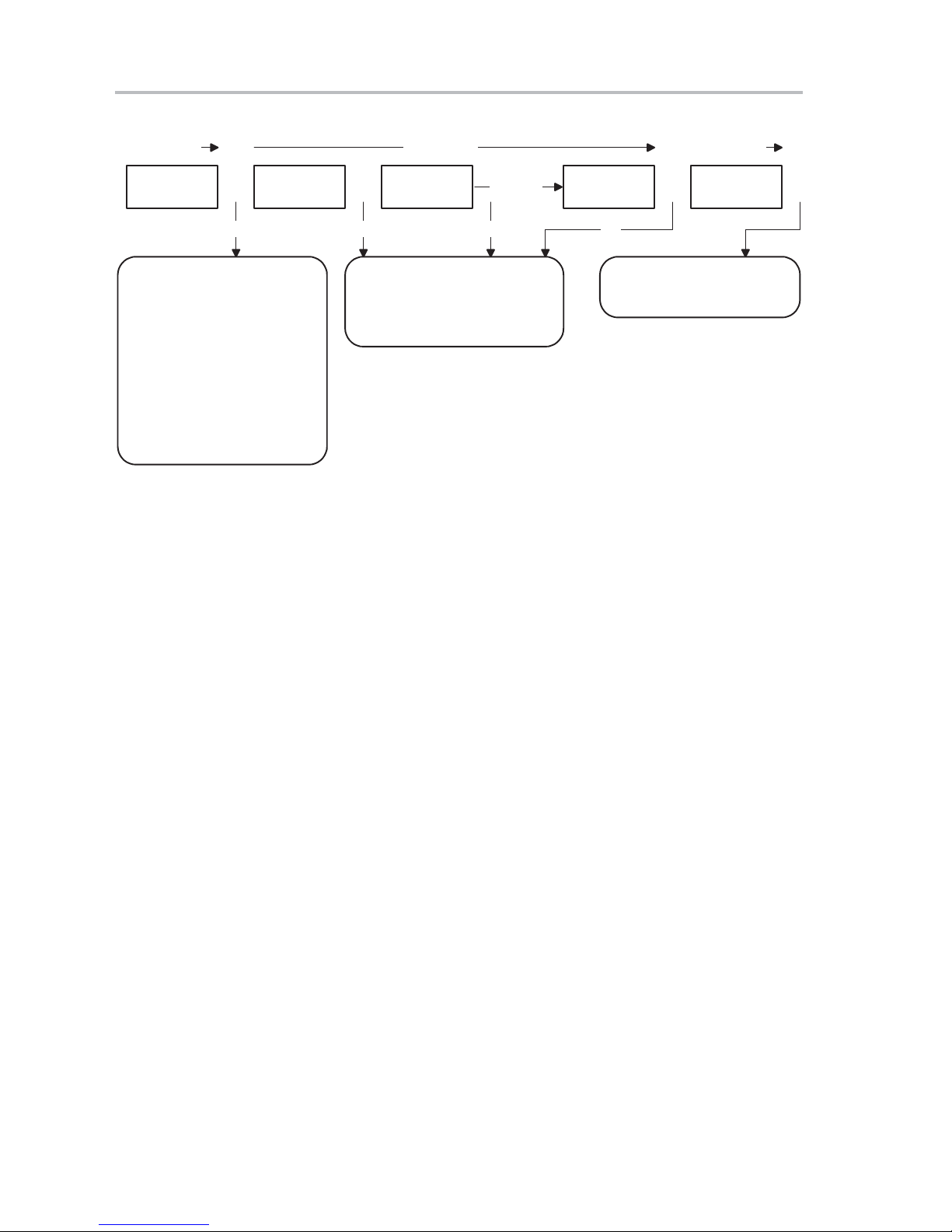
1.1 Bootcode Main Program
After power-on reset, the bootcode copies predefined USB descriptors to the
shared RAM. The first USB descriptor is the device descriptor . It describes the
embedded function class, vendor ID, product ID, etc. The second USB
descriptor is the configuration descriptor, which contains information such as
how the device is powered, the number of configurations available, type and
number of interfaces, and end-point descriptors. From these two descriptors,
Windows loads the necessary device drivers and performs pertinent actions.
Vendor and product IDs are crucial to the bootcode. Windows gets VID and
PID through the standard USB device request and then tries to match the two
IDs with its own database. If Windows finds them in the database, it loads the
corresponding device driver. If it is not able to match the IDs it provides a
prompt directing the user to provide the driver disks, which contain the INF
files.
Once the bootcode finishes copying descriptors, it looks for the EEPROM on
2
C port. If a valid signature is found, it reads the data type byte. If the data
the I
type is application code, it downloads the code to an external data space. Once
the code is loaded and the checksum is correct, bootcode releases control to
the application code. If the data contains USB device information, the
bootcode interprets the data and copies it to hub registers and to the
embedded function device descriptor, if the checksum is correct. If the data
does not contain USB device information, bootcode restores predefined
settings to the hub register and device descriptor.
After the bootcode updates the hub register and device descriptor, it sets up
for a USB transaction and connects itself to the USB. It remains there until the
host drivers download the application code. Once complete, it disconnects
from the USB and releases control to the application code. Figure 1−1
illustrates bootcode operation.
1-2
Page 11
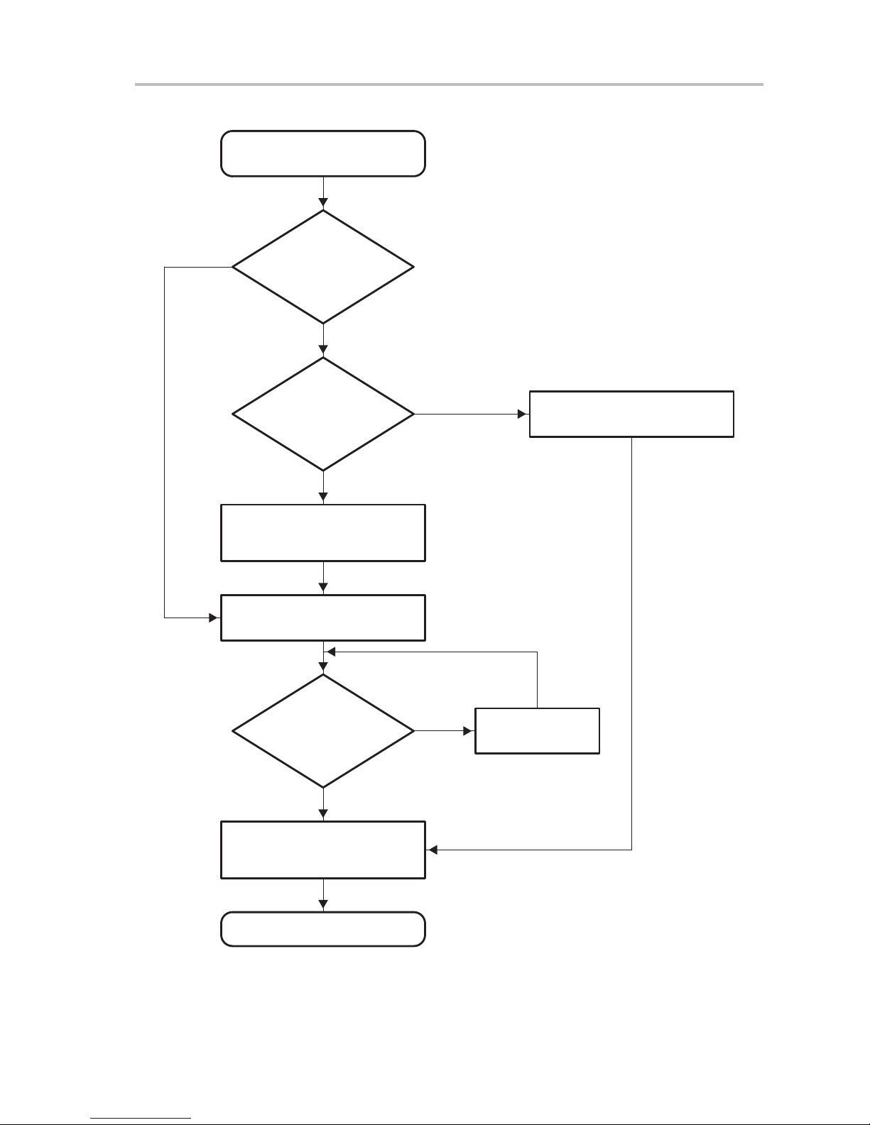
Figure 1−1.Main Routine
Copy default descriptors and
initialize necessary variables
Bootcode Main Program
No
Does EEPROM
contain valid
signature?
Yes
Does EEPROM
contain
firmware?
No
Read and copy VID and PID
from EEPROM to TUSB5052
USB data initialization
Yes
Download firmware to xdata RAM
Is firmware
loaded and ready
Disable all interrupts and switch
xdata space to code space
Run firmware
to run?
Yes
No
Load firmware
from USB
Introduction
1-3
Page 12

Interrupt Service Routine
1.2 Interrupt Service Routine
Interrupt service is generated from external interrupt 0. TUSB5052 uses this
interrupt for internal peripherals. This interrupt consists of input/output
endpoints, setup packet, I
The main service routine confirms the source of interrupt then notifies
corresponding functions. Once interrupt is performed, the main service routine
clears INTVEC registers to inform hardware that the service is complete, then
releases control back to the main program. Figure 1−2 illustrates how each
service is processed.
2
C, UART, printer port, and DMA.
1-4
Page 13
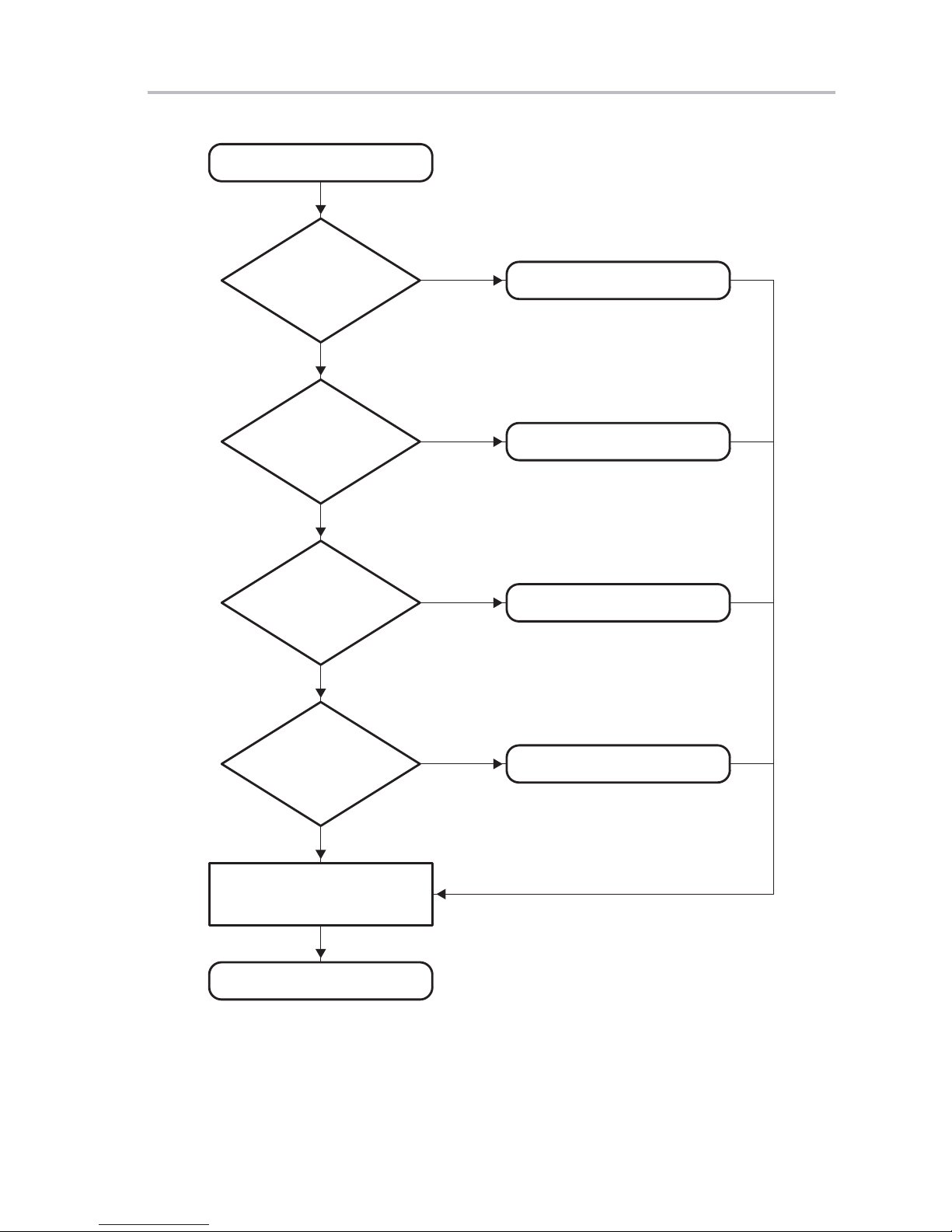
Figure 1−2.Interrupt Service Routine
Disable global interrupt
Interrupt Service Routine
Is output
endpoint 0
interrupt?
No
Is output
endpoint 1
interrupt?
No
Is input
endpoint 0
interrupt?
No
Yes
Yes
Yes
Output endpoint 0 handler
Output endpoint 1 handler
Input endpoint 0 handler
Is setup
packet received
interrupt?
No
Clear interrupt vector and
enable global interrupt
End of interrupt
Yes
Setup packet interrupt handler
Introduction
1-5
Page 14
Control (Setup) Endpoint Handler
1.3 Control (Setup) Endpoint Handler
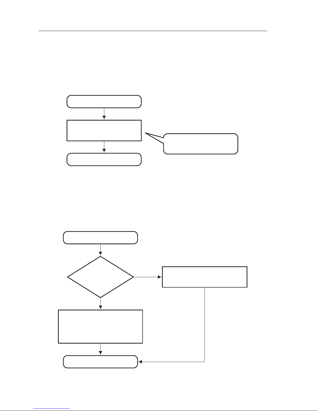
Once bootcode receives a setup packet from the host, a control packet
interrupt handler acquires control from the interrupt service routine. This
handler processes the incoming packet, performs the appropriate action, then
returns control to the interrupt service routine, as shown in Figure 1−3.
Figure 1−3.Control (Setup) Endpoint Handler
Setup packet handler
Process standard USB
request and configuration
End of interrupt
Stall IEP0 if the incoming setup
packet is illegal
1.4 Input Endpoint 0 Interrupt Handler
Figure 1−4 illustrates the process of sending data back to the host. If the last
packet is sent, the handler stalls the input endpoint, which prevents the host
from getting more data.
Figure 1−4.Input Endpoint 0 Interrupt Handler
Input endpoint 0 handler
Is this
the last
packet?
Yes
The last packet was sent. Stall IEP0.
If host asks for more data, bootcode
will stall. This scheme works fine even
in status stage because stall will be
clear once setup packet is received.
No
In data stage now, call
FillEp0TxFifoWithNextDataPacket()
routine to send out next data packet
End of interrupt
1-6
Page 15
1.5 Output Endpoint 0 Handler
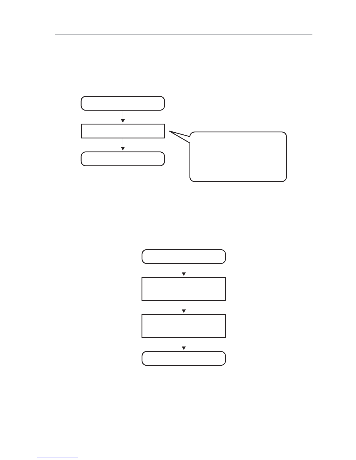
Figure 1−5 demonstrates the process bootcode uses to deal with an output
endpoint 0 interrupt. Because bootcode does not support control write with a
data stage, it merely clears the NAK bit in the handler.
Figure 1−5.Output Endpoint 0 Interrupt Handler
Output endpoint 0 handler
Clear NAK bit
End of interrupt
1.6 Output Endpoint 1 Handler
Output Endpoint 0 Handler
Bootcode does not support control
write with data stage. Therefore, this
interrupt only happens in status stage
of control read. Clear the NAK bit in
OEP0 so next OEP0 can receive next
OUT packet in status stage, or
bootcode does nothing.
The application code is downloaded from output endpoint 1, as shown in
Figure 1−6. This endpoint supports double buffered. Therefore, it switches to
the other buffer as soon as the current buffer receives data from the host.
Figure 1−6.Output Endpoint 1 Interrupt Handler
Output endpoint 1 handler
Get the size of incoming packet
from current buffer and copy
it to xdata RAM
Switch the pointer to the other
buffer. Clear the NAK in
original buffer.
End of interrupt
Introduction
1-7
Page 16

1-8
Page 17

Chapter 2
There are three types of control transfers in standard USB requests.
Figure 2−1 through Figure 2−3 and Table 2−1 and Table 2−2 demonstrate the
process bootcode uses to respond to each control transfer.
Topic Page
2.1 Control Write Transfer With Data 2-2. . . . . . . . . . . . . . . . . . . . . . . . . . . . . . .
2.2 Control Write Without Data 2-2. . . . . . . . . . . . . . . . . . . . . . . . . . . . . . . . . . . .
2.3 Control Read Transfer 2-3. . . . . . . . . . . . . . . . . . . . . . . . . . . . . . . . . . . . . . . . .
TUSB5052 USB Firmware Flow
2-1
Page 18

Control Write Transfer With Data (Bootcode does not support this)
2.1 Control Write Transfer With Data (Bootcode does not support this)
Figure 2−1.Control Write Transfer With Data
Setup stage Data stage Status stage
SETUP(0) OUT(1) OUT(0) OUT(0/1) IN(1)
INT INT INT
1. Hardware generates interrupt
to MCU.
2. Set NAK on both endpoints.
3. Set DIR bit in USBCTL to
indicate the data direction
and SIR bit to indicate setup
interrupt is being served.
4. Decode the setup packet.
5. If another setup packet
arrives, abandon this one.
6. Execute appropriate routines.
a) Clear NAK bit in OUT
endpoint.
b) Clear NAK bit in IN endpoint
for status stage.
.
1. Hardware generates interrupt to
MCU.
2. Copy data from OUT buffer.
3. Clear the NAK bit.
4. If all data has been received,
stall output endpoint.
.
More
packets
INT
1. Hardware handles this but
does not generate interrupt
to MCU.
2.2 Control Write Without Data
Table 2−1.Boot Code Response to Control Write Without Data
Control Write Without Data Action In Boot Code
Clear feature of device Stall endpoint
Clear feature of interface Stall endpoint
Clear feature of endpoint Clear stall on requested endpoint
Set feature of device Set remote wake-up feature
Set feature of interface Stall endpoint
Set feature of endpoint Stall requested endpoint
Set address Set device address
Set descriptor Stall endpoint
Set configuration Set bConfiguredFlag
Set interface Stall endpoint
Synchronization frame Stall endpoint
2-2
Page 19

Figure 2−2.Control Read Without Data
Setup stage Status stage
SETUP(0) IN(1)
INT
Control Read Transfer
1. Hardware generates interrupt
to MCU.
2. Set NAK on both endpoints.
3. Set DIR bit in USBCTL to
indicate the data direction
and SIR bit to indicate setup
interrupt is being served.
4. Decode the setup packet.
5. If another setup packet
arrives, abandon this one.
6. Execute appropriate routines.
a) Clear NAK bit in OUT
endpoint.
b) Clear NAK bit in IN endpoint
for status stage.
.
1. Hardware handles this but
does not generate interrupt
to MCU.
2.3 Control Read Transfer
Table 2−2.Boot Code Response to Control Read
Control Read Action In Boot Code
Get status of device Return remote wake-up and power status
Get status of interface No action and return zero
Get status of endpoint Return the endpoint status (stall or not)
Get descriptor of device Return device descriptor
Get descriptor of configuration Return configuration descriptor
Get descriptor of string Illegal requests, stall endpoint
Get descriptor of interface Illegal requests, stall endpoint
Get descriptor of endpoint Illegal requests, stall endpoint
Get configuration Return bConfiguredFlag value
Get interface No action and return zero
TUSB5052 USB Firmware Flow
2-3
Page 20
Control Read Transfer
Figure 2−3.Control Read
Setup stage Data stage Status stage
SETUP(0) IN(1) IN(0) IN(0/1) OUT(1)
INT INT INT
1. Hardware generates interrupt
to MCU.
2. Set NAK on both endpoints.
3. Set DIR bit in USBCTL to
indicate the data direction
and SIR bit to indicate setup
interrupt is being served.
4. Decode the setup packet.
5. If another setup packet
arrives, abandon this one.
6. Execute appropriate routines.
a) Clear NAK bit in OUT
endpoint for status stage.
b) Copy data to IN endpoint
buffer and set byte count.
.
1. Hardware generates interrupt to
MCU.
2. Copy data to IN buffer.
3. Clear the NAK bit.
4. If all data has been received,
stall IN endpoint.
.
More
packets
INT
1. Hardware handles this but
does not generate interrupt
to MCU.
2-4
Page 21

Chapter 3
Chapter 3 contains a bootcode module list with a functional description of each
bootcode module.
Topic Page
3.1 Bootcode Functional Module List 3-2. . . . . . . . . . . . . . . . . . . . . . . . . . . . . .
Function
3-1
Page 22

Bootcode Functional Module List
3.1 Bootcode Functional Module List
3.1.1 Bootcode.c File
- VOID FillEp0TxWithNextDataPacket (VOID)
This function is alerted by an interrupt service routine if there is an IN token
addressed to endpoint 0 from the host. This routine packetizes the
remainder of the data and sends one packet to the host. If the data is more
than packet size, the next packet is sent during the next interrupt
immediately after hardware receives the next IN token.
- VOID TransmitBufferOnEp0(PBYTE pbBuffer)
This checks the length and then requests the
FillEp0TxWithNextDataPacket() function to send data out.
- VOID TransmitNullResponseOnEp0(VOID)
This sends a zero length packet to the host, which is used as an
acknowledgement in the status page
- VOID Stall EndPoint0(VOID)
This stalls both input and output endpoint0, preventing the host from
sending or receiving data from endpoint0. It is sometimes used to indicate
there is an error in the transaction.
- VOID Endpoint0Control(VOID)
This supplies and executes standard USB and several vendor-specific
requests.
- VOID UsbDataInitialization(VOID)
This enables interrupts and initializes USB registers.
- VOID CopyDefaultSettings(VOID)
This copies default descriptors and initializes variables.
- VOID SetupPacketInterruptHandler(VOID)
This is called by the interrupt service routine when a setup packet is
received. This function presets some variables before it calls the
Endpoint0Control() function.
- VOID Ep0InputInterruptHandler(VOID)
This is transmitted by the interrupt service routine when an IN token is
received. If there is more data to send, it notifies the
FillEp0TxWithNextDataPacket() function to send data. Immediately
following the last packet of data is sent, it stalls the endpoint, which
prevents the host from getting data.
- VOID Ep0OutputInterruptHandler (VOID)
This is transmitted during the status stage of the control read transfer in
the bootcode. Bootcode always stalls the output endpoint due to the lack
of control write with data stage support.
- VOID Ep1OutputInterruptHandler(VOID)
This function is transmitted if there is an OUT token to endpoint 1. The first
packet of data contains the size and checksum of the application code.
Since endpoint1 is a double buffer, this routine keeps tracking the buffer
sequence.
3-2
Page 23

3.1.2 I2C.c File
Bootcode Functional Module List
Interrupt [0x03] VOID EX0_int(VOID)
-
All UMP-related interrupts are performed in this routine. It reads in vector
numbers in order to determine the type of interrupt and notifies the
appropriate functions.
- VOID main(VOID)
This is performed by the interrupt service routine when a setup packet is
received. It presets some variables then contacts the Endpoint0Control()
function.
- VOID I2CSetBusSpeed(BYTE bBusSpeed)
2
This function sets the I
C speed. If bBusSpeed is 1, the I2C bus operates
at 400 kHz.
- BYTE I2CSetMemoryType(VOID)
This function sets the I2C memory type. The ranges are from 0x01, Type
I, to 0x03, Type III device.
- BYTE I2CWaitForRead(VOID)
2
Wait routine for I
- BYTE I2CWaitForWrite(VOID)
C read
Wait routine for I2C write
3.1.3 Header.c File
- BYTE I2CRead(BYTE bDeviceAddress, WORD wAddress, WORD
wNumber, PBYTE pbDataArray)
This routine reads from one to wNumber of bytes.
- BYTE I2CWrite(BYTE bDeviceAddress, WORD wAddress, WORD
wNumber, PBYTE pbDataArray)
This routine writes from one to wNumber of bytes. It is possible that some
2
C devices have physical limitations for the number of bytes that can be
I
written each time. See the I2C device data sheet.
- BYTE headerCheckProductIDonI2C(VOID)
2
This function checks for a valid ID on the I
- BYTE headerSearchForValidHeader(VOID)
C device.
Checks for a valid signature.
- BYTE headerGetDataType(WORD wNumber)
Delivers the data type indexed by a wNumber.
- BYTE LoadFirmwareBasicFromI2C(VOID)
Loads the firmware from the I
- BYTE LoadUsbInfoBasicFromI2C(VOID)
Loads the USB data from the I
2
C device.
2
C device.
- BYTE headerProcessCurrentDataType(VOID)
- WORD headerReturnFirmwareRevision(VOID)
Checks the data type and processes the data.
This function returns the current firmware revision.
Function
3-3
Page 24

3-4
Page 25

Chapter 4
Chapter 4 lists the defaults used for hub and bootcode settings. There are
tables in each category that list the offset, field, size, and value, and provide
short descriptions for the hub, device, configuration, interface, and interrupt
endpoint1 descriptors.
Topic Page
4.1 Default Hub Settings 4-2. . . . . . . . . . . . . . . . . . . . . . . . . . . . . . . . . . . . . . . . . .
4.2 Default Bootcode Settings 4-4. . . . . . . . . . . . . . . . . . . . . . . . . . . . . . . . . . . . .
Bootcode Defaults
4-1
Page 26

Default Hub Settings
4.1 Default Hub Settings
Table 4−1.Hub Descriptor
Offset Field Size Value Description
0 bLength 1 0x09 Size of this descriptor in bytes
1 bDescriptorType 1 0x29 Device descriptor type
2 bNbrPorts 1 6 Number of downstream ports
3 wHubCharacteristics 2 0x0D [1:0] Power switching = 01 (individual)
[2] compound device = 1
[4:3] over-current protection mode = 01 (individual)
[15:5] reserved = 0
4 bPwrOn2PwrGood 1 0x32 Time (in 2ms intervals) from power on to power good
6 bHubContrCurrent 1 0x32 Maximum current requirements of the hub controller
electronics in mA
7 DeviceRemovable 1 0x60 Device removable
8 PortPwrCtrlMask 1 0xFF Port power control mask
Table 4−2.Device Descriptor
Offset Field Size Value Description
0 bLength 1 18 Size of this descriptor in bytes
1 bDescriptorType 1 1 Device descriptor type
2 BcdUSB 2 0x0110 USB spec 1.1
4 bDeviceClass 1 0xFF Vendor-specific class
5 bDeviceSubClass 1 0 None
6 bDeviceProtocol 1 0 None
7 bMaxPacketSize0 1 8 Max. packet size for endpoint zero
8 ID Vendor 2 0x0451 USB assigned vendor ID = TI
10 ID Product 2 0x2260 2 Functions and 6 ports
12 BCD Device 2 0x0100 Device release number = 1.0
14 iManufacturer 1 0 Index of string descriptor describing manufacturer
15 iProduct 1 0 Index of string descriptor describing product
16 iSerialNumber 1 0 Index of string descriptor describing device serial number
17 bNumConfigurations 1 1 Number of possible configurations
4-2
Page 27

Default Hub Settings
Table 4−3.Configuration Descriptor
Offset Field Size Value Description
0 bLlength 1 9 Size of this descriptor in bytes
1 bDescriptorType 1 2 Configuration descriptor type
2 wTotalLength 2 25 = 9 + 9 + 7 Total length of data returned for this configuration.
Includes the combined length of all descriptors
(configuration, interface, endpoint, and class- or
vendor-specific) returned for this configuration.
4 bNumInterfaces 1 1 Number of interfaces supported by this configuration
5 bConfigurationValue 1 1 Value to use as an argument to the
SetConfiguration() request to select this
configuration.
6 iConfiguration 1 0 Index of string descriptor describing this
configuration
7 bmAttributes 1 0xA0 Configuration characteristics
D7: Reserved (set to one)
D6: Self-powered
D5: Remote wake-up is supported
D4−D0: Reserved (reset to zero)
8 bMaxPower 1 0 This device consumes no power from the bus.
Table 4−4.Interface Descriptor
Offset Field Size Value Description
0 bLength 1 9 Size of this descriptor in bytes
1 bDescriptorType 1 4 Interface descriptor type
2 bInterfaceNumber 1 0 Number of interfaces. Zero-based value identifying the
index in the array of concurrent interfaces supported
by this configuration.
3 bAlternateSetting 1 0 Value used to select alternate setting for the interface
identified in the prior field
4 bNumEndpoints 1 1 Number of endpoints used by this interface (excluding
endpoint zero). If this value is zero, this interface uses
the default control pipe.
5 bInterfaceClass 1 0x09 Vendor-specific class
6 bInterfaceSubClass 1 0
7 bInterfaceProtocol 1 0
8 iInterface 1 0 Index of string descriptor describing this interface
Bootcode Defaults
4-3
Page 28

Default Bootcode Settings
Table 4−5.Interrupt Endpoint 1 Descriptor
Offset Field Size Value Description
0 bLength 1 7 Size of this descriptor in bytes
1 bDescriptorType 1 5 Endpoint descriptor type
2 bEndpointAddress 1 0x81 Bits 3−0:The endpoint number
Bit 7: Direction
0 = OUT endpoint
1 = IN endpoint
3 bmAttributes 1 3 Bits 1−0:Transfer type
10 = Bulk
11 = Interrupt
4 wMaxPacketSize 2 1 Max packet size this endpoint is capable of sending or
receiving when this configuration is selected.
6 bInterval 1 0xFF Interval for polling endpoint for data transfers, expressed
in milliseconds
4.2 Default Bootcode Settings
Table 4−6.Device Descriptor
Offset Field Size Value Description
0 bLength 1 18 Size of this descriptor in bytes
1 bDescriptorType 1 1 Device descriptor type
2 BcdUSB 2 0x0110 USB spec 1.1
4 bDeviceClass 1 0xFF Vendor-specific class
5 bDeviceSubClass 1 0 None
6 bDeviceProtocol 1 0 None
7 bMaxPacketSize0 1 8 Max packet size for endpoint zero
8 ID Vendor 2 0x0451 USB assigned vendor ID = TI
10 ID Product 2 0x5052 TI part number=TUSB5052
12 BCD Device 2 0x0100 Device release number = 1.0
14 iManufacturer 1 0 Index of string descriptor describing manufacturer
15 iProduct 1 0 Index of string descriptor describing product
16 iSerialNumber 1 0 Index of string descriptor describing device serial number
17 bNumConfigurations 1 1 Number of possible configurations
4-4
Page 29

Default Bootcode Settings
Table 4−7.Configuration Descriptor
Offset Field Size Value Description
0 bLlength 1 9 Size of this descriptor in bytes
1 bDescriptorType 1 2 Configuration descriptor type
2 wTotalLength 2 25 = 9 + 9 + 7 Total length of data returned for this configuration.
Includes the combined length of all descriptors
(configuration, interface, endpoint, and class- or
vendor-specific) returned for this configuration.
4 bNumInterfaces 1 1 Number of interfaces supported by this configuration
5 bConfigurationValue 1 1 Value to use as an argument to the
SetConfiguration() request to select this
configuration
6 iConfiguration 1 0 Index of string descriptor describing this
configuration
7 bmAttributes 1 0xC0 Configuration characteristics
D7: Reserved (set to one)
D6: Self-powered
D5: Remote wake-up is supported
D4−D0: Reserved (reset to zero)
8 bMaxPower 1 0 This device consumes no power from the bus.
Table 4−8.Interface Descriptor
Offset Field Size Value Description
0 bLength 1 9 Size of this descriptor in bytes
1 bDescriptorType 1 4 Interface descriptor type
2 bInterfaceNumber 1 0 Number of interfaces. Zero-based value identifying the
index in the array of concurrent interfaces supported by
this configuration.
3 bAlternateSetting 1 0 Value used to select alternate setting for the interface
identified in the prior field
4 bNumEndpoints 1 1 Number of endpoints used by this interface (excluding
endpoint zero). If this value is zero, this interface uses
the default control pipe.
5 bInterfaceClass 1 0xFF Vendor-specific class
6 bInterfaceSubClass 1 0
7 bInterfaceProtocol 1 0
8 iInterface 1 0 Index of string descriptor describing this interface
Bootcode Defaults
4-5
Page 30

Default Bootcode Settings
Table 4−9.Output Endpoint 1 Descriptor
Offset Field Size Value Description
0 bLength 1 7 Size of this descriptor in bytes
1 bDescriptorType 1 5 Endpoint descriptor type
2 bEndpointAddress 1 0x01 Bits 3−0:The endpoint number
Bit 7: Direction
0 = OUT endpoint
1 = IN endpoint
3 bmAttributes 1 2 Bits 1−0:Transfer type
10 = Bulk
11 = Interrupt
4 wMaxPacketSize 2 64 Maximum packet size this endpoint is capable of sending
or receiving when this configuration is selected.
6 bInterval 1 0 Interval for polling endpoint for data transfers, expressed
in milliseconds
4-6
Page 31

Chapter 5
! " #
Chapter 5 explains the header format. It describes the product signature and
descriptors and gives examples for ease of understanding. There are also
tables that list the offset, field, size, value, and description for the USB info
basic descriptor, as well as the USB info basic and firmware basic descriptor.
Topic Page
5.1 Header Format 5-2. . . . . . . . . . . . . . . . . . . . . . . . . . . . . . . . . . . . . . . . . . . . . . . .
5.2 Examples 5-3. . . . . . . . . . . . . . . . . . . . . . . . . . . . . . . . . . . . . . . . . . . . . . . . . . . .
5.3 Built-In Vendor-Specific USB Requests 5-5. . . . . . . . . . . . . . . . . . . . . . . . .
5.4 Update Header 5-6. . . . . . . . . . . . . . . . . . . . . . . . . . . . . . . . . . . . . . . . . . . . . . . .
5.5 Reboot 5-7. . . . . . . . . . . . . . . . . . . . . . . . . . . . . . . . . . . . . . . . . . . . . . . . . . . . . . .
5.6 Force Execute Firmware 5-7. . . . . . . . . . . . . . . . . . . . . . . . . . . . . . . . . . . . . . .
5.7 External Memory Read 5-7. . . . . . . . . . . . . . . . . . . . . . . . . . . . . . . . . . . . . . . .
5.8 External Memory Write 5-8. . . . . . . . . . . . . . . . . . . . . . . . . . . . . . . . . . . . . . . .
2
5.9 I
5.10 I
5.11 Internal ROM Memory Read 5-9. . . . . . . . . . . . . . . . . . . . . . . . . . . . . . . . . . . .
C Memory Read 5-8. . . . . . . . . . . . . . . . . . . . . . . . . . . . . . . . . . . . . . . . . . . . .
2
C Memory Write 5-9. . . . . . . . . . . . . . . . . . . . . . . . . . . . . . . . . . . . . . . . . . . . .
Header Format and Vendor USB Request
5-1
Page 32

Header Format
5.1 Header Format
The header is stored in various storage devices such as a ROM, parallel/serial
EEPROM, or flash ROM. The current header format routine supports only the
2
C device (serial EEPROM). A valid header contains one correct product
I
signature and one or more descriptors. The descriptor contains a descriptor
prefix and its content. Data type, size, and checksum are specified in the
descriptor prefix to describe its content. Descriptor content contains the
necessary information for bootcode to process.
5.1.1 Product Signature
There are two bytes for a signature field. They are identical to the product
number. For example, UMP (TUSB5052) is 0x5052. TUSB2136 is 0x2136.
Numerical order is LSB first.
5.1.2 Descriptor
Each descriptor contains a prefix and content. The prefix is always 4 bytes and
contains data type, size, and checksum to ensure data integrity. The descriptor
content contains information corresponding to that specified in the prefix. It
can be as small as one byte or as large as 65535 bytes. After the last
descriptor, the first byte (data type) in the descriptor prefix is zero, indicating
the end of the descriptors.
5.1.3 Descriptor Prefix
In a prefix, the first byte is the data type. This instructs the bootcode how to
parse the data in the descriptor content. The second and third bytes are the
size of the descriptor content, and the last byte is the checksum of the
descriptor content.
5.1.4 Descriptor Content
Information stored in the descriptor content is either USB information,
firmware, or another type of data. Size of the content varies from 1 to 65535
bytes.
5-2
Page 33

5.2 Examples
5.2.1 USB Info Basic Descriptor
Table 5−1 contains generic USB information for the bootcode. Once the
bootcode loads the data and verifies the checksum, it then copies information
to corresponding registers. The last byte is a zero, which indicates the end of
2
the descriptor. The descriptor easily fits into a 16-byte I
Table 5−1 and Table 5−2 are the only two supported descriptors in the
bootcode.
Table 5−1.USB Info Basic Descriptor
Offset Type Size Value Description
0 Signature0 1 0x52 FUNCTION_PID_L
1 Signature1 1 0x51 FUNCTION_PID_H
2 Data Type 1 0x01 USB info basic
3 Data Size (low byte) 1 0x09 Size of descriptor content (9 bytes total)
4 Data Size (high byte) 1 0x00
C EEPROM. Note that
Examples
5 Check Sum 1 0x80 Checksum of descriptor content
6 Bit Setting 1 0x81 Self powered and power switching
7 Vendor ID (low byte) 1 0x51 TI VID = 0x0451
8 Vendor ID (high byte) 1 0x04
9 Hub PID (low byte) 1 0x34 Hub PID = 0x1234
10 Hub PID (high byte) 1 0x12
11 Function PID (low byte) 1 0x78 Function PID = 0x5678
12 Function PID (high byte) 1 0x56
13 HUBPOTG 1 0x32 Time from power-on to power-good in 2-mA
units = 100 ms
14 HUBCURT 1 0x64 Hub current descriptor = 100 mA
15 Data Type 1 0x00 End of descriptor
Header Format and Vendor USB Request
5-3
Page 34

Examples
Table 5−2.USB Info Basic and Firmware Basic Descriptor
Offset Type Size Value Description
0 Signature0 1 0x52 FUNCTION_PID_L
1 Signature1 1 0x51 FUNCTION_PID_H
2 Data type 1 0x01 USB info basic
3 Data size (low byte) 1 0x08 Size of descriptor content (8 bytes total)
4 Data size (high byte) 1 0x00
5 Check sum 1 0x45 Checksum of descriptor content
6 Bit setting 1 0x80 Bus-powered and overcurrent protection
7 Vendor ID (low byte) 1 0xAA Hub and function VID = 0x55AA
8 Vendor ID (high byte) 1 0x55
9 Hub PID (low byte) 1 0x20 Hub PID = 0x1020
0x0A Hub PID (high byte) 1 0x10
0x0B Function PID (low byte) 1 0x22 Function PID = 0x1122
0x0C Function PID (high byte) 1 0x11
0x0D HUBPOTG 1 0x10 Time from power-on to power-good in 2-mA
units = 32 ms
0x0E HUBCURT 1 0x20 Hub current descriptor = 32 mA
0x0F Data type 1 0x02 Firmware basic
0x10 Data size (low byte) 1 0x25 Size of descriptor content
0x11 Data size (high byte) 1 0x10 The size is 0x1025 bytes
0x12 Check sum 1 XX
†
Checksum of descriptor content
0x13 Firmware rev. (low byte) 1 0x10 Revision = 1.1
0x14 Firmware rev. (high byte) 1 0x10
0x15 Firmware starts here 0x1023 Firmware binary code
0x1038 Data type 1 0x00 End of descriptor
†
Checksum of firmware binary code and firmware revision
5-4
Page 35

Built-In Vendor-Specific USB Requests
5.3 Built-In Vendor-Specific USB Requests
5.3.1 Get Bootcode Status
bmRequestType USB_REQ_TYPE_DEVICE |
USB_REQ_TYPE_VENDOR |
USB_REQ_TYPE_IN
bRequest BTC_GET_BOOTCODE_STATUS 0x80
wValue None 0x0000
wIndex None 0x0000
wLength Size of the status 0x0004
Data Bootcode status data 0xNNNN
Bootcode returns the 4-byte status value. Currently, the 4 bytes are not
defined.
5.3.2 Execute Firmware
bmRequestType USB_REQ_TYPE_DEVICE |
USB_REQ_TYPE_VENDOR |
USB_REQ_TYPE_OUT
†
1100 0000b
0100 0000b
bRequest BTC_EXECUTE_FIRMWARE 0x81
wValue None 0x0000
wIndex None 0x0000
wLength None 0x0004
Data None 0xNNNN
This command requests bootcode to execute the downloaded firmware. If the
checksum is correct, bootcode disconnects from the USB, then releases
control to the firmware or it stalls the command.
5.3.3 Get Firmware Revision
bmRequestType USB_REQ_TYPE_DEVICE |
bRequest BTC_EXECUTE_FIRMWARE 0x82
wValue None 0x0000
wIndex
wLength None 0x0002
Data None 0xNNNN
1100 0000b
USB_REQ_TYPE_VENDOR |
USB_REQ_TYPE_IN
None 0x0000
(specified in the header)
Bootcode returns the 2-byte value described in the header file.
†Vendor specific requests are for internal testing only. TI does not assure their performance.
Header Format and Vendor USB Request
5-5
Page 36

Update Header
5.3.4 Prepare for Header Update
bmRequestType USB_REQ_TYPE_DEVICE |
USB_REQ_TYPE_VENDOR |
USB_REQ_TYPE_OUT
bRequest BTC_PRE_UPDATE_HEADER 0x83
wValue None 0x0000
wIndex None 0x0000
wLength None 0x0000
Data None
0100 0000b
This command tells bootcode that pending data downloaded through the
output endpoint 1 is a header file rather than firmware.
The following procedures update the header file.
1) The host driver sends a BTC_PRE_UPDATE_HEADER request informing bootcode that the pending data from the output endpoint 1 is a header
file.
2) The host driver transmits a header file through OEP1.
3) After the header file is downloaded, the host driver sends a BTC_UPDATE_HEADER request, which allows bootcode to update the header
file. The update to the host driver is not immediate.
5.4 Update Header
4) The host driver sends the last request, BTC_REBOOT, which prompts
bootcode to start over with an updated PID and VID.
bmRequestType USB_REQ_TYPE_DEVICE |
USB_REQ_TYPE_VENDOR |
USB_REQ_TYPE_OUT
bRequest BTC_UPDATE_HEADER 0x84
wValue HI: Block size
LO: Wait time in ms
wIndex None 0x0000
wLength None 0x0000
Data None
0100 0000b
0xNNNN
This command instructs the bootcode to update the header to I2C EEPROM.
Block size is the size of page write and wait time is the time between each page
2
write. Be aware that different I
C EEPROMs may have dif ferent physical page
boundaries. If the block size is too large, it might possibly cross the physical
page boundary and, as a result, that data could be lost or overwrite the data
address 0x0000.
5-6
Page 37

5.5 Reboot
Reboot
bmRequestType USB_REQ_TYPE_DEVICE |
bRequest BTC_REBOOT 0x85
wValue None 0x0000
wIndex None 0x0000
wLength None 0x0000
Data None
This command forces bootcode to reboot (start over).
bRequest values from 0x86 to 0x8E are reserved.
5.6 Force Execute Firmware
bmRequestType USB_REQ_TYPE_DEVICE |
bRequest BTC_FORCE_EXECUTE_FIRMWARE 0x8F
wValue None 0x0000
0100 0000b
USB_REQ_TYPE_VENDOR |
USB_REQ_TYPE_OUT
0100 0000b
USB_REQ_TYPE_VENDOR |
USB_REQ_TYPE_OUT
wIndex None 0x0000
wLength None 0x0000
Data None
This command instructs bootcode to execute the downloaded firmware
unconditionally.
5.7 External Memory Read
bmRequestType USB_REQ_TYPE_DEVICE |
bRequest BTC_EXTERNAL_MEMORY_READ 0x90
wValue None 0x0000
wIndex Data address 0xNNNN
wLength One byte 0x0001
Data Byte in the specified address 0xNN
0100 0000b
USB_REQ_TYPE_VENDOR |
USB_REQ_TYPE_IN
(from 0x0000 to
0xFFFF)
Bootcode returns the content of the specified address.
Header Format and Vendor USB Request
5-7
Page 38

External Memory Write
5.8 External Memory Write
bmRequestType USB_REQ_TYPE_DEVICE |
bRequest BTC_EXTERNAL_MEMORY_WRITE 0x91
wValue HI: 0x00
wIndex Data address 0xNNNN
wLength None 0x0000
Data None
This command instructs bootcode to write data to the specified address.
5.9 I2C Memory Read
bmRequestType USB_REQ_TYPE_DEVICE |
bRequest BTC_I2C_MEMORY_READ 0x92
wValue HI: I2C Device Number
0100 0000b
USB_REQ_TYPE_VENDOR |
USB_REQ_TYPE_OUT
0x00NN
LO: Data
(from 0x0000 to
0xFFFF)
0100 0000b
USB_REQ_TYPE_VENDOR |
USB_REQ_TYPE_IN
0xNNNN
LO: Memory Type BIt[0−1] and
Speed Bit[7]
wIndex Data address 0xNNNN
(from 0x0000 to
0xFFFF)
wLength One byte 0x0001
Data Byte in the specified address 0xNNN
Bootcode returns the content of the specified address in I2C EEPROM.
In the wValue field, the I
2
C device number is from 0x00 to 0x07 in the high field.
Memory type is from 0x01 to 0x03 for CAT I to CAT III devices. If bit 7 of bValueL
is set, 400 kHz is used. If bit 7 of bValueL is not set, 100 kHz is used. This
2
request is also used to set the device number and speed before an I
C write
request.
5-8
Page 39

5.10 I2C Memory Write
I2C Memory Write
bmRequestType USB_REQ_TYPE_DEVICE |
bRequest BTC_I2C_MEMORY_WRITE 0x93
wValue HI: I2C device number
wIndex Data address 0xNNNN
wLength None 0x0000
Data None
This command instructs the bootcode to write data to the specified address.
2
C device number is specified in the bValueH field.
The I
5.11 Internal ROM Memory Read
bmRequestType USB_REQ_TYPE_DEVICE |
bRequest BTC_INTERNAL_ROM_MEMORY_READ 0x94
0100 0000b
USB_REQ_TYPE_VENDOR |
USB_REQ_TYPE_OUT
0xNNNN
LO: Data
(from 0x0000 to
0xFFFF)
0100 0000b
USB_REQ_TYPE_VENDOR |
USB_REQ_TYPE_OUT
wValue None 0xNNNN
wIndex Data address 0xNNNN
(from 0x0000 to
0xFFFF)
wLength One byte 0x0001
Data Byte in the specified address 0xNN
Bootcode returns the byte (binary code of the bootcode) of the specified
address in ROM.
Header Format and Vendor USB Request
5-9
Page 40

5-10
Page 41

Chapter 6
$
%
Chapter 6 addresses programing considerations and includes a short section
on USB requests and a table on vector interrupt values and sources. The
remaining portion comprises the bootcode file list.
Topic Page
6.1 Programming Considerations 6-2. . . . . . . . . . . . . . . . . . . . . . . . . . . . . . . . . .
6.2 File List 6-4. . . . . . . . . . . . . . . . . . . . . . . . . . . . . . . . . . . . . . . . . . . . . . . . . . . . . .
2
6.3 header.c I
6.4 tusb5052.h UMP-Related Header File 6-38. . . . . . . . . . . . . . . . . . . . . . . .
6.5 usb.h USB-Related Header File 6-52. . . . . . . . . . . . . . . . . . . . . . . . . . . . .
6.6 types.h Type Definition Header File 6-55. . . . . . . . . . . . . . . . . . . . . . . . . .
6.7 i2c.h I
6.8 header.h I
C Header Routines 6-32. . . . . . . . . . . . . . . . . . . . . . . . . . . . . . .
2
C-Related Header File 6-56. . . . . . . . . . . . . . . . . . . . . . . . . . . . . . .
2
C Header-Process-Related Header File 6-58. . . . . . . . . . . .
Programming Considerations and Bootcode File List
6-1
Page 42

Programming Considerations
6.1 Programming Considerations
6.1.1 USB Requests
For each USB request the firmware follows these steps, which ensure proper
hardware operation.
1) Firmware first sets NAK bit on both input data endpoint 0 and output data
endpoint 0, clears the interrupt sources, then clears the VECINT register.
For example, for a setup packet, the firmware must clear the USBSTA_SETUP bit by writing a 1 to the bit of the register.
2) Firmware determines the direction of the request by checking the MSB of
the bmRequestType field. It then sets the USBCTL_DIR bit.
3) Firmware sets USBCTL_SIR, indicating it is providing the current request.
4) Firmware decodes the command and serves the request.
6.1.2 Interrupt Handling Routine
Table 6−1.Vector Interrupt Values and Sources
G[3:0]
(Hex)
0 0 00 No Interrupt No source
1 0 10 Not used
1 1 12 Output endpoint 1 VECINT register
1 2 14 Output endpoint 2 VECINT register
1 3 16 Output endpoint 3 VECINT register
1 4 18 Output endpoint 4 VECINT register
1 5 1A Output endpoint 5 VECINT register
1 6 1C Output endpoint 6 VECINT register
1 7 1E Output endpoint 7 VECINT register
2 0 20 Not used
2 1 22 Input endpoint 1 VECINT register
2 2 24 Input endpoint 2 VECINT register
2 3 26 Input endpoint 3 VECINT register
2 4 28 Input endpoint 4 VECINT register
2 5 2A Input endpoint 5 VECINT register
2 6 2C Input endpoint 6 VECINT register
2 7 2E Input endpoint 7 VECINT register
3 0 30 STPOW packet received USBSTA/VECINT† registers
3 1 32 SETUP packet received USBSTA/VECINT registers
3 2 34 Reserved USBSTA/VECINT registers
3 3 36 Reserved USBSTA/VECINT registers
3 4 38 RESR interrupt USBSTA/VECINT registers
3 5 3A SUSR interrupt USBSTA/VECINT registers
3 6 3C RSTR interrupt USBSTA/VECINT registers
3 7 3E WAKEUP interrupt USBSTA/VECINT registers
†
If interrupt sources are more than two, firmware always clears the VECINT register last.
I[2:0]
(Hex)
VECTOR
(Hex)
Interrupt Source Interrupt Source should be
cleared
6-2
Page 43

Table 6−1. Vector Interrupt Values and Sources (Continued)
G[3:0]
(Hex)
4 0 40 I2C TXE interrupt I2CSTA/VECINT registers
4 1 42 I2C RXF interrupt I2CSTA/VECINT registers
4 2 44 Input endpoint 0 VECINT register
4 3 46 Output endpoint 0 VECINT register
4 4−7 48−4E Not used
5 0 50 UART1 status interrupt LSR/VECINT registers
5 1 52 UART1 modem interrupt LSR/VECINT registers
5 2 54 UART2 status interrupt MSR/VECINT registers
5 3 56 UART2 modem interrupt MSR/VECINT registers
5 4−7 58−5E Not used
6 0 60 UART1 RxF interrupt LSR/VECINT registers
6 1 62 UART1 TxE interrupt LSR/VECINT registers
6 2 64 UART2 RxF interrupt LSR/VECINT Registers
6 3 66 UART2 TxE interrupt LSR/VECINT registers
6 4−7 68−6E Not used
7 0 70 PP: RxF interrupt PPSTA/VECINT registers
7 1 72 PP: TxE interrupt PPSTA/VECINT registers
7 2 74 PP: FALT interrupt PPSTA/VECINT registers
7 3 76 PP: ACK interrupt PPSTA/VECINT registers
7 4 78 PP: PER interrupt PPSTA/VECINT registers
7 5−7 7A−7E Not used
8 0 80 DMA1 interrupt DMACSR/VECINT registers
8 1 82 DMA2 interrupt DMACSR/VECINT registers
8 2 84 DMA3 interrupt DMACSR/VECINT registers
8 3 86 DMA4 interrupt DMACSR/VECINT registers
8 4 88 DMA5 interrupt DMACSR/VECINT registers
8 5−7 8A−8E Not used
9−15 X 90−FE Not used
I[2:0]
(Hex)
VECTOR
(Hex)
Interrupt Source Interrupt Source should be
Programming Considerations
cleared
Programming Considerations and Bootcode File List
6-3
Page 44

File List
6.2 File List
6.2.1 Bootcode.c Main Program
/*−−−−−−−−−−−−−−−−−−−−−−−−−−−−−−−−−−−−−−−−−−−−−−−−−−−−−−−−−−−−−−−−−−−−−−+
| Texas Instruments |
| Bootcode |
+−−−−−−−−−−−−−−−−−−−−−−−−−−−−−−−−−−−−−−−−−−−−−−−−−−−−−−−−−−−−−−−−−−−−−−−+
| Source: bootcode.c, v 1.0 2000/01/26 16:45:55 |
| Author: Horng−Ming Lobo Tai lobotai@ti.com |
| |
| For more information, contact |
| Lobo Tai |
| Texas Instruments |
| 12500 TI Blvd, MS 8761 |
| Dallas, TX 75243 |
| USA |
| Tel 214−480−3145 |
| Fax 214−480−3443 |
| |
| External EEPROM Format
| |
| Offset
| 0 Signature0 1 0x52, FUNCTION_PID_L |
| 1 Signature1 1 0x51, FUNCTION_PID_H |
| 2 Data Type 1 0x00 = End |
| 0x01 = USB Info Basic |
| 0x02 = Application Code |
| 0x03..0xEF Reserved |
| 0xff = Reserved for Extended Data |
| 3 Data Size 2 Size of Data |
| 9 for TUSB5052 & TUSB2136 Usb Info|
| 5 Check Sum 1 Check Sum of Data Section |
| 6 Bit Setting 1 Bit 0: Bus/self power in bUSBCRL |
| Bit 7: PWRSW |
| 7 VID 2 Vendor ID |
| 9 PID hub 2 Product ID for hub |
| 11 PID device 2 Product ID for bootrom |
| 13 HUBPOTG 1 Time from power-on to power-good |
| 14 HUBCURT 1 HUB Current descriptor register |
| |
| The following examples is for application code |
| 15 Data Type 1 0x00 = End |
| 0x02 = Application Code |
| 16 Data Size 2 Size of Data Section |
| 18 Check Sum 1 Check Sum of Data Section |
| 19 App. Rev. 2 Application Code Revision |
| |
| 21 Application Code Starts here... |
| Logs: |
WHEN WHAT |
| WHO
| HMT 20000126 born |
| HMT 20000301 add PWRSW and HUBPOTG |
| HMT 20000331 Set address request (check illigeal address) |
Type Size Value & Remark |
|
6-4
Page 45

| HMT 20000517 modified header and added bus power support |
| HMT 20000525 added HUBCURT |
| modified header |
+−−−−−−−−−−−−−−−−−−−−−−−−−−−−−−−−−−−−−−−−−−−−−−−−−−−−−−−−−−−−−−−−−−−−−−*/
#include <io51.h> // 8051 sfr definition
#include <stdio.h>
#include <stdlib.h>
#include ”types.h” // Basic Type declarations
#include ”usb.h” // USB−specific Data Structures
#include ”i2c.h”
#include ”tusb5052.h”
#include ”delay.h”
#include ”header.h”
#include ”bootcode.h”
#ifdef SIMULATION
#include ”gpio.h”
#endif
/*−−−−−−−−−−−−−−−−−−−−−−−−−−−−−−−−−−−−−−−−−−−−−−−−−−−−−−−−−−−−−−−−−−−−−−+
| Constant Definition |
+−−−−−−−−−−−−−−−−−−−−−−−−−−−−−−−−−−−−−−−−−−−−−−−−−−−−−−−−−−−−−−−−−−−−−−*/
// for double buffer pointer
#define X_BUFFER 0
#define Y_BUFFER 1
BYTE code abromDeviceDescriptor[SIZEOF_DEVICE_DESCRIPTOR] = {
SIZEOF_DEVICE_DESCRIPTOR, // Length of this descriptor (12h bytes)
DESC_TYPE_DEVICE, // Type code of this descriptor (01h)
0x10,0x01, // Release of USB spec (Rev 1.1)
0xff, // Device’s base class code−vendor specific
0, // Device’s sub class code
0, // Device’s protocol type code
EP0_MAX_PACKET_SIZE, // End point 0’s max packet size = 8
HUB_VID_L,HUB_VID_H, // Vendor ID for device, TI=0x0451
FUNCTION_PID_L,FUNCTION_PID_H, // Product ID for device, TUSB5052
0x00,0x01, // Revision level of device, Rev=1.0
0, // Index of manufacturer name string desc
0, // Index of product name string desc
0, // Index of serial number string desc
1 // Number of configurations supported
};
BYTE code abromConfigurationDescriptorGroup[SIZEOF_BOOTCODE_CONFIG_DESC_GROUP] =
{
// Configuration Descriptor, size=0x09
SIZEOF_CONFIG_DESCRIPTOR, // bLength
DESC_TYPE_CONFIG, // bDescriptorType
SIZEOF_BOOTCODE_CONFIG_DESC_GROUP, 0x00, // wTotalLength
0x01, // bNumInterfaces
0x01, // bConfigurationValue
0x00, // iConfiguration
0x80, // bmAttributes, bus−powered hub
0x32, // Max. Power Consumption at 2mA unit
// Interface Descriptor, size = 0x09
SIZEOF_INTERFACE_DESCRIPTOR, // bLength
DESC_TYPE_INTERFACE, // bDescriptorType
0x00, // bInterfaceNumber
File List
Programming Considerations and Bootcode File List
6-5
Page 46

File List
0x00, // bAlternateSetting
1, // bNumEndpoints
0xFF, // bInterfaceClass − vendor−specific
0, // bInterfaceSubClass, zero for hub
0, // bInterfaceProtocol
0x00, // iInterface
// Endpoint Descriptor, size = 0x07 for OEP1
SIZEOF_ENDPOINT_DESCRIPTOR, // bLength
DESC_TYPE_ENDPOINT, // bDescriptorType
0x01 , // bEndpointAddress; bit7=1 for IN, bits 3−0=1 for ep1
EP_DESC_ATTR_TYPE_BULK, // bmAttributes, bulk transfer
0x40, 0x00, // wMaxPacketSize, 64 bytes
0x00 // bInterval
};
// Global Memory Map
#pragma memory = idata
BYTE bEp0TxBytesRemaining; // For endpoint zero transmitter only
// Holds count of bytes remaining to be
// transmitted by endpoint 0. A value
// of 0 means that a 0−length data packet
// A value of 0xFF means that transfer
// is complete.
BYTE bHostAskMoreDataThanAvailable;
// If the host ask more data then TUSB2136 has
// It sends one zero−length packet
// if the asked lenght is a multiple of
// max. size of endpoint 0
BYTE bConfiguredFlag; // Set to 1 when USB device has been
// configured, set to 0 when unconfigured
PBYTE pbEp0Buffer; // A pointer to end point 0
WORD wCurrentFirmwareAddress; // for firmware downloading
WORD wFirmwareLength;
BYTE bFirmwareChecksum;
BYTE bRAMChecksum;
BOOL bExecuteFirmware; // flag set by USB request to run the firmware
BOOL bRAMChecksumCorrect;
BOOL bCurrentBuffer;
BYTE abBootCodeStatus[4];
extern WORD wCurrentUploadPointer; // in header.c
extern BYTE bi2cDeviceAddress; // in header.c
#pragma memory = default
/*−−−−−−−−−−−−−−−−−−−−−−−−−−−−−−−−−−−−−−−−−−−−−−−−−−−−−−−−−−−−−−−−−−−−−−−−−−−+
| TUSB5052 Register Structure Definition |
+−−−−−−−−−−−−−−−−−−−−−−−−−−−−−−−−−−−−−−−−−−−−−−−−−−−−−−−−−−−−−−−−−−−−−−−−−−−*/
#pragma memory = dataseg(TUSB5052_SETUPPACKET_SEG) // 0xff00
tDEVICE_REQUEST tSetupPacket;
#pragma memory = default
#pragma memory = dataseg(TUSB5052_EP0_EDB_SEG) // 0xff80
tEDB0 tEndPoint0DescriptorBlock;
#pragma memory = default
#pragma memory = dataseg(TUSB5052_IEP_EDB_SEG) // 0xff48
tEDB tInputEndPointDescriptorBlock[1];
#pragma memory = default
#pragma memory = dataseg(TUSB5052_OEP_EDB_SEG) // 0xf940
6-6
Page 47

tEDB tOutputEndPointDescriptorBlock[1];
#pragma memory = default
#pragma memory = dataseg(TUSB5052_IEP0BUFFER_SEG) // 0xfef8
BYTE abIEP0Buffer[EP0_MAX_PACKET_SIZE];
#pragma memory = default
#pragma memory = dataseg(TUSB5052_OEP0BUFFER_SEG) // 0xfef0
BYTE abOEP0Buffer[EP0_MAX_PACKET_SIZE];
#pragma memory = default
#pragma memory = dataseg(TUSB5052_DESC_SEG) // 0xfc00
BYTE abDeviceDescriptor[SIZEOF_DEVICE_DESCRIPTOR];
BYTE abConfigurationDescriptorGroup[SIZEOF_BOOTCODE_CONFIG_DESC_GROUP];
#pragma memory = default
#pragma memory = dataseg(TUSB5052_OEP1_X_BUFFER_SEG)
BYTE abXBufferAddress[EP_MAX_PACKET_SIZE];
#pragma memory = default
#pragma memory = dataseg(TUSB5052_OEP1_Y_BUFFER_SEG)
BYTE abYBufferAddress[EP_MAX_PACKET_SIZE];
#pragma memory = default
#pragma memory = dataseg(TUSB5052_EXTERNAL_RAM_SEG) // 0x0000
BYTE abDownloadFirmware[1024*16];
#pragma memory = default
/*−−−−−−−−−−−−−−−−−−−−−−−−−−−−−−−−−−−−−−−−−−−−−−−−−−−−−−−−−−−−−−−−−−−−−−−−−−−+
| Sub−routines go here... |
+−−−−−−−−−−−−−−−−−−−−−−−−−−−−−−−−−−−−−−−−−−−−−−−−−−−−−−−−−−−−−−−−−−−−−−−−−−−*/
//−−−−−−−−−−−−−−−−−−−−−−−−−−−−−−−−−−−−−−−−−−−−−−−−−−−−−−−−−−−−−−−−−−−−−−−−−−−−
VOID FillEp0TxWithNextDataPacket(VOID)
{
BYTE bPacketSize,bIndex;
// First check if there are bytes remaining to be transferred
if (bEp0TxBytesRemaining != 0xFF)
{
if (bEp0TxBytesRemaining > EP0_MAX_PACKET_SIZE)
{
// More bytes are remaining than are capable of fitting in one packet
bPacketSize = EP0_MAX_PACKET_SIZE;
bEp0TxBytesRemaining −= EP0_MAX_PACKET_SIZE;
// there are more IN Stage
}
else if (bEp0TxBytesRemaining < EP0_MAX_PACKET_SIZE)
{
// The remaining data fits in one packet.
// This case properly handles bEp0TxBytesRemaining == 0
bPacketSize = bEp0TxBytesRemaining;
bEp0TxBytesRemaining = 0xFF; // No more data need to be Txed
}
else //bEp0TxBytesRemaining == EP0_MAX_PACKET_SIZE
{
bPacketSize = EP0_MAX_PACKET_SIZE;
if(bHostAskMoreDataThanAvailable == TRUE) bEp0TxBytesRemaining = 0;
else bEp0TxBytesRemaining = 0xFF;
}
for (bIndex=0; bIndex<bPacketSize; bIndex++)
abIEP0Buffer[bIndex] = *pbEp0Buffer++;
tEndPoint0DescriptorBlock.bIEPBCNT = bPacketSize & EPBCT_BYTECNT_MASK;
File List
Programming Considerations and Bootcode File List
6-7
Page 48

File List
}
}
//−−−−−−−−−−−−−−−−−−−−−−−−−−−−−−−−−−−−−−−−−−−−−−−−−−−−−−−−−−−−−−−−−−−−−−−−−−−−
VOID TransmitBufferOnEp0(PBYTE pbBuffer)
{
pbEp0Buffer = pbBuffer;
// Limit wLength to FEh
if (tSetupPacket.bLengthH != 0){
tSetupPacket.bLengthH = 0;
tSetupPacket.bLengthL = 0xFE;
}
// Limit transfer size to wLength if needed
// this prevent USB device sending ’more than require’ data back to the host
if (bEp0TxBytesRemaining > tSetupPacket.bLengthL)
bEp0TxBytesRemaining = tSetupPacket.bLengthL;
if(bEp0TxBytesRemaining < tSetupPacket.bLengthL)
bHostAskMoreDataThanAvailable = TRUE;
else bHostAskMoreDataThanAvailable = FALSE;
FillEp0TxWithNextDataPacket();
}
//−−−−−−−−−−−−−−−−−−−−−−−−−−−−−−−−−−−−−−−−−−−−−−−−−−−−−−−−−−−−−−−−−−−−−−−−−−−−
VOID TransmitNullResponseOnEp0 (VOID)
{
pbEp0Buffer = NULL; // to indicate a partial packet
bEp0TxBytesRemaining = 0; // or ACK during standard USB request
FillEp0TxWithNextDataPacket();
}
//−−−−−−−−−−−−−−−−−−−−−−−−−−−−−−−−−−−−−−−−−−−−−−−−−−−−−−−−−−−−−−−−−−−−−−−−−−−−
VOID StallEndPoint0(VOID)
{
tEndPoint0DescriptorBlock.bIEPCNFG |= EPCNF_STALL;
tEndPoint0DescriptorBlock.bOEPCNFG |= EPCNF_STALL;
}
//−−−−−−−−−−−−−−−−−−−−−−−−−−−−−−−−−−−−−−−−−−−−−−−−−−−−−−−−−−−−−−−−−−−−−−−−−−−−
VOID Endpoint0Control(VOID)
{
BYTE bTemp;
WORD wIndex;
BYTE abReturnBuffer[3];
BOOL InTransaction;
// copy the MSB of bmRequestType to DIR bit of USBCTL
if((tSetupPacket.bmRequestType & USB_REQ_TYPE_INPUT) != 0x00){
InTransaction = TRUE;
bUSBCTL |= USBCTL_DIR;
}else{
InTransaction = FALSE;
bUSBCTL &= ~USBCTL_DIR;
}
// Set setup bit in USB control register
bUSBCTL |= USBCTL_SIR; // on bit 1
// clear endpoint stall here
// If hardware in setup stage(hardware clears stall) but firmware still
// in data stage(stall at the last packet), sometimes hardware clears stall
// but firmware later on stall again. This causes problem in the new transfer
6-8
Page 49

File List
// while firmware still in the previous transfer.
tEndPoint0DescriptorBlock.bIEPCNFG &= ~EPCNF_STALL;
tEndPoint0DescriptorBlock.bOEPCNFG &= ~EPCNF_STALL;
abReturnBuffer[0] = 0;
abReturnBuffer[1] = 0;
abReturnBuffer[2] = 0;
switch(tSetupPacket.bmRequestType & USB_REQ_TYPE_MASK)
{
case USB_REQ_TYPE_STANDARD:
// check if high byte of wIndex is p184 of spec 1.1
if((tSetupPacket.bIndexH != 0x00)){
StallEndPoint0();
return;
}
switch (tSetupPacket.bRequest)
{
case USB_REQ_GET_STATUS:
// check if it is a read command
if(InTransaction == FALSE){
// control read but direction is OUT
StallEndPoint0();
return;
}
// check if wValue is zero
if((tSetupPacket.bValueH != 0x00) || (tSetupPacket.bValueL != 0x00)){
StallEndPoint0();
return;
}
// check if bLengthL = 0x02, wLength = 0x00
if((tSetupPacket.bLengthL != 0x02) || (tSetupPacket.bLengthH != 0x00)){
StallEndPoint0();
return;
}else tEndPoint0DescriptorBlock.bOEPBCNT = 0x00; // for status stage
switch (tSetupPacket.bmRequestType & USB_REQ_TYPE_RECIP_MASK)
{
case USB_REQ_TYPE_DEVICE:
// check if wIndex is zero
if(tSetupPacket.bIndexL != 0x00){
StallEndPoint0();
return;
}
// Return self power status, no remote wakeup
bEp0TxBytesRemaining = 2;
if((bUSBCTL & USBCTL_SELF) == USBCTL_SELF)
abReturnBuffer[0] = DEVICE_STATUS_SELF_POWER;
TransmitBufferOnEp0((PBYTE)abReturnBuffer);
break;
case USB_REQ_TYPE_INTERFACE: // return all zeros
if(tSetupPacket.bIndexL != 0x00){
StallEndPoint0();
return;
}
bEp0TxBytesRemaining = 2;
TransmitBufferOnEp0 ((PBYTE)abReturnBuffer);
Programming Considerations and Bootcode File List
6-9
Page 50

File List
break;
case USB_REQ_TYPE_ENDPOINT:
// Endpoint number is in low byte of wIndex
bTemp = tSetupPacket.bIndexL & EP_DESC_ADDR_EP_NUM;
if(bTemp==0){ // EndPoint 0
if(tSetupPacket.bIndexL & EP_DESC_ADDR_DIR_IN)
// input endpoint
abReturnBuffer[0] = (BYTE)
(tEndPoint0DescriptorBlock.bIEPCNFG & EPCNF_STALL);
else
// output endpoint
abReturnBuffer[0] = (BYTE)
(tEndPoint0DescriptorBlock.bOEPCNFG & EPCNF_STALL);
}else{
if(bTemp > MAX_ENDPOINT_NUMBER){
StallEndPoint0();
return;
}
bTemp−−;
if(tSetupPacket.bIndexL & EP_DESC_ADDR_DIR_IN)
// input endpoint
abReturnBuffer[0] = (BYTE)
(tInputEndPointDescriptorBlock[bTemp].bEPCNF &
EPCNF_STALL);
else
// output endpoint
abReturnBuffer[0] = (BYTE)
(tOutputEndPointDescriptorBlock[bTemp].bEPCNF &
EPCNF_STALL);
}
abReturnBuffer[0] >>= 3; // STALL is on bit 3
bEp0TxBytesRemaining = 2;
TransmitBufferOnEp0 ((PBYTE)abReturnBuffer);
break;
case USB_REQ_TYPE_OTHER:
default:
StallEndPoint0();
break;
}
break;
case USB_REQ_CLEAR_FEATURE:
// check if it is a write command
if(InTransaction == TRUE){
// control write but direction is IN
StallEndPoint0();
return;
}
// check if bLengthL = 0x00, wLength = 0x00
if((tSetupPacket.bLengthL != 0x00) || (tSetupPacket.bLengthH != 0x00)){
StallEndPoint0();
return;
}
// control write, stall output endpoint 0
// wLength should be 0 in all cases
tEndPoint0DescriptorBlock.bOEPCNFG |= EPCNF_STALL;
switch (tSetupPacket.bmRequestType & USB_REQ_TYPE_RECIP_MASK)
6-10
Page 51

File List
{
case USB_REQ_TYPE_ENDPOINT:
// Endpoint number is in low byte of wIndex
if(tSetupPacket.bValueL == FEATURE_ENDPOINT_STALL){
bTemp = tSetupPacket.bIndexL & EP_DESC_ADDR_EP_NUM;
if(bTemp){
if(bTemp > MAX_ENDPOINT_NUMBER){
StallEndPoint0();
return;
}
bTemp−−; // EP is from EP1 to EP7 while C
language start from 0
if(tSetupPacket.bIndexL & EP_DESC_ADDR_DIR_IN)
// input endpoint
tInputEndPointDescriptorBlock[bTemp].bEPCNF &=
~EPCNF_STALL;
else
// output endpoint
tOutputEndPointDescriptorBlock[bTemp].bEPCNF &=
~EPCNF_STALL;
}else{ // EP0
// clear both in and out stall
// no reason to have one stall while the other is
not for EP0
tEndPoint0DescriptorBlock.bIEPCNFG &= ~EPCNF_STALL;
tEndPoint0DescriptorBlock.bOEPCNFG &= ~EPCNF_STALL;
}
}else{
StallEndPoint0();
return;
}
TransmitNullResponseOnEp0();
break;
case USB_REQ_TYPE_DEVICE:
case USB_REQ_TYPE_INTERFACE:
case USB_REQ_TYPE_OTHER:
default:
StallEndPoint0();
break;
}
break;
case USB_REQ_SET_FEATURE:
// check if bLengthL = 0x00, wLength = 0x00
if((tSetupPacket.bLengthL != 0x00) || (tSetupPacket.bLengthH != 0x00)){
StallEndPoint0();
return;
}
// check if it is a write command
if(InTransaction == TRUE){
// control write but direction is IN
StallEndPoint0();
return;
}
// control write, stall output endpoint 0
// wLength should be 0 in all cases
Programming Considerations and Bootcode File List
6-11
Page 52

File List
tEndPoint0DescriptorBlock.bOEPCNFG |= EPCNF_STALL;
switch (tSetupPacket.bmRequestType & USB_REQ_TYPE_RECIP_MASK)
{
// Feature selector is in wValue
case USB_REQ_TYPE_ENDPOINT:
// Endpoint number is in low byte of wIndex
if (tSetupPacket.bValueL == FEATURE_ENDPOINT_STALL){
bTemp = tSetupPacket.bIndexL & EP_DESC_ADDR_EP_NUM;
// Ignore EP0 STALL, no reaon to have EP0 STALL
if(bTemp){ // other endpoints
if(bTemp > MAX_ENDPOINT_NUMBER){
StallEndPoint0();
return;
}
bTemp−−; // EP is from EP1 to EP3 while C
language start from 0
if(tSetupPacket.bIndexL & EP_DESC_ADDR_DIR_IN)
// input endpoint
tInputEndPointDescriptorBlock[bTemp].bEPCNF |=
EPCNF_STALL;
else
// output endpoint
tOutputEndPointDescriptorBlock[bTemp].bEPCNF |=
EPCNF_STALL;
}
}else {
StallEndPoint0();
return;
}
TransmitNullResponseOnEp0();
break;
case USB_REQ_TYPE_DEVICE:
case USB_REQ_TYPE_INTERFACE:
case USB_REQ_TYPE_OTHER:
default:
StallEndPoint0();
break;
}
break;
case USB_REQ_SET_ADDRESS:
// check if recipient is device
if((tSetupPacket.bmRequestType & USB_REQ_TYPE_RECIP_MASK) !=
USB_REQ_TYPE_DEVICE){
StallEndPoint0();
return;
}
// check if bLengthL = 0x00, wLength = 0x00
if((tSetupPacket.bLengthL != 0x00) || (tSetupPacket.bLengthH != 0x00)){
StallEndPoint0();
return;
}
// check if wIndex is zero
if(tSetupPacket.bIndexL != 0x00){
StallEndPoint0();
return;
6-12
Page 53

File List
}
// check if it is a write command
if(InTransaction == TRUE){
// control write but direction is IN
StallEndPoint0();
return;
}
// control write, stall output endpoint 0
// wLength should be 0 in all cases
tEndPoint0DescriptorBlock.bOEPCNFG |= EPCNF_STALL;
if(tSetupPacket.bValueL < 128){
bFUNADR = tSetupPacket.bValueL ;
TransmitNullResponseOnEp0();
}else StallEndPoint0();
break;
case USB_REQ_GET_DESCRIPTOR:
// check if recipient is device
if((tSetupPacket.bmRequestType & USB_REQ_TYPE_RECIP_MASK) !=
USB_REQ_TYPE_DEVICE){
StallEndPoint0();
return;
}
// check if it is a read command
if(InTransaction == FALSE){
// control read but direction is OUT
StallEndPoint0();
return;
}
// check if wLength = 0
if((tSetupPacket.bLengthL | tSetupPacket.bLengthH)==0x00){
// control read but wLength = 0
StallEndPoint0();
return;
}else tEndPoint0DescriptorBlock.bOEPBCNT = 0x00;
switch (tSetupPacket.bValueH)
{
case DESC_TYPE_DEVICE:
bEp0TxBytesRemaining = SIZEOF_DEVICE_DESCRIPTOR;
TransmitBufferOnEp0((PBYTE)&abDeviceDescriptor);
break;
case DESC_TYPE_CONFIG:
bEp0TxBytesRemaining = SIZEOF_BOOTCODE_CONFIG_DESC_GROUP;
TransmitBufferOnEp0((PBYTE)&abConfigurationDescriptorGroup);
break;
case DESC_TYPE_STRING:
case DESC_TYPE_INTERFACE:
case DESC_TYPE_ENDPOINT:
default:
StallEndPoint0();
return;
}
break;
case USB_REQ_GET_CONFIGURATION:
// check if recipient is device
Programming Considerations and Bootcode File List
6-13
Page 54

File List
if((tSetupPacket.bmRequestType & USB_REQ_TYPE_RECIP_MASK) !=
USB_REQ_TYPE_DEVICE){
StallEndPoint0();
return;
}
// check if it is a read command
if(InTransaction == FALSE){
// control read but direction is OUT
StallEndPoint0();
return;
}
// check if wIndex = 0x00
if(tSetupPacket.bIndexL != 0x00){
StallEndPoint0();
return;
}
// check if wValue = 0x00
if((tSetupPacket.bValueL != 0x00) || (tSetupPacket.bValueH != 0x00)){
StallEndPoint0();
return;
}
// check if wLength = 1
if((tSetupPacket.bLengthL != 0x01) || (tSetupPacket.bLengthH!=0x00)){
StallEndPoint0();
return;
}else tEndPoint0DescriptorBlock.bOEPBCNT = 0x00;
bEp0TxBytesRemaining = 1;
TransmitBufferOnEp0 ((PBYTE)&bConfiguredFlag);
break;
case USB_REQ_SET_CONFIGURATION:
// check if recipient is device
if((tSetupPacket.bmRequestType & USB_REQ_TYPE_RECIP_MASK) !=
USB_REQ_TYPE_DEVICE){
StallEndPoint0();
return;
}
// check if it is a write command
if(InTransaction == TRUE){
// control write but direction is IN
StallEndPoint0();
return;
}
// check if wIndex = 0x00
if(tSetupPacket.bIndexL != 0x00){
StallEndPoint0();
return;
}
// check if wLength = 0x00
if((tSetupPacket.bLengthH != 0x00) || (tSetupPacket.bLengthL != 0x00)){
StallEndPoint0();
return;
}
// control write, stall output endpoint 0
// wLength should be 0 in all cases
tEndPoint0DescriptorBlock.bOEPCNFG |= EPCNF_STALL;
6-14
Page 55

File List
// check if bValueL is greater than 1
if(tSetupPacket.bValueL > 0x01){
StallEndPoint0();
return;
}
bConfiguredFlag = tSetupPacket.bValueL;
TransmitNullResponseOnEp0();
return;
case USB_REQ_GET_INTERFACE:
// check if recipient is interface
if((tSetupPacket.bmRequestType & USB_REQ_TYPE_RECIP_MASK) !=
USB_REQ_TYPE_INTERFACE){
StallEndPoint0();
return;
}
if(tSetupPacket.bIndexL != 0x00){
StallEndPoint0();
return;
}
// check if it is a read command
if(InTransaction == FALSE){
// control read but direction is OUT
StallEndPoint0();
return;
}
// check if wValue = 0x00
if((tSetupPacket.bValueL != 0x00) || (tSetupPacket.bValueH != 0x00)){
StallEndPoint0();
return;
}
// check if wLength = 1
if((tSetupPacket.bLengthL != 0x01) || (tSetupPacket.bLengthH != 0x00)){
StallEndPoint0();
return;
}else tEndPoint0DescriptorBlock.bOEPBCNT = 0x00;
bEp0TxBytesRemaining = 1;
TransmitBufferOnEp0 ((PBYTE)abReturnBuffer);
break;
case USB_REQ_SET_INTERFACE:
// check if recipient is interface
if((tSetupPacket.bmRequestType & USB_REQ_TYPE_RECIP_MASK) !=
USB_REQ_TYPE_INTERFACE){
StallEndPoint0();
return;
}
if(tSetupPacket.bIndexL != 0x00){
StallEndPoint0();
return;
}
// check if it is a write command
if(InTransaction == TRUE){
// control write but direction is IN
StallEndPoint0();
return;
}
Programming Considerations and Bootcode File List
6-15
Page 56

File List
// check if wLength = 0x00
if((tSetupPacket.bLengthL != 0x00) || (tSetupPacket.bLengthH != 0x00)){
StallEndPoint0();
return;
}
// check if wValue = 0x00
if((tSetupPacket.bValueL != 0x00) || (tSetupPacket.bValueH != 0x00)){
StallEndPoint0();
return;
}
// control write, stall output endpoint 0
// wLength should be 0 in all cases
tEndPoint0DescriptorBlock.bOEPCNFG |= EPCNF_STALL;
TransmitNullResponseOnEp0();
return;
case USB_REQ_SET_DESCRIPTOR:
case USB_REQ_SYNCH_FRAME:
default:
// stall input and output endpoint 0
StallEndPoint0();
return;
}
break;
case USB_REQ_TYPE_VENDOR:
// check if recipient is device
if((tSetupPacket.bmRequestType & USB_REQ_TYPE_RECIP_MASK) !=
USB_REQ_TYPE_DEVICE){
StallEndPoint0();
return;
}
// general requests related to fiemware
switch(tSetupPacket.bRequest){
case 0x80: // get bootcode status
bEp0TxBytesRemaining = 4;
TransmitBufferOnEp0 ((PBYTE)abBootCodeStatus);
break;
case 0x81: // run firmware
if(bFirmwareChecksum == bRAMChecksum){
bExecuteFirmware = TRUE;
bRAMChecksumCorrect = TRUE;
TransmitNullResponseOnEp0();
}else StallEndPoint0();
break;
case 0x82: // Get firmware version
wIndex = headerReturnFirmwareRevision();
abReturnBuffer[0] = (BYTE)(wIndex & 0x00ff);
abReturnBuffer[1] = (BYTE)(wIndex >> 8);
bEp0TxBytesRemaining = 2;
TransmitBufferOnEp0 ((PBYTE)abReturnBuffer);
break;
case 0x83: // prepare for update header
wCurrentUploadPointer = 0x0000;
wCurrentFirmwareAddress = 0x0000;
bRAMChecksum = 0x00;
6-16
Page 57

File List
wFirmwareLength = 0xffff; // skip firmware length/checksum
TransmitNullResponseOnEp0();
break;
case 0x84: // Update Header
// bIndexH(BlockSize)
// bIndexL(wait time)
// wValueH(device type)
// wValueL(device id)
i2cSetMemoryType(tSetupPacket.bValueH);
bi2cDeviceAddress = tSetupPacket.bValueL;
if(UpdateHeader(wCurrentFirmwareAddress,
tSetupPacket.bIndexH,tSetupPacket.bIndexL)==ERROR)
StallEndPoint0();
else TransmitNullResponseOnEp0();
break;
case 0x85: // reboot
bExecuteFirmware = TRUE;
TransmitNullResponseOnEp0();
break;
case 0x8f: // run firmware (forced run)
bExecuteFirmware = TRUE;
bRAMChecksumCorrect = TRUE;
TransmitNullResponseOnEp0();
break;
// for memory access for advanced feature
case 0x90: // external memory read
wIndex = (WORD)(tSetupPacket.bIndexH << 0x08) +
(WORD)tSetupPacket.bIndexL;
abReturnBuffer[0] = *(pbExternalRAM+wIndex);
bEp0TxBytesRemaining = 1;
TransmitBufferOnEp0 ((PBYTE)abReturnBuffer);
break;
case 0x91: // external memory write
wIndex = (WORD)(tSetupPacket.bIndexH << 0x08) |
(WORD)tSetupPacket.bIndexL;
// address write, bValueL(data)
*(pbExternalRAM+wIndex) = tSetupPacket.bValueL;
TransmitNullResponseOnEp0();
break;
case 0x92: // i2c memory read
wIndex = (WORD)(tSetupPacket.bIndexH << 0x08) +
(WORD)tSetupPacket.bIndexL;
// bValueL : memory type (cat 1, cat 2, or cat 3), bit7:speed
// bValueH : device number (A2−A0)
// wIndex : Address
i2cSetMemoryType((tSetupPacket.bValueL & MASK_I2C_DEVICE_ADDRESS));
if((tSetupPacket.bValueL & 0x80) != 0x00) i2cSetBusSpeed(I2C_400KHZ);
else i2cSetBusSpeed(I2C_100KHZ);
if(i2cRead(tSetupPacket.bValueH &
MASK_I2C_DEVICE_ADDRESS,wIndex,1,&abReturnBuffer[0])==NO_ERROR){
bEp0TxBytesRemaining = 1;
TransmitBufferOnEp0 ((PBYTE)abReturnBuffer);
}else StallEndPoint0();
Programming Considerations and Bootcode File List
6-17
Page 58

File List
break;
case 0x93: // i2c memory write
wIndex = (WORD)(tSetupPacket.bIndexH << 0x08) +
(WORD)tSetupPacket.bIndexL;
// address write, bValueL(data), bValueH(device number)
abReturnBuffer[0] = tSetupPacket.bValueL;
if(i2cWrite(tSetupPacket.bValueH &
MASK_I2C_DEVICE_ADDRESS,wIndex,1,&abReturnBuffer[0])== NO_ERROR){
DelaymSecond(0x05);
TransmitNullResponseOnEp0();
}else StallEndPoint0();
break;
case 0x94: // internal ROM memory read
wIndex = (WORD)(tSetupPacket.bIndexH << 0x08) +
(WORD)tSetupPacket.bIndexL;
abReturnBuffer[0] = *(pbInternalROM+wIndex);
bEp0TxBytesRemaining = 1;
TransmitBufferOnEp0 ((PBYTE)abReturnBuffer);
break;
#ifdef SIMULATION
// for internal testing only! The host driver should NOT make these
requests
case 0xe0: // get current checksum
abReturnBuffer[0] = bRAMChecksum;
bEp0TxBytesRemaining = 1;
TransmitBufferOnEp0 ((PBYTE)abReturnBuffer);
break;
case 0xe1: // get downloaded size
abReturnBuffer[0] = (BYTE)(wCurrentFirmwareAddress & 0x00ff);
abReturnBuffer[1] = (BYTE)((wCurrentFirmwareAddress & 0xff00) >> 8);
bEp0TxBytesRemaining = 2;
TransmitBufferOnEp0 ((PBYTE)abReturnBuffer);
break;
case 0xe2: // set download size and checksum
// wValue(firmware size)
// bIndexL(checksum)
wCurrentFirmwareAddress = (WORD)(tSetupPacket.bValueH << 0x08) +
(WORD)tSetupPacket.bValueL;
bRAMChecksum = tSetupPacket.bIndexL;
TransmitNullResponseOnEp0();
break;
case 0xF0: // ROM Address Dump
wIndex = (WORD)(tSetupPacket.bIndexH << 0x08) +
(WORD)tSetupPacket.bIndexL;
lcdRomDump(wIndex,4);
TransmitNullResponseOnEp0();
break;
case 0xF1: // External Memory Dump
wIndex = (WORD)(tSetupPacket.bIndexH << 0x08) +
(WORD)tSetupPacket.bIndexL;
lcdExternalMemoryDump(wIndex,4);
TransmitNullResponseOnEp0();
break;
case 0xF2: // I2C Dump
// wIndexH(Data Address)
// wValueH(device type)
6-18
Page 59

File List
// wValueL(device id)
i2cSetMemoryType(tSetupPacket.bValueH);
bi2cDeviceAddress = tSetupPacket.bValueL;
wIndex = (WORD)(tSetupPacket.bIndexH << 0x08) +
(WORD)tSetupPacket.bIndexL;
lcdI2cDump(wIndex,4);
TransmitNullResponseOnEp0();
break;
#endif
default:
// stall input and output endpoint 0
StallEndPoint0();
return;
}
break;
case USB_REQ_TYPE_CLASS:
default:
StallEndPoint0();
return;
}
}
//−−−−−−−−−−−−−−−−−−−−−−−−−−−−−−−−−−−−−−−−−−−−−−−−−−−−−−−−−−−−−−−−−−−−−−−−−−−−
VOID UsbDataInitialization(VOID)
{
bFUNADR = 0x00; // no device address
bEp0TxBytesRemaining = 0xff; // no data remaining
pbEp0Buffer = NULL;
bConfiguredFlag = 0x00; // device unconfigured
bExecuteFirmware = FALSE; // a flag set by USB request
// before bootocode hands over
// control to firmware
bCurrentBuffer = X_BUFFER; // for firmware download
bRAMChecksumCorrect = FALSE;
wCurrentFirmwareAddress = 0x0000;
bRAMChecksum = 0x00;
wFirmwareLength = 0x0000;
// enable endpoint 0 interrupt
tEndPoint0DescriptorBlock.bIEPCNFG = EPCNF_USBIE | EPCNF_UBME;
tEndPoint0DescriptorBlock.bOEPCNFG = EPCNF_USBIE | EPCNF_UBME;
// enable endpoint 1 interrupt
tOutputEndPointDescriptorBlock[0].bEPCNF = EPCNF_USBIE | EPCNF_UBME | EPCNF_DBUF;
tOutputEndPointDescriptorBlock[0].bEPBBAX = (BYTE)(OEP1_X_BUFFER_ADDRESS >> 3 &
0x00ff);
tOutputEndPointDescriptorBlock[0].bEPBCTX = 0x0000;
tOutputEndPointDescriptorBlock[0].bEPBBAY = (BYTE)(OEP1_Y_BUFFER_ADDRESS >> 3 &
0x00ff);
tOutputEndPointDescriptorBlock[0].bEPBCTY = 0x0000;
tOutputEndPointDescriptorBlock[0].bEPSIZXY = EP_MAX_PACKET_SIZE;
// Enable the USB−specific Interrupts; SETUP, RESET and STPOW
bUSBMSK = USBMSK_STPOW | USBMSK_SETUP | USBMSK_RSTR;
// disable all four downstream port
bHUBCNF1 = 0x00;
// enable port 6 and keep power switch setting
bHUBCNF2 |= HUBCNF2_P6_EN;
}
Programming Considerations and Bootcode File List
6-19
Page 60

File List
//−−−−−−−−−−−−−−−−−−−−−−−−−−−−−−−−−−−−−−−−−−−−−−−−−−−−−−−−−−−−−−−−−−−−−−−−−−−−
VOID CopyDefaultSettings(VOID)
{
BYTE bTemp;
// clear out status bits
abBootCodeStatus[0] = 0x00;
abBootCodeStatus[1] = 0x00;
abBootCodeStatus[2] = 0x00;
abBootCodeStatus[3] = 0x00;
// disconnect from USB
bUSBCTL = 0x00;
// Disable endpoints EP1
tOutputEndPointDescriptorBlock[0].bEPCNF = 0x00;
// set default values for hub
bHUBPIDL = HUB_PID_L;
bHUBPIDH = HUB_PID_H;
bHUBVIDL = HUB_VID_L;
bHUBVIDH = HUB_VID_H;
// copy descriptor to allocated address
// copy device and configuration descriptor to external memory
for(bTemp=0;bTemp<SIZEOF_DEVICE_DESCRIPTOR;bTemp++)
abDeviceDescriptor[bTemp] = abromDeviceDescriptor[bTemp];
for(bTemp=0;bTemp<SIZEOF_BOOTCODE_CONFIG_DESC_GROUP;bTemp++)
abConfigurationDescriptorGroup[bTemp] =
abromConfigurationDescriptorGroup[bTemp];
// set power wait time for the hub
bHUBPOTG = HUBPOTG_100MS; // 100 ms from power−on to power−good
// set power rating for the hub
bHUBCURT = HUBCURT_100MA; // 100 ms from power−on to power−good
// set i2c speed
i2cSetBusSpeed(I2C_100KHZ);
}
/*−−−−−−−−−−−−−−−−−−−−−−−−−−−−−−−−−−−−−−−−−−−−−−−−−−−−−−−−−−−−−−−−−−−−−−−−−−−+
| Interrupt Sub−routines |
+−−−−−−−−−−−−−−−−−−−−−−−−−−−−−−−−−−−−−−−−−−−−−−−−−−−−−−−−−−−−−−−−−−−−−−−−−−−*/
//−−−−−−−−−−−−−−−−−−−−−−−−−−−−−−−−−−−−−−−−−−−−−−−−−−−−−−−−−−−−−−−−−−−−−−−−−−−−
VOID SetupPacketInterruptHandler(VOID)
{
bEp0TxBytesRemaining = 0xFF; // setup packet received successfully
pbEp0Buffer = NULL; // clear remaining to be transmitted on endpoint 0
Endpoint0Control();
}
//−−−−−−−−−−−−−−−−−−−−−−−−−−−−−−−−−−−−−−−−−−−−−−−−−−−−−−−−−−−−−−−−−−−−−−−−−−−−
VOID Ep0InputInterruptHandler(VOID)
{
// check if the last packet sent
tEndPoint0DescriptorBlock.bOEPBCNT = 0x00; // is set by the hardware
if(bEp0TxBytesRemaining == 0xff){
// last packet just sent, stall input endpoint 0
// so error conditions would occurs when the host asks more data
tEndPoint0DescriptorBlock.bIEPCNFG |= EPCNF_STALL;
}else FillEp0TxWithNextDataPacket();
}
6-20
Page 61

//−−−−−−−−−−−−−−−−−−−−−−−−−−−−−−−−−−−−−−−−−−−−−−−−−−−−−−−−−−−−−−−−−−−−−−−−−−−−
VOID Ep0OutputInterruptHandler(VOID)
{
// happened only in status stage
// Bootrom doesn’t handle data stage of control write.
// stall for any OUT, this is cleared in the setup stage.
tEndPoint0DescriptorBlock.bOEPCNFG |= EPCNF_STALL;
}
//−−−−−−−−−−−−−−−−−−−−−−−−−−−−−−−−−−−−−−−−−−−−−−−−−−−−−−−−−−−−−−−−−−−−−−−−−−−−
VOID Ep1OutputInterruptHandler(VOID)
{
BYTE bTemp,bSize,bCode;
// check if it is the first packet
if(wFirmwareLength == 0x0000){
wFirmwareLength = (WORD)abXBufferAddress[0];
wFirmwareLength += (WORD)(abXBufferAddress[1] << 8);
bFirmwareChecksum = abXBufferAddress[2];
bSize = tOutputEndPointDescriptorBlock[0].bEPBCTX & EPBCT_BYTECNT_MASK;
for(bTemp=3;bTemp<bSize;bTemp++){
bCode = abXBufferAddress[bTemp];
abDownloadFirmware[wCurrentFirmwareAddress] = bCode;
bRAMChecksum += bCode;
wCurrentFirmwareAddress++;
}
bCurrentBuffer = Y_BUFFER;
// clear NAK bit
tOutputEndPointDescriptorBlock[0].bEPBCTX = 0x00;
}else{
if(bCurrentBuffer == X_BUFFER){
// firgure out the size of packet
bSize = tOutputEndPointDescriptorBlock[0].bEPBCTX & EPBCT_BYTECNT_MASK;
for(bTemp=0;bTemp<bSize;bTemp++){
bCode = abXBufferAddress[bTemp];
abDownloadFirmware[wCurrentFirmwareAddress] = bCode;
bRAMChecksum += bCode;
wCurrentFirmwareAddress++;
}
bCurrentBuffer = Y_BUFFER;
// clear NAK bit
tOutputEndPointDescriptorBlock[0].bEPBCTX = 0x00;
}else{ // data in y buffer
// firgure out the size of packet
bSize = tOutputEndPointDescriptorBlock[0].bEPBCTY & EPBCT_BYTECNT_MASK;
for(bTemp=0;bTemp<bSize;bTemp++){
bCode = abYBufferAddress[bTemp];
abDownloadFirmware[wCurrentFirmwareAddress] = bCode;
bRAMChecksum += bCode;
wCurrentFirmwareAddress++;
}
bCurrentBuffer = X_BUFFER;
// clear NAK bit
tOutputEndPointDescriptorBlock[0].bEPBCTY = 0x00;
}
}
File List
Programming Considerations and Bootcode File List
6-21
Page 62

File List
// check if firmware is ready
if((WORD)wCurrentFirmwareAddress >= wFirmwareLength){
// check is checksum is correct
if(bRAMChecksum == bFirmwareChecksum){
#ifdef SIMULATION
lcdPutString(”USB Checksum Correct!”);
DelaymSecond(2000);
#endif
bRAMChecksumCorrect = TRUE;
bExecuteFirmware = TRUE;
}else{
#ifdef SIMULATION
lcdPutString(”USB Checksum Incorrect!”);
DelaymSecond(2000);
#endif
bRAMChecksumCorrect = FALSE;
}
}
}
/*−−−−−−−−−−−−−−−−−−−−−−−−−−−−−−−−−−−−−−−−−−−−−−−−−−−−−−−−−−−−−−−−−−−−−−−−−−−+
| Interrupt Service Routines |
+−−−−−−−−−−−−−−−−−−−−−−−−−−−−−−−−−−−−−−−−−−−−−−−−−−−−−−−−−−−−−−−−−−−−−−−−−−−*/
interrupt [0x03] void EX0_int(void) // External Interrupt 0
{
EA = DISABLE; // Disable any further interrupts
// always clear the interrupt source first and then bVECINT
switch (bVECINT){ // Identify Interrupt ID
case VECINT_OUTPUT_ENDPOINT0:
bVECINT = 0x00;
Ep0OutputInterruptHandler();
break;
case VECINT_INPUT_ENDPOINT0:
bVECINT = 0x00;
Ep0InputInterruptHandler();
break;
case VECINT_OUTPUT_ENDPOINT1:
bVECINT = 0x00;
Ep1OutputInterruptHandler();
break;
case VECINT_STPOW_PACKET_RECEIVED:
SetupPacketInterruptHandler();
// clear setup packet flag (clear source first)
bUSBSTA = USBSTA_STPOW;
bVECINT = 0x00;
break;
case VECINT_SETUP_PACKET_RECEIVED:
SetupPacketInterruptHandler();
// clear setup packet flag
bUSBSTA = USBSTA_SETUP;
bVECINT = 0x00;
break;
case VECINT_RSTR_INTERRUPT:
UsbDataInitialization();
6-22
Page 63

// clear reset flag
bUSBSTA = USBSTA_RSTR;
bVECINT = 0x00;
break;
default:break; // unknown interrupt ID
}
EA = ENABLE; // Enable the interrupts again
}
//−−−−−−−−−−−−−−−−−−−−−−−−−−−−−−−−−−−−−−−−−−−−−−−−−−−−−−−−−−−−−−−−−−−−−−−−−−−−
#ifdef SIMULATION
BYTE code abTestHeader[16]
= { 0x52,0x51, // product ID
0x01, // Data Type (USB Info)
0x09,0x00, // Data Size (9 bytes)
0x80, // checksum
0x81, // bit setting (slef and switching)
0x51,0x04, // VID
0x34,0x12, // PID for hub
0x78,0x56, // PID for function
0x32, // for HUBPOTG
0x64, // for HUBCURT
0x00 // End of descriptor
};
BYTE code abNullHeader[8] = {0x55,0x55,0x55,0x55,0x55,0x55,0x55,0x55};
#endif
//−−−−−−−−−−−−−−−−−−−−−−−−−−−−−−−−−−−−−−−−−−−−−−−−−−−−−−−−−−−−−−−−−−−−−−−−−−−−
VOID main(VOID)
{
#ifdef SIMULATION
WORD wAddress;
for(wAddress = 0; wAddress < 0x8000; wAddress++)
abDownloadFirmware[wAddress] = 0x00;
gpioInitialization();
lcdPutString(”UMP BootSim ”);
// clear i2c
// for(wAddress=0x0100; wAddress < 0x200;wAddress+=8){
// i2cWrite(0x00,wAddress,8,abNullHeader);
// DelaymSecond(20);
// }
i2cSetBusSpeed(I2C_100KHZ);
i2cSetMemoryType(I2C_CATEGORY_3);
for(wAddress=0;wAddress<16;wAddress++){
// i2cWrite(0x00,wAddress,1,&abTestHeader[wAddress]);
DelaymSecond(20);
}
// lcdI2cDump(0x0000,4);
// ledPutChar(0x01,0x64);
// while(1);
#endif
CopyDefaultSettings();
UsbDataInitialization();
// partial support due to memory size
if(headerSearchForValidHeader() == DATA_MEDIUM_HEADER_I2C){
if(headerGetDataType(1) == DATA_TYPE_HEADER_HUB_INFO_BASIC){
File List
Programming Considerations and Bootcode File List
6-23
Page 64

File List
if(headerProcessCurrentDataType()==MSG_HEADER_NO_ERROR){
#ifdef SIMULATION
lcdPutString(”usbinfo”);
#endif
bRAMChecksumCorrect = TRUE;
}
}
if(headerGetDataType(2) == DATA_TYPE_HEADER_FIRMWARE_BASIC){
if(headerProcessCurrentDataType()==MSG_HEADER_NO_ERROR){
#ifdef SIMULATION
lcdPutString(”firmware”);
#endif
bRAMChecksumCorrect = TRUE;
bExecuteFirmware = TRUE;
}
}
}
if(bExecuteFirmware == FALSE){
// use default value
EA = ENABLE; // Enable global interrupt
EX0 = ENABLE; // Enable interrupt 0
bUSBCTL |= USBCTL_CONT; // connect to upstream port
#ifdef SIMULATION
lcdPutString(”Connecting”);
bUSBCTL |= 0xc0;
#endif
while(bExecuteFirmware == FALSE);
}
// Disable all interrupts
EA = DISABLE; // disable global interrupt
// disconnection
bUSBCTL = USBCTL_FRSTE;
// map xdata to code space if checksum correct
// now application code is in code space
if(bRAMChecksumCorrect == TRUE){
#ifdef SIMULATION
lcdPutStringXY(0,2,”Set Shadow Bit”);
DelaymSecond(4000);
#endif
bROMS |= ROMS_SDW;
}else{
#ifdef SIMULATION
lcdPutStringXY(0,2,”Shadow Bit Not Set!”);
DelaymSecond(4000);
#endif
}
(*(void(*)(void))0x0000)(); // run firmware now
}
//−−−−−−−−−−−−−−−−−−−−−−−−−−−−− Cut along the line −−−−−−−−−−−−−−−−−−−−−−−−−−−−
6-24
Page 65

6.2.2 I2C.c I2C Routines
/*−−−−−−−−−−−−−−−−−−−−−−−−−−−−−−−−−−−−−−−−−−−−−−−−−−−−−−−−−−−−−−−−−−−−−−−−−−−−+
| Texas Instruments |
| I2C |
+−−−−−−−−−−−−−−−−−−−−−−−−−−−−−−−−−−−−−−−−−−−−−−−−−−−−−−−−−−−−−−−−−−−−−−−−−−−−−+
| Source: i2c.c, v 1.0 99/01/28 11:00:36 |
| Author: Horng−Ming Lobo Tai lobotai@ti.com |
| Header: (none) |
| |
| For more information, contact |
| Lobo Tai |
| Texas Instruments |
| 12500 TI Blvd, MS 8761 |
| Dallas, TX 75243 |
| USA |
| Tel 214−480−3145 |
| Fax 214−480−3443 |
| |
| Notes: |
WHEN WHAT |
| WHO
| HMT 19990128 born |
| HMT 19990414 add the following functions (SiCore’s format) |
| HMT 19990423 modified i2cWaitForRead & i2cWaitForWrite |
| to write ’1’ clear and removed eUMP functions |
| HMT 19990611 fixed bug in i2cRead when bNumber is 1 |
| HMT 19991124 port to usb keyboard |
| HMT 20000122 add control code 0xa0 |
| HMT 20000614 add to support cat i,ii, and iii devices |
| HMT 20000615 i2c on cat 2 device: |
| some cat 2 uses A0,A1 and A2(or partially) but some |
| donesn’t. Therefore, in the i2c routine, if the |
| address is more than 0xff, it overwrites the |
| device address by higher data address. In this way, |
| routine can cover most of devices with minor issues. |
| HMT 20000630 Bug fixed on wait for read for last byte in high |
| speed. uC is too slow to set SRD bit. |
+−−−−−−−−−−−−−−−−−−−−−−−−−−−−−−−−−−−−−−−−−−−−−−−−−−−−−−−−−−−−−−−−−−−−−−−−−−−−*/
#include ”types.h”
#include ”i2c.h”
#include ”tusb5052.h”
#ifdef I2C_TEST
#include ”delay.h”
#include ”gpio.h”
#endif
static BYTE bDeviceCategory;
//−−−−−−−−−−−−−−−−−−−−−−−−−−−−−−−−−−−−−−−−−−−−−−−−−−−−−−−−−−−−−−−−−−−−−−−−−−−−
VOID i2cSetBusSpeed(BYTE bBusSpeed)
{
if(bBusSpeed == I2C_400KHZ) bI2CSTA |= I2CSTA_400K; // set bus speed at 400Khz
else bI2CSTA &= ~I2CSTA_400K; // set bus speed at 100Khz
}
//−−−−−−−−−−−−−−−−−−−−−−−−−−−−−−−−−−−−−−−−−−−−−−−−−−−−−−−−−−−−−−−−−−−−−−−−−−−−
VOID i2cSetMemoryType(BYTE bType)
{
File List
Programming Considerations and Bootcode File List
6-25
Page 66

File List
if( bType > I2C_CATEGORY_LAST) return; // invalid memory type
else bDeviceCategory = bType;
}
//−−−−−−−−−−−−−−−−−−−−−−−−−−−−−−−−−−−−−−−−−−−−−−−−−−−−−−−−−−−−−−−−−−−−−−−−−−−−
BYTE i2cWaitForRead(VOID)
{
// wait until data is ready or ERR=1
while((bI2CSTA & I2CSTA_RXF) != I2CSTA_RXF)
if((bI2CSTA & I2CSTA_ERR) == I2CSTA_ERR){
bI2CSTA |= I2CSTA_ERR; // clear error flag
return ERROR;
}
return NO_ERROR;
}
//−−−−−−−−−−−−−−−−−−−−−−−−−−−−−−−−−−−−−−−−−−−−−−−−−−−−−−−−−−−−−−−−−−−−−−−−−−−−
BYTE i2cWaitForWrite(VOID)
{
// wait until TXE bit is cleared or ERR=1
while((bI2CSTA & I2CSTA_TXE) != I2CSTA_TXE)
if((bI2CSTA & I2CSTA_ERR) == I2CSTA_ERR){
bI2CSTA |= I2CSTA_ERR; // clear error flag
return ERROR;
}
return NO_ERROR;
}
//−−−−−−−−−−−−−−−−−−−−−−−−−−−−−−−−−−−−−−−−−−−−−−−−−−−−−−−−−−−−−−−−−−−−−−−−−−−−
BYTE i2cRead(BYTE bDeviceAddress, WORD wAddress, WORD wNumber, PBYTE pbDataArray)
{
BYTE bTemp,bHiAddress;
// If error, return a value other than zero.
if(wNumber == 0x00) return NO_ERROR;
bI2CSTA &= ~(I2CSTA_SRD | I2CSTA_SWR); // clear SRD abnd SWR bit
if(bDeviceCategory == I2C_CATEGORY_1){
// cat 1, not tested!
bI2CADR = (BYTE)((wAddress << 1) | BIT_I2C_READ);
}else{
// cat 2 or 3
bTemp = bDeviceAddress & MASK_I2C_DEVICE_ADDRESS; // write device
address and RW=0
bTemp = bTemp << 1;
bTemp |= BIT_I2C_DEVICE_TYPE_MEMORY; // add control code
// check if data address is higher than 0xff in cat 2 device
if((bDeviceCategory == I2C_CATEGORY_2) && (wAddress > 0x00ff)){
bHiAddress = (wAddress >> 8) & MASK_I2C_DEVICE_ADDRESS;
bHiAddress = bHiAddress << 1;
bTemp |= bHiAddress;
}
bI2CADR = bTemp; // write out device address
if(bDeviceCategory == I2C_CATEGORY_3){
bI2CDAO = (BYTE)(wAddress >> 8); // write out high byte of address
if(i2cWaitForWrite() != NO_ERROR) return ERROR; // bus error
}
bI2CDAO = (BYTE)(wAddress & 0xff); // write out low byte of address
if(i2cWaitForWrite() != NO_ERROR) return ERROR; // bus error
6-26
Page 67

bI2CADR = (bTemp | BIT_I2C_READ); // setup read
}
bI2CDAO = 0x00; // start read
// SRD should be cleared
if(wNumber > 1){
while(wNumber > 1){
if(i2cWaitForRead() != NO_ERROR) return ERROR; // bus error
if(wNumber == 2) bI2CSTA |= I2CSTA_SRD;
*pbDataArray++ = bI2CDAI;
wNumber−−;
}
}else bI2CSTA |= I2CSTA_SRD;
// read the last byte
if(i2cWaitForRead() != NO_ERROR) return ERROR; // bus error
*pbDataArray = bI2CDAI;
return NO_ERROR;
}
//−−−−−−−−−−−−−−−−−−−−−−−−−−−−−−−−−−−−−−−−−−−−−−−−−−−−−−−−−−−−−−−−−−−−−−−−−−−−
BYTE i2cWrite(BYTE bDeviceAddress, WORD wAddress, WORD wNumber, PBYTE pbDataArray)
{
BYTE bTemp,bHiAddress;
bI2CSTA &= ~(I2CSTA_SRD | I2CSTA_SWR); // clear SRD abnd SWR bit
// If error, return a value other than zero.
if(wNumber == 0x00) return NO_ERROR;
if(bDeviceCategory == I2C_CATEGORY_1){
// cat 1, not tested!
bI2CADR = (BYTE)(wAddress << 1);
}else{
// cat 2 or 3
bTemp = bDeviceAddress & MASK_I2C_DEVICE_ADDRESS; // write device
address and RW=0
bTemp = bTemp << 1;
bTemp |= BIT_I2C_DEVICE_TYPE_MEMORY; // add control code
// check if data address is higher than 0xff in cat 2 device
if((bDeviceCategory == I2C_CATEGORY_2) && (wAddress > 0x00ff)){
bHiAddress = (BYTE)(wAddress >> 8) & MASK_I2C_DEVICE_ADDRESS;
bHiAddress = bHiAddress << 1;
bTemp |= bHiAddress;
}
bI2CADR = bTemp; // write out device address
if(bDeviceCategory == I2C_CATEGORY_3){
bI2CDAO = (BYTE)(wAddress >> 8); // write out high byte of address
if(i2cWaitForWrite() != NO_ERROR) return ERROR; // bus error
}
bI2CDAO = (BYTE)(wAddress & 0xff); // write out low byte of address
if(i2cWaitForWrite() != NO_ERROR) return ERROR; // bus error
}
// SRD should be cleared.
while(wNumber > 1){
bI2CDAO = *pbDataArray++;
if(i2cWaitForWrite() != NO_ERROR) return ERROR; // bus error
wNumber−−;
File List
Programming Considerations and Bootcode File List
6-27
Page 68

File List
}
// write the last byte
bI2CSTA |= I2CSTA_SWR; // set SWR bit
bI2CDAO = *pbDataArray; // write out the data
if(i2cWaitForWrite() != NO_ERROR) return ERROR; // bus error
return NO_ERROR;
}
#ifdef I2C_TEST
#define TEST_PATTERN_SIZE 2
#define TEST_PAGE_SIZE 8
#define TEST_SIZE_CAT3 0x4000
#define TEST_SIZE_CAT2 0x0100
BYTE code abTestPattern[8] = {0x51,0xa2,0x93,0xf0,0x0f,0xff,0x81,0x00};
BYTE code abTestPatternClear[8] = {0xff,0xff,0xff,0xff,0xff,0xff,0xff,0xff};
BYTE code abTestPattern1[8] = {0x12,0x34,0x56,0x78,0x9a,0xbd,0xde,0xef};
//−−−−−−−−−−−−−−−−−−−−−−−−−−−−−−−−−−−−−−−−−−−−−−−−−−−−−−−−−−−−−−−−−−−−−−−−−−−−
VOID TestRandom(BYTE bCat,WORD wSize)
{
WORD wAddress;
BYTE bTemp,bRC;
i2cSetBusSpeed(I2C_100KHZ);
i2cSetMemoryType(bCat);
for(wAddress=0;wAddress < wSize;wAddress++){
for(bTemp=0;bTemp<TEST_PATTERN_SIZE;bTemp++){
lcdPutStringXY(0,1,”Address : ”);
lcdPutWord(wAddress);
lcdPutStringXY(0,2,”Data : ”);
lcdPutByte(abTestPattern[bTemp]);
i2cWrite(0x00,wAddress,1,&abTestPattern[bTemp]);
DelaymSecond(5);
i2cWrite(0x00,wAddress+1,1,&abTestPattern[bTemp+1]);
DelaymSecond(5);
i2cRead(0x00,0X0000,1,&bRC);
i2cRead(0x00,wAddress,1,&bRC);
if(bRC != abTestPattern[bTemp]){
lcdPutStringXY(0,3,”ERROR!!”);
lcdPutString(”read(”);
lcdPutByte(bRC);
lcdPutString(”)”);
lcdPutString(”write(”);
lcdPutByte(abTestPattern[bTemp]);
lcdPutString(”)”);
while(1);
}
}
}
}
//−−−−−−−−−−−−−−−−−−−−−−−−−−−−−−−−−−−−−−−−−−−−−−−−−−−−−−−−−−−−−−−−−−−−−−−−−−−−
VOID TestPage(BYTE bCat,WORD wSize,BYTE bTestPassternSize)
{
WORD wAddress;
BYTE bTemp,abRc[0x50];
i2cSetBusSpeed(I2C_400KHZ);
i2cSetMemoryType(bCat);
6-28
Page 69

for(wAddress = 0;wAddress < wSize;wAddress+=bTestPassternSize){
lcdPutStringXY(0,1,”Address : ”);
lcdPutWord(wAddress);
i2cWrite(0x00,wAddress,bTestPassternSize,&abTestPatternClear[0]);
DelaymSecond(5);
i2cWrite(0x00,wAddress,bTestPassternSize,&abTestPattern[0]);
DelaymSecond(5);
for(bTemp=0;bTemp<0x25;bTemp++) abRc[bTemp]=0x00;
i2cRead(0x00,wAddress,bTestPassternSize,&abRc[0]);
for(bTemp=0;bTemp<bTestPassternSize;bTemp++){
if(abRc[bTemp] != abTestPattern[bTemp]){
lcdPutStringXY(0,3,”ERROR!!”);
lcdPutString(”read(”);
lcdPutByte(abRc[bTemp]);
lcdPutString(”)”);
lcdPutString(”write(”);
lcdPutByte(abTestPattern[bTemp]);
lcdPutString(”)”);
while(1);
}
}
}
}
//−−−−−−−−−−−−−−−−−−−−−−−−−−−−−−−−−−−−−−−−−−−−−−−−−−−−−−−−−−−−−−−−−−−−−−−−−−−−
VOID TestCat3Random(VOID)
{
gpioInitialization();
lcdPutString(”Test i2c memory”);
lcdPutString(”:Random R/W Test on CAT3”);
TestRandom(I2C_CATEGORY_3,TEST_SIZE_CAT3);
}
//−−−−−−−−−−−−−−−−−−−−−−−−−−−−−−−−−−−−−−−−−−−−−−−−−−−−−−−−−−−−−−−−−−−−−−−−−−−−
VOID TestCat3Page(VOID)
{
gpioInitialization();
lcdPutString(”Test i2c memory”);
lcdPutString(”:Page R/W Test on CAT3”);
TestPage(I2C_CATEGORY_3,TEST_SIZE_CAT3,TEST_PATTERN_SIZE);
}
//−−−−−−−−−−−−−−−−−−−−−−−−−−−−−−−−−−−−−−−−−−−−−−−−−−−−−−−−−−−−−−−−−−−−−−−−−−−−
VOID TestCat2Random(VOID)
{
gpioInitialization();
lcdPutString(”Test i2c memory”);
lcdPutString(”:Random R/W Test on CAT2”);
TestRandom(I2C_CATEGORY_2,TEST_SIZE_CAT2);
}
//−−−−−−−−−−−−−−−−−−−−−−−−−−−−−−−−−−−−−−−−−−−−−−−−−−−−−−−−−−−−−−−−−−−−−−−−−−−−
VOID TestCat2Page(VOID)
{
gpioInitialization();
lcdPutString(”Test i2c memory”);
lcdPutString(”:Page R/W Test on CAT2”);
TestPage(I2C_CATEGORY_2,TEST_SIZE_CAT2,TEST_PATTERN_SIZE);
File List
Programming Considerations and Bootcode File List
6-29
Page 70

File List
}
//−−−−−−−−−−−−−−−−−−−−−−−−−−−−−−−−−−−−−−−−−−−−−−−−−−−−−−−−−−−−−−−−−−−−−−−−−−−−
VOID LargePageReadPrepare(BYTE bCat,WORD wSize)
{
WORD wAddress;
BYTE bTemp;
gpioInitialization();
lcdPutString(”Test i2c memory”);
lcdPutString(”:Large Page Test”);
i2cSetBusSpeed(I2C_400KHZ);
i2cSetMemoryType(bCat);
// write test pattern to i2c
for(wAddress = 0;wAddress < wSize;wAddress++){
bTemp = (BYTE)(wAddress & 0xff);
i2cWrite(0x00,wAddress,1,&bTemp);
lcdPutStringXY(0,1,”Address : ”);
lcdPutWord(wAddress);
DelaymSecond(2);
*(pbExternalRAM+wAddress) = 0x05;
}
}
//−−−−−−−−−−−−−−−−−−−−−−−−−−−−−−−−−−−−−−−−−−−−−−−−−−−−−−−−−−−−−−−−−−−−−−−−−−−−
VOID LargePageRead(BYTE bCat,WORD wSize)
{
WORD wAddress;
BYTE bTemp;
i2cSetBusSpeed(I2C_400KHZ);
i2cSetMemoryType(bCat);
// clear externla memory
for(wAddress = 0;wAddress < 0x8000;wAddress++){
*(pbExternalRAM+wAddress) = 0x05;
}
lcdPutStringXY(0,2,”Large Page Read to external Memory : ”);
i2cRead(0x00,0x0000,wSize,pbExternalRAM);
bTemp = 0x00;
for(wAddress = 0;wAddress < wSize; wAddress++){
if(*(pbExternalRAM+wAddress) != bTemp){
lcdPutStringXY(0,3,”Bad Addr: ”);
lcdPutWord(wAddress);
DelaymSecond(2000);
lcdExternalMemoryDump(0x0000,4);
ledPutChar(0x01,bI2CSTA);
while(1);
}
bTemp++;
}
lcdExternalMemoryDump(wSize−0x10,4);
ledPutChar(0x01,bI2CSTA);
ledPutChar(0x02,bI2CDAI);
}
6-30
Page 71

//−−−−−−−−−−−−−−−−−−−−−−−−−−−−−−−−−−−−−−−−−−−−−−−−−−−−−−−−−−−−−−−−−−−−−−−−−−−−
VOID main(VOID)
{
DelaymSecond(10);
gpioInitialization();
// TestCat3Random();
TestCat3Page();
// TestCat2Random();
// TestCat2Page();
// LargePageReadPrepare(I2C_CATEGORY_3,0x400);
// while(1);
// LargePageRead(I2C_CATEGORY_3,0x1010);
lcdPutStringXY(0,3,”Done!”);
while(1);
}
#endif
//−−−−−−−−−−−−−−−−−−−−−−−−−−−−− Cut along the line −−−−−−−−−−−−−−−−−−−−−−−−−−−−
File List
Programming Considerations and Bootcode File List
6-31
Page 72

header.c I2C Header Routines
6.3 header.c I2C Header Routines
/*−−−−−−−−−−−−−−−−−−−−−−−−−−−−−−−−−−−−−−−−−−−−−−−−−−−−−−−−−−−−−−−−−−−−−−−−−−−−+
| Texas Instruments |
| Header |
+−−−−−−−−−−−−−−−−−−−−−−−−−−−−−−−−−−−−−−−−−−−−−−−−−−−−−−−−−−−−−−−−−−−−−−−−−−−−−+
| Source: header.c, v 1.0 2000/05/28 12:59:29 |
| Author: Horng−Ming Lobo Tai lobotai@ti.com |
| Header: (none) |
| |
| For more information, contact |
| Lobo Tai |
| Texas Instruments |
| 12500 TI BLVD, MS8761 |
| Dallas, TX 75243 |
| USA |
| Tel 214−480−3145 |
| Fax 214−480−3443 |
| |
| Logs: |
WHEN WHAT |
| WHO
| HMT 20000528 born |
+−−−−−−−−−−−−−−−−−−−−−−−−−−−−−−−−−−−−−−−−−−−−−−−−−−−−−−−−−−−−−−−−−−−−−−−−−−−−*/
#include <io51.h> // 8051 sfr definition
#include ”types.h”
#include ”tusb5052.h”
#include ”header.h”
#include ”i2c.h”
#include ”usb.h”
#include ”delay.h”
#ifdef SIMULATION
#include ”gpio.h”
#endif
#pragma memory = dataseg(TUSB5052_DESC_SEG) // 0xfc00
extern BYTE abDeviceDescriptor[SIZEOF_DEVICE_DESCRIPTOR];
extern BYTE abConfigurationDescriptorGroup[SIZEOF_BOOTCODE_CONFIG_DESC_GROUP];
BYTE abEepromHeader[0x80];
#pragma memory = default
#pragma memory = dataseg(TUSB5052_EXTERNAL_RAM_SEG) // 0x0000
extern BYTE abDownloadFirmware[1024*16];
#pragma memory = default
/*−−−−−−−−−−−−−−−−−−−−−−−−−−−−−−−−−−−−−−−−−−−−−−−−−−−−−−−−−−−−−−−−−−−−−−−−−−−+
| Constant Definition |
+−−−−−−−−−−−−−−−−−−−−−−−−−−−−−−−−−−−−−−−−−−−−−−−−−−−−−−−−−−−−−−−−−−−−−−−−−−−*/
// Local Variables
#pragma memory = idata
BYTE bCurrentHeaderMediumType;
ULONG ulCurrentHeaderPointer;
BYTE bCurrentDataType;
WORD wCurrentDataSize;
BYTE bCurrentDataChecksum;
tFirmwareRevision tCurrentFirmwareRevision;
WORD wCurrentUploadPointer;
BYTE bi2cDeviceAddress;
#pragma memory = default
6-32
Page 73

header.c I2C Header Routines
/*−−−−−−−−−−−−−−−−−−−−−−−−−−−−−−−−−−−−−−−−−−−−−−−−−−−−−−−−−−−−−−−−−−−−−−−−−−−+
| Sub−routines go here... |
+−−−−−−−−−−−−−−−−−−−−−−−−−−−−−−−−−−−−−−−−−−−−−−−−−−−−−−−−−−−−−−−−−−−−−−−−−−−*/
BYTE headerCheckProductIDonI2c(VOID)
{
// in simulation, if error, abEepromHeader could be xx.
abEepromHeader[0] = 0x00;
abEepromHeader[1] = 0x00;
abEepromHeader[2] = 0x00;
abEepromHeader[3] = 0x00;
if(i2cRead(bi2cDeviceAddress, 0x0000, 0x02, &abEepromHeader[0]) == NO_ERROR){
if((abEepromHeader[0] == FUNCTION_PID_L) && (abEepromHeader[1] == FUNCTION_PID_H)){
bCurrentHeaderMediumType = DATA_MEDIUM_HEADER_I2C;
#ifdef SIMULATION
lcdPutString(”Header Found!! DevAdr:”);
lcdPutByte(bi2cDeviceAddress);
#endif
return DATA_MEDIUM_HEADER_I2C;
}
}
return DATA_MEDIUM_HEADER_NO;
}
//−−−−−−−−−−−−−−−−−−−−−−−−−−−−−−−−−−−−−−−−−−−−−−−−−−−−−−−−−−−−−−−−−−−−−−−−−−−−
// only support i2c due to memory size
BYTE headerSearchForValidHeader(VOID)
{
// check CAT I
#ifdef SIMULATION
lcdPutString(”CAT I ”);
#endif
i2cSetMemoryType(I2C_CATEGORY_1);
bi2cDeviceAddress = 0x0000;
if(headerCheckProductIDonI2c()==DATA_MEDIUM_HEADER_I2C)
return DATA_MEDIUM_HEADER_I2C;
// check CAT II
#ifdef SIMULATION
lcdPutString(”CAT II ”);
#endif
i2cSetMemoryType(I2C_CATEGORY_2);
for(bi2cDeviceAddress=0;bi2cDeviceAddress<8;bi2cDeviceAddress++)
if(headerCheckProductIDonI2c()==DATA_MEDIUM_HEADER_I2C) return
DATA_MEDIUM_HEADER_I2C;
// check CAT III
#ifdef SIMULATION
lcdPutString(”CAT III ”);
#endif
i2cSetMemoryType(I2C_CATEGORY_3);
for(bi2cDeviceAddress=0;bi2cDeviceAddress<8;bi2cDeviceAddress++)
if(headerCheckProductIDonI2c()==DATA_MEDIUM_HEADER_I2C)return
DATA_MEDIUM_HEADER_I2C;
return DATA_MEDIUM_HEADER_NO;
}
//−−−−−−−−−−−−−−−−−−−−−−−−−−−−−−−−−−−−−−−−−−−−−−−−−−−−−−−−−−−−−−−−−−−−−−−−−−−−
Programming Considerations and Bootcode File List
6-33
Page 74

header.c I2C Header Routines
// only support i2c due to memory size
BYTE headerGetDataType(WORD wNumber)
{
WORD wAddress;
tHeaderPrefix tData;
bCurrentDataType = DATA_TYPE_HEADER_END;
wAddress = OFFSET_HEADER_FIRST_DATA_SECTION;
if(bCurrentHeaderMediumType == DATA_MEDIUM_HEADER_I2C){
while(wNumber != 0x0000){
i2cRead(bi2cDeviceAddress, wAddress, sizeof(tHeaderPrefix),(PBYTE)&tData);
bCurrentDataType = tData.bDataType;
wCurrentDataSize = (WORD)tData.bDataSize_L;
wCurrentDataSize += (WORD)(tData.bDataSize_H << 8);
bCurrentDataChecksum = tData.bDataChecksum;
wAddress += (wCurrentDataSize+sizeof(tHeaderPrefix));
wNumber−−;
}
if(wAddress != OFFSET_HEADER_FIRST_DATA_SECTION)
ulCurrentHeaderPointer = (ULONG)(wAddress−wCurrentDataSize);
else ulCurrentHeaderPointer = OFFSET_HEADER_FIRST_DATA_SECTION;
}
return bCurrentDataType;
}
//−−−−−−−−−−−−−−−−−−−−−−−−−−−−−−−−−−−−−−−−−−−−−−−−−−−−−−−−−−−−−−−−−−−−−−−−−−−−
BYTE LoadFirmwareBasicFromI2c(VOID)
{
BYTE bChecksum;
WORD wAddressI2c;
WORD wProgramSize,wAddress;
wAddressI2c = (WORD)ulCurrentHeaderPointer;
if(i2cRead(bi2cDeviceAddress, wAddressI2c, sizeof(tCurrentFirmwareRevision),
(PBYTE)&tCurrentFirmwareRevision) == ERROR) return ERROR;
wProgramSize = wCurrentDataSize − sizeof(tFirmwareRevision);
wAddressI2c = wAddressI2c + sizeof(tFirmwareRevision);
if(i2cRead(bi2cDeviceAddress,wAddressI2c,
wProgramSize, &abDownloadFirmware[0x0000]) != NO_ERROR) return ERROR;
// get Checksum from RAM
bChecksum = tCurrentFirmwareRevision.bMinor;
bChecksum += tCurrentFirmwareRevision.bMajor;
for(wAddress=0x0000;wAddress<wProgramSize;wAddress++)
bChecksum += abDownloadFirmware[wAddress];
if(bCurrentDataChecksum != bChecksum) return ERROR;
else return NO_ERROR;
}
//−−−−−−−−−−−−−−−−−−−−−−−−−−−−−−−−−−−−−−−−−−−−−−−−−−−−−−−−−−−−−−−−−−−−−−−−−−−−
// only support i2c due to memory size
BYTE LoadUsbInfoBasicFromI2c(VOID)
{
BYTE bTemp,bChecksum;
6-34
Page 75

header.c I2C Header Routines
WORD wTemp,wAddress;
tHeaderUsbInfoBasic *ptUsbInfoBasic;
wAddress = ulCurrentHeaderPointer;
ptUsbInfoBasic = (tHeaderUsbInfoBasic *)abEepromHeader;
if(i2cRead(bi2cDeviceAddress,wAddress,
wCurrentDataSize, &abEepromHeader[0x0000]) != NO_ERROR) return ERROR;
// get check sum
bChecksum = 0x00;
for(wTemp=0x0000;wTemp<wCurrentDataSize;wTemp++)
bChecksum += abEepromHeader[wTemp];
// check if the data is for hub info
if(bChecksum == bCurrentDataChecksum){
// download VID and VIP Information from EEPROM
bHUBVIDL = ptUsbInfoBasic−>bVID_L;
bHUBVIDH = ptUsbInfoBasic−>bVID_H;
bHUBPIDL = ptUsbInfoBasic−>bPID_HUB_L;
bHUBPIDH = ptUsbInfoBasic−>bPID_HUB_H;
// update device descriptor
abDeviceDescriptor[OFFSET_DEVICE_DESCRIPTOR_PID_L]
= ptUsbInfoBasic−>bPID_FUNC_L;
abDeviceDescriptor[OFFSET_DEVICE_DESCRIPTOR_PID_H]
= ptUsbInfoBasic−>bPID_FUNC_H;
abDeviceDescriptor[OFFSET_DEVICE_DESCRIPTOR_VID_L] = bHUBVIDL;
abDeviceDescriptor[OFFSET_DEVICE_DESCRIPTOR_VID_H] = bHUBVIDH;
// Time for power−on to power−good
bHUBPOTG = ptUsbInfoBasic−>bHubPotg;
#ifdef SIMULATION
lcdPutString(”POTG=”);
lcdPutByte(ptUsbInfoBasic−>bHubPotg);
#endif
// set power rating for the hub
bHUBCURT = ptUsbInfoBasic−>bHubCurt;
#ifdef SIMULATION
lcdPutString(”CURT=”);
lcdPutByte(ptUsbInfoBasic−>bHubCurt);
#endif
// set PWRSW
bTemp = ptUsbInfoBasic−>bBitSetting & BIT_HEADER_PWRSW;
if(bTemp == BIT_HEADER_PWRSW){
bHUBCNF2 |= HUBCNF2_PWRSW;
#ifdef SIMULATION
lcdPutString(”PWRSW!”);
#endif
}
// bus−powered or self−powered
bTemp = ptUsbInfoBasic−>bBitSetting & BIT_HEADER_BSPWR;
if(bTemp == BIT_HEADER_BSPWR){ // self−powered
bUSBCTL |= USBCTL_SELF;
abConfigurationDescriptorGroup[OFFSET_CONFIG_DESCRIPTOR_POWER]= (BYTE)(0x80 |
CFG_DESC_ATTR_SELF_POWERED);
#ifdef SIMULATION
lcdPutString(”Self!”);
#endif
Programming Considerations and Bootcode File List
6-35
Page 76

header.c I2C Header Routines
}else{
#ifdef SIMULATION
lcdPutString(”Bus!”);
#endif
}
}else{
#ifdef SIMULATION
lcdPutString(”IDCSERR!”);
//lcdPutByte(bCurrentDataChecksum);
//lcdPutByte(bChecksum);
//lcdExternalMemoryDump((WORD)&abEepromHeader[0],4);
//while(1);
#endif
return ERROR;
}
return NO_ERROR;
}
//−−−−−−−−−−−−−−−−−−−−−−−−−−−−−−−−−−−−−−−−−−−−−−−−−−−−−−−−−−−−−−−−−−−−−−−−−−−−
// only support i2c due to memory size
BYTE headerProcessCurrentDataType(VOID)
{
if(bCurrentHeaderMediumType == DATA_MEDIUM_HEADER_I2C){
if(bCurrentDataType == DATA_TYPE_HEADER_HUB_INFO_BASIC){
if(LoadUsbInfoBasicFromI2c() == ERROR) return MSG_HEADER_CHECKSUM_ERROR;
}else if(bCurrentDataType == DATA_TYPE_HEADER_FIRMWARE_BASIC){
if(LoadFirmwareBasicFromI2c() == ERROR) return MSG_HEADER_CHECKSUM_ERROR;
}else return MSG_HEADER_DATA_TYPE_ERROR;
}else return MSG_HEADER_DATA_MEDIUM_ERROR;
return MSG_HEADER_NO_ERROR;
}
//−−−−−−−−−−−−−−−−−−−−−−−−−−−−−−−−−−−−−−−−−−−−−−−−−−−−−−−−−−−−−−−−−−−−−−−−−−−−
WORD headerReturnFirmwareRevision(VOID)
{
WORD wCurrentFirmwareRevision;
wCurrentFirmwareRevision = (WORD)tCurrentFirmwareRevision.bMajor << 8;
wCurrentFirmwareRevision |= tCurrentFirmwareRevision.bMinor;
return wCurrentFirmwareRevision;
}
//−−−−−−−−−−−−−−−−−−−−−−−−−−−−−−−−−−−−−−−−−−−−−−−−−−−−−−−−−−−−−−−−−−−−−−−−−−−−
// only support i2c due to memory size
BOOL UpdateHeader(WORD wHeaderSize, BYTE bBlockSize, BYTE bWaitTime)
{
WORD wAddress;
#ifdef SIMULATION
lcdPutString(”upload”);
lcdPutByte(bBlockSize);
lcdPutByte(bWaitTime);
lcdPutWord(wHeaderSize);
lcdPutWord(wCurrentUploadPointer);
#endif
wAddress = 0x0000;
6-36
Page 77

header.c I2C Header Routines
if(wHeaderSize >= (WORD)bBlockSize){
// writer each block
do{
if(i2cWrite(bi2cDeviceAddress,wCurrentUploadPointer,
(WORD)bBlockSize,(PBYTE)&abDownloadFirmware[wAddress])
!= NO_ERROR) return ERROR;
wCurrentUploadPointer = wCurrentUploadPointer + (WORD)bBlockSize;
wAddress = wAddress + (WORD)bBlockSize;
DelaymSecond((WORD)bWaitTime);
}while((wAddress + (WORD)bBlockSize) <= wHeaderSize);
}
// writer partial block
while(wAddress < wHeaderSize){
if(i2cWrite(bi2cDeviceAddress,wCurrentUploadPointer,0x0001,
(PBYTE)&abDownloadFirmware[wAddress]) != NO_ERROR) return ERROR;
DelaymSecond((WORD)bWaitTime);
wAddress++;
wCurrentUploadPointer++;
}
return NO_ERROR;
}
//−−−−−−−−−−−−−−−−−−−−−−−−−−−−− Cut along the line −−−−−−−−−−−−−−−−−−−−−−−−−−−−
Programming Considerations and Bootcode File List
6-37
Page 78

tusb5052.h UMP-Related Header File
6.4 tusb5052.h UMP-Related Header File
/*−−−−−−−−−−−−−−−−−−−−−−−−−−−−−−−−−−−−−−−−−−−−−−−−−−−−−−−−−−−−−−−−−−−−−−−−−−−−+
| Texas Instruments |
| TUSB5052 Header File |
+−−−−−−−−−−−−−−−−−−−−−−−−−−−−−−−−−−−−−−−−−−−−−−−−−−−−−−−−−−−−−−−−−−−−−−−−−−−−−+
| Source: tusb5052.h, v 1.0 2000/01/21 15:12:03 |
| Author: Horng−Ming Lobo Tai lobotai@ti.com |
| Header: (none) |
| |
| For more information, contact |
| |
| Lobo Tai |
| Texas Instruments |
| 8505 Forest Lane, MS 8761 |
| Dallas, TX 75243 |
| USA |
| Tel 972−480−3145 |
| Fax 972−480−3443 |
| |
| Logs: |
WHEN WHAT |
| WHO
| HMT 20000121 born |
| HMT 20000228 achange USBCTL, add USBCNF1, USBCNF2 and HUBPOTG |
+−−−−−−−−−−−−−−−−−−−−−−−−−−−−−−−−−−−−−−−−−−−−−−−−−−−−−−−−−−−−−−−−−−−−−−−−−−−−*/
#ifndef _TUSB5052_H_
#define _TUSB5052_H_
#ifdef __cplusplus
extern ”C”
{
#endif
/*−−−−−−−−−−−−−−−−−−−−−−−−−−−−−−−−−−−−−−−−−−−−−−−−−−−−−−−−−−−−−−−−−−−−−−−−−−−−+
| Release Notes: |
+−−−−−−−−−−−−−−−−−−−−−−−−−−−−−−−−−−−−−−−−−−−−−−−−−−−−−−−−−−−−−−−−−−−−−−−−−−−−*/
/*−−−−−−−−−−−−−−−−−−−−−−−−−−−−−−−−−−−−−−−−−−−−−−−−−−−−−−−−−−−−−−−−−−−−−−−−−−−−+
| Include files |
+−−−−−−−−−−−−−−−−−−−−−−−−−−−−−−−−−−−−−−−−−−−−−−−−−−−−−−−−−−−−−−−−−−−−−−−−−−−−*/
/*−−−−−−−−−−−−−−−−−−−−−−−−−−−−−−−−−−−−−−−−−−−−−−−−−−−−−−−−−−−−−−−−−−−−−−−−−−−−+
| Function Prototype |
+−−−−−−−−−−−−−−−−−−−−−−−−−−−−−−−−−−−−−−−−−−−−−−−−−−−−−−−−−−−−−−−−−−−−−−−−−−−−*/
/*−−−−−−−−−−−−−−−−−−−−−−−−−−−−−−−−−−−−−−−−−−−−−−−−−−−−−−−−−−−−−−−−−−−−−−−−−−−−+
| Type Definition & Macro |
+−−−−−−−−−−−−−−−−−−−−−−−−−−−−−−−−−−−−−−−−−−−−−−−−−−−−−−−−−−−−−−−−−−−−−−−−−−−−*/
// EDB Data Structure
typedef struct _tEDB
{
BYTE bEPCNF; // Endpoint Configuration
BYTE bEPBBAX; // Endpoint X Buffer Base Address
BYTE bEPBCTX; // Endpoint X Buffer byte Count
BYTE bSPARE0; // no used
BYTE bSPARE1; // no used
BYTE bEPBBAY; // Endpoint Y Buffer Base Address
BYTE bEPBCTY; // Endpoint Y Buffer byte Count
BYTE bEPSIZXY; // Endpoint XY Buffer Size
} tEDB, *tpEDB;
6-38
Page 79

tusb5052.h UMP-Related Header File
typedef struct _tEDB0
{
BYTE bIEPCNFG; // Input Endpoint 0 Configuration Register
BYTE bIEPBCNT; // Input Endpoint 0 Buffer Byte Count
BYTE bOEPCNFG; // Output Endpoint 0 Configuration Register
BYTE bOEPBCNT; // Output Endpoint 0 Buffer Byte Count
} tEDB0, *tpEDB0;
/*−−−−−−−−−−−−−−−−−−−−−−−−−−−−−−−−−−−−−−−−−−−−−−−−−−−−−−−−−−−−−−−−−−−−−−−−−−−−+
| Constant Definition |
+−−−−−−−−−−−−−−−−−−−−−−−−−−−−−−−−−−−−−−−−−−−−−−−−−−−−−−−−−−−−−−−−−−−−−−−−−−−−*/
#define SIZEOF_BOOTCODE_CONFIG_DESC_GROUP
SIZEOF_CONFIG_DESCRIPTOR+SIZEOF_INTERFACE_DESCRIPTOR+SIZEOF_ENDPOINT_DESCRIPTOR
// Power Control Register (@ SFR 87h)
// PCON 0x87 // sfr 0x87
#define PCON_IDL 0x01 // MCU idle bit
// 0: MCU NOT in idle, 1:MCU idle
#define PCON_GF0 0x04 // General purpose bit
#define PCON_GF1 0x08 // General purpose bit
#define PCON_SMOD 0x80 // Double baud rate control bit
// External Memory Pointer
// don’t use this one because it is not efficient in the binary code.
// char *pbExternalRAM = (char *)0x010000;
#define pbExternalRAM ((char xdata *)0x0000) // use this for the future design
#define pbInternalROM ((char code *)0x0000)
// TUSB5052 VID and PID Definition
#define HUB_VID_L 0x51 // TI = 0x0451
#define HUB_VID_H 0x04
#define HUB_PID_L 0x45
#define HUB_PID_H 0x31
#define FUNCTION_PID_L 0x52 // TUSB5052
#define FUNCTION_PID_H 0x51
// USB related Constant
#define MAX_ENDPOINT_NUMBER 0x07
#define EP0_MAX_PACKET_SIZE 0x08
#define EP_MAX_PACKET_SIZE 0x40
// on−board I/O address are c00x. This is the same as f80x.
#define IEP1_X_BUFFER_ADDRESS 0xF800 // Input Endpoint 1 X Buffer Base−address
#define IEP1_Y_BUFFER_ADDRESS 0xF840 // Input Endpoint 1 Y Buffer Base−address
#define OEP1_X_BUFFER_ADDRESS 0xF880 // Output Endpoint 1 X Buffer Base−address
#define OEP1_Y_BUFFER_ADDRESS 0xF8C0 // Output Endpoint 1 Y Buffer Base−address
#define IEP2_X_BUFFER_ADDRESS 0xF900 // Input Endpoint 2 X Buffer Base−address
#define IEP2_Y_BUFFER_ADDRESS 0xF940 // Input Endpoint 2 Y Buffer Base−address
#define OEP2_X_BUFFER_ADDRESS 0xF980 // Output Endpoint 2 X Buffer Base−address
#define OEP2_Y_BUFFER_ADDRESS 0xF9C0 // Output Endpoint 2 Y Buffer Base−address
#define IEP3_X_BUFFER_ADDRESS 0xFA00 // Input Endpoint 3 X Buffer Base−address
#define IEP3_Y_BUFFER_ADDRESS 0xFA40 // Input Endpoint 3 Y Buffer Base−address
#define OEP3_X_BUFFER_ADDRESS 0xFA80 // Output Endpoint 3 X Buffer Base−address
#define OEP3_Y_BUFFER_ADDRESS 0xFAC0 // Output Endpoint 3 Y Buffer Base−address
#define IEP4_X_BUFFER_ADDRESS 0xFB00 // Input Endpoint 4 X Buffer Base−address
#define IEP4_Y_BUFFER_ADDRESS 0xFB40 // Input Endpoint 4 Y Buffer Base−address
#define OEP4_X_BUFFER_ADDRESS 0xFB80 // Output Endpoint 4 X Buffer Base−address
#define OEP4_Y_BUFFER_ADDRESS 0xFBC0 // Output Endpoint 4 Y Buffer Base−address
Programming Considerations and Bootcode File List
6-39
Page 80

tusb5052.h UMP-Related Header File
#define IEP5_X_BUFFER_ADDRESS 0xFC00 // Input Endpoint 5 X Buffer Base−address
#define IEP5_Y_BUFFER_ADDRESS 0xFC40 // Input Endpoint 5 Y Buffer Base−address
#define OEP5_X_BUFFER_ADDRESS 0xFC80 // Output Endpoint 5 X Buffer Base−address
#define OEP5_Y_BUFFER_ADDRESS 0xFCC0 // Output Endpoint 5 Y Buffer Base−address
#define IEP6_X_BUFFER_ADDRESS 0xFD00 // Input Endpoint 6 X Buffer Base−address
#define IEP6_Y_BUFFER_ADDRESS 0xFD40 // Input Endpoint 6 Y Buffer Base−address
#define OEP6_X_BUFFER_ADDRESS 0xFD80 // Output Endpoint 6 X Buffer Base−address
#define OEP6_Y_BUFFER_ADDRESS 0xFDC0 // Output Endpoint 6 Y Buffer Base−address
#define IEP7_X_BUFFER_ADDRESS 0xFE00 // Input Endpoint 7 X Buffer Base−address
#define IEP7_Y_BUFFER_ADDRESS 0xFE20 // Input Endpoint 7 Y Buffer Base−address
#define OEP7_X_BUFFER_ADDRESS 0xFE40 // Output Endpoint 7 X Buffer Base−address
#define OEP7_Y_BUFFER_ADDRESS 0xFE60 // Output Endpoint 7 Y Buffer Base−address
// Miscellaneous Registers
#define ROMS_SDW 0x01
#define ROMS_R0 0x02 // Revision Number R[3:0]
#define ROMS_R1 0x04
#define ROMS_R2 0x08
#define ROMS_R3 0x10
#define ROMS_S0 0x20 // Code Size S[1:0]
#define ROMS_S1 0x40 // 00: 4K, 01:8k, 10:16k, 11:32k
#define ROMS_ROA 0x80 // Code Space 0:in ROM, 1:in RAM
#define GLOBCTL_LPWR 0x04 // Low Power Bit Mode, 0:Low Power, 1:Normal Operation
#define GLOBCTL_RSTP 0x08 // Reset Ouput Polarity 0:Active Low, 1:Active High
#define GLOBCTL_C0 0x20 // Output Clock Frequency Select, C[1:0]
#define GLOBCTL_C1 0x40 // 00:48Mhz, 01:24Mhz, 10:12Mhz, 11:6Mhz
#define GLOBCTL_24MHZ 0x80 // Clock Slect for MCU, 0:12Mhz, 1:24Mhz
// EndPoint Desciptor Block
#define EPCNF_USBIE 0x04 // USB Interrupt on Transaction Completion. Set By MCU
// 0:No Interrupt, 1:Interrupt on completion
#define EPCNF_STALL 0x08 // USB Stall Condition Indication. Set by UBM
// 0: No Stall, 1:USB Install Condition
#define EPCNF_DBUF 0x10 // Double Buffer Enable. Set by MCU
// 0: Primary Buffer Only(x−buffer only), 1:Toggle Bit
// Selects Buffer
#define EPCNF_TOGLE 0x20 // USB Toggle bit. This bit reflects the toggle sequence bit
// of DATA0 and DATA1.
#define EPCNF_ISO 0x40 // ISO=0, Non Isochronous transfer. This bit must be cleared
// by MCU since only non isochronous transfer is supported.
#define EPCNF_UBME 0x80 // UBM Enable or Disable bit. Set or Clear by MCU.
// 0:UBM can’t use this endpoint
// 1:UBM can use this endpoint
#define EPBCT_BYTECNT_MASK 0x7F // MASK for Buffer Byte Count
#define EPBCT_NAK 0x80 // NAK, 0:No Valid in buffer, 1:Valid packet in buffer
// Endpoint 0 Descriptor Registers
#define IEPBCNT_NAK 0x80 // NAK bit
// 0:buffer contains valid data
// 1:buffer is empty
// USB Registers
#define USBSTA_STPOW 0x01 // Setup Overwrite Bit. Set by hardware when setup
// packet is received
// while there is already a packet in the setup buffer.
// 0:Nothing, 1:Setup Overwrite
#define USBSTA_RWUP 0x02 // Remote wakeup pin status
// 0:Nothing, 1:Remote wakeup request
#define USBSTA_SETUP 0x04 // Setup Transaction Received Bit. As long as SETUP is ’1’,
6-40
Page 81

tusb5052.h UMP-Related Header File
// IN and OUT on endpoint−0 is NAKed regardless
// of their real NAK bits values.
#define USBSTA_UART1 0x08 // Uart 1 Ring Indicator
// 0: no ring coming, 1:ring coming
#define USBSTA_UART2 0x10 // Uart 2 Ring Indicator
// 0: no ring coming, 1:ring coming
#define USBSTA_RESR 0x20 // Function Resume Request Bit. 0:clear by MCU,
// 1:Function Resume is detected.
#define USBSTA_SUSR 0x40 // Function Suspended Request Bit. 0:clear by MCU,
// 1:Function Suspend is detected.
#define USBSTA_RSTR 0x80 // Function Reset Request Bit. This bit is set in
// response to a global or selective suspend condition.
// 0:clear by MCU, 1:Function reset is detected.
#define USBMSK_STPOW 0x01 // Setup Overwrite Interrupt Enable Bit
// 0: disable, 1:enable
#define USBMSK_RWUP 0x02 // Remote wakeup Interrupt Enable Bit
// 0: disable, 1:enable
#define USBMSK_SETUP 0x04 // Setup Interrupt Enable Bit
// 0: disable, 1:enable
#define USBMSK_UART1 0x08 // Uart1 RI Interrupt Enable Bit
// 0: disable, 1:enable
#define USBMSK_UART2 0x10 // Uart2 RI Interrupt Enable Bit
// 0: disable, 1:enable
#define USBMSK_RESR 0x20 // Function Resume Interrupt Enable Bit
// 0: disable, 1:enable
#define USBMSK_SUSR 0x40 // Function Suspend Interrupt Enable Bit
// 0: disable, 1:enable
#define USBMSK_RSTR 0x80 // Function Reset Interrupt Enable Bit
// 0: disable, 1:enable
#define USBCTL_DIR 0x01 // USB traffic direction 0: USB out packet, 1:in
// packet (from TUSB5052 to The host)
#define USBCTL_SIR 0x02 // Setup interrupt status bit
// 0: SETUP interrupt is not served.
// 1: SETUP interrupt in progess
#define USBCTL_SELF 0x04 // Bus/self powered bit
// 0: bus, 1:self
#define USBCTL_FRSTE 0x10 // Function Reset Condition Bit.
// This bit connects or disconnects the USB
// Function Reset from the MCU reset
// 0:not connect, 1:connect
#define USBCTL_RWUP 0x20 // Remote wakeup request
#define USBCTL_HUBV 0x40 // USB hub version Read only
// 0:1.x hub, 1:2.x hub
#define USBCTL_CONT 0x80 // Connect or Disconnect Bit
// 0:Upstream port is disconnected. Pull−up disabled
// 1:Upstream port is connected. Pull−up enabled
#define HUBCNF1_P1E 0x01 // Hub Port 1 enable/disable control bit
// 0: disable, 1:enable
#define HUBCNF1_P1A 0x02 // Hub Port 1 connection bit
// 0: removable, 1:fixed
#define HUBCNF1_P2E 0x04 // Hub Port 2 enable/disable control bit
// 0: disable, 1:enable
#define HUBCNF1_P2A 0x08 // Hub Port 2 connection bit
// 0: removable, 1:fixed
#define HUBCNF1_P3E 0x10 // Hub Port 3 enable/disable control bit
// 0: disable, 1:enable
Programming Considerations and Bootcode File List
6-41
Page 82

tusb5052.h UMP-Related Header File
#define HUBCNF1_P3A 0x20 // Hub Port 3 connection bit
// 0: removable, 1:fixed
#define HUBCNF1_P4E 0x40 // Hub Port 4 enable/disable control bit
// 0: disable, 1:enable
#define HUBCNF1_P4A 0x80 // Hub Port 4 connection bit
// 0: removable, 1:fixed
#define HUBCNF2_P5E 0x01 // Hub Port 5 enable/disable control bit
// 0: disable, 1:enable
#define HUBCNF2_P5A 0x02 // Hub Port 5 connection bit
// 0: removable, 1:fixed
#define HUBCNF2_P6_NONE 0x00 // Hub Port 6: no function
#define HUBCNF2_P6_EN 0x10 // Hub Port 6: fixed attach, enable (normal
// operation)
#define HUBCNF2_P6_NOT_ATTACH 0x20 // Hub Port 6: removable, NOT attach
#define HUBCNF2_P6_ATTACH 0x30 // Hub Port 6: attached, removable
#define HUBCNF2_P6_MASK 0x30
#define HUBCNF2_PWRSW 0x80 // Power Switch controle bit
// 0: not available, 1:available
#define HUBPOTG_100MS 0x32 // power−on to power−good time is 100ms
( in 2msincrement)
#define HUBCURT_100MA 0x64 // hub requires 100mA
// DMA Control Registers
#define DMA_BASE_ADDRESS 0xFFE0 // all DMA register starts at this address
#define DMACDR_ENDPOINT_MASK 0x07 // Endpoint Select Mask
#define DMACDR_ENDPOINT1 0x01 // Select Endpoint 1
#define DMACDR_ENDPOINT2 0x02 // Select Endpoint 2
#define DMACDR_ENDPOINT3 0x03 // Select Endpoint 3
#define DMACDR_ENDPOINT4 0x04 // Select Endpoint 4
#define DMACDR_ENDPOINT5 0x05 // Select Endpoint 5
#define DMACDR_ENDPOINT6 0x06 // Select Endpoint 6
#define DMACDR_ENDPOINT7 0x07 // Select Endpoint 7
#define DMACDR_TR 0x08 // DMA Direction (not used in UMP)
// 0:out, 1:in
#define DMACDR_XY 0x10 // XY Buffer Select (valid only when CNT=0)
// 0:X buffer 1:Y buffer
#define DMACDR_CNT 0x20 // DMA Continuous Transfer Control bit
// 0:Burst Mode, 1:Continuos Mode
#define DMACDR_INE 0x40 // DMA Interrupt Enable or Disable bit.
// 0:disable, 1:enable
#define DMACDR_EN 0x80 // DMA Channel Enable
// 0:disable, 1:enable
#define DMACSR_OVRUN 0x01 // Overrun Condition Bit. Set by DMA and
// Cleared by MCU
// 0: no overrun, 1:overrun
#define DMACSR_PPKT 0x01 // Overrun Condition Bit. Set by DMA and
// Cleared by MCU
// 0: no overrun(no partial packet), 1:overrun
#define DMACSR_TXFT 0x02 // Transfer Timeout Condition. Cleared by MCU
// 0: no timeout, 1:timeout
#define DMACSR_TIMEOUT_MASK 0x7C // Select Timeout Value
#define DMACSR_TIMEOUT_1MS 0x00 // Select Timeout 1ms Value
#define DMACSR_TIMEOUT_2MS 0x04 // Select Timeout 2ms Value
#define DMACSR_TIMEOUT_3MS 0x08 // Select Timeout 3ms Value
#define DMACSR_TIMEOUT_4MS 0x0C // Select Timeout 4ms Value
#define DMACSR_TIMEOUT_5MS 0x10 // Select Timeout 5ms Value
6-42
Page 83

tusb5052.h UMP-Related Header File
#define DMACSR_TIMEOUT_6MS 0x14 // Select Timeout 6ms Value
#define DMACSR_TIMEOUT_7MS 0x18 // Select Timeout 7ms Value
#define DMACSR_TIMEOUT_8MS 0x1C // Select Timeout 8ms Value
#define DMACSR_TIMEOUT_9MS 0x20 // Select Timeout 9ms Value
#define DMACSR_TIMEOUT_10MS 0x24 // Select Timeout 10ms Value
#define DMACSR_TIMEOUT_11MS 0x28 // Select Timeout 11ms Value
#define DMACSR_TIMEOUT_12MS 0x2C // Select Timeout 12ms Value
#define DMACSR_TIMEOUT_13MS 0x30 // Select Timeout 13ms Value
#define DMACSR_TIMEOUT_14MS 0x34 // Select Timeout 14ms Value
#define DMACSR_TIMEOUT_15MS 0x38 // Select Timeout 15ms Value
#define DMACSR_TIMEOUT_16MS 0x3C // Select Timeout 16ms Value
#define DMACSR_TIMEOUT_17MS 0x40 // Select Timeout 17ms Value
#define DMACSR_TIMEOUT_18MS 0x44 // Select Timeout 18ms Value
#define DMACSR_TIMEOUT_19MS 0x48 // Select Timeout 19ms Value
#define DMACSR_TIMEOUT_20MS 0x4C // Select Timeout 20ms Value
#define DMACSR_TIMEOUT_21MS 0x50 // Select Timeout 21ms Value
#define DMACSR_TIMEOUT_22MS 0x54 // Select Timeout 22ms Value
#define DMACSR_TIMEOUT_23MS 0x58 // Select Timeout 23ms Value
#define DMACSR_TIMEOUT_24MS 0x5C // Select Timeout 24ms Value
#define DMACSR_TIMEOUT_25MS 0x60 // Select Timeout 25ms Value
#define DMACSR_TIMEOUT_26MS 0x64 // Select Timeout 26ms Value
#define DMACSR_TIMEOUT_27MS 0x68 // Select Timeout 27ms Value
#define DMACSR_TIMEOUT_28MS 0x6C // Select Timeout 28ms Value
#define DMACSR_TIMEOUT_29MS 0x70 // Select Timeout 29ms Value
#define DMACSR_TIMEOUT_30MS 0x74 // Select Timeout 30ms Value
#define DMACSR_TIMEOUT_31MS 0x78 // Select Timeout 31ms Value
#define DMACSR_TIMEOUT_32MS 0x7C // Select Timeout 32ms Value
#define DMACSR_TEN 0x80 // Transaction Timeout Conouter Enable
// or Disable Bit
// 0:disable(no timeout) 1:enable
// UART
#define UART_PORT_1 0x01
#define UART_PORT_2 0x02
#define TOTAL_NUMBER_UART_PORT 0x02
#define UART_BASE_ADDRESS 0xFFA0 // UART base address
// Baud Rate
#define BaudRate50_DLL 0x0F
#define BaudRate50_DLH 0x24
#define BaudRate75_DLL 0x0A
#define BaudRate75_DLH 0x18
#define BaudRate110_DLL 0x64
#define BaudRate110_DLH 0x10
#define BaudRate135_DLL 0x68
#define BaudRate135_DLH 0x0D
#define BaudRate150_DLL 0x05
#define BaudRate150_DLH 0x0C
#define BaudRate300_DLL 0x02
#define BaudRate300_DLH 0x06
#define BaudRate600_DLL 0x01
#define BaudRate600_DLH 0x03
#define BaudRate1200_DLL 0x81
#define BaudRate1200_DLH 0x01
#define BaudRate1800_DLL 0x00
#define BaudRate1800_DLH 0x01
#define BaudRate2000_DLL 0xE7
Programming Considerations and Bootcode File List
6-43
Page 84

tusb5052.h UMP-Related Header File
#define BaudRate2000_DLH 0x00
#define BaudRate2400_DLL 0xC0
#define BaudRate2400_DLH 0x00
#define BaudRate3600_DLL 0x80
#define BaudRate3600_DLH 0x00
#define BaudRate4800_DLL 0x60
#define BaudRate4800_DLH 0x00
#define BaudRate7200_DLL 0x40
#define BaudRate7200_DLH 0x00
#define BaudRate9600_DLL 0x30
#define BaudRate9600_DLH 0x00
#define BaudRate19200_DLL 0x18
#define BaudRate19200_DLH 0x00
#define BaudRate38400_DLL 0x0C
#define BaudRate38400_DLH 0x00
#define BaudRate57600_DLL 0x08
#define BaudRate57600_DLH 0x00
#define BaudRate115200_DLL 0x04
#define BaudRate115200_DLH 0x00
#define BaudRate230400_DLL 0x02
#define BaudRate230400_DLH 0x00
#define BaudRate460800_DLL 0x01
#define BaudRate460800_DLH 0x00
#define LCR_WL_MASK 0x03 // Word Length Mask
#define LCR_WL_5BIT 0x00 // 5bit work length
#define LCR_WL_6BIT 0x01 // 6bit work length
#define LCR_WL_7BIT 0x02 // 7bit work length
#define LCR_WL_8BIT 0x03 // 8bit work length
#define LCR_STP 0x40 // Stop Bits
// 0:1 stop bit, 1:1.5 or 2 stop bits
#define LCR_PRTY 0x08 // Parity Bit
// 0:no parity, 1:parity bit is used.
#define LCR_EPRTY 0x10 // Odd Even Parity Bit
// 0:odd, 1:even
#define LCR_FPTY 0x20 // Force Parity Bit Slect
// 0:not forced, 1:parity bit forced
#define LCR_BRK 0x40 // Break Controll Bit
// 0:normal operation, 1:forces SOUT
// into break condition(logic 0)
#define LCR_FEN 0x80 // FIFO Enable
// 0: FIFO cleared and disable, 1: enable
#define FCRL_TXOF 0x01 // Transmitter Xon Xoff flow control
// 0:disable, 1:enable
#define FCRL_TXOA 0x02 // Xon−on−any Xoff flow control
// 0:disable, 1:enable
#define FCRL_CTS 0x04 // Transmitter CTS* Flow Control Enable Bit
// 0:disable, 1:enable
#define FCRL_DSR 0x04 // Transmitter DSR* Flow Control Enable Bit
// 0:disable, 1:enable
#define FCRL_RXOF 0x10 // Receiver Xon Xoff flow control
// 0:disable, 1:enable
#define FCRL_RTS 0x20 // Receiver RTS* Flow Controller Enable Bit
// 0:disable, 1:enable
#define FCRL_DTR 0x40 // Receiver DTR* Flow Controller Enable Bit
// 0:disable, 1:enable
6-44
Page 85

tusb5052.h UMP-Related Header File
#define FCRL_485E 0x80 // RS485 enable bit
// 0:normal, full duplex, 1:for RS485
#define MCR_URST 0x01 // UART Soft Reset
// 0:Mornal operation, 1:UART Reset
#define MCR_RCVE 0x02 // receiver enable bit
// 0:disable, 1:enable
#define MCR_LOOP 0x04 // Normal Loopback Mode Select
// 0:normal operation 1:enable loopback mode
#define MCR_IEN 0x08 // Global UART Interrupt Enable Bit
// 0:disable, 1:enable
#define MCR_DTR 0x10 // Set DTR*
// 0:set DTR* high, 1:set DTR* low
#define MCR_RTS 0x20 // Set RTS*
// 0:set RTS* high, 1:set RTS* low
#define MCR_LRI 0x40 // Used in loop−back mode only.
// 0: MSR[6]=0, 1:MSR[6]=1
#define MCR_LCD 0x40 // Used in loop−back mode only.
// 0: MSR[7]=0, 1:MSR[7]=1
#define LSR_OVR 0x01 // Overrun Condition
// 0:no overrun, 1:overrun
#define LSR_PTE 0x02 // Parity Condition
// 0:no parity error, 1:parity error
#define LSR_FRE 0x04 // Framing Condition
// 0:no frame error, 1:frame error
#define LSR_BRK 0x08 // Break Condition
// 0:no break condition, 1:break condition
#define LSR_RXF 0x10 // Receiver Data Register Condition
// 0:no data 1:has new byte coming in
#define LSR_TXE 0x20 // Transmitter Data Register Condition
// 0:not empty 1:empty
#define LSR_TMT 0x40 // Receiver Timeout Indication
// 0:not timeout 1:timeout
#define LSR_EXIT 0x80 // UART Sleep−Exit Indication
// 0:no sleep to normal transition occurred
// 1:a transition from sleep to normal mode occurred
#define MSR_dCTS 0x01 // CTS* State Changed
// 0:no changed 1:changed
#define MSR_dDSR 0x02 // DSR* State Changed
// 0:no changed 1:changed
#define MSR_TRI 0x04 // Trailing edge of the ring−indicator.
// Indicate RI* pin changed from 0 to 1
// 0:RI* is high, 1:RI* pin changed
#define MSR_dCD 0x08 // CD* State Changed. Cleared by MCU Reading MSR
// 0:no changed 1:changed
#define MSR_LCTS 0x10 // During loopback mode, this reflects MCR[1]
// 0:CTS* is low, 1:CTS* is high
#define MSR_LDSR 0x20 // During loopback mode, this reflects MCR[0]
// 0:LDSR is high, 1:LDSR is low
#define MSR_LRI 0x40 // During loopback mode, this reflects MCR[2]
// 0:RI* is high, 1:RI* is low
#define MSR_LCD 0x80 // During loopback mode, this reflects MCR[3]
// 0:CD* is high, 1:CD* is low
#define MASK_MIE 0x01 // Modem interrupt
#define MASK_SIE 0x02 // status interrupt
Programming Considerations and Bootcode File List
6-45
Page 86

tusb5052.h UMP-Related Header File
#define MASK_TRIE 0x04 // TxRx interrupt
// IEEE 1284 Registers
#define PPMCR_MODE_SLECT_MASK 0x03 // Mode Select Mask
#define PPMCR_CENTRONICS_MODE 0x00 // Select Centronics Mode
#define PPMCR_SPP_MODE 0x01 // Select SPP Mode
#define PPMCR_ECP_MODE 0x02 // Select ECP Mode
#define PPMCR_EPP_MODE 0x03 // Select EEP Mode
#define PPMCR_TEST_MODE 0x04 // Select EEP Mode
#define PPMCR_DIR 0x10 // Port Direction
// 0:output, 1:input
#define PPIMSK_ERXF 0x01 // RXF Interrupt Enable
// 0:disable, 1:enable
#define PPIMSK_ETXE 0x02 // TXE Interrupt Enable
// 0:disable, 1:enable
#define PPIMSK_FLINE 0x08 // FALT Interrupt Enable
// 0:disable, 1:enable
#define PPSTA_RXF 0x01 // Receiver FIFO Full Indication
// 0:below threshold, 1:above threshold, ready
// for MCU read
#define PPSTA_TXE 0x02 // Transmitter FIFO Empty Indication
// 0:above threshold, 1:below threshold, ready
// for MCU write
#define PPSTA_TRC 0x04 // PP termination completion indication
// 0:normal 1:termination occurred.
#define PPSTA_FALT 0x08 // Correspond to inverse of FALT* Input Signal
// 0:No Falut Condition, 1:Fault Condition
#define PPSTA_SLCT 0x10 // Correspond to SCLT Input Signal
#define PPSTA_PER 0x20 // Correspond to PER Input Signal
#define PPSTA_ACK 0x40 // Correspond to inverse of ACK* Input Signal
#define PPSTA_BUSY 0x80 // Correspond to BUSY Input Signal
#define PPCTL_STB 0x01 // Set STB* Output Pin
// 0: set STB* high, 1:set STB* low
#define PPCTL_AFD 0x02 // Set AFD* Output Pin
// 0: set AFD* high, 1:set AFD* low
#define PPCTL_INIT 0x04 // Set INIT* Output Pin
// 0: set INIT* high, 1:set INIT* low
#define PPCTL_SLIN 0x08 // Set SLIN* Output Pin
// 0: set SLIN* high, 1:set SLIN* low
#define IEEE1284_TIMEOUT 5000
#define IEEE1284_COMPATIBILITY_MODE_OUTPUT 0x80 // default output value
#define IEEE1284_REQUEST_EXTENSIBILITY_LINK 0x80
#define IEEE1284_REQUEST_EPP_MODE 0x40
#define IEEE1284_REQUEST_ECP_MODE_WITH_RLE 0x30
#define IEEE1284_REQUEST_ECP_MODE 0x10
#define IEEE1284_REQUEST_DEVICE_ID_NIBBLE 0x04
#define IEEE1284_REQUEST_DEVICE_ID_BYTE 0x05
#define IEEE1284_REQUEST_DEVICE_ID_ECP 0x14
#define IEEE1284_REQUEST_DEVICE_ID_ECP_RLE 0x34
#define IEEE1284_REQUEST_BYTE_MODE 0x01
#define IEEE1284_REQUEST_BYTE_NIBBLE 0x00
#define IEPINT_ALL_ENABLE 0xFF // Enable All IEndpoint Interrupts
#define IEPINT_ENDPOINT0_ENABLE 0x01 // Enable IEndpoint 0 Interrupt
#define IEPINT_ENDPOINT1_ENABLE 0x02 // Enable IEndpoint 1 Interrupt
#define IEPINT_ENDPOINT2_ENABLE 0x04 // Enable IEndpoint 2 Interrupt
#define IEPINT_ENDPOINT3_ENABLE 0x08 // Enable IEndpoint 3 Interrupt
6-46
Page 87

tusb5052.h UMP-Related Header File
#define IEPINT_ENDPOINT4_ENABLE 0x10 // Enable IEndpoint 4 Interrupt
#define IEPINT_ENDPOINT5_ENABLE 0x20 // Enable IEndpoint 5 Interrupt
#define IEPINT_ENDPOINT6_ENABLE 0x40 // Enable IEndpoint 6 Interrupt
#define IEPINT_ENDPOINT7_ENABLE 0x80 // Enable IEndpoint 7 Interrupt
#define IEPINT_ALL_DISABLE 0x00 // Disable All IEndpoint Interrupts
#define IEPINT_ENDPOINT0_DISABLE 0xFE // Disable IEndpoint 0 Interrupt
#define IEPINT_ENDPOINT1_DISABLE 0xFD // Disable IEndpoint 1 Interrupt
#define IEPINT_ENDPOINT2_DISABLE 0xFB // Disable IEndpoint 2 Interrupt
#define IEPINT_ENDPOINT3_DISABLE 0xF7 // Disable IEndpoint 3 Interrupt
#define IEPINT_ENDPOINT4_DISABLE 0xEF // Disable IEndpoint 4 Interrupt
#define IEPINT_ENDPOINT5_DISABLE 0xDF // Disable IEndpoint 5 Interrupt
#define IEPINT_ENDPOINT6_DISABLE 0xBF // Disable IEndpoint 6 Interrupt
#define IEPINT_ENDPOINT7_DISABLE 0x7F // Disable IEndpoint 7 Interrupt
#define OEPINT_ALL_ENABLE 0xFF // Enable All OEndpoint Interrupts
#define OEPINT_ENDPOINT0_ENABLE 0x01 // Enable OEndpoint 0 Interrupt
#define OEPINT_ENDPOINT1_ENABLE 0x02 // Enable OEndpoint 1 Interrupt
#define OEPINT_ENDPOINT2_ENABLE 0x04 // Enable OEndpoint 2 Interrupt
#define OEPINT_ENDPOINT3_ENABLE 0x08 // Enable OEndpoint 3 Interrupt
#define OEPINT_ENDPOINT4_ENABLE 0x10 // Enable OEndpoint 4 Interrupt
#define OEPINT_ENDPOINT5_ENABLE 0x20 // Enable OEndpoint 5 Interrupt
#define OEPINT_ENDPOINT6_ENABLE 0x40 // Enable OEndpoint 6 Interrupt
#define OEPINT_ENDPOINT7_ENABLE 0x80 // Enable OEndpoint 7 Interrupt
#define OEPINT_ALL_DISABLE 0x00 // Disable All OEndpoint Interrupts
#define OEPINT_ENDPOINT0_DISABLE 0xFE // Disable OEndpoint 0 Interrupt
#define OEPINT_ENDPOINT1_DISABLE 0xFD // Disable OEndpoint 1 Interrupt
#define OEPINT_ENDPOINT2_DISABLE 0xFB // Disable OEndpoint 2 Interrupt
#define OEPINT_ENDPOINT3_DISABLE 0xF7 // Disable OEndpoint 3 Interrupt
#define OEPINT_ENDPOINT4_DISABLE 0xEF // Disable OEndpoint 4 Interrupt
#define OEPINT_ENDPOINT5_DISABLE 0xDF // Disable OEndpoint 5 Interrupt
#define OEPINT_ENDPOINT6_DISABLE 0xBF // Disable OEndpoint 6 Interrupt
#define OEPINT_ENDPOINT7_DISABLE 0x7F // Disable OEndpoint 7 Interrupt
#define VECINT_NO_INTERRUPT 0x00
#define VECINT_OUTPUT_ENDPOINT1 0x12
#define VECINT_OUTPUT_ENDPOINT2 0x14
#define VECINT_OUTPUT_ENDPOINT3 0x16
#define VECINT_INPUT_ENDPOINT1 0x22
#define VECINT_INPUT_ENDPOINT2 0x24
#define VECINT_INPUT_ENDPOINT3 0x26
#define VECINT_STPOW_PACKET_RECEIVED 0x30 // USBSTA
#define VECINT_SETUP_PACKET_RECEIVED 0x32 // USBSTA
#define VECINT_RESR_INTERRUPT 0x38 // USBSTA
#define VECINT_SUSR_INTERRUPT 0x3A // USBSTA
#define VECINT_RSTR_INTERRUPT 0x3C // USBSTA
#define VECINT_RWUP_INTERRUPT 0x3E // USBSTA
#define VECINT_I2C_RXF_INTERRUPT 0x40 // I2CSTA
#define VECINT_I2C_TXE_INTERRUPT 0x42 // I2CSTA
#define VECINT_INPUT_ENDPOINT0 0x44
#define VECINT_OUTPUT_ENDPOINT0 0x46
#define VECINT_MODEM1_INTERRUPT 0x52
#define VECINT_MODEM2_INTERRUPT 0x56
//I2C Registers
#define I2CSTA_SWR 0x01 // Stop Write Enable
// 0:disable, 1:enable
#define I2CSTA_SRD 0x02 // Stop Read Enable
Programming Considerations and Bootcode File List
6-47
Page 88

tusb5052.h UMP-Related Header File
// 0:disable, 1:enable
#define I2CSTA_TIE 0x04 // I2C Transmitter Empty Interrupt Enable
// 0:disable, 1:enable
#define I2CSTA_TXE 0x08 // I2C Transmitter Empty
// 0:full, 1:empty
#define I2CSTA_400K 0x10 // I2C Speed Select
// 0:100kHz, 1:400kHz
#define I2CSTA_ERR 0x20 // Bus Error Condition
// 0:no bus error, 1:bus error
#define I2CSTA_RIE 0x40 // I2C Receiver Ready Interrupt Enable
// 0:disable, 1:enable
#define I2CSTA_RXF 0x80 // I2C Receiver Full
// 0:empty, 1:full
#define I2CADR_READ 0x01 // Read Write Command Bit
// 0:write, 1:read
//−−−−−−−−−−−−−−−−−−−−−−−−−−−−−−−−−−−−−−−−−−−−−−−−−−−−−−−−−−−−−−−−−−−−−−−−−−−−−−−−
// register address definition
//−−−−−−−−−−−−−−−−−−−−−−−−−−−−−−−−−−−−−−−−−−−−−−−−−−−−−−−−−−−−−−−−−−−−−−−−−−−−−−−−
// EndPoint Desciptor Block
// USB Data Buffer
#define bOEP0_BUFFER_ADDRESS (* (char xdata *)0xFEF0) // Output Endpoint 0
// Buffer Base−address
#define bIEP0_BUFFER_ADDRESS (* (char xdata *)0xFEF8) // Input Endpoint 0
// Buffer Base−address
#define bEP0_SETUP_ADDRESS (* (char xdata *)0xFF00) // setup packet
#define bOEPCNF1 (* (char xdata *)0xFF08) // Output Endpoint 1 Configuration
#define bOEPCNF2 (* (char xdata *)0xFF10) // Output Endpoint 2 Configuration
#define bOEPCNF3 (* (char xdata *)0xFF18) // Output Endpoint 3 Configuration
#define bOEPCNF4 (* (char xdata *)0xFF20) // Output Endpoint 4 Configuration
#define bOEPCNF5 (* (char xdata *)0xFF28) // Output Endpoint 5 Configuration
#define bOEPCNF6 (* (char xdata *)0xFF30) // Output Endpoint 6 Configuration
#define bOEPCNF7 (* (char xdata *)0xFF38) // Output Endpoint 7 Configuration
#define bOEPBBAX1 (* (char xdata *)0xFF09) // Output Endpoint 1 X−Buffer Base−address
#define bOEPBBAX2 (* (char xdata *)0xFF11) // Output Endpoint 2 X−Buffer Base−address
#define bOEPBBAX3 (* (char xdata *)0xFF19) // Output Endpoint 3 X−Buffer Base−address
#define bOEPBBAX4 (* (char xdata *)0xFF21) // Output Endpoint 4 X−Buffer Base−address
#define bOEPBBAX5 (* (char xdata *)0xFF29) // Output Endpoint 5 X−Buffer Base−address
#define bOEPBBAX6 (* (char xdata *)0xFF31) // Output Endpoint 6 X−Buffer Base−address
#define bOEPBBAX7 (* (char xdata *)0xFF39) // Output Endpoint 7 X−Buffer Base−address
#define bOEPBCTX1 (* (char xdata *)0xFF0A) // Output Endpoint 1 X Byte Count
#define bOEPBCTX2 (* (char xdata *)0xFF12) // Output Endpoint 2 X Byte Count
#define bOEPBCTX3 (* (char xdata *)0xFF1A) // Output Endpoint 3 X Byte Count
#define bOEPBCTX4 (* (char xdata *)0xFF22) // Output Endpoint 4 X Byte Count
#define bOEPBCTX5 (* (char xdata *)0xFF2A) // Output Endpoint 5 X Byte Count
#define bOEPBCTX6 (* (char xdata *)0xFF32) // Output Endpoint 6 X Byte Count
#define bOEPBCTX7 (* (char xdata *)0xFF3A) // Output Endpoint 7 X Byte Count
#define bOEPBBAY1 (* (char xdata *)0xFF0D) // Output Endpoint 1 Y−Buffer Base−address
#define bOEPBBAY2 (* (char xdata *)0xFF15) // Output Endpoint 2 Y−Buffer Base−address
#define bOEPBBAY3 (* (char xdata *)0xFF1D) // Output Endpoint 3 Y−Buffer Base−address
#define bOEPBBAY4 (* (char xdata *)0xFF25) // Output Endpoint 4 Y−Buffer Base−address
#define bOEPBBAY5 (* (char xdata *)0xFF2D) // Output Endpoint 5 Y−Buffer Base−address
#define bOEPBBAY6 (* (char xdata *)0xFF35) // Output Endpoint 6 Y−Buffer Base−address
#define bOEPBBAY7 (* (char xdata *)0xFF3D) // Output Endpoint 7 Y−Buffer Base−address
#define bOEPBCTY1 (* (char xdata *)0xFF0E) // Output Endpoint 1 Y Byte Count
#define bOEPBCTY2 (* (char xdata *)0xFF16) // Output Endpoint 2 Y Byte Count
6-48
Page 89

tusb5052.h UMP-Related Header File
#define bOEPBCTY3 (* (char xdata *)0xFF1E) // Output Endpoint 3 Y Byte Count
#define bOEPBCTY4 (* (char xdata *)0xFF26) // Output Endpoint 4 Y Byte Count
#define bOEPBCTY5 (* (char xdata *)0xFF2E) // Output Endpoint 5 Y Byte Count
#define bOEPBCTY6 (* (char xdata *)0xFF36) // Output Endpoint 6 Y Byte Count
#define bOEPBCTY7 (* (char xdata *)0xFF3E) // Output Endpoint 7 Y Byte Count
#define bOEPSIZXY1 (* (char xdata *)0xFF0F) // Output Endpoint 1 XY−Buffer Size
#define bOEPSIZXY2 (* (char xdata *)0xFF17) // Output Endpoint 2 XY−Buffer Size
#define bOEPSIZXY3 (* (char xdata *)0xFF1F) // Output Endpoint 3 XY−Buffer Size
#define bOEPSIZXY4 (* (char xdata *)0xFF27) // Output Endpoint 4 XY−Buffer Size
#define bOEPSIZXY5 (* (char xdata *)0xFF2F) // Output Endpoint 5 XY−Buffer Size
#define bOEPSIZXY6 (* (char xdata *)0xFF37) // Output Endpoint 6 XY−Buffer Size
#define bOEPSIZXY7 (* (char xdata *)0xFF3F) // Output Endpoint 7 XY−Buffer Size
#define bIEPCNF1 (* (char xdata *)0xFF48) // Input Endpoint 1 Configuration
#define bIEPCNF2 (* (char xdata *)0xFF50) // Input Endpoint 2 Configuration
#define bIEPCNF3 (* (char xdata *)0xFF58) // Input Endpoint 3 Configuration
#define bIEPCNF4 (* (char xdata *)0xFF60) // Input Endpoint 4 Configuration
#define bIEPCNF5 (* (char xdata *)0xFF68) // Input Endpoint 5 Configuration
#define bIEPCNF6 (* (char xdata *)0xFF70) // Input Endpoint 6 Configuration
#define bIEPCNF7 (* (char xdata *)0xFF78) // Input Endpoint 7 Configuration
#define bIEPBBAX1 (* (char xdata *)0xFF49) // Input Endpoint 1 X−Buffer Base−address
#define bIEPBBAX2 (* (char xdata *)0xFF51) // Input Endpoint 2 X−Buffer Base−address
#define bIEPBBAX3 (* (char xdata *)0xFF59) // Input Endpoint 3 X−Buffer Base−address
#define bIEPBBAX4 (* (char xdata *)0xFF61) // Input Endpoint 4 X−Buffer Base−address
#define bIEPBBAX5 (* (char xdata *)0xFF69) // Input Endpoint 5 X−Buffer Base−address
#define bIEPBBAX6 (* (char xdata *)0xFF71) // Input Endpoint 6 X−Buffer Base−address
#define bIEPBBAX7 (* (char xdata *)0xFF79) // Input Endpoint 7 X−Buffer Base−address
#define bIEPDCTX1 (* (char xdata *)0xFF4A) // Input Endpoint 1 X Byte Count
#define bIEPDCTX2 (* (char xdata *)0xFF52) // Input Endpoint 2 X Byte Count
#define bIEPDCTX3 (* (char xdata *)0xFF5A) // Input Endpoint 3 X Byte Count
#define bIEPDCTX4 (* (char xdata *)0xFF62) // Input Endpoint 4 X Byte Count
#define bIEPDCTX5 (* (char xdata *)0xFF6A) // Input Endpoint 5 X Byte Count
#define bIEPDCTX6 (* (char xdata *)0xFF72) // Input Endpoint 6 X Byte Count
#define bIEPDCTX7 (* (char xdata *)0xFF7A) // Input Endpoint 7 X Byte Count
#define bIEPBBAY1 (* (char xdata *)0xFF4D) // Input Endpoint 1 Y−Buffer Base−address
#define bIEPBBAY2 (* (char xdata *)0xFF55) // Input Endpoint 2 Y−Buffer Base−address
#define bIEPBBAY3 (* (char xdata *)0xFF5D) // Input Endpoint 3 Y−Buffer Base−address
#define bIEPBBAY4 (* (char xdata *)0xFF65) // Input Endpoint 4 Y−Buffer Base−address
#define bIEPBBAY5 (* (char xdata *)0xFF6D) // Input Endpoint 5 Y−Buffer Base−address
#define bIEPBBAY6 (* (char xdata *)0xFF75) // Input Endpoint 6 Y−Buffer Base−address
#define bIEPBBAY7 (* (char xdata *)0xFF7D) // Input Endpoint 7 Y−Buffer Base−address
#define bIEPDCTY1 (* (char xdata *)0xFF4E) // Input Endpoint 1 Y Byte Count
#define bIEPDCTY2 (* (char xdata *)0xFF56) // Input Endpoint 2 Y Byte Count
#define bIEPDCTY3 (* (char xdata *)0xFF5E) // Input Endpoint 3 Y Byte Count
#define bIEPDCTY4 (* (char xdata *)0xFF66) // Input Endpoint 4 Y Byte Count
#define bIEPDCTY5 (* (char xdata *)0xFF6E) // Input Endpoint 5 Y Byte Count
#define bIEPDCTY6 (* (char xdata *)0xFF76) // Input Endpoint 6 Y Byte Count
#define bIEPDCTY7 (* (char xdata *)0xFF7E) // Input Endpoint 7 Y Byte Count
#define bIEPSIZXY1 (* (char xdata *)0xFF4F) // Input Endpoint 1 XY−Buffer Size
#define bIEPSIZXY2 (* (char xdata *)0xFF57) // Input Endpoint 2 XY−Buffer Size
#define bIEPSIZXY3 (* (char xdata *)0xFF5F) // Input Endpoint 3 XY−Buffer Size
#define bIEPSIZXY4 (* (char xdata *)0xFF67) // Input Endpoint 4 XY−Buffer Size
#define bIEPSIZXY5 (* (char xdata *)0xFF6F) // Input Endpoint 5 XY−Buffer Size
#define bIEPSIZXY6 (* (char xdata *)0xFF77) // Input Endpoint 6 XY−Buffer Size
#define bIEPSIZXY7 (* (char xdata *)0xFF7F) // Input Endpoint 7 XY−Buffer Size
Programming Considerations and Bootcode File List
6-49
Page 90

tusb5052.h UMP-Related Header File
// Endpoint 0 Descriptor Registers
#define bIEPCNFG0 (* (char xdata *)0xFF80) // Input Endpoint Configuration Register
#define bIEPBCNT0 (* (char xdata *)0xFF81) // Input Endpoint 0 Byte Count
#define bOEPCNFG0 (* (char xdata *)0xFF82) // Output Endpoint Configuration Register
#define bOEPBCNT0 (* (char xdata *)0xFF83) // Output Endpoint 0 Byte Count
// Miscellaneous Registers
#define bROMS (* (char xdata *)0xFF90) // ROM Shadow Configuration Register
#define bGLOBCTL (* (char xdata *)0xFF91) // Global Control Register
#define bVECINT (* (char xdata *)0xFF92) // Vector Interrupt Register
#define bIEPINT (* (char xdata *)0xFF93) // Input Endpoint Interrupt
// Request Register
// 0:no interrupt, 1:interrupt pending
#define bOEPINT (* (char xdata *)0xFF94) // Output Endpoint Interrupt
// Request Register
// 0:no interrupt, 1:interrupt pending
// IEEE 1284 Registers
#define bPPTIME (* (char xdata *)0xFF99) // P−Port Timing Definition Register
#define bPPMCR (* (char xdata *)0xFF9A) // P−Port Mode Control Register
#define bPPIMSK (* (char xdata *)0xFF9B) // P−Port Interrupt Mask Register
#define bPPSTA (* (char xdata *)0xFF9C) // P−Port Status Register
#define bPPCTL (* (char xdata *)0xFF9D) // P−Port Control Register
#define bPPDAT (* (char xdata *)0xFF9E) // P−Port Data Register
#define bPPADR (* (char xdata *)0xFF9F) // P−Port EPP ECP Address Register
// UART Registers
#define bRDR1 (* (char xdata *)0xFFA0) // UART1 Receiver Data Register
#define bTDR1 (* (char xdata *)0xFFA1) // UART1 Transmitter Data Register
#define bLCR1 (* (char xdata *)0xFFA2) // UART1 Line Control Register
#define bFCRL1 (* (char xdata *)0xFFA3) // UART1 Flow Control Register
#define bMCR1 (* (char xdata *)0xFFA4) // UART1 Modem Control Register
#define bLSR1 (* (char xdata *)0xFFA5) // UART1 Line Status Register
#define bMSR1 (* (char xdata *)0xFFA6) // UART1 Modem Status Register
#define bDLL1 (* (char xdata *)0xFFA7) // UART1 Divisor Register Low−byte
#define bDLH1 (* (char xdata *)0xFFA8) // UART1 Divisor Register High−byte
#define bXON1 (* (char xdata *)0xFFA9) // UART1 Xon Register
#define bXOFF1 (* (char xdata *)0xFFAA) // UART1 Xoff Register
#define bMASK1 (* (char xdata *)0xFFAB) // UART1 Interrupt Mask Register
#define bRDR2 (* (char xdata *)0xFFB0) // UART2 Receiver Data Register
#define bTDR2 (* (char xdata *)0xFFB1) // UART2 Transmitter Data Register
#define bLCR2 (* (char xdata *)0xFFB2) // UART2 Line Control Register
#define bFCRL2 (* (char xdata *)0xFFB3) // UART2 Flow Control Register
#define bMCR2 (* (char xdata *)0xFFB4) // UART2 Modem Control Register
#define bLSR2 (* (char xdata *)0xFFB5) // UART2 Line Status Register
#define bMSR2 (* (char xdata *)0xFFB6) // UART2 Modem Status Register
#define bDLL2 (* (char xdata *)0xFFB7) // UART2 Divisor Register Low−byte
#define bDLH2 (* (char xdata *)0xFFB8) // UART2 Divisor Register High−byte
#define bXON2 (* (char xdata *)0xFFB9) // UART2 Xon Register
#define bXOFF2 (* (char xdata *)0xFFBA) // UART2 Xoff Register
#define bMASK2 (* (char xdata *)0xFFBB) // UART2 Interrupt Mask Register
// DMA registers
#define bDMACDR1 (* (char xdata *)0xFFE0) // DMA Channel 1 Definition Register
// for UART 1 Transmitter
#define bDMACSR1 (* (char xdata *)0xFFE1) // DMA Channel 1 Control & Status Register
#define bDMACDR2 (* (char xdata *)0xFFE2) // DMA Channel 2 Definition Register
// for UART 2 Transmitter
#define bDMACSR2 (* (char xdata *)0xFFE3) // DMA Channel 2 Control & Status Register
6-50
Page 91

tusb5052.h UMP-Related Header File
#define bDMACDR3 (* (char xdata *)0xFFE4) // DMA Channel 3 Definition Register
// for UART 1 Receiver
#define bDMACSR3 (* (char xdata *)0xFFE5) // DMA Channel 3 Control & Status Register
#define bDMACDR4 (* (char xdata *)0xFFE6) // DMA Channel 4 Definition Register
// for UART 2 Receiver
#define bDMACSR4 (* (char xdata *)0xFFE7) // DMA Channel 4 Control & Status Register
#define bDMACDR5 (* (char xdata *)0xFFE8) // DMA Channel 5 Definition
#define bDMACSR5 (* (char xdata *)0xFFE9) // DMA Channel 5 Control & Status Register
//I2C Registers
#define bI2CSTA (* (char xdata *)0xFFF0) // I2C Status and Control Register
#define bI2CDAO (* (char xdata *)0xFFF1) // I2C Data Out Register
#define bI2CDAI (* (char xdata *)0xFFF2) // I2C Data In Register
#define bI2CADR (* (char xdata *)0xFFF3) // I2C Address Register
// USB Registers
#define bHUBCURT (* (char xdata *)0xFFF4) // HUB Current Descriptor Register
#define bHUBPOTG (* (char xdata *)0xFFF5) // HUB Power−on to Power−Good
Descriptor Register
#define bHUBCNF2 (* (char xdata *)0xFFF6) // HUB Configuration−2 Register
#define bHUBCNF1 (* (char xdata *)0xFFF7) // HUB Configuration−1 Register
#define bHUBPIDL (* (char xdata *)0xFFF8) // HUB PID Low−byte Register
#define bHUBPIDH (* (char xdata *)0xFFF9) // HUB PID High−byte Register
#define bHUBVIDL (* (char xdata *)0xFFFA) // HUB VID Low−byte Register
#define bHUBVIDH (* (char xdata *)0xFFFB) // HUB VID High−byte Register
#define bUSBCTL (* (char xdata *)0xFFFC) // USB Control Register
#define bUSBMSK (* (char xdata *)0xFFFD) // USB Interrupt Mask Register
#define bUSBSTA (* (char xdata *)0xFFFE) // USB Status Register
#define bFUNADR (* (char xdata *)0xFFFF) // This register contains the
// device function address.
#ifdef __cplusplus
}
#endif
#endif /* _TUSB5052_H_ */
//−−−−−−−−−−−−−−−−−−−−−−−−−−−−− Cut along the line −−−−−−−−−−−−−−−−−−−−−−−−−−−−
Programming Considerations and Bootcode File List
6-51
Page 92

usb.h USB-Related Header File
6.5 usb.h USB-Related Header File
/*−−−−−−−−−−−−−−−−−−−−−−−−−−−−−−−−−−−−−−−−−−−−−−−−−−−−−−−−−−−−−−−−−−−−−−−−−−−−+
| Texas Instruments |
| USB Header File |
+−−−−−−−−−−−−−−−−−−−−−−−−−−−−−−−−−−−−−−−−−−−−−−−−−−−−−−−−−−−−−−−−−−−−−−−−−−−−−+
| Source: usb.h, v 1.0 99/02/01 10:05:58 |
| Author: Horng−Ming Lobo Tai lobotai@ti.com |
| Header: (none) |
| |
| For more information, contact |
| Lobo Tai |
| Texas Instruments |
| 8505 Forest Lane, MS 8761 |
| Dallas, TX 75243 |
| USA |
| Tel 972−480−3145 |
| Fax 972−480−3443 |
| |
| Notes: |
| 1. 990202 born |
| 2. 990422 add device status definition |
+−−−−−−−−−−−−−−−−−−−−−−−−−−−−−−−−−−−−−−−−−−−−−−−−−−−−−−−−−−−−−−−−−−−−−−−−−−−−*/
#ifndef _USB_H_
#define _USB_H_
#define USB_SPEC_REV_BCD 0x0101 /*BCD coded rev level of USB spec*/
// DEVICE_REQUEST Structure
#define SIZEOF_DEVICE_REQUEST 0x08
typedef struct _tDEVICE_REQUEST
{
BYTE bmRequestType; // See bit definitions below
BYTE bRequest; // See value definitions below
BYTE bValueL; // Meaning varies with request type
BYTE bValueH; // Meaning varies with request type
BYTE bIndexL; // Meaning varies with request type
BYTE bIndexH; // Meaning varies with request type
BYTE bLengthL; // Number of bytes of data to transfer (LSByte)
BYTE bLengthH; // Number of bytes of data to transfer (MSByte)
} tDEVICE_REQUEST, *ptDEVICE_REQUEST;
// Bit definitions for DEVICE_REQUEST.bmRequestType
// Bit 7: Data direction
#define USB_REQ_TYPE_OUTPUT 0x00 // 0 = Host sends data to device
#define USB_REQ_TYPE_INPUT 0x80 // 1 = Device sending data to the host
// Bit 6−5: Type
#define USB_REQ_TYPE_MASK 0x60 // Mask value for bits 6−5
#define USB_REQ_TYPE_STANDARD 0x00 // 00 = Standard USB request
#define USB_REQ_TYPE_CLASS 0x20 // 01 = Class specific
#define USB_REQ_TYPE_VENDOR 0x40 // 10 = Vendor specific
// Bit 4−0: Recipient
#define USB_REQ_TYPE_RECIP_MASK 0x1F // Mask value for bits 4−0
#define USB_REQ_TYPE_DEVICE 0x00 // 00000 = Device
#define USB_REQ_TYPE_INTERFACE 0x01 // 00001 = Interface
#define USB_REQ_TYPE_ENDPOINT 0x02 // 00010 = Endpoint
#define USB_REQ_TYPE_OTHER 0x03 // 00011 = Other
// Values for DEVICE_REQUEST.bRequest
6-52
Page 93

usb.h USB-Related Header File
// Standard Device Requests
#define USB_REQ_GET_STATUS 0
#define USB_REQ_CLEAR_FEATURE 1
#define USB_REQ_SET_FEATURE 3
#define USB_REQ_SET_ADDRESS 5
#define USB_REQ_GET_DESCRIPTOR 6
#define USB_REQ_SET_DESCRIPTOR 7
#define USB_REQ_GET_CONFIGURATION 8
#define USB_REQ_SET_CONFIGURATION 9
#define USB_REQ_GET_INTERFACE 10
#define USB_REQ_SET_INTERFACE 11
#define USB_REQ_SYNCH_FRAME 12
// Descriptor Type Values
#define DESC_TYPE_DEVICE 1 // Device Descriptor (Type 1)
#define DESC_TYPE_CONFIG 2 // Configuration Descriptor (Type 2)
#define DESC_TYPE_STRING 3 // String Descriptor (Type 3)
#define DESC_TYPE_INTERFACE 4 // Interface Descriptor (Type 4)
#define DESC_TYPE_ENDPOINT 5 // Endpoint Descriptor (Type 5)
#define DESC_TYPE_HUB 0x29 // Hub Descriptor (Type 6)
// Feature Selector Values
#define FEATURE_REMOTE_WAKEUP 1 // Remote wakeup (Type 1)
#define FEATURE_ENDPOINT_STALL 0 // Endpoint stall (Type 0)
// Device Status Values
#define DEVICE_STATUS_REMOTE_WAKEUP 0x02
#define DEVICE_STATUS_SELF_POWER 0x01
// DEVICE_DESCRIPTOR structure
#define SIZEOF_DEVICE_DESCRIPTOR 0x12
#define OFFSET_DEVICE_DESCRIPTOR_VID_L 0x08
#define OFFSET_DEVICE_DESCRIPTOR_VID_H 0x09
#define OFFSET_DEVICE_DESCRIPTOR_PID_L 0x0A
#define OFFSET_DEVICE_DESCRIPTOR_PID_H 0x0B
#define OFFSET_CONFIG_DESCRIPTOR_POWER 0x07
#define OFFSET_CONFIG_DESCRIPTOR_CURT 0x08
typedef struct _tDEVICE_DESCRIPTOR
{
BYTE bLength; // Length of this descriptor (12h bytes)
BYTE bDescriptorType; // Type code of this descriptor (01h)
WORD bcdUsb; // Release of USB spec (0210h = rev 2.10)
BYTE bDeviceClass; // Device’s base class code
BYTE bDeviceSubClass; // Device’s sub class code
BYTE bDeviceProtocol; // Device’s protocol type code
BYTE bMaxPacketSize0; // End point 0’s max packet size (8/16/32/64)
WORD wIdVendor; // Vendor ID for device
WORD wIdProduct; // Product ID for device
WORD wBcdDevice; // Revision level of device
BYTE wManufacturer; // Index of manufacturer name string desc
BYTE wProduct; // Index of product name string desc
BYTE wSerialNumber; // Index of serial number string desc
BYTE bNumConfigurations; // Number of configurations supported
} tDEVICE_DESCRIPTOR, *ptDEVICE_DESCRIPTOR;
// CONFIG_DESCRIPTOR structure
#define SIZEOF_CONFIG_DESCRIPTOR 0x09
typedef struct _tCONFIG_DESCRIPTOR
{
Programming Considerations and Bootcode File List
6-53
Page 94

usb.h USB-Related Header File
BYTE bLength; // Length of this descriptor (9h bytes)
BYTE bDescriptorType; // Type code of this descriptor (02h)
WORD wTotalLength; // Size of this config desc plus all interface,
// endpoint, class, and vendor descriptors
BYTE bNumInterfaces; // Number of interfaces in this config
BYTE bConfigurationValue; // Value to use in SetConfiguration command
BYTE bConfiguration; // Index of string desc describing this config
BYTE bAttributes; // See CFG_DESC_ATTR_xxx values below
BYTE bMaxPower; // Power used by this config in 2mA units
} tCONFIG_DESCRIPTOR, *ptCONFIG_DESCRIPTOR;
// Bit definitions for CONFIG_DESCRIPTOR.bmAttributes
#define CFG_DESC_ATTR_SELF_POWERED 0x40 // Bit 6: If set, device is self powered
#define CFG_DESC_ATTR_BUS_POWERED 0x80 // Bit 7: If set, device is bus powered
#define CFG_DESC_ATTR_REMOTE_WAKE 0x20 // Bit 5: If set, device supports remote wakeup
// INTERFACE_DESCRIPTOR structure
#define SIZEOF_INTERFACE_DESCRIPTOR 0x09
typedef struct _tINTERFACE_DESCRIPTOR
{
BYTE bLength; // Length of this descriptor (9h bytes)
BYTE bDescriptorType; // Type code of this descriptor (04h)
BYTE bInterfaceNumber; // Zero based index of interface in the configuration
BYTE bAlternateSetting; // Alternate setting number of this interface
BYTE bNumEndpoints; // Number of endpoints in this interface
BYTE bInterfaceClass; // Interface’s base class code
BYTE bInterfaceSubClass; // Interface’s sub class code
BYTE bInterfaceProtocol; // Interface’s protocol type code
BYTE bInterface; // Index of string desc describing this interface
} tINTERFACE_DESCRIPTOR, *ptINTERFACE_DESCRIPTOR;
// ENDPOINT_DESCRIPTOR structure
#define SIZEOF_ENDPOINT_DESCRIPTOR 0x07
typedef struct _tENDPOINT_DESCRIPTOR
{
BYTE bLength; // Length of this descriptor (7h bytes)
BYTE bDescriptorType; // Type code of this descriptor (05h)
BYTE bEndpointAddress; // See EP_DESC_ADDR_xxx values below
BYTE bAttributes; // See EP_DESC_ATTR_xxx value below
WORD wMaxPacketSize; // Max packet size of endpoint
BYTE bInterval; // Polling interval of endpoint in milliseconds
} tENDPOINT_DESCRIPTOR, *tpENDPOINT_DESCRIPTOR;
// Bit definitions for EndpointDescriptor.EndpointAddr
#define EP_DESC_ADDR_EP_NUM 0x0F // Bit 3−0: Endpoint number
#define EP_DESC_ADDR_DIR_IN 0x80 // Bit 7: Direction of endpoint, 1/0 = In/Out
// Bit definitions for EndpointDescriptor.EndpointFlags
#define EP_DESC_ATTR_TYPE_MASK 0x03 // Mask value for bits 1−0
#define EP_DESC_ATTR_TYPE_CONT 0x00 // Bit 1−0: 00 = Endpoint does control transfers
#define EP_DESC_ATTR_TYPE_ISOC 0x01 // Bit 1−0: 01 = Endpoint does isochronous transfers
#define EP_DESC_ATTR_TYPE_BULK 0x02 // Bit 1−0: 10 = Endpoint does bulk transfers
#define EP_DESC_ATTR_TYPE_INT 0x03 // Bit 1−0: 11 = Endpoint does interrupt transfers
#endif /* _USB_H */
//−−−−−−−−−−−−−−−−−−−−−−−−−−−−− Cut along the line −−−−−−−−−−−−−−−−−−−−−−−−−−−−
6-54
Page 95

types.h Type Definition Header File
6.6 types.h Type Definition Header File
/*−−−−−−−−−−−−−−−−−−−−−−−−−−−−−−−−−−−−−−−−−−−−−−−−−−−−−−−−−−−−−−−−−−−−−−−−−−−−+
| Texas Instruments |
| USB to Multiport Controller |
| Type definition |
+−−−−−−−−−−−−−−−−−−−−−−−−−−−−−−−−−−−−−−−−−−−−−−−−−−−−−−−−−−−−−−−−−−−−−−−−−−−−−+
| Source: types.h, v 1.0 99/01/26 14:34:34 |
| Author: Horng−Ming Lobo Tai lobotai@ti.com |
| Header: (none) |
| |
| For more information, contact |
| Lobo Tai |
| Texas Instruments |
| 8505 Forest Lane, MS 8761 |
| Dallas, TX 75243 |
| USA |
| Tel 972−480−3145 |
| Fax 972−480−3443 |
| Note: 1. 990126 born |
+−−−−−−−−−−−−−−−−−−−−−−−−−−−−−−−−−−−−−−−−−−−−−−−−−−−−−−−−−−−−−−−−−−−−−−−−−−−−*/
#ifndef TYPES_H
#define TYPES_H
typedef bit BIT;
typedef char CHAR;
typedef unsigned char UCHAR;
typedef int INT;
typedef unsigned int UINT;
typedef short SHORT;
typedef unsigned short USHORT;
typedef long LONG;
typedef unsigned long ULONG;
typedef void VOID;
typedef unsigned long HANDLE;
typedef char * PSTR;
typedef int BOOL;
typedef double DOUBLE;
typedef unsigned char BYTE;
typedef unsigned char * PBYTE;
typedef unsigned int WORD;
typedef unsigned long DWORD;
#define YES 1
#define NO 0
#define TRUE 1
#define FALSE 0
#define NOERR 0
#define ERR 1
#define NO_ERROR 0
#define ERROR 1
#define DISABLE 0
#define ENABLE 1
#endif
//−−−−−−−−−−−−−−−−−−−−−−−−−−−−− Cut along the line −−−−−−−−−−−−−−−−−−−−−−−−−−−−
Programming Considerations and Bootcode File List
6-55
Page 96

i2c.h I2C-Related Header File
6.7 i2c.h I2C-Related Header File
/*−−−−−−−−−−−−−−−−−−−−−−−−−−−−−−−−−−−−−−−−−−−−−−−−−−−−−−−−−−−−−−−−−−−−−−−−−−−−+
| Texas Instruments |
| I2C Header File |
+−−−−−−−−−−−−−−−−−−−−−−−−−−−−−−−−−−−−−−−−−−−−−−−−−−−−−−−−−−−−−−−−−−−−−−−−−−−−−+
| Source: i2c.h, v 1.0 1999/11/24 16:01:49 |
| Author: Horng−Ming Lobo Tai lobotai@ti.com |
| Header: (none) |
| |
| For more information, contact |
| Lobo Tai |
| Texas Instruments |
| 12500 TI Blvd, MS 8761 |
| Dallas, TX 75243 |
| USA |
| Tel 214−480−3145 |
| Fax 214−480−3443 |
| |
| Logs: |
| WHO
WHEN WHAT |
| HMT 19991124 born |
| HMT 20000614 revised function calls and cat i,ii and iii. |
+−−−−−−−−−−−−−−−−−−−−−−−−−−−−−−−−−−−−−−−−−−−−−−−−−−−−−−−−−−−−−−−−−−−−−−−−−−−−*/
#ifndef _I2C_H_
#define _I2C_H_
#ifdef __cplusplus
extern ”C”
{
#endif
/*−−−−−−−−−−−−−−−−−−−−−−−−−−−−−−−−−−−−−−−−−−−−−−−−−−−−−−−−−−−−−−−−−−−−−−−−−−−−+
| Release Notes: |
| If no error occurs, return NO_ERROR(=0). |
+−−−−−−−−−−−−−−−−−−−−−−−−−−−−−−−−−−−−−−−−−−−−−−−−−−−−−−−−−−−−−−−−−−−−−−−−−−−−*/
/*−−−−−−−−−−−−−−−−−−−−−−−−−−−−−−−−−−−−−−−−−−−−−−−−−−−−−−−−−−−−−−−−−−−−−−−−−−−−+
| Include files |
+−−−−−−−−−−−−−−−−−−−−−−−−−−−−−−−−−−−−−−−−−−−−−−−−−−−−−−−−−−−−−−−−−−−−−−−−−−−−*/
// If no error occurs, return NO_ERROR(=0).
/*−−−−−−−−−−−−−−−−−−−−−−−−−−−−−−−−−−−−−−−−−−−−−−−−−−−−−−−−−−−−−−−−−−−−−−−−−−−−+
| Function Prototype |
+−−−−−−−−−−−−−−−−−−−−−−−−−−−−−−−−−−−−−−−−−−−−−−−−−−−−−−−−−−−−−−−−−−−−−−−−−−−−*/
VOID i2cSetBusSpeed(BYTE bBusSpeed);
VOID i2cSetMemoryType(BYTE bType);
BYTE i2cRead(BYTE bDeviceAddress, WORD wAddress, WORD wNumber, PBYTE pbDataArray);
BYTE i2cWrite(BYTE bDeviceAddress, WORD wAddress, WORD wNumber, PBYTE pbDataArray);
/*−−−−−−−−−−−−−−−−−−−−−−−−−−−−−−−−−−−−−−−−−−−−−−−−−−−−−−−−−−−−−−−−−−−−−−−−−−−−+
| Type Definition & Macro |
+−−−−−−−−−−−−−−−−−−−−−−−−−−−−−−−−−−−−−−−−−−−−−−−−−−−−−−−−−−−−−−−−−−−−−−−−−−−−*/
/*−−−−−−−−−−−−−−−−−−−−−−−−−−−−−−−−−−−−−−−−−−−−−−−−−−−−−−−−−−−−−−−−−−−−−−−−−−−−+
| Constant Definition |
+−−−−−−−−−−−−−−−−−−−−−−−−−−−−−−−−−−−−−−−−−−−−−−−−−−−−−−−−−−−−−−−−−−−−−−−−−−−−*/
#define I2C_DEVICE_ADDRESS_DEFAULT 0
#define I2C_100KHZ 0
#define I2C_400KHZ 1
#define I2C_CATEGORY_1 1
#define I2C_CATEGORY_2 2
6-56
Page 97

i2c.h I2C-Related Header File
#define I2C_CATEGORY_3 3
#define I2C_CATEGORY_LAST 3
#define BIT_I2C_READ 1
#define BIT_I2C_DEVICE_TYPE_MEMORY 0xA0
#define MASK_I2C_DEVICE_ADDRESS 0x07
#ifdef __cplusplus
}
#endif
#endif
//−−−−−−−−−−−−−−−−−−−−−−−−−−−−− Cut along the line −−−−−−−−−−−−−−−−−−−−−−−−−−−−
Programming Considerations and Bootcode File List
6-57
Page 98

header.h I2C Header-Process-Related Header File
6.8 header.h I2C Header-Process-Related Header File
/*−−−−−−−−−−−−−−−−−−−−−−−−−−−−−−−−−−−−−−−−−−−−−−−−−−−−−−−−−−−−−−−−−−−−−−−−−−−−+
| Keyboard Hub Micro−Controller |
| Header |
+−−−−−−−−−−−−−−−−−−−−−−−−−−−−−−−−−−−−−−−−−−−−−−−−−−−−−−−−−−−−−−−−−−−−−−−−−−−−−+
| Source: header.h, v 1.0 2000/05/28 12:59:29 |
| Author: Horng−Ming Lobo Tai lobotai@ti.com |
| Header: (none) |
| |
| For more information, contact |
| Lobo Tai |
| Texas Instruments |
| 12500 TI BLVD, MS8761 |
| Dallas, TX 75243 |
| USA |
| |
| Tel 214−480−3145 |
| Fax 214−480−3443 |
| |
| Logs: |
WHEN WHAT |
| WHO
| HMT 20000528 born |
+−−−−−−−−−−−−−−−−−−−−−−−−−−−−−−−−−−−−−−−−−−−−−−−−−−−−−−−−−−−−−−−−−−−−−−−−−−−−*/
#ifndef _HEADER_H_
#define _HEADER_H_
#ifdef __cplusplus
extern ”C”
{
#endif
/*−−−−−−−−−−−−−−−−−−−−−−−−−−−−−−−−−−−−−−−−−−−−−−−−−−−−−−−−−−−−−−−−−−−−−−−−−−−−+
| Release Notes: |
+−−−−−−−−−−−−−−−−−−−−−−−−−−−−−−−−−−−−−−−−−−−−−−−−−−−−−−−−−−−−−−−−−−−−−−−−−−−−*/
/*−−−−−−−−−−−−−−−−−−−−−−−−−−−−−−−−−−−−−−−−−−−−−−−−−−−−−−−−−−−−−−−−−−−−−−−−−−−−+
| Include files |
+−−−−−−−−−−−−−−−−−−−−−−−−−−−−−−−−−−−−−−−−−−−−−−−−−−−−−−−−−−−−−−−−−−−−−−−−−−−−*/
/*−−−−−−−−−−−−−−−−−−−−−−−−−−−−−−−−−−−−−−−−−−−−−−−−−−−−−−−−−−−−−−−−−−−−−−−−−−−−+
| Function Prototype |
+−−−−−−−−−−−−−−−−−−−−−−−−−−−−−−−−−−−−−−−−−−−−−−−−−−−−−−−−−−−−−−−−−−−−−−−−−−−−*/
BYTE headerSearchForValidHeader(VOID);
BYTE headerGetDataType(WORD wNumber);
BYTE headerProcessCurrentDataType(VOID);
WORD headerReturnFirmwareRevision(VOID);
BOOL UpdateHeader(WORD wHeaderSize, BYTE bBlockSize, BYTE bWaitTime);
/*−−−−−−−−−−−−−−−−−−−−−−−−−−−−−−−−−−−−−−−−−−−−−−−−−−−−−−−−−−−−−−−−−−−−−−−−−−−−+
| Type Definition & Macro |
+−−−−−−−−−−−−−−−−−−−−−−−−−−−−−−−−−−−−−−−−−−−−−−−−−−−−−−−−−−−−−−−−−−−−−−−−−−−−*/
typedef struct _tHeaderPrefix
{
BYTE bDataType;
BYTE bDataSize_L;
BYTE bDataSize_H;
BYTE bDataChecksum;
} tHeaderPrefix, *ptHeaderPrefix;
typedef struct _tFirmwareRevision
{
BYTE bMinor;
BYTE bMajor;
6-58
Page 99

header.h I2C Header-Process-Related Header File
} tFirmwareRevision, *ptFirmwareRevision;
typedef struct _tHeaderUsbInfoBasic
{
BYTE bBitSetting; // Bit 0: Bus/self power in bUSBCRL
// Bit 6: Individual/Gang Power Control
// Bit 7: PWRSW
BYTE bVID_L; // Vendor ID
BYTE bVID_H;
BYTE bPID_HUB_L; // Hub Product ID
BYTE bPID_HUB_H;
BYTE bPID_FUNC_L; // Function Product ID
BYTE bPID_FUNC_H;
BYTE bHubPotg; // Time from power−on to power−good
BYTE bHubCurt; // HUB Current descriptor register
} tHeaderUsbInfoBasic, *ptHeaderUsbInfoBasic;
typedef struct _tHeaderFirmwareBasic
{
BYTE bFirmwareRev_L; // Application Revision
BYTE bFirmwareRev_H;
PBYTE pbFirmwareCode;
} tHeaderFirmwareBasic, *ptHeaderFirmwareBasic;
/*−−−−−−−−−−−−−−−−−−−−−−−−−−−−−−−−−−−−−−−−−−−−−−−−−−−−−−−−−−−−−−−−−−−−−−−−−−−−+
| Constant Definition |
+−−−−−−−−−−−−−−−−−−−−−−−−−−−−−−−−−−−−−−−−−−−−−−−−−−−−−−−−−−−−−−−−−−−−−−−−−−−−*/
#define OFFSET_HEADER_SIGNATURE0 0x00
#define OFFSET_HEADER_SIGNATURE1 0x01
#define OFFSET_HEADER_FIRST_DATA_SECTION 0x02
#define DATA_TYPE_HEADER_END 0x00
#define DATA_TYPE_HEADER_HUB_INFO_BASIC 0x01
#define DATA_TYPE_HEADER_FIRMWARE_BASIC 0x02
#define DATA_TYPE_HEADER_RESERVED 0xFF
#define BIT_HEADER_PWRSW 0x80 // Hub Power Switching
#define BIT_HEADER_IG 0x40 // Hub Power Ind or Group
#define BIT_HEADER_BSPWR 0x01 // Bus or Self Powered
#define DATA_MEDIUM_HEADER_NO 0x00
#define DATA_MEDIUM_HEADER_I2C 0x01
#define DATA_MEDIUM_HEADER_FLASH 0x02
#define DATA_MEDIUM_HEADER_ROM 0x03
#define DATA_MEDIUM_HEADER_RAM 0x04
#define MSG_HEADER_NO_ERROR 0x00
#define MSG_HEADER_CHECKSUM_ERROR 0x01
#define MSG_HEADER_DATA_TYPE_ERROR 0x02
#define MSG_HEADER_DATA_MEDIUM_ERROR 0x03
#ifdef __cplusplus
}
#endif
#endif /* _HEADER_H_ */
//−−−−−−−−−−−−−−−−−−−−−−−−−−−−− Cut along the line −−−−−−−−−−−−−−−−−−−−−−−−−−−−
Programming Considerations and Bootcode File List
6-59
Page 100

6-60
 Loading...