

Page 1

ThunderLAN
TNETE100A, TNETE110A, TNETE211
Programmer’s
Guide
October 1996 Network Business Products
Page 2

Printed in U.S.A., October 1996
L411001–9761 revisionA
SPWU013A
Page 3

Page 4

ThunderLAN
t
Programmer’s Guide
TNETE100A, TNETE1 10A, TNETE211
Manufacturing Part Number: L411001-9761 revision A
Literature Number: SPWU013A
October 1996
Page 5

Running Title—Attribute Reference
T exas Instruments (TI) reserves the right to make changes to its products or to discontinue any
semiconductor product or service without notice, and advises its customers to obtain the latest
version of relevant information to verify , before placing orders, that the information being relied
on is current.
TI warrants performance of its semiconductor products and related software to the specifications
applicable at the time of sale in accordance with TI’s standard warranty . T esting and other quality
control techniques are utilized to the extent TI deems necessary to support this warranty.
Specific testing of all parameters of each device is not necessarily performed, except those
mandated by government requirements.
Certain applications using semiconductor products may involve potential risks of death,
personal injury , or severe property or environmental damage (“Critical Applications”).
TI SEMICONDUCTOR PRODUCTS ARE NOT DESIGNED, INTENDED, AUTHORIZED, OR
WARRANTED TO BE SUITABLE FOR USE IN LIFE-SUPPORT APPLICATIONS, DEVICES
OR SYSTEMS OR OTHER CRITICAL APPLICATIONS.
IMPORTANT NOTICE
Inclusion of TI products in such applications is understood to be fully at the risk of the customer.
Use of TI products in such applications requires the written approval of an appropriate TI officer .
Questions concerning potential risk applications should be directed to TI through a local SC
sales office.
In order to minimize risks associated with the customer’s applications, adequate design and
operating safeguards should be provided by the customer to minimize inherent or procedural
hazards.
TI assumes no liability for applications assistance, customer product design, software
performance, or infringement of patents or services described herein. Nor does TI warrant or
represent that any license, either express or implied, is granted under any patent right, copyright,
mask work right, or other intellectual property right of TI covering or relating to any combination,
machine, or process in which such semiconductor products or services might be or are used.
Copyright 1996, Texas Instruments Incorporated
ii
Page 6

About This Manual
The
implementations of ThunderLAN networking hardware:
-
-
-
How to Use This Manual
The goal of this book is to assist you in the development of drivers for the
ThunderLAN controllers. This document contains the following chapters:
-
Preface
Read This First
ThunderLAN Programmer’s Guide
TNETE100A Ethernett controller
TNETE110A Ethernet controller
TNETE211 100 VG-AnyLAN physical media interface (PMI)
Chapter 1, ThunderLAN Overview, describes some Texas
Instruments-specific hardware features. These include the enhanced
media independent interface (MII), which passes interrupts from an
attached physical interface (PHY) to the host.
assists you in using the following
-
Chapter 2, ThunderLAN Registers, shows how to access the various
ThunderLAN registers and how to use these registers to access external
devices attached to ThunderLAN.
-
Chapter 3, Initializing and Resetting, discusses how to initialize and reset
the controller and the attached PHYs.
-
Chapter 4, Interrupt Handling, describes what happens when interrupts
occur and how to correct failure conditions.
-
Chapter 5, List Structures, describes how to pass data to ThunderLAN
using a system of linked list structures.
-
Chapter 6, Transmitting and Receiving Frames, explains the format and
procedure for transmitting and receiving, as well as the linked list structure
required.
-
Chapter 7, Physical Interface, discusses the features of ThunderLAN
which support IEEE 802.3- and 802.12-compliant devices.
iii
Page 7

Notational Conventions
Notational Conventions
This document uses the following conventions:
-
-
Related Documentation
Information Technology Local and Metropolitan Area Networks–Part 12:
MAC Parameters, Physical Layer, Medium Attachment Units and
PCI Local Bus Specification, Revision 2.0
ThunderLAN Adaptive Performance Optimization Technical Brief
XL24C02 Data Sheet,
Program listings, program examples, and interactive displays are shown
in a special font. Examples use a bold version of the special font for
emphasis. Here is a sample program listing:
11 0005 0001 .field 1, 2
12 0005 0003 .field 3, 4
13 0005 0006 .field 6, 3
14 0006 .even
A lower case ‘x’ in a number indicates that position can be anything (don’t
care). Here are some examples:
J
0x00
J
0x0004
J
0x4000501
Demand-Priority Access Method, Physical Layer and Repeater
Specifications for 100-Mb/s Operation,
Draft 8.0 of the Revision
Marked for Technical changes of IEEE Standard 802.12.
Repeater for 100-Mb/s Operation,
Draft 5.0 of the Supplement to 1993
version of ANSI/IEEE Std. 802.3: Carrier Sense Multiple Access with
Collision Detection (CSMA/CD) Access Method & Physical Layer
Specifications.
is the specification which
ThunderLAN is designed to meet. T o obtain copies, contact PCI Special
Interest Group, P .O. Box 14070, Portland, OR 97214, 1–800–433–5177.
(Texas
Instruments literature number SPWT089) discusses specific buffering
and pacing techniques for improving adapter performance by adjusting
the resources and transmit procedures to achieve optimal transmission
rate and minimal CPU use.
EXEL Microelectronics, 1993, which contains the
device specifications for the XL24C02 2M-bit electrically erasable
EPROM.
iv
Page 8

If Y ou Need Assistance / Trademarks
If You Need Assistance. . .
-
World-Wide Web Sites
TI Online http://www.ti.com
Semiconductor PIC http://www.ti.com/sc/docs/pic/home.htm
Networking Home Page http://www.ti.com/sc/docs/network/nbuhomex.htm
-
North America, South America, Central America
Product Information Center (PIC) (972) 644-5580
TI Literature Response Center U.S.A. (800) 477-8924
Software Registration/Upgrades (214) 638-0333 Fax: (214) 638-7742
U.S.A. Factory Repair/Hardware Upgrades (713) 274-2285
U.S. Technical Training Organization (972) 644-5580
Networking Hotline Fax: (713) 274-4027
-
Europe, Middle East, Africa
European Product Information Center (EPIC) Hotlines:
Multi-Language Support +33 1 30 70 11 69 Fax: +33 1 30 70 10 32 Email: epic@ti.com
Deutsch +49 8161 80 33 11 or +33 1 30 70 11 68
English +33 1 30 70 11 65
Francais +33 1 30 70 11 64
Italiano +33 1 30 70 11 67
EPIC Modem BBS +33 1 30 70 11 99
European Factory Repair +33 1 93 22 25 40
Europe Customer Training Helpline Fax: +49 81 61 80 40 10
-
Asia-Pacific
Literature Response Center +852 2 956 7288 Fax: +852 2 956 2200
-
Japan
Product Information Center +0120-81-0026 (in Japan) Fax: +0120-81-0036 (in Japan)
+03-3457-0972 or (INTL) 813-3457-0972 Fax: +03-3457-1259 or (INTL) 813-3457-1259
-
Documentation
When making suggestions or reporting errors in documentation, please include the following information that is on the title
page: the full title of the book, the publication date, and the literature number.
Mail: Texas Instruments Incorporated Email: comments@books.sc.ti.com
Technical Documentation Services, MS 702
P.O. Box 1443
Houston, Texas 77251-1443
Note: When ordering documentation from a Literature Response Center, please specify the literature number of the
book.
Email:TLANHOT@micro.ti.com
Read This First
v
Page 9

Trademarks
Trademarks
Ethernet is a trademark of Xerox Corporation.
ThunderLAN and Adaptive Performance Optimization are trademarks of Texas Instruments
Incorporated.
vi
Page 10

Contents
Contents
1 ThunderLAN Overview 1-1. . . . . . . . . . . . . . . . . . . . . . . . . . . . . . . . . . . . . . . . . . . . . . . . . . . . . . . . . . .
1.1 ThunderLAN Architecture 1-2. . . . . . . . . . . . . . . . . . . . . . . . . . . . . . . . . . . . . . . . . . . . . . . . . . . .
1.2 Networking Protocols 1-3. . . . . . . . . . . . . . . . . . . . . . . . . . . . . . . . . . . . . . . . . . . . . . . . . . . . . . .
1.3 PCI Interface 1-4. . . . . . . . . . . . . . . . . . . . . . . . . . . . . . . . . . . . . . . . . . . . . . . . . . . . . . . . . . . . . . .
1.3.1 PCI Cycles 1-4. . . . . . . . . . . . . . . . . . . . . . . . . . . . . . . . . . . . . . . . . . . . . . . . . . . . . . . . .
1.3.2 Byte Ordering 1-5. . . . . . . . . . . . . . . . . . . . . . . . . . . . . . . . . . . . . . . . . . . . . . . . . . . . . . .
2 ThunderLAN Registers 2-1. . . . . . . . . . . . . . . . . . . . . . . . . . . . . . . . . . . . . . . . . . . . . . . . . . . . . . . . . . .
2.1 Register Addresses 2-2. . . . . . . . . . . . . . . . . . . . . . . . . . . . . . . . . . . . . . . . . . . . . . . . . . . . . . . . .
2.2 PCI Configuration Space 2-4. . . . . . . . . . . . . . . . . . . . . . . . . . . . . . . . . . . . . . . . . . . . . . . . . . . .
2.3 Host Registers 2-9. . . . . . . . . . . . . . . . . . . . . . . . . . . . . . . . . . . . . . . . . . . . . . . . . . . . . . . . . . . . .
2.4 Internal Registers 2-11. . . . . . . . . . . . . . . . . . . . . . . . . . . . . . . . . . . . . . . . . . . . . . . . . . . . . . . . . .
2.5 MII PHY Registers 2-15. . . . . . . . . . . . . . . . . . . . . . . . . . . . . . . . . . . . . . . . . . . . . . . . . . . . . . . . .
2.6 External Devices 2-25. . . . . . . . . . . . . . . . . . . . . . . . . . . . . . . . . . . . . . . . . . . . . . . . . . . . . . . . . .
2.6.1 BIOS ROM 2-25. . . . . . . . . . . . . . . . . . . . . . . . . . . . . . . . . . . . . . . . . . . . . . . . . . . . . . . .
2.6.2 LEDs 2-25. . . . . . . . . . . . . . . . . . . . . . . . . . . . . . . . . . . . . . . . . . . . . . . . . . . . . . . . . . . . .
2.6.3 EEPROM 2-26. . . . . . . . . . . . . . . . . . . . . . . . . . . . . . . . . . . . . . . . . . . . . . . . . . . . . . . . . .
2.6.4 ThunderLAN EEPROM Map 2-30. . . . . . . . . . . . . . . . . . . . . . . . . . . . . . . . . . . . . . . . .
3 Initializing and Resetting 3-1. . . . . . . . . . . . . . . . . . . . . . . . . . . . . . . . . . . . . . . . . . . . . . . . . . . . . . . . .
3.1 Initializing 3-2. . . . . . . . . . . . . . . . . . . . . . . . . . . . . . . . . . . . . . . . . . . . . . . . . . . . . . . . . . . . . . . . . .
3.1.1 Finding the Network Interface Card (NIC) 3-2. . . . . . . . . . . . . . . . . . . . . . . . . . . . . . .
3.1.2 Finding the Controller in Memory and I/O Space 3-4. . . . . . . . . . . . . . . . . . . . . . . . .
3.1.3 Finding Which Interrupt was Assigned 3-5. . . . . . . . . . . . . . . . . . . . . . . . . . . . . . . . . .
3.1.4 Turning on the I/O Port and Memory Address Decode 3-6. . . . . . . . . . . . . . . . . . . .
3.1.5 Recovering the Silicon Revision Value 3-7. . . . . . . . . . . . . . . . . . . . . . . . . . . . . . . . . .
3.1.6 Setting the PCI Bus Latency Timer 3-7. . . . . . . . . . . . . . . . . . . . . . . . . . . . . . . . . . . . .
3.2 Resetting 3-8. . . . . . . . . . . . . . . . . . . . . . . . . . . . . . . . . . . . . . . . . . . . . . . . . . . . . . . . . . . . . . . . . .
3.2.1 Hardware Reset 3-8. . . . . . . . . . . . . . . . . . . . . . . . . . . . . . . . . . . . . . . . . . . . . . . . . . . . .
3.2.2 Software Reset 3-9. . . . . . . . . . . . . . . . . . . . . . . . . . . . . . . . . . . . . . . . . . . . . . . . . . . . . .
4 Interrupt Handling 4-1. . . . . . . . . . . . . . . . . . . . . . . . . . . . . . . . . . . . . . . . . . . . . . . . . . . . . . . . . . . . . . .
4.1 Loading and Unloading an Interrupt Service Routine (ISR) 4-2. . . . . . . . . . . . . . . . . . . . . . .
4.2 Prioritizing Adapter Interrupts 4-5. . . . . . . . . . . . . . . . . . . . . . . . . . . . . . . . . . . . . . . . . . . . . . . .
4.3 Acknowledging Interrupts (Acking) 4-6. . . . . . . . . . . . . . . . . . . . . . . . . . . . . . . . . . . . . . . . . . . .
4.4 Interrupt Type Codes 4-7. . . . . . . . . . . . . . . . . . . . . . . . . . . . . . . . . . . . . . . . . . . . . . . . . . . . . . . .
vii
Page 11

Contents
4.4.1 No Interrupt (Invalid Code). Int_type = 000b 4-7. . . . . . . . . . . . . . . . . . . . . . . . . . . . .
4.4.2 Tx EOF Interrupt. Int_type = 001b 4-7. . . . . . . . . . . . . . . . . . . . . . . . . . . . . . . . . . . . .
4.4.3 Statistics Overflow Interrupt. Int_type = 010b 4-8. . . . . . . . . . . . . . . . . . . . . . . . . . . .
4.4.4 Rx EOF Interrupt. Int_type = 011b 4-8. . . . . . . . . . . . . . . . . . . . . . . . . . . . . . . . . . . . .
4.4.5 Dummy Interrupt. Int_type = 100b 4-8. . . . . . . . . . . . . . . . . . . . . . . . . . . . . . . . . . . . .
4.4.6 Tx EOC Interrupt. Int_type = 101b 4-9. . . . . . . . . . . . . . . . . . . . . . . . . . . . . . . . . . . . .
4.4.7 Network Status Interrupt. Int_type = 110b and Int_Vec = 00h 4-9. . . . . . . . . . . . . .
4.4.8 Adapter Check Interrupt. Int_type = 110b and Int_Vec
≠ 00h 4-10. . . . . . . . . . . . .
4.4.9 Rx EOC Interrupt. Int_type = 111b 4-13. . . . . . . . . . . . . . . . . . . . . . . . . . . . . . . . . . . .
5 List Structures 5-1. . . . . . . . . . . . . . . . . . . . . . . . . . . . . . . . . . . . . . . . . . . . . . . . . . . . . . . . . . . . . . . . . .
5.1 List Management 5-2. . . . . . . . . . . . . . . . . . . . . . . . . . . . . . . . . . . . . . . . . . . . . . . . . . . . . . . . . . .
5.2 CSTAT Field Bit Requirements 5-5. . . . . . . . . . . . . . . . . . . . . . . . . . . . . . . . . . . . . . . . . . . . . . .
5.3 One-Fragment Mode 5-6. . . . . . . . . . . . . . . . . . . . . . . . . . . . . . . . . . . . . . . . . . . . . . . . . . . . . . . .
5.4 Receive List Format 5-7. . . . . . . . . . . . . . . . . . . . . . . . . . . . . . . . . . . . . . . . . . . . . . . . . . . . . . . . .
5.5 Transmit List Format 5-11. . . . . . . . . . . . . . . . . . . . . . . . . . . . . . . . . . . . . . . . . . . . . . . . . . . . . . .
6 Transmitting and Receiving Frames 6-1. . . . . . . . . . . . . . . . . . . . . . . . . . . . . . . . . . . . . . . . . . . . . . .
6.1 Frame Format 6-2. . . . . . . . . . . . . . . . . . . . . . . . . . . . . . . . . . . . . . . . . . . . . . . . . . . . . . . . . . . . . .
6.1.1 Receive (Rx) Frame Format 6-2. . . . . . . . . . . . . . . . . . . . . . . . . . . . . . . . . . . . . . . . . .
6.1.2 Transmit (Tx) Frame Format 6-3. . . . . . . . . . . . . . . . . . . . . . . . . . . . . . . . . . . . . . . . . .
6.2 GO Command 6-4. . . . . . . . . . . . . . . . . . . . . . . . . . . . . . . . . . . . . . . . . . . . . . . . . . . . . . . . . . . . .
6.2.1 Starting Frame Reception (Rx GO Command) 6-4. . . . . . . . . . . . . . . . . . . . . . . . . . .
6.2.2 Starting Frame Transmission (Tx GO Command) 6-6. . . . . . . . . . . . . . . . . . . . . . . .
7 Physical Interface (PHY) 7-1. . . . . . . . . . . . . . . . . . . . . . . . . . . . . . . . . . . . . . . . . . . . . . . . . . . . . . . . .
7.1 MII-Enhanced Interrupt Event Feature 7-2. . . . . . . . . . . . . . . . . . . . . . . . . . . . . . . . . . . . . . . . .
7.2 Nonmanaged MII Devices 7-7. . . . . . . . . . . . . . . . . . . . . . . . . . . . . . . . . . . . . . . . . . . . . . . . . . .
7.3 Bit-Rate Devices 7-8. . . . . . . . . . . . . . . . . . . . . . . . . . . . . . . . . . . . . . . . . . . . . . . . . . . . . . . . . . . .
7.4 PHY Initialization 7-9. . . . . . . . . . . . . . . . . . . . . . . . . . . . . . . . . . . . . . . . . . . . . . . . . . . . . . . . . . .
A Register Definitions A-1. . . . . . . . . . . . . . . . . . . . . . . . . . . . . . . . . . . . . . . . . . . . . . . . . . . . . . . . . . . . .
A.1 PCI Configuration Registers A-2. . . . . . . . . . . . . . . . . . . . . . . . . . . . . . . . . . . . . . . . . . . . . . . . . .
A.1.1 PCI Autoconfiguration from External 24C02 Serial EEPROM A-3. . . . . . . . . . . . . .
A.1.2 PCI Vendor ID Register (@ 00h) Default = 104Ch A-4. . . . . . . . . . . . . . . . . . . . . . .
A.1.3 PCI Device ID Register (@ 02h) Default = 0500h A-4. . . . . . . . . . . . . . . . . . . . . . . .
A.1.4 PCI Command Register (@ 04h) A-5. . . . . . . . . . . . . . . . . . . . . . . . . . . . . . . . . . . . . .
A.1.5 PCI Status Register (@ 06h) A-6. . . . . . . . . . . . . . . . . . . . . . . . . . . . . . . . . . . . . . . . . .
A.1.6 PCI Base Class Register (@ 0Bh) A-7. . . . . . . . . . . . . . . . . . . . . . . . . . . . . . . . . . . . .
A.1.7 PCI Subclass Register (@ 0Ah) A-7. . . . . . . . . . . . . . . . . . . . . . . . . . . . . . . . . . . . . . .
A.1.8 PCI Program Interface Register (@ 09h) A-7. . . . . . . . . . . . . . . . . . . . . . . . . . . . . . .
A.1.9 PCI Revision Register (@ 08h) A-7. . . . . . . . . . . . . . . . . . . . . . . . . . . . . . . . . . . . . . . .
A.1.10 PCI Cache Line Size Register (@ 0Ch) A-7. . . . . . . . . . . . . . . . . . . . . . . . . . . . . . . . .
A.1.11 PCI Latency Timer Register (@ 0Dh) A-7. . . . . . . . . . . . . . . . . . . . . . . . . . . . . . . . . . .
A.1.12 PCI I/O Base Address Register (@ 10h) A-7. . . . . . . . . . . . . . . . . . . . . . . . . . . . . . . .
viii
Page 12

Contents
A.1.13 PCI Memory Base Address Register (@ 14h) A-8. . . . . . . . . . . . . . . . . . . . . . . . . . .
A.1.14 PCI BIOS ROM Base Address Register (@ 30h) A-8. . . . . . . . . . . . . . . . . . . . . . . .
A.1.15 PCI NVRAM Register (@ 34h) A-8. . . . . . . . . . . . . . . . . . . . . . . . . . . . . . . . . . . . . . . .
A.1.16 PCI Interrupt Line Register (@ 3Ch) A-9. . . . . . . . . . . . . . . . . . . . . . . . . . . . . . . . . . .
A.1.17 PCI Interrupt Pin Register (@ 3Dh) A-9. . . . . . . . . . . . . . . . . . . . . . . . . . . . . . . . . . . .
A.1.18 PCI Min_Gnt (@ 3Eh) and Max_Lat (@ 3Fh) Registers A-10. . . . . . . . . . . . . . . . . .
A.1.19 PCI Reset Control Register (@ 40h) A-10. . . . . . . . . . . . . . . . . . . . . . . . . . . . . . . . . .
A.1.20 CardBus CIS Pointer (@ 28h) A-11. . . . . . . . . . . . . . . . . . . . . . . . . . . . . . . . . . . . . . . .
A.2 Adapter Host Registers A-12. . . . . . . . . . . . . . . . . . . . . . . . . . . . . . . . . . . . . . . . . . . . . . . . . . . . .
A.2.1 Host Command Register–HOST_CMD @ Base_Address + 0 (Host) A-12. . . . . .
A.2.2 Channel Parameter Register–CH_PARM @ Base_Address + 4 (Host) A-17. . . .
A.2.3 Host Interrupt Register–HOST_INT @ Base_Address + 10 (Host) A-18. . . . . . . .
A.2.4 DIO Address Register–DIO_ADR @ Base_Address + 8 (Host) A-19. . . . . . . . . . .
RAM Addressing A-19. . . . . . . . . . . . . . . . . . . . . . . . . . . . . . . . . . . . . . . . . . . . . . . . . . .
A.2.5 DIO Data Register–DIO_DATA @ Base_Address + 12 (Host) A-20. . . . . . . . . . . .
A.3 Adapter Internal Registers A-21. . . . . . . . . . . . . . . . . . . . . . . . . . . . . . . . . . . . . . . . . . . . . . . . . .
A.3.1 Network Command Register–NetCmd @ 0x00 (DIO) A-23. . . . . . . . . . . . . . . . . . .
A.3.2 Network Serial I/O Register–NetSio @ 0x00 (DIO) A-24. . . . . . . . . . . . . . . . . . . . .
A.3.3 Network Status Register–NetSts @ 0x00 (DIO) A-25. . . . . . . . . . . . . . . . . . . . . . . .
A.3.4 Network Status Mask Register–NetMask @ 0x00 (DIO) A-26. . . . . . . . . . . . . . . . .
A.3.5 Network Configuration Register–NetConfig @ 0x04 (DIO) A-27. . . . . . . . . . . . . . .
A.3.6 Manufacturing Test Register–ManTest @ 0x04 (DIO) A-29. . . . . . . . . . . . . . . . . . .
A.3.7 Default PCI Parameter Registers–@ 0x08–0x0C (DIO) A-29. . . . . . . . . . . . . . . . .
A.3.8 General Address Registers–Areg_0-3 @ 0x10–0x24 (DIO) A-30. . . . . . . . . . . . . .
A.3.9 Hash Address Registers–HASH1/HASH2 @ 0x28–0x2C (DIO) A-31. . . . . . . . . .
A.3.10 Network Statistics Registers–@ 0x30–0x40 (DIO) A-32. . . . . . . . . . . . . . . . . . . . . .
A.3.11 Adapter Commit Register–Acommit @ 0x40 (DIO) (Byte 3) A-34. . . . . . . . . . . . . .
A.3.12 LED Register–LEDreg @ 0x44 (DIO) (Byte 0) A-35. . . . . . . . . . . . . . . . . . . . . . . . .
A.3.13 Burst Size Register–BSIZEreg @ 0x44 (DIO) (Byte 1) A-36. . . . . . . . . . . . . . . . . .
A.3.14 Maximum Rx Frame Size Register–MaxRx @ 0x44 (DIO) (Bytes 2+3) A-37. . .
A.3.15 Interrupt Disable Register - INTDIS @ 0x48 (DIO) (BYTE 0) A-38. . . . . . . . . . . . .
A.4 10Base-T PHY Registers A-39. . . . . . . . . . . . . . . . . . . . . . . . . . . . . . . . . . . . . . . . . . . . . . . . . . .
A.4.1 PHY Generic Control Register–GEN_ctl @ 0x0 A-40. . . . . . . . . . . . . . . . . . . . . . . .
A.4.2 PHY Generic Status Register–GEN_sts @ 0x1 A-42. . . . . . . . . . . . . . . . . . . . . . . .
A.4.3 PHY Generic Identifier–GEN_id_hi/GEN_id_lo @ 0x2/0x3 A-44. . . . . . . . . . . . . . .
A.4.4 Autonegotiation Advertisement Register–AN_adv @ 0x4 A-45. . . . . . . . . . . . . . . .
A.4.5 Autonegotiation Link Partner Ability Register–AN_lpa @ 0x5 A-46. . . . . . . . . . . . .
A.4.6 Autonegotiation Expansion Register–AN_exp @ 0x6 A-47. . . . . . . . . . . . . . . . . . .
A.4.7 ThunderLAN PHY Identifier High/Low–TLPHY_id @ 0x10 A-48. . . . . . . . . . . . . . .
A.4.8 ThunderLAN PHY Control Register–TLPHY_ctl @ 0x11 A-49. . . . . . . . . . . . . . . . .
A.4.9 ThunderLAN PHY Status Register–TLPHY_sts @ 0x12 A-50. . . . . . . . . . . . . . . . .
Contents
ix
Page 13

Contents
B TNETE211 100VG-AnyLAN Demand Priority Physical Media Independent (PMI) Interface B-1
B.1 100VG-AnyLAN Training B-2. . . . . . . . . . . . . . . . . . . . . . . . . . . . . . . . . . . . . . . . . . . . . . . . . . . .
B.2 TNETE211 Register Descriptions B-6. . . . . . . . . . . . . . . . . . . . . . . . . . . . . . . . . . . . . . . . . . . . .
B.2.1 PHY Generic Control Register–GEN_ctl @ 0x0 B-7. . . . . . . . . . . . . . . . . . . . . . . . .
B.2.2 PHY Generic Status Register –GEN_sts @ 0x1 B-8. . . . . . . . . . . . . . . . . . . . . . . . .
B.2.3 PHY Generic Identifier–GEN_id_hi/GEN_id_lo @ 0x2/0x3 B-9. . . . . . . . . . . . . . . .
B.2.4 ThunderLAN PHY Identifier High/Low–TLPHY_id @ 0x10 B-9. . . . . . . . . . . . . . . .
B.2.5 ThunderLAN PHY Control Register–TLPHY_ctl @ 0x11 B-9. . . . . . . . . . . . . . . . . .
B.2.6 ThunderLAN PHY Status Register–TLPHY_sts @ 0x12 B-11. . . . . . . . . . . . . . . . .
C TNETE100PM/TNETE1 10PM C-1. . . . . . . . . . . . . . . . . . . . . . . . . . . . . . . . . . . . . . . . . . . . . . . . . . . . . .
x
Page 14

Figures
Figures
1–1 The ThunderLAN Controller 1-2. . . . . . . . . . . . . . . . . . . . . . . . . . . . . . . . . . . . . . . . . . . . . . . . . . . .
1–2 PCI Bus Byte Assignment 1-5. . . . . . . . . . . . . . . . . . . . . . . . . . . . . . . . . . . . . . . . . . . . . . . . . . . . . .
2–1 How ThunderLAN Registers are Addressed 2-2. . . . . . . . . . . . . . . . . . . . . . . . . . . . . . . . . . . . . .
2–2 The PCI Configuration Space Registers 2-4. . . . . . . . . . . . . . . . . . . . . . . . . . . . . . . . . . . . . . . . . .
2–3 Configuration EEPROM Data Format 2-5. . . . . . . . . . . . . . . . . . . . . . . . . . . . . . . . . . . . . . . . . . . .
2–4 Host Registers 2-9. . . . . . . . . . . . . . . . . . . . . . . . . . . . . . . . . . . . . . . . . . . . . . . . . . . . . . . . . . . . . . . .
2–5 Internal Registers 2-11. . . . . . . . . . . . . . . . . . . . . . . . . . . . . . . . . . . . . . . . . . . . . . . . . . . . . . . . . . . .
2–6 MII PHY Registers 2-15. . . . . . . . . . . . . . . . . . . . . . . . . . . . . . . . . . . . . . . . . . . . . . . . . . . . . . . . . . .
4–1 Adapter Check Interrupt Fields 4-11. . . . . . . . . . . . . . . . . . . . . . . . . . . . . . . . . . . . . . . . . . . . . . . . .
5–1 List Pointers and Buffers 5-2. . . . . . . . . . . . . . . . . . . . . . . . . . . . . . . . . . . . . . . . . . . . . . . . . . . . . . .
5–2 Linked List Management Technique 5-3. . . . . . . . . . . . . . . . . . . . . . . . . . . . . . . . . . . . . . . . . . . . .
5–3 Receive List Format – One_Frag = 0 5-7. . . . . . . . . . . . . . . . . . . . . . . . . . . . . . . . . . . . . . . . . . . .
5–4 Receive List Format – One_Frag = 1 5-7. . . . . . . . . . . . . . . . . . . . . . . . . . . . . . . . . . . . . . . . . . . .
5–5 Receive CSTAT Request Fields 5-9. . . . . . . . . . . . . . . . . . . . . . . . . . . . . . . . . . . . . . . . . . . . . . . . .
5–6 Receive CSTAT Complete Fields 5-10. . . . . . . . . . . . . . . . . . . . . . . . . . . . . . . . . . . . . . . . . . . . . . .
5–7 Transmit List Format 5-11. . . . . . . . . . . . . . . . . . . . . . . . . . . . . . . . . . . . . . . . . . . . . . . . . . . . . . . . . .
5–8 Transmit CSTAT Request Fields 5-13. . . . . . . . . . . . . . . . . . . . . . . . . . . . . . . . . . . . . . . . . . . . . . .
5–9 Transmit CSTAT Complete Fields 5-14. . . . . . . . . . . . . . . . . . . . . . . . . . . . . . . . . . . . . . . . . . . . . .
6–1 Token Ring Logical Frame Format (Rx) 6-2. . . . . . . . . . . . . . . . . . . . . . . . . . . . . . . . . . . . . . . . . .
6–2 Ethernet Logical Frame Format (Rx) 6-2. . . . . . . . . . . . . . . . . . . . . . . . . . . . . . . . . . . . . . . . . . . . .
6–3 Token Ring Logical Frame Format (Tx) 6-3. . . . . . . . . . . . . . . . . . . . . . . . . . . . . . . . . . . . . . . . . . .
6–4 Ethernet Logical Frame Format (Tx) 6-3. . . . . . . . . . . . . . . . . . . . . . . . . . . . . . . . . . . . . . . . . . . . .
7–1 100VG-AnyLAN Support Through ThunderLAN’s Enhanced 802.3u MII 7-2. . . . . . . . . . . . . .
7–2 MII Frame Format: Read 7-3. . . . . . . . . . . . . . . . . . . . . . . . . . . . . . . . . . . . . . . . . . . . . . . . . . . . . . .
7–3 MII Frame Format: Write 7-4. . . . . . . . . . . . . . . . . . . . . . . . . . . . . . . . . . . . . . . . . . . . . . . . . . . . . . .
7–4 Assertion of Interrupt Waveform on the MDIO Line 7-6. . . . . . . . . . . . . . . . . . . . . . . . . . . . . . . .
7–5 Waveform Showing Interrupt Between MII Frames 7-6. . . . . . . . . . . . . . . . . . . . . . . . . . . . . . . .
A–1 PCI Configuration Register Address Map A-3. . . . . . . . . . . . . . . . . . . . . . . . . . . . . . . . . . . . . . . . .
A–2 Configuration EEPROM Data Format A-4. . . . . . . . . . . . . . . . . . . . . . . . . . . . . . . . . . . . . . . . . . . .
A–3 Host Interface Address Map A-12. . . . . . . . . . . . . . . . . . . . . . . . . . . . . . . . . . . . . . . . . . . . . . . . . . .
A–4 ADAPTER Internal Register Map A-22. . . . . . . . . . . . . . . . . . . . . . . . . . . . . . . . . . . . . . . . . . . . . . .
A–5 Default PCI Parameter Register A-29. . . . . . . . . . . . . . . . . . . . . . . . . . . . . . . . . . . . . . . . . . . . . . . .
A–6 Ethernet Error Counters A-32. . . . . . . . . . . . . . . . . . . . . . . . . . . . . . . . . . . . . . . . . . . . . . . . . . . . . . .
A–7 Demand Priority Error Counters A-34. . . . . . . . . . . . . . . . . . . . . . . . . . . . . . . . . . . . . . . . . . . . . . . .
A–8 10Base-T PHY Registers A-39. . . . . . . . . . . . . . . . . . . . . . . . . . . . . . . . . . . . . . . . . . . . . . . . . . . . .
B–1 802.12 Training Frame Format B-2. . . . . . . . . . . . . . . . . . . . . . . . . . . . . . . . . . . . . . . . . . . . . . . . . .
B–2 Training Flowchart B-4. . . . . . . . . . . . . . . . . . . . . . . . . . . . . . . . . . . . . . . . . . . . . . . . . . . . . . . . . . . .
B–3 TNETE211 Registers B-7. . . . . . . . . . . . . . . . . . . . . . . . . . . . . . . . . . . . . . . . . . . . . . . . . . . . . . . . . .
Contents
xi
Page 15

Tables
Tables
2–1 ThunderLAN EEPROM Map 2-30. . . . . . . . . . . . . . . . . . . . . . . . . . . . . . . . . . . . . . . . . . . . . . . . . .
4–1 Adapter Check Bit Definitions 4-11. . . . . . . . . . . . . . . . . . . . . . . . . . . . . . . . . . . . . . . . . . . . . . . . . .
4–2 Adapter Check Failure Codes 4-12. . . . . . . . . . . . . . . . . . . . . . . . . . . . . . . . . . . . . . . . . . . . . . . . . .
4–3 Relevance of Error Status Bits for Adapter Check Failure Codes 4-13. . . . . . . . . . . . . . . . . . .
5–1 Receive Parameter List Fields 5-8. . . . . . . . . . . . . . . . . . . . . . . . . . . . . . . . . . . . . . . . . . . . . . . . . .
5–2 Receive CSTAT Request Bits 5-9. . . . . . . . . . . . . . . . . . . . . . . . . . . . . . . . . . . . . . . . . . . . . . . . . . .
5–3 Receive CSTAT Complete Bits 5-10. . . . . . . . . . . . . . . . . . . . . . . . . . . . . . . . . . . . . . . . . . . . . . . . .
5–4 Transmit Parameter List Fields 5-12. . . . . . . . . . . . . . . . . . . . . . . . . . . . . . . . . . . . . . . . . . . . . . . . .
5–5 Transmit CSTAT Request Bits 5-13. . . . . . . . . . . . . . . . . . . . . . . . . . . . . . . . . . . . . . . . . . . . . . . . .
5–6 Transmit CSTAT Complete Bits 5-14. . . . . . . . . . . . . . . . . . . . . . . . . . . . . . . . . . . . . . . . . . . . . . . .
7–1 ThunderLAN MII Pins (100M-bps CSMA/CD) 7-3. . . . . . . . . . . . . . . . . . . . . . . . . . . . . . . . . . . . .
7–2 Possible Sources of MII Event Interrupts 7-5. . . . . . . . . . . . . . . . . . . . . . . . . . . . . . . . . . . . . . . . .
A–1 PCI Command Register Bits A-5. . . . . . . . . . . . . . . . . . . . . . . . . . . . . . . . . . . . . . . . . . . . . . . . . . . .
A–2 PCI Status Register Bits A-6. . . . . . . . . . . . . . . . . . . . . . . . . . . . . . . . . . . . . . . . . . . . . . . . . . . . . . .
A–3 PCI NVRAM Register Bits A-9. . . . . . . . . . . . . . . . . . . . . . . . . . . . . . . . . . . . . . . . . . . . . . . . . . . . . .
A–4 PCI Reset Control Register Bits A-10. . . . . . . . . . . . . . . . . . . . . . . . . . . . . . . . . . . . . . . . . . . . . . . .
A–5 Host_CMD Register Bits A-12. . . . . . . . . . . . . . . . . . . . . . . . . . . . . . . . . . . . . . . . . . . . . . . . . . . . . .
A–6 HOST_INT Register Bits A-18. . . . . . . . . . . . . . . . . . . . . . . . . . . . . . . . . . . . . . . . . . . . . . . . . . . . . .
A–7 DIO_ADR Register Bits A-19. . . . . . . . . . . . . . . . . . . . . . . . . . . . . . . . . . . . . . . . . . . . . . . . . . . . . . .
A–8 Network Command Register Bits A-23. . . . . . . . . . . . . . . . . . . . . . . . . . . . . . . . . . . . . . . . . . . . . . .
A–9 Network Serial I/O Register Bits A-24. . . . . . . . . . . . . . . . . . . . . . . . . . . . . . . . . . . . . . . . . . . . . . . .
A–10 Network Status Register Bits A-25. . . . . . . . . . . . . . . . . . . . . . . . . . . . . . . . . . . . . . . . . . . . . . . . . .
A–11 Network Status Mask Register Bits A-26. . . . . . . . . . . . . . . . . . . . . . . . . . . . . . . . . . . . . . . . . . . . .
A–12 Network Configuration Register Bits A-27. . . . . . . . . . . . . . . . . . . . . . . . . . . . . . . . . . . . . . . . . . . .
A–13 MAC Protocol Selection Codes A-29. . . . . . . . . . . . . . . . . . . . . . . . . . . . . . . . . . . . . . . . . . . . . . . .
A–14 Ethernet Error Counters A-33. . . . . . . . . . . . . . . . . . . . . . . . . . . . . . . . . . . . . . . . . . . . . . . . . . . . . . .
A–15 Demand Priority Error Counters A-34. . . . . . . . . . . . . . . . . . . . . . . . . . . . . . . . . . . . . . . . . . . . . . . .
A–16 Adapter Commit Register Bits A-35. . . . . . . . . . . . . . . . . . . . . . . . . . . . . . . . . . . . . . . . . . . . . . . . .
A–17 Burst Size Register Bits A-36. . . . . . . . . . . . . . . . . . . . . . . . . . . . . . . . . . . . . . . . . . . . . . . . . . . . . . .
A–18 Demand Priority Error Counters A-38. . . . . . . . . . . . . . . . . . . . . . . . . . . . . . . . . . . . . . . . . . . . . . . .
A–19 PHY Generic Control Register Bits A-40. . . . . . . . . . . . . . . . . . . . . . . . . . . . . . . . . . . . . . . . . . . . .
A–20 PHY Generic Status Register Bits A-42. . . . . . . . . . . . . . . . . . . . . . . . . . . . . . . . . . . . . . . . . . . . . .
A–21 Autonegotiation Advertisement Register Bits A-45. . . . . . . . . . . . . . . . . . . . . . . . . . . . . . . . . . . . .
A–22 Autonegotiation Link Partner Ability Register Bits A-46. . . . . . . . . . . . . . . . . . . . . . . . . . . . . . . . .
A–23 Autonegotiation Expansion Register Bits A-47. . . . . . . . . . . . . . . . . . . . . . . . . . . . . . . . . . . . . . . .
A–24 ThunderLAN PHY Control Register Bits A-49. . . . . . . . . . . . . . . . . . . . . . . . . . . . . . . . . . . . . . . . .
xii
Page 16

Tables
A–25 ThunderLAN PHY Status Register Bits A-50. . . . . . . . . . . . . . . . . . . . . . . . . . . . . . . . . . . . . . . . . .
B–1 PHY Generic Control Register Bits B-7. . . . . . . . . . . . . . . . . . . . . . . . . . . . . . . . . . . . . . . . . . . . . .
B–2 PHY Generic Status Register Bits B-8. . . . . . . . . . . . . . . . . . . . . . . . . . . . . . . . . . . . . . . . . . . . . . .
B–3 ThunderLAN PHY Control Register Bits B-10. . . . . . . . . . . . . . . . . . . . . . . . . . . . . . . . . . . . . . . . .
B–4 ThunderLAN PHY Status Register Bits B-11. . . . . . . . . . . . . . . . . . . . . . . . . . . . . . . . . . . . . . . . . .
Contents
xiii
Page 17

xiv
Page 18

Running Title—Attribute Reference
Chapter 1
ThunderLAN Overview
The ThunderLAN family consists of highly integrated, single-chip networking
hardware. It uses a high-speed architecture that provides a complete peripheral component interconnect (PCI)- to-10Base-T/AUI (adapter unit interface)
Ethernet solution. It allows the flexibility to handle 100M-bps Ethernet protocols as the user’s networking requirements change.
The TNETE100A, one implementation of the ThunderLAN architecture, is an
intelligent protocol network interface. Modular support for the 100 Base-T
(IEEE 802.3u) and 100VG-AnyLAN (IEEE 802.12) is provided via a media
independent interface (MII). The TNETE110A is the same device without the
MII and is 10M bps only . ThunderLAN uses a single driver suite to support multiple networking protocols.
ThunderLAN architecture was designed to achieve the following goals:
-
High performance with low use of host CPU
-
Simplicity of design
-
Ease of upgrade to higher speed networks
-
Freedom of choice of network protocol
ThunderLAN allows a simple system design by integrating a PCI controller, an
internal first in, first out (FIFO) buffer , a LAN controller, and a 10Base-T physical interface (PHY).
Topic Page
1.1 ThunderLAN Architecture 1-2. . . . . . . . . . . . . . . . . . . . . . . . . . . . . . . . . . . . .
1.2 Networking Protocols 1-3. . . . . . . . . . . . . . . . . . . . . . . . . . . . . . . . . . . . . . . . .
1.3 PCI Interface 1-4. . . . . . . . . . . . . . . . . . . . . . . . . . . . . . . . . . . . . . . . . . . . . . . . . .
Chapter Title—Attribute Reference
1-1
Page 19
ThunderLAN Architecture
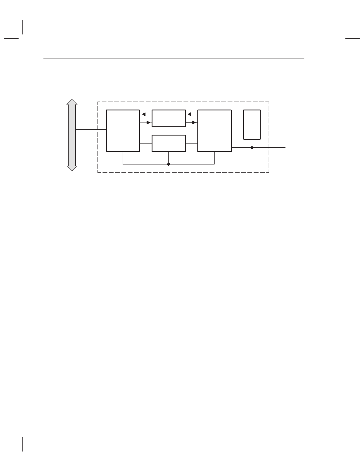
1.1 ThunderLAN Architecture
Figure 1–1.The ThunderLAN Controller
PCI Bus
PCI
controller
An integrated PHY provides interface functions for 10Base-T carrier sense
multiple access/collision detect (CSMA/CD) (Ethernet). A MII is used to communicate with the integrated PHY. The PHY is an independent module from
the rest of the ThunderLAN controller. This allows the PHY to be reset and
placed in a power-down mode.
FIFO
registers
Multiplexed
SRAM
LAN
controller
PHY
LAN
802.3
100M-bps
MII
The PCI controller is responsible for direct memory accesses (DMAs) to and
from the host memory . It is designed to relieve the host from time-consuming
data movements, thereby reducing use of the host CPU. The PCI interface
supports a 32-bit data path.
ThunderLAN supports two transmit and one receive channels. The demand
priority protocol supports two frame priorities: normal and priority. The two
transmit channels provide independent host channels for these two priority
types. CSMA/CD protocols only support a single frame priority, but the two
channels can be used to prioritize network access, if needed. All received
frames pass through the single receive channel.
ThunderLAN’s multiplexed SRAM is 3.375K bytes in size. This allows it to support one 1.5K byte FIFO for receive, two 0.75K byte FIFOs for the two transmit
(Tx) channels, and three 128-byte lists (see section 5.1, List Management). In
one-channel mode, the two Tx channels are combined, giving a single 1.5Kbyte FIFO for a single Tx channel. Supporting 1.5K byte of FIFO per channel
allows full frame buffering of Ethernet frames. PCI latency is such that a minimum of 500 bytes of storage is required to support 100M-bps LANs. (Refer to
PCI Local Bus Specification,
the
revision 2.0, section 3.5, Latency).
ThunderLAN’s industry-standard MII permits ease of upgrade. External devices can be connected to the MII and managed, if they support the two-wire
management interface. PHY layer functions for 100M-bps CSMA/CD and demand priority are connected to the MII.
1-2
Page 20

1.2 Networking Protocols
The MII also allows freedom in choosing a networking protocol. It allows the
use of standard 100M bps CSMA/CD PHY chips. ThunderLAN uses these signal lines to interface to an external 100M bps demand priority PHY . This gives
ThunderLAN the flexibility necessary to handle 10Base-T, 10Base-2,
10Base-5 AUI, 100Base-TX, 100Base-T4, 100Base-FX, and 100VG-AnyLAN
today, while supporting emerging technologies.
ThunderLAN is designed to simplify the software used to transmit frames, receive frames, and service the PHY events. It accomplishes this by integrating
time-consuming tasks into the controller. These tasks include:
-
The DMA of data into and out of the controller
-
A simplified, interrupt-driven frame buffer management technique
-
The elimination of PHY register polling through MII interrupts
DMA of data is handled through list structures. ThunderLAN’s method of handling data through list structures has parallels with the method used in Texas
Instruments TI380 COMMprocessors. There are some differences, such as
the use of a 0 forward pointer.
Networking Protocols
ThunderLAN is designed to meet
its PCI interface standards.
PCI Local Bus Specification
, revision 2.0 for
ThunderLAN Overview
1-3
Page 21

PCI Interface
1.3 PCI Interface
1.3.1 PCI Cycles
The PCI local bus is a high-performance, 32- or 64-bit bus with multiplexed address and data lines. The bus is designed to be a medium between highly integrated peripheral controller components such as ThunderLAN, add-in boards,
and processor/memory systems.
ThunderLAN executes the following cycles when it acts as the PCI bus master.
The hexadecimal number shown is the bus command encoded in the PC/
BE[3::0]# signals.
-
0x7h–memory write
-
0xCh–memory read multiple
-
0xEh–memory read line
ThunderLAN responds to the following PCI cycles when acting in slave mode
on the PCI bus:
-
0x2h–I/O read
-
0x3h–I/O write
-
0x6h–memory read
-
0x7h–memory write
-
0xAh–configuration read
-
0xBh–configuration write
-
0xCh–memory read multiple
-
0xEh–memory read line
-
0xFh–memory write and invalidate
1-4
Future versions of ThunderLAN may not be limited to these PCI cycles. T exas
Instruments reserves the right to add or delete any cycles to the ThunderLAN
PCI controller. When designing a system, ensure that the attached interface
to ThunderLAN is fully compliant with the
PCI Local Bus Specification
.
Page 22

1.3.2 Byte Ordering
PCI Interface
ThunderLAN follows the
ferring data on the PCI bus. The PCI bus data is transferred on the P AD[31::0]
lines. PAD31 is the most significant bit, and PAD0 is the least significant bit.
The 32 data lines are enough to transfer four bytes per data cycle. Byte 0 is
the LSbyte and byte 3 is the MSbyte. Byte 0 uses bits 0–7, byte 1 uses bits
8–15, byte 2 uses bits 16–23, byte 3 uses bits 24–31.
Figure 1–2. PCI Bus Byte Assignment
31
ThunderLAN uses the full four bytes per data cycle. The only exception is when
the data to be transferred is not octet aligned. In this case, the PCI controller
might not transfer the full four bytes on the first cycle. ThunderLAN deasserts
the IRDY signal only once, if needed, to synchronize the PCI bus to the internal
64-bit architecture. The deassertion of IRDY occurs on the third cycle of the
PCI bus. ThunderLAN does not deassert IRDY for the rest of the transfer unless the PCI bus asserts the TRDY signal.
PCI Local Bus Specification
convention when trans-
07815162324
Byte 0Byte 1Byte 2Byte 3
ThunderLAN Overview
1-5
Page 23

1-6
Page 24

Chapter 2
ThunderLAN Registers
ThunderLAN uses a variety of registers to perform its networking functions.
These include peripheral component interface (PCI) registers, host registers,
internal direct input/output (DIO) registers, media independent interface (MII)
registers, and physical interface (PHY) registers. Access to these is a requirement for setting up the ThunderLAN controller and any of the PHY devices attached to the MII. They must be accessed as well for transmission, initiation,
and reception of data. Other activities which require the user to understand
ThunderLAN’s register spaces include determining the cause of event-driven
interrupts and how to clear them and diagnostic functions. This chapter explains register configurations and discusses control of these spaces through
code examples.
Topic Page
2.1 Register Addresses 2-2. . . . . . . . . . . . . . . . . . . . . . . . . . . . . . . . . . . . . . . . . . .
2.2 PCI Configuration Space 2-4. . . . . . . . . . . . . . . . . . . . . . . . . . . . . . . . . . . . . .
2.3 Host Registers 2-9. . . . . . . . . . . . . . . . . . . . . . . . . . . . . . . . . . . . . . . . . . . . . . . .
2.4 Internal Registers 2-11. . . . . . . . . . . . . . . . . . . . . . . . . . . . . . . . . . . . . . . . . . . .
2.5 MII PHY Registers 2-15. . . . . . . . . . . . . . . . . . . . . . . . . . . . . . . . . . . . . . . . . . . .
2.6 External Devices 2-25. . . . . . . . . . . . . . . . . . . . . . . . . . . . . . . . . . . . . . . . . . . . .
2-1
Page 25
Register Addresses
2.1 Register Addresses
The following figure shows the various register spaces provided by ThunderLAN. It also shows how a driver uses ThunderLAN’s registers to interface to
external devices such as PHYs, BIOS ROMs, and EEPROMs.
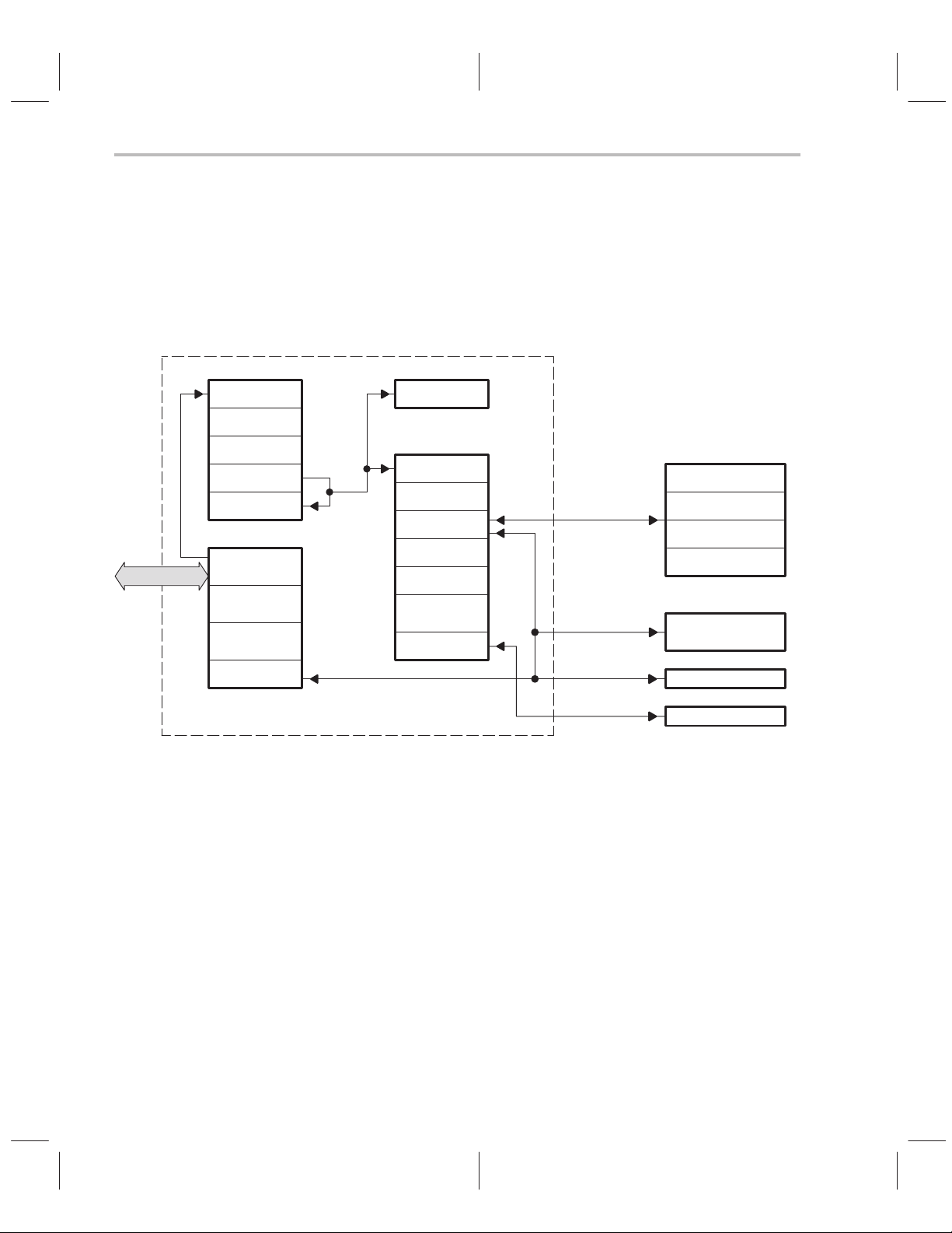
Figure 2–1. How ThunderLAN Registers are Addressed
ThunderLAN
Host registers
SRAM
Internal/DIO registers
NetCmd
NetSts
NetSio
AREG0–3
HASH
Statistics
registers
LEDreg
PCI
HOST CMD
CH PARM
HOST INT
DIO ADR
DIO DATA
PCI registers
I/O base
address
Memory
base address
BIOS ROM
base address
PCI NVRAM
MDIO/MDCLK
EDIO/EDCLK
MII/PHY registers
Generic
Autonegotiation
Reserved
PHY specific
Serial EEPROM
BIOS ROM
2-2
LED IF
LED
One block of registers, the host registers, appear at a programmable place in
memory or port address space, directly on the PCI bus. The beginning address
is determined by the value written into the PCI configuration space base address registers. Once the base register’s address is determined, ThunderLAN
reads and writes to these registers like ordinary memory or I/O ports. Since the
ThunderLAN devices are directly connected to the PCI, there is no external
decode logic that generates a chip select—all the decode is done internally.
ThunderLAN’s internal/DIO registers are accessed via the DIO_ADR and
DIO_DA TA registers in the host register group. An address is placed in the host
DIO_ADR register , and the data to be read or written to the DIO register is read
or written to the DIO_DA TA register. The internal/DIO register space is referenced indirectly via the host registers to minimize the amount of host address
space required to support the ThunderLAN controller. External devices and
their data are also reached via indirect reference through the host registers
Page 26

Register Addresses
and PCI configuration registers to make control of the system possible through
the one PCI interface.
An EEPROM, required by the PCI, can be written to at manufacture time
through the PCI_NVRAM register, which is located in the host register space.
The EEPROM can also be accessed through the NetSio register which is located in the internal/DIO register space. Control registers on the PHY side of
the MII management interface can be similarly written and read through the
NetSio register.
A BIOS ROM can be enabled via the BRE bit in the PCI BIOS ROM base address register, and its chip selected address dynamically assigned via a base
register in the configuration space. The BRE bit points to a valid address in the
ROM address space which causes two byte-address strobe cycles (EALE,
EXLE) and a read before the PCI cycle is completed.
ThunderLAN Registers
2-3
Page 27

PCI Configuration Space
2.2 PCI Configuration Space
Figure 2–2.The PCI Configuration Space Registers
Base class
(02h)
Reserved
Vendor IDDevice ID
Status Command
Subclass
Reserved
(00h)(00h)
I/O base address
Memory base address
Reserved (00h)
Cardbus CIS Pointer
Reserved (00h)
BIOS ROM base address
Reserved (00h)
Reserved (00h)
Reserved (00h)
Reserved (00h)
Reserved (00h)
Reserved (00h)
Program interface
(00h)
Latency
timer
Int pin(01h)Min_GntMax_Lat
Byte 0Byte 1Byte 2Byte 3
Revision
Cache line
size
Interrupt line
Reset control
IntDis
031
read only
00h
read/write
04h
read only
08h
read/write
0Ch
read/write
10h
read/write
14h
18h
28h
2Ch
read/write
30h
34h
38h
read/write
3Ch
read/write
40h
44h
48h
read only
2-4
Reserved (00h)
Reserved (00h)
PCI NVRAM
B4h
read only
FFh
Register configuration space information fields are needed to identify a board
in a slot to a driver. The functional purpose of the board, the manufacturer , the
revision, and several bus requirements can be obtained by inspecting these
parameters. The PCI configuration space uses these registers which are
called out in the
-
Identify the ThunderLAN controller. This includes setting the interrupt as-
PCI Local Bus Specification.
These enable the PCI system to:
signed to ThunderLAN.
-
Map the host registers using either the I/O base address register or the
memory base address register. The driver uses the address contained in
these registers to access ThunderLAN’s internal registers.
Page 28
PCI Configuration Space
-
Set up the PCI bus. Several PCI bus options can be selected through
these registers, including latency and grant. (Refer to
ification,
-
Map a BIOS ROM using the BIOS ROM base address register
subsection 3.5)
PCI Local Bus Spec-
Many of the registers in the PCI configuration space are accessed with PCI
BIOS calls. Refer to the
PCI Local Bus Specification,
chapter 6, for the commands supported by your specific PCI BIOS. Some operating systems (O/Ss)
provide BIOS call support. Your operating system’s user’s guide contains
these specific BIOS support routines.
The PCI specification requires that a bus-resident device respond to bus cycle
codes reserved for reading and writing to configuration space. See the
Local Bus Specification
document for more information on how these short,
PCI
slot-dependent address spaces appear to the host processor. The shaded
registers in Figure 2–3 can be autoloaded from an external serial EEPROM.
Check the following before accessing the PCI configuration space:
-
Ensure that there is a PCI BIOS present or other support for BIOS calls.
-
Ensure that the BIOS is the right revision.
-
Use a PCI BIOS call to find all attached devices on the PCI bus. Make sure
that you are talking to the right device on the PCI bus.
Attaching a pullup resistor to the EDIO pin allows the board designer to automatically read an EEPROM after reset to determine the contents of the first
eight bytes, shown shaded below. If the host attempts to read any of the configuration space during the time the adapter is reading the EEPROM, ThunderLAN rejects the request by signaling target-retry.
Figure 2–3. Configuration EEPROM Data Format
Vendor ID LSByte
Vendor ID MSByte
Device ID LSByte
Device ID MSByte
Revision
Subclass
Min_Gnt
Max_Lat
Checksum
Address
C0h
C1h
C2h
C3h
C4h
C5h
C6h
C7h
C8h
ThunderLAN Registers
2-5
Page 29

PCI Configuration Space
Normally , access to the configuration space is limited to the operating system.
On power-up, the vendor ID, device ID, revision, subclass, Min_Gnt, and
Max_Lat registers are loaded with default values. Vendor-specific data is
loaded into these registers by placing the data into the EEPROM, which is read
at the end of reset if autoload is enabled with a pullup resistor on the EDIO pin.
If the data read from the EEPROM has a checksum error, values are fetched
from the default PCI parameter registers, which are located at addresses
0x08h to 0x0Fh in the internal/DIO registers space.
Some fields in the configuration space like the bits in the memory base address
register and the I/O base address register, which indicate the space size allocation required to access the host registers, are hardwired in the ThunderLAN controllers. Some of the allowed PCI configuration space values like base
registers beyond the basic I/O and memory base registers are not implemented because no other entities are supported by this PCI interface other than the
network function.
To find register information, you must first identify the PCI function ID:
//––––––––––––––––––––––––––––––––––––––––––––––––––––––––
// PCIFindDevice – Find PCI device
//
// Parameters:
// DeviceID WORD The device ID
// VendorID WORD The vendor ID
// Index WORD index (normally 0, use when more than
1 device)
// pDev WORD* Where to put the device id
//
// Return val:
// int 0 if successful. see std return codes in
header
//––––––––––––––––––––––––––––––––––––––––––––––––––––––––
WORD PciFindDevice(
WORD deviceID,
WORD vendorID,
WORD Index,
WORD *pDev)
{
union REGS r;
2-6
Page 30

PCI Configuration Space
r.h.ah = PCI_FUNCTION_ID;
r.h.al = FIND_PCI_DEVICE;
r.x.cx = DeviceID;
r.x.dx = VendorID;
r.x.si = Index;
int86(PCI_INT, &r, &r);
*pDev = (WORD)r.x.bx;
return (int)r.h.ah;
}
This code returns the function ID that is used to request reads and writes to
the ThunderLAN PCI configuration space; this varies from installation to installation, based on hardware implementation and slot. This ID is necessary to determine where ThunderLAN is. The device ID indicates a networking card, and
the vendor ID is the manufacturer code. These values can be overlaid in the
configuration space with values from the EEPROM during the autoconfiguration. These should be available to the driver software either in the BIOS ROM
or on machine-readable media supplied with the network board(s).
The following example reads a byte of a PCI register:
//––––––––––––––––––––––––––––––––––––––––––––––––––––––––
// PciRdByte() – Read a byte from PCI configuration space
//
// Parameters:
// devid WORD pci device identifier
// addr WORD config address
//
// Return val:
// BYTE value read
//––––––––––––––––––––––––––––––––––––––––––––––––––––––––
BYTE PciRdByte(WORD devid, WORD addr)
{
union REGS r;
r.h.ah = PCI_FUNCTION_ID; /* PCI_FUNCTION_ID
0xB1 */
r.h.al = READ_CONFIG_BYTE; /* READ_CONFIG_WORD
0x09 */
r.x.bx = devid;
ThunderLAN Registers
2-7
Page 31

PCI Configuration Space
r.x.di = addr;
int86(PCI_INT, &r, &r); /* PCI_INT 0x1A */
return (r.x.cx & 0xFF);
}
Normally , the constants in this routine (the values assigned to ah, al, and the
opcode for the int86 call) are assigned in the header file for the C code. Their
values are inserted as comments to enable the reader to resolve the actual values that are used. The device ID, devid, is known to the driver and is used with
another PCI O/S call to find the base addresses needed for this call.
//––––––––––––––––––––––––––––––––––––––––––––––––––––––––
// PciRdWord() – PCI read config word
//
// Parameters:
// devid WORD pci device number
// addr WORD address to read
//
// Return val:
// WORD value read
//––––––––––––––––––––––––––––––––––––––––––––––––––––––––
WORD PciRdWord(WORD devid, WORD addr)
{
union REGS r;
r.h.ah = PCI_FUNCTION_ID;
r.h.al = READ_CONFIG_WORD;
r.x.bx = devid;
r.x.di = addr;
int86(PCI_INT, &r, &r);
return(r.x.cx);
}
2-8
This code passes an address >10 if the driver regards the host registers as
memory locations (ThunderLAN’s first base address register is hardwired as
a memory base register), or >14 if the driver treated the host registers as an
I/O block (ThunderLAN’s second base register is hardwired as an I/O base
register). For the I/O port, the following C instruction could be used to put a value into the DIO_ADR host register:
outpw(base_addr+OFF_DIO_ADDR,value);
OFF_DIO_ADDR is a constant for the header file. A memory transfer instruction is used if memory space is used instead of I/O space.
Page 32

2.3 Host Registers
Figure 2–4. Host Registers
ThunderLAN implements the host registers shown above. These are the primary control points for ThunderLAN. Through the host registers, a driver can:
-
Reset the ThunderLAN controller
-
Start transmit and receive channels
-
Handle interrupts: Acknowledge interrupts, turn certain kinds of interrupts
on or off, or pace interrupts with the host
-
Access the internal registers
-
Access the internal SRAM for diagnostic purposes
HOST_CMD
CH_PARM
DIO_DATA
Host Registers
Base address
offset
0151631
+0
+4
DIO_ADRHOST_INT
+8
+12
HOST_CMD register gives commands to the ThunderLAN controller. It is
The
used in conjunction with the CH_PARM register to start the transmit and receive processes (Tx GO/Rx GO). It is also used in conjunction with the
HOST_INT register to acknowledge (ack) interrupts. Through HOST_CMD,
interrupt pacing can be selected.
The CH_PARM register is used to give the physical addresses of a transmit
or receive list to ThunderLAN’s direct memory access (DMA) controller . ThunderLAN uses the address in the CH_PARM register to DMA data into or out
of its FIFOs. In an adapter check, an error condition where ThunderLAN must
be reset, CH_PARM contains information on the nature of the error.
HOST_INT register contains information on the type of interrupt that was
The
given to the host processor. It is also used with the CH_P ARM register to indicate adapter checks. HOST_INT is designed to make interrupt handling routines simple and powerful. The last two significant bits are set to 0 so that this
register may be used as a table offset in a jump table. The bit definitions are
mapped to the most significant word (MSW) of the HOST_CMD
register. This
allows acknowledging of interrupt operations by simply taking the value in
HOST_INT and writing it to HOST_CMD.
The DIO_ADR and DIO_DA TA registers work in tandem to allow accesses to
the internal DIO registers and SRAM. The value in DIO_ADR selects the register or memory locations to be accessed.
ThunderLAN Registers
2-9
Page 33

Host Registers
To enable reads of adjacent addresses without reposting the address, bit 15
of the DIO_ADR register can be set, which causes the address to be post-incremented by 4 after each access of the DIO_DA TA register. This function is
useful when reading the statistics or reading the internal SRAM. Autoincrementing while reading the FIFO memory causes a move to the same part of
the next 68-bit word; it does not move to the next part of the same 68-bit word.
The two least significant bits (LSBs) of the DIO_ADR must be expressly set
to get to the various parts of each 68-bit entity.
The host registers are addressed either as memory or I/O ports. The PCI configuration space has locations for the O/S to assign up to six memory or I/O
base addresses. The depth of the space requested for each base register implemented is determined by the number of bits, starting at the LSBs, whose
values are fixed. The O/S writes to the rest of the bits (with the assumption that
the fixed positions are equal to 0) at the beginning address of that block.
As an example, the LSB determines whether the base register is a memory
(0) or an I/O space (1) base register. ThunderLAN’s PCI interface reserves
memory I/O space by implementing an I/O and a memory configuration base
register, both with the four LSBs in these registers fixed to indicate the field
width requested be reserved in the respective address space for the host register block (four quad words or 16 bytes). The rest of the bits of a base register
are filled in by the O/S after all the space requests are considered.
2-10
Assigning space in this way assures that all starts of fields are naturally aligned
to long words or better. It is important to note that by the time either the BIOS
code or driver code is allowed to run, the O/S has queried the card and assigned the base addresses. The host registers can be accessed equally in
both address spaces on host processor systems that support both.
Some processors only support memory spaces; in these cases the I/O spaces
are assigned a 0, which is not a valid base register value for a peripheral. The
driver must check for a 0 base offset value before using the I/O method of
accessing the ThunderLAN registers. The base offset must be constant between host processor resets, but can be different for each execution of the program. All host register accesses are done relative to the value found in the respective configuration base register.
The unimplemented base registers in the configuration space return all 0s on
32
a read. This is equivalent to requesting a 2
-byte data space—all of the avail-
able address space in a 32-bit address system. PCI interprets an all-bits-fixed
situation as not implemented.
Page 34

2.4 Internal Registers
Figure 2–5. Internal Registers
Internal Registers
Byte 3
NetMask
Default
device ID
MSbyte
Default
Max_Lat
Areg_0
(23 to 16)
Areg_1
(39 to 32)
Areg_1
(7 to 0)
Areg_2
(23 to 16)
Areg_3
(39 to 32)
Areg_3
(7 to 0)
Tx underrun
Rx overrun
Code error
frames
Acommit
Byte 2
NetSts
Default
device ID
LSbyte
Default
Min_Lat
Areg_0
(31 to 24)
Areg_1
(47 to 40)
Areg_1
(15 to 8)
Areg_2
(31 to 24)
Areg_3
(47 to 40)
Areg_3
(15 to 8)
CRC error
frames
Carrier loss
errors
Byte 1
NetSio
Default
vendor ID
MSbyte
Default
Subclass
Areg_0
(39 to 32)
Areg_0
(7 to 0)
Areg_1
(23 to 16)
Areg_2
(39 to 32)
Areg_2
(7 to 0)
Areg_3
(23 to 16)
HASH1
HASH2
Good Tx frames
Good Rx frames
Multicollision Tx framesSingle collision Tx frames
Late
collisions
NetConfigMan Test
vendor ID
revision
(47 to 40)
(31 to 24)
(47 to 40)
(31 to 24)
Deferred Tx
frames
Excessive
collisions
Byte 0
NetCmd
Default
LSbyte
Default
Areg_0
Areg_0
(15 to 8)
Areg_1
Areg_2
Areg_2
(15 to 8)
Areg_3
LEDregBSIZEregMaxRx
DIO address
0x00
0x04
0x08
0x0C
0x10
0x14
0x18
0x1C
0x20
0x24
0x28
0x2C
0x30
0x34
0x38
0x3C
0x40
0x44
The internal registers are used less often than the host registers. They are
used for:
-
Setting diagnostic options, such as loopback (wrap) and copy all frames
-
Setting network options. This is usually a one-time operation at initialization.
ThunderLAN Registers
2-11
Page 35

Internal Registers
-
Setting commit levels and PCI burst levels
-
Interfacing via the management interface to the PHY registers
-
Determining status interrupts
-
Setting eight bytes of default PCI configuration data if the EEPROM
checksum is bad
-
Setting the various unicast and multicast addresses
-
Providing network statistics
-
Setting the LEDs and implementing a BIOS ROM
The NetCmd
register is used to set many of the diagnostic modes such as
wrap, copy short frames (CSF), copy all frames (CAF), no broadcast
(NOBRX), duplex, and token ring frame formats. It also includes a reset bit,
which is used to allow changes in the NetConfig register for additional network
configuration options.
,
NetSio, the network serial I/O register
is used to control the MDIO/MDCLK
management interface. It is also used to communicate with an EEPROM, using the EDIO/EDCLK serial interface. This register can also enable or disable
PHY interrupts.
2-12
NetSts and NetMask registers work in tandem to determine the nature of
The
a status interrupt. The bits in the NetMask register are used to mask whether
the status flags in NetSts cause interrupts or not.
NetConfig register sets network configuration options during reset. This
The
register can only be written to when ThunderLAN is in reset (NRESET = 0). It
allows the controller to receive CRCs (RxCRC), pass errored frames (PEF),
use a one-fragment list on receive (refer to subsection 5.3, One-Fragment
Mode, for more information), use a single transmit channel, enable the internal
PHY, and select the network protocol (CSMA/CD or demand priority).
The AREG registers allow ThunderLAN to recognize any four 48-bit IEEE 802
address. This includes specific, group, local, or universal addresses. They can
be Ethernet or token ring addresses. The HASH registers allow group addressed frames to be accepted on the basis of a hashing table.
The statistics registers hold the appropriate network counters, including good
Tx and Rx frames, collisions, deferred frames, and error counters. The LEDs
are controlled through the
LEDreg register, which directly controls the values
output on the LED lines EAD[7::0]. All are, therefore, software programmable.
LEDreg can also be used to implement a BIOS ROM. The
Acommit register
Page 36

Internal Registers
is used to set the network transmit commit level. The BSIZEreg register is used
to set the bus burst size on both Tx and Rx frames.
The internal registers are accessed via the DIO_DATA and DIO_ADR host
registers. DIO_ADR holds the DIO address of the register. The data is then
read from or written to DIO_DATA.
Before one can write to an internal register, one must find the proper address
for the host registers to use as pointers to the internal register block, and decide whether to use the memory pointer or the I/O port pointer value. Following
is an example of x86 C code to access a byte from an internal register using
the I/O port pointer value:
//––––––––––––––––––––––––––––––––––––––––––––––––––––––––
// DioRdByte() – Read byte from adapter internal register
//
// Parameters:
// base_addr WORD base address of TLAN internal registers
// addr WORD offset of register to read
//
// Return val:
// BYTE value read
//––––––––––––––––––––––––––––––––––––––––––––––––––––––––
BYTE DioRdByte(WORD base_addr, WORD addr)
{
outpw(base_addr+OFF_DIO_ADDR, addr);
return(inp((base_addr+OFF_DIO_DATA) + (addr&3)));
}
The address of the register being read is determined by the calling program
and is passed to this routine as a parameter, along with the the I/O base address. An output is executed to the DIO_ADR host register as part of setting
up the pointer address. In x86 architectures, there are separate instructions
for 16-bit port writes and 8-bit port writes; the 16-bit version is used to write all
the address field’s 16 bits in one operation. Internally , this causes the data from
the internal register at that address to be deposited in the DIO_DA T A host register. A byte read of the data register gets the LSbyte (addr&3). A more sophisticated routine honors the address of the byte specifically requested and sees
that those eight bits are shifted down to a byte to be returned. If you want to
read a whole word from one of the internal registers (32 bits), you could perform two 16-bit reads and merge the values to be returned as a 32-bit value
like this:
ThunderLAN Registers
2-13
Page 37

Internal Registers
//––––––––––––––––––––––––––––––––––––––––––––––––––––––––
// DioRdDword() – read 32 bits from internal TLAN register
//
// Parameters:
// base_addr WORD base address of TLAN internal registers
// addr WORD address to read
//
// Return val:
// DWORD value read
//––––––––––––––––––––––––––––––––––––––––––––––––––––––––
DWORD DioRdDword(WORD base_addr, WORD addr)
{
DWORD data;
addr &= 0x3fff;
outpw(base_addr+OFF_DIO_ADDR, addr);
data = ((DWORD)inpw(base_addr+OFF_DIO_DATA))&0x0000ffffl;
data |= ((DWORD)inpw(base_addr+OFF_DIO_DATA+2)) << 16l;
return(data);
}
2-14
Page 38

2.5 MII PHY Registers
Figure 2–6. MII PHY Registers
Register
MII PHY Registers
Description
Control
Status
PHY identifier
PHY identifier
AN advertisement
AN link-partner ability
AN expansion
AN next page transmit
Reserved
Reserved
Reserved
Vendor-specific registers
Vendor-specific registers
Vendor-specific registers
0x00
0x01
0x02
0x03
0x04
0x05
0x06
0x07
0x08
through
0x0F
0x10
through
0x1F
PHY generic control register
PHY generic status register
PHY generic identifier (high)
PHY generic identifier (low)
Autonegotiation advertisement
Autonegotiation link-partner ability
Autonegotiation expansion
Autonegotiation next page transmit
Reserved by IEEE 802.3
Vendor-specific registers
The 802.3 standard specifies a basic set of registers that must be present.
These include a control register at 0x00 and a status register at 0x01. An extended set from 0x02 through 0x1F can also be implemented. Within the extended set, 0x02 through 0x07 are defined and 0x08 through 0x0F are reserved. The area between 0x10 and 0x1F can be used for vendor-specific applications. The basic set of registers is shown in dark gray above. The extended registers are shown in lighter gray and white. The light gray registers
are those defined by 802.3, and the white registers are vendor-specific. The
register specification for the internal 10Base-T PHY in ThunderLAN controllers is shown in Appendix A. We have also included the register specification
for the TNETE21 1 100VG-AnyLAN physical media interface (PMI) in Appendix B.
The PHY registers are accessed to:
-
Initialize the PHY, bring it in and out of reset, and isolate it from the MII
-
Set PHY options, such as duplex and loopback
-
Determine the type of speed and protocol supported by the PHY
-
Conduct autonegotiation, if supported
-
Select any vendor-specific options
The control register (GEN_ctl in ThunderLAN products) controls PHY options
such as reset, loopback, duplex, and autonegotiation enable. It also powers
down and isolates the PHY from the MII.
ThunderLAN Registers
2-15
Page 39

MII PHY Registers
The status register (GEN_sts in ThunderLAN products) includes bits to identify
the technology supported by the PHY. This technology includes protocol and
duplex abilities. It indicates link, jabber, and autoconfiguration completion. Bit
0 of the status register also indicates whether the extended register set is supported.
The PHY identifier registers (GEN_id_hi/GEN_id_lo in ThunderLAN products)
contain an identifier code for the silicon revision and the silicon manufacturer.
Registers 0x04 thru 0x07 are used in the autonegotiation process. They include the autonegotiation advertisement, autonegotiation link partner ability,
autonegotiation expansion, and autonegotiation next page registers (AN_adv ,
AN_lpa, AN_exp respectively).
In the vendor-specific area, T exas Instruments has implemented a TLPHY_id
register. This register is used to identify ThunderLAN-specific PHY devices.
ThunderLAN also implements a specific control register, TLPHY_ctl, and status register, TLPHY_sts. The particulars of these registers change from PHY
to PHY. Please refer to Appendix A for the PHY that you are using.
Writing to a register in a PHY through the management interface involves writ-
,
ing data and clock bits into NetSio
an internal register, which uses the pointer
host registers. The data unit to or from a PHY register is always 16 bits.
The NetSio register uses three bits to drive the MDIO/MDCLK MII manage-
ment interface. These bits are MCLK, MTXEN, and MDA TA. These bits directly
control the voltages present in the management interface and function like
this:
-
MCLK directly controls the MDCLK signal. Setting MCLK in NetSio high
causes a logic 1 to appear on the MDCLK pin. Setting MCLK in the NetSio
register low causes a logic 0 to appear on the MDCLK pin.
-
MTXEN controls the direction of the MDIO pin.
J
When MTXEN is high, MDIO is driven with the value written on
MDATA.
J
When MTXEN is low, MDATA mirrors the MDIO line.
Multiple PHYs can be attached to one MII. PHYs are selected through an address which can be in a range from 0x00 to 0x1F. Some vendors’ PHYs have
pins that can be pulled up or down to indicate the PHY address. In order for
a particular PHY to be addressed, the driver must know the PHY address beforehand.
ThunderLAN’s internal PHY for 10Base-T can only support two addresses.
When used in conjunction with the rest of the ThunderLAN device, the address
2-16
Page 40

MII PHY Registers
is 0x1F. When the internal PHY for 10Base-T is used in a standalone mode,
that is, when run from another controller through the MII pins, it is at address
0x00. These are the only two addresses allowed for the internal PHY.
The 100VG-AnyLAN PMI device, the TNETE211, is used to attach 802.12
physical media dependent (PMD) devices to ThunderLAN’s MII. The
TNETE21 1 has five external pins (DEVSEL[4::0]) that program the address to
which it will respond. If multiple PHYs are used, each must be installed with
a unique address.
Before reading or writing to any PHY register, the MII serial interface must be
synchronized. This involves a one-time write of 32, 1 bits on the MDIO pin.
Once this is done, an access can be done with a two-bit start delimiter, then
a two-bit op code (for read or write), followed by five bits of PHY address, five
bits of register address, two bits of turnaround time in case the PHY is going
to write to the data line, and 16 bits of data.
The synchronization code could be done this way:
//––––––––––––––––––––––––––––––––––––––––––––––––––––––––
// MIISync() – send MII synchronization pattern to all
// possible MII interfaces
//
// Parameters:
// base_addr base address on TLAN internal registers
//
// Return val:
// none
//––––––––––––––––––––––––––––––––––––––––––––––––––––––––
void MIISync(WORD base_addr)
{
register int i;
clr(MTXEN);
where clr is a macro to set a bit to 0 in the NetSio internal register. In this case,
bit MTXEN in NetSio is cleared.
#define clr(x)
DioWrByte(base_addr,Net_Sio,(BYTE)(DioRd
Byte(base_addr,Net_Sio)&~x))
When the output enable bit is cleared and the PHYs have just been turned on,
none of them outputs data. The value on the data line is determined by the pull-
ThunderLAN Registers
2-17
Page 41

MII PHY Registers
up resistor, which is recommended to be attached to this line. The MII devices
should see 1s.
An alternate way to give the PHYs a series of 1s, is to:
set(MDATA)
set(MTXEN)
clr(MCLK);
//delay here
DioRdByte(base_addr,Net_Sio);
set(MCLK);
Where MCLK is a constant for the third LSB (in the internal NetSio register)
and is defined as:
//delay
DioRdByte(base_addr,Net_Sio);
set(NMRST);
This is the command to set a bit to 0 in the internal NetSio register. In this case,
the MCLK bit in NetSio is set. Set could be defined this way:
#define set(x)
DioWrByte(base_addr,Net_Sio,(BYTE)(DioRdByte
(base_addr,Net_Sio) |x))
The routine to synchronize the PHYs is part of the startup code. The controller
at this point is held in reset due to the drivers writing a 1 to the Ad_Rst bit, bit
15 in the HOST_CMD register, or a reset being received on power-up through
the PCI system. Setting the NMRST bit to 0 places the MII bus in a reset state.
for (i = 0;i < 32;i++)
togLH(MCLK);
The command togLH is a combination of the clr and set commands on the
passed parameter and is defined this way:
#define togLH(x) {clr(x); \
set(x);}
}
togLH is repeated 32 times to give PHYs the 32, 1 data bits that they need to
get synchronized. Note that the clock line is left in the high state at the end of
the loop.
2-18
Page 42

MII PHY Registers
After synchronization, one could use code like the following to read a PHY register:
//––––––––––––––––––––––––––––––––––––––––––––––––––––––––
// MiiRdWord() – Read word from Phy MII, place at ptr,
return status
//
// Parameters:
// base_addr WORD base address of TLAN internal regis-
ters (passed
// for set/clr macros)
// dev WORD device to read from
// addr WORD register on dev to read from
// pval WORD* storage for data read
//
// Return val:
// int OK (0) on success, NO_ACK (1) on failure
//––––––––––––––––––––––––––––––––––––––––––––––––––––––––
int MiiRdWord(WORD base_addr, WORD dev, WORD addr, WORD
*pval)
{
// mread array: 01 is the start delimiter sequence for
the MII
// interface, 10 specifies the operation will be a
read.
// See IEEE 802.3u
WORD i,tmp;
char ack;
BYTE b;
WORD diodata = base_addr+OFF_DIO_DATA+Net_Sio;
CritOn();
outpw(base_addr+OFF_DIO_ADDR,Net_Sio);
This example uses the host registers as I/O ports, so the code needs to resolve
a pointer to the host NetSio register. NetSio is added to the base DIO_DATA
register address to give the byte offset. The NetSio register is only one byte
long, and a byte port read instruction needs to activate the proper byte strobe
in the PCI interface. Filling in the lowest two bits with the NetSio offset constant
causes the NetCmd register to be read.
ThunderLAN Registers
2-19
Page 43

MII PHY Registers
Interrupts are turned off with the CritOn() macro. This macro leaves a value
that can be sampled to see if it has been invoked. CritOn can be defined as
follows:
#define CritOn() if (CritLevel == 0) \
{ _asm { cli } } \
CritLevel++
The NetSio register must be reached indirectly using the host registers. This
sets the address of the NetSio register, of fset from the beginning of the internal
register block, in the host register which is used as an address pointer to the
Internal registers. This is a two-active-byte-strobe (out of four) write cycle. The
DIO_ADR register is 16 bits in width.
b = inp(diodata);
b &= ~MINTEN;
b &= ~MDATA;
b |= MCLK;
outp(diodata,b);
This cycle reads, modifies, and writes the contents of the NetSio register. It
turns off the MII interrupt by forcing the MINTEN bit to a logic low , makes sure
the data bit in the interface comes on with a logic low when enabled in the next
write, and makes sure the clock line in the two-wire MII management interface
starts high.
b |= MTXEN;
outp(diodata,b);
The previous code turns on the data output driver. ThunderLAN has to write
several fields to the MII before data is passed in either direction.
//togLH
b &= ~MCLK; outp(diodata,b);
b |= MCLK; outp(diodata,b); //0 data bit out
2-20
Page 44

MII PHY Registers
This samples data on the rising edge of the MCLK bit. T ake the first bit into the
PHY MII as follows:
b &= ~MCLK; outp(diodata,b);
b |= MDATA; outp(diodata,b);
b |= MCLK; outp(diodata,b); //1 data bit out
This concludes writing out the start delimiter bits. The data can be changed
before the clock is taken low, as when shifting out the operation code as follows:
b |= MDATA; outp(diodata,b); //1st part not nec.
//togLH
b &= ~MCLK; outp(diodata,b);
b |= MCLK; outp(diodata,b); //1
b &= ~MDATA; outp(diodata,b);
//togLH
b &= ~MCLK; outp(diodata,b);
b |= MCLK; outp(diodata,b); //0
10 is the read op code for an MII management operation.
// Send the device number Internal=31(0x1f),
External=0(0x00)
for (i = 0x10;i;i >>= 1) /* 10 is the read op code*/
{
if (i&dev)
b |= MDATA;
else
b &= ~MDATA;
outp(diodata,b);
//togLH
b &= ~MCLK; outp(diodata,b);
b |= MCLK; outp(diodata,b);
}
The following loop index is used as a mask to walk through the device number
which is passed to this routine as a parameter. Each loop looks at a bit in the
device number, starting with the MSB. It sets the MDA T A bit to match the internal representation of the NetSio register before outputting the composite value
ThunderLAN Registers
2-21
Page 45

MII PHY Registers
to NetSio. Then the clock is cycled for each bit. The loop effectively cycles five
times.
// Send the register number MSB first
// Send the device number Internal=31(0x1f),
External=0(0x00)
for (i = 0x10;i;i >>= 1)
{
if (i&addr)
b |= MDATA;
else
b &= ~MDATA;
outp(diodata,b);
//togLH
b &= ~MCLK; outp(diodata,b);
b |= MCLK; outp(diodata,b);
}
// 802.3u specifies an idle bit time after the register
// address is sent. This and the following zero bit are
// designated as ”Turn–around” cycles.
b &= ~MTXEN; outp(diodata,b);
2-22
To get an idle bit, turn off the data driver, then cycle the clock.
//togLH
b &= ~MCLK; outp(diodata,b); //end turn around cycle
b |= MCLK; outp(diodata,b); //this should clock “0”
ackn bit out
b &= ~MCLK; outp(diodata,b); //take clock low wait
for data valid
Page 46

MII PHY Registers
After the addresses have been clocked out on a read cycle, there is a cycle
where neither side drives the data pin. If the PHY is synced and ready to respond, it should drive a 0 next, followed by the 16 bits of data. The data is available up to 300 ns after the rising edge of the clock, so the software loop uses
that time to execute the instruction to make the clock go low again.
// Get PHY Ack
ack = inp(diodata);
if (!(ack & MDATA)) // if ack=0, record bits
{
b |= MCLK; outp(diodata,b); // complete ack
cycle clock
for (tmp = 0,i = 0x8000;i;i >>= 1)
The loop is set for 16 cycles, using the loop variable as a mask for pointing to
the bit position stored. The MSB comes in first. For each shift cycle, the clock
goes up to start the access and goes down to guarantee that some time
elapses between the rising edge of the clock and the time the data is sampled.
{
b &= ~MCLK; outp(diodata,b);
if (inp(diodata)&MDATA)
tmp |= i; //if data bit=1, or position in
b |= MCLK; outp(diodata,b);
}
}
else
If the PHY does not respond, one needs to complete the access cycle to keep
other PHYs from being left in mid-access. Leave the MDIO pin set for input but
set the data variable to all 1s. This routine gives 17 clock cycles, using the macro for togHL on the MCLK bit of the NetSio register. There are 17 clock cycles,
because the first one finishes the acknowledge cycle (the clock was left in a
logic low state when the data was read).
ThunderLAN Registers
2-23
Page 47

MII PHY Registers
{
for (i = 0;i < 17;i++)
togLH(MCLK);
tmp = 0xffff;
}
//togLH
b &= ~MCLK; outp(diodata,b);
b |= MCLK; outp(diodata,b);
b = inp(diodata);
This is the quiescent cycle following data transmission. Since this is a read operation, ThunderLAN does not drive the line and the PHY turns off during this
cycle. If the quiescent cycle is not performed between the read and write operations, the PHY is not able to assert the MDIO pin low to indicate a PHY interrupt. After this cycle and a read, the driver sets the MINTEN bit high, which enables PHY interrupts.
set(MINTEN);
*pval = tmp;
CritOff();
2-24
The function value returned is reserved for completion and error codes, and
is returned via a pointer. CritOf f turns on the interrupts again and is defined as:
#define CritOff() if (––CritLevel == 0) \
{ _asm { sti } }
A similar routine with similar code is used to write values into the PHY registers
through the management interface.
Page 48

2.6 External Devices
This following section discusses the manner in which the ThunderLAN controller interfaces to external devices. These devices include:
-
-
-
-
2.6.1 BIOS ROM
A BIOS ROM is supported with two external latches and a memory device. A
memory-space base register is implemented at location 0x30h in the PCI configuration space, with 16 bits forced to fixed values. This reserves 64K bytes
of memory space. A PCI memory read is requested, and if the upper 16 bits
match the value posted in the BIOS ROM base address, hardware state machines begin a special cycle that posts the two eight-bit parts of the address
along with address strobes on the EAD[7::0] pins. The EAD[7::0] lines act as
an output bus during the output of the low eight bits signaled by the EALE
strobe, and the output of the next eight bits signaled by the EXLE strobe. They
act as an input bus when accepting the data from the EPROM which is signaled by the EOE EPROM output enable strobe. This interface is designed to
support all types of read cycles from the host: byte, word, and long word. Four
cycles are automatically done to prepare a 32-bit response to the PCI read
cycle. During the state machine’s execution, the PCI read cycle sends wait
states to the host processor. Writes to the EPROM memory space are accepted and performed, but are internally ignored.
External Devices
A BIOS ROM
Light emitting diodes (LEDs)
A serial EEPROM
Any devices (PMIs/PMDs) attached to the MDIO/MDCLK serial interface
of the MII
2.6.2 LEDs
The EAD[7::0] bus is an output bus when not involved in EPROM read cycles.
These pins are driven with the inverse of the pattern written into LEDreg, an
internal register. To access this register, a 0x44 is written to the DIO_ADR host
register, then either a byte write to the DIO_DATA host register or a read/
modify/write to the whole DIO_DA T A host register is done to deposit the value
into LEDreg. A logic 1 in the register translates to an active low on the external
output pin. All bits in this register are set to 0 on the Ad_Rst bit, or when the
external reset, PRST#, is activated.
The meaning assigned to the LEDs, which LEDs are actually implemented,
and the times to set and clear them are all programmable. Texas Instruments
ThunderLAN Registers
2-25
Page 49

External Devices
2.6.3 EEPROM
reserves the following two LED locations for its drivers. The bit numbers refer
to their locations in LEDreg.
-
Bit 0 (LSB) displays link status.
-
Bit 4 displays activity.
The implementation-specific configuration information is read or written into
the EEPROM from two sources. Control of the two-wire serial bus to the
EEPROM (EDIO and EDCLK bits) on reset (hardware or software) rests with
the four bits in the PCI_ NVRAM register (DA T A, DDIR, CLOCK, CDIR) in the
PCI configuration space. Any time this register is written to, control of the
EDIO/EDCLK bus reverts back to this register.
The other possible source of values for this bus is from an internal register, the
network serial I/O register NetSio. Here the three bits used to control the interface are EDA T A, ETXEN, and ECLOK. The PCI_ NVRAM register interface to
this external EEPROM port was designed assuming that there might be another master device on this bus. Note that NetSio does not implement a clock
direction register. Assuming that only one EEPROM is on the serial bus and
only the ThunderLAN device is driving the bus, both control implementations
are equivalent. Use NetSio when possible to read or write to the EEPROM.
2-26
Page 50

External Devices
Writing to the NetSio register involves writing a >000 to the host register
DIO_ADR, then writing to the DIO_DATA host register. Control of the
EEPROM interface shifts to the bits in NetSio when a write takes place to the
DIO_DA TA host register . Following is an example of how one might read a byte
of data from the EEPROM, using the control bits in NetSio from the internal
register block.
//––––––––––––––––––––––––––––––––––––––––––––––––––––––––
// EeRdByte() – read byte of data from EEPROM (see
Exel XL24C02 device specification)
//
// Parameters:
// base_addr WORD base address of TLAN internal
registers
// addr WORD address to read
//
// Return val:
// BYTE value read
//––––––––––––––––––––––––––––––––––––––––––––––––––––––––
BYTE EeRdByte(WORD base_addr, WORD addr)
{
int i,ips,tmp;
CritOn();
CritOn turns off the interrupts. Remember that there are two possible control
points for reading and writing to the EEPROM. This is an attempt to avoid a
control shift and avoid loss of focus on just which byte, word, or double word
one accesses, since accessing the EEPROM is a relatively long process.
// send EEPROM start sequence
set(ECLOK); set(EDATA); set(ETXEN); clr(EDATA);
clr(ECLOK);
ThunderLAN Registers
2-27
Page 51

External Devices
Set and clear are macros for a read/modify/write routine for individual bits in
the NetSio register . The NetSio byte is read indirectly from the internal register
block with the host register address and data pointers, the bit passed as a
constant (really a bit mask) is ANDed to 0 (clear), or ORed to a 1 (set). The
pattern of bits to be set and cleared is given in the data sheet for the EEPROM.
// put EEPROM device identifier, address, and write
// command on bus
sel(base_addr, WRITE);
The EEPROM, with its serial interface, must receive a wakeup pattern and a
device number, since more than one device can be tied to this bus. This code
assumes that there is only one device, 0.
// EEPROM should have acked
if (!ack(base_addr))
return (0);
// send address on EEPROM to read from
sendaddr(base_addr, addr);
sendaddr is a routine for serially sending out the address to be read from the
EEPROM. Each bit of the address must be accompanied by a clock.
// EEPROM should have ack’d address received
if (!ack(base_addr))
return (0);
// send EEPROM start access sequence
set(ETXEN); set(ECLOK); set(EDATA); set(ETXEN);
clr(EDATA); clr(ECLOK);
2-28
Page 52

External Devices
When the EEPROM address is shipped out, another special pattern of control
signal movements must take place to signal the start of the data transfer.
// send device ID, address and read command to EEPROM
sel(base_addr, READ);
// EEPROM should have acked
if (!ack(base_addr))
return (0);
//clock bits in from EDATA and construct data in tmp
for (i = 8,tmp = 0,ips = 0x80;i;i––,ips >>= 1)
{
set(ECLOK);
if (test(EDATA))
tmp |= ips;
clr(ECLOK);
}
togHL(ECLOK);
Test is a macro, like set and clear , that indirectly reads the bit passed into the
NetSio register in the internal register block using the DIO_ADR and
DIO_DATA registers in the host register block.
// send EEPROM stop access sequence
clr(EDATA); set(ECLOK); set(EDATA); clr(ETXEN);
The following control signal movements are specified in the data sheet for the
EEPROM.
CritOff();
return((BYTE)(tmp & 0xff));
}
Similar routines can be created for writing a byte, reading and writing a word,
or reading and writing a double word to the EEPROM using the NetSio regis-
ter’s control bits. In the DOS/Windows environment, there are O/S calls provided for reading and writing to PCI configuration space. Routines similar to
network serial I/O routines can be written using the PCI O/S calls, but they are
more awkward. Instead of an indirect read, modify, and write cycle, one performs an O/S PCI read call, a modify, and an O/S PCI write call for each bit
modified.
ThunderLAN Registers
2-29
Page 53

External Devices
2.6.4 ThunderLAN EEPROM Map
ThunderLAN uses the following EEPROM map. Note that these values may
be used in several applications and systems including:
-
ThunderLAN hardware
-
A host running Texas Instruments ThunderLAN drivers
-
Texas Instruments diagnostic routines
Table 2–1. ThunderLAN EEPROM Map
Address Default Binary Bits Description
0x70 0x70 ccccxbdx Acommit register and bit level PHY controls
cccc–commit level 0–7
b–Local loopback select
d–ThinNet select
0x71 0x33 ttttrrrr Transmit and receive burst size control
tttt–Transmit burst size control 0–7
rrrr–Receive burst size control 0–7
0x72 0x00 ccccbbbb PHY
0x73 0x0f Interrupt pacing timer value
0x74 0xff Configuration space Latency_Timer
0x75 0xea LSB of maximum frame size to test
0x76 0x05 MSB of maximum frame size to test
0x77 0x40 LSB of small frame in mixed frame size test
0x78
0x00 MSB of small frame in mixed frame size test
TLPHY_ctl register initialization options
cccc–Bits 15–12 of the MII register 0x11 TLPHY_ctl
bbbb–Bits 3–0 of the MII register 0x11 TLPHY_ctl
register value
2-30
Page 54

Table 2–1. ThunderLAN EEPROM Map (Continued)
Address DescriptionBinary BitsDefault
0x79 0x04 WxSHRAFI PHY and test control modes
W–PHY wrap request
S–Skip training request
H–HiPriority transmit frames request
R–Don’t copy short frame request
A–Don’t copy all frames request
F–Full duplex request
I–Internal ThunderLAN wrap request
0x7a 0x02 LFxTxADP Check modes and frame type
L–Ignore last byte plus one DMA no write test
F–Zero (ignore) bits 12 and 13 of Rx length request
T–Token ring format request
A–AT&T2X01 fix enable (receive logic state machine tweak)
D–Stop on first error
P–PMI wrap length check disable request
External Devices
0x7b 0x05 Test to execute
1–Multicast test
2–Pipe test
3–Mix pipe test
4–PMI/TI-PHY interrupt test
5–Frame read/write test
6–Adapter check test
0x7c 0x14 Pipe depth value
0x7d 0x0a Reserved
0x7e 0x00 LSB of NetConfig register value
0x7f 0x06 MSB of NetConfig register value
Note: Multichannel mode must be selected for high priority frames to be
sent
0x80 0x82
0x81
0x08
ThunderLAN Registers
2-31
Page 55

External Devices
Table 2–1. ThunderLAN EEPROM Map (Continued)
Address DescriptionBinary BitsDefault
0x82 0x00
0x83 Ethernet address
0x84 Ethernet address
0x85 Ethernet address
0x87 Ethernet address
0x88 Ethernet address
0x86 Ethernet address
0x89 0xff Checksum
0x8a 0xff Checksum
0x8b 0x83
0x8c 0x08
0x8d 0x00
0x8e Token ring address
0x8f Token ring address
0x90 Token ring address
0x91 Token ring address
0x92 Token ring address
0x93 Token ring address
0x94 0xff Checksum
0x95 0xff Checksum
0x96 0x82
0x97 0x08
0x98 0x00
0x99 Ethernet address
0x9a Ethernet address
0x9b
Ethernet address
2-32
Page 56

Table 2–1. ThunderLAN EEPROM Map (Continued)
Address DescriptionBinary BitsDefault
0x9c Ethernet address
0x9d Ethernet address
0x9e Ethernet address
0x9f 0xff Checksum
0xa0 0xff Checksum
0xa1 0x83
0xa2 0x08
0xa3 0x00
0xa4 Token ring address
0xa5 Token ring address
0xa6 Token ring address
External Devices
0xa7 Token ring address
0xa8 Token ring address
0xa9 Token ring address
0xaa 0xff Checksum
0xab 0xff Checksum
0xac 0x82
0xad 0x08
0xae 0x00
0xaf Ethernet address
0xb0 Ethernet address
0xb1 Ethernet address
0xb2 Ethernet address
0xb3 Ethernet address
0xb4 Ethernet address
0xb5
0xff Checksum
ThunderLAN Registers
2-33
Page 57

External Devices
Table 2–1. ThunderLAN EEPROM Map (Continued)
Address DescriptionBinary BitsDefault
0xb6 0xff Checksum
0xb7
0xb8
0xb9
0xba
0xbb
0xbc
0xbd
0xbe
0xbf
0xc0 Vendor ID register LSbyte
0xc1 Vendor ID MSbyte
0xc2 Device ID LSbyte
0xc3 Device ID MSbyte
0xc4 Revision
0xc5 Subclass
0xc6 Min_Gnt
0xc7 Max_Lat
0xc8
Checksum
2-34
Page 58

Chapter 3
Initializing and Resetting
This chapter describes the steps necessary to get a ThunderLAN device ready
to transmit and receive frames. It provides examples of the necessary code,
beginning with configuration of the ThunderLAN device on a peripheral component interconnect (PCI) system. The chapter also defines the steps needed
for both hardware and software reset.
Topic Page
3.1 Initializing 3-2. . . . . . . . . . . . . . . . . . . . . . . . . . . . . . . . . . . . . . . . . . . . . . . . . . . .
3.2 Resetting 3-8. . . . . . . . . . . . . . . . . . . . . . . . . . . . . . . . . . . . . . . . . . . . . . . . . . . . .
3-1
Page 59

Initializing
3.1 Initializing
T o initialize or to set the starting values for ThunderLAN, the device must proceed through a specific sequence of steps. This procedure assumes that the
autoconfiguration step of loading from the EEPROM to the PCI configuration
registers has already taken place.
3.1.1 Finding the Network Interface Card (NIC)
A PCI BIOS call must be performed to determine if there is a PCI card present
with a ThunderLAN controller. A ThunderLAN controller should have a
ThunderLAN device ID and should also have a vendor ID. The example code
uses the TI vendor ID. The call to find the board is:
#define TLAN_DEVICEID 0x0500 //PCI TLAN device ID)
...
#define TI_VENDORID 0x104C //PCI vendor ID
assigned to TI
...
if (PciFindDevice(TLAN_DEVICEID, TI_VENDORID, 0,
&nic.DevId))
error(”The PCI Bios can’t find a TLAN board”);
PciFindDevice is further broken down to an O/S call to the PCI interrupt service
routines in the BIOS formatted as:
//––––––––––––––––––––––––––––––––––––––––––––––––––––––––
// PCIFindDevice – Find PCI device
//
// Parameters:
// DeviceID WORD The device ID
// VendorID WORD The vendor ID
// Index WORD index (normally 0, use when more
than 1 device)
// pDev WORD* Where to put the device id
//
// Return val:
// int 0 if successful. See std return codes
in header
//––––––––––––––––––––––––––––––––––––––––––––––––––––––––
3-2
Page 60

WORD PciFindDevice(
WORD DeviceID,
WORD VendorID,
WORD Index,
WORD *pDev)
{
union REGS r;
r.h.ah = PCI_FUNCTION_ID;
r.h.al = FIND_PCI_DEVICE;
r.x.cx = DeviceID;
r.x.dx = VendorID;
r.x.si = Index;
int86(PCI_INT, &r, &r);
*pDev = (WORD)r.x.bx;
return (int)r.h.ah;
}
Initializing
When the BIOS call is finished, the value returned is 0 if successful or an error
code if not successful. Once the BIOS board is found, references to it and properties assigned to it by the O/S are indirectly referenced by the value returned
to nic.devid. The structure nic is a collection of properties belonging to the NIC.
As the sample code learns more about the environment with respect to the
NIC, other information in this structure is filled in.
Initializing and Resetting
3-3
Page 61

Initializing
3.1.2 Finding the Controller in Memory and I/O Space
To access the host registers, the I/O base address must be determined. This
I/O base is needed, since the host registers are accessed as I/O ports. The I/O
base address register in the ThunderLAN controller has the LSB hardwired to
high. This code does an O/S call to read a 32-bit word from PCI_MEMBASELO
in the configuration space belonging to this board’s PCI device ID. If the first
base register is not an I/O register, the second base register location is
checked. If an I/O base register is found, it is stored away in the structure nic.
If neither of the first two locations is a valid I/O base register, an error is
declared and the program is ended. Note that the configuration space was
originally supplied with a space request and the operating system as part of
the power-on self test (POST) supplied the card with sufficient address space
by filling in the RAM bits in the base registers.
#define PCI_MEMBASELO 0x10 //low memory base
address register
#define PCI_IOBASELO 0x14 //low I/O base address
register
...
nic.IoBase = PciRdWord(nic.DevId,PCI_MEMBASELO);
if (!(nic.IoBase & 1))
{
nic.IoBase = PciRdWord(nic.DevId,PCI_IOBASELO);
if (!(nic.IoBase & 1))
error(”PCI Config failed: Unexpected
non-I/O address found”);
}
3-4
Page 62

3.1.3 Finding Which Interrupt was Assigned
When the base register is established, the driver needs to find out what interrupt was assigned to the card. The next code segment from GetPciConfig below retrieves the PCI_INTLINE which in x86-based PCs refers to the interrupt
request (IRQ) numbers (0–15) of the standard dual 8259 configuration. Note
that this piece of information is retrieved via the key parameter of the evaluation module network interface card’s (EVMNIC’s) PCI devIce ID.
(#define PCI_INTLINE 0x3C)
...
if (!(nic.Irq = PciRdByte(nic.DevId, PCI_INTLINE)))
error(”PCI Config failed: Unconfigured interrupt”);
Implemented hardware interrupts in a PC range from 0 to 15, but 0 is usually
unavailable to peripherals. It is suggested that a value of 0 or greater than 15
be rejected. This gives greater system protection over a check for 0 or 255,
which is the PCI-compliant answer for none available. (Refer to the
Bus Specification
, section 6.2.4.)
Initializing
PCI Local
Initializing and Resetting
3-5
Page 63

Initializing
3.1.4 Turning on the I/O Port and Memory Address Decode
The next step in the GetPciConfig section of the code is responsible for turning
on the ThunderLAN controller by enabling the decode of memory and I/O port
addresses. Without this step, there is no access to the host registers and therefore, to the internal registers or the MII granted to the host processor.
The PCI specification calls for the shutdown of address decode in both I/O port
space and memory space upon PCI reset to avoid multiple devices responding
to bus cycles before the operating system has a chance to sort out space requirements. ThunderLAN complies with this requirement. Configuration space
access is not shut down on reset, as each slot has a chip select line guaranteeing unambiguous accesses.
// Enable I/O and memory accesses to the adapter, and
bus master
PciWrWord(nic.DevId, PCI_COMMAND, IO_EN | MEM_EN |
BM_EN);
Where these constants have the following values:
#define PCI_COMMAND 0x04
#define IO_EN 0x0001
#define MEM_EN 0x0002
#define BM_EN 0x0004
3-6
and PciWrWord, a register level int86 O/S call, has the following definition:
void PciWrWord(WORD devid, WORD addr, WORD data).
The PciWrWord statement goes to the PCI configuration space associated
with the evaluation module (EVM) device ID and writes to the PCI command
register. This sets the three LSBs to enable I/O map decodes, memory decodes, and allows bus mastering to occur via the NIC.
Of the two signals, IO_EN and MEM_EN, the driver only needs to activate the
mechanism that is used to address the ThunderLAN controller: either I/O ports
or memory . Both are activated here in the sample code. BM_EN is required by
the ThunderLAN device to operate properly. All the network data must be
moved to and from the host by a ThunderLAN-initiated direct memory access
(DMA), but this capability must be separately enabled, as required by the
Local Bus Specification.
In other words, the PCI configuration register must
PCI
have all three of these bits and they must function in this way.
Page 64

3.1.5 Recovering the Silicon Revision Value
At this point, the sample program needs to know what the default silicon revision for the controller is. There is a revision byte in the configuration space that
can be read with a PciRdxxxx command. This configuration byte is loaded with
EEPROM data to signal the board-level revision code. If the EEPROM data is
bad or nonexistent, a value for this byte is hardwired in an internal register at
location 0x0c. This byte indicates the silicon revision. However, once the
memory and I/O access modes are turned on, one can read this register directly and get the silicon revision, regardless of whether this default value was
needed in the PCI initialization. With this arrangement, the driver can find the
silicon revision and the board revision.
nic.Rev = DioRdByte(nic.IoBase,NET_DEFREV);
...
#define NET_DEFREV 0x0C //default revision reg
DioRdByte calls a routine that loads the host DIO_ADR register with
NET_DEFREV and does a byte-enabled read of the host DIO_DA T A register ,
returning the value to the member rev value of DIO_DATA for structure nic.
Initializing
3.1.6 Setting the PCI Bus Latency Timer
An additional step that must be performed in the PCI configuration section of
the code is to set the latency timer to the maximum value of 0xff. It had been
loaded with 0 at reset. The instruction is:
PciWrByte(nic.DevId,PCI_LATENCYTIMER,0xFF);
...
#define PCI_LATENCYTIMER 0x0D
Where PciWrByte is a register-level interrupt 86 (int86) O/S call for reading PCI
configuration space, nic.devId is the NIC’s PCI system identifier discovered
above, and PCI_LATENCYTIMER is a constant representing the offset into
the PCI configuration space of that byte.
Initializing and Resetting
3-7
Page 65

Resetting
3.2 Resetting
Resetting ThunderLAN is required when conditions such as an incorrect power-up cause the register value in the device to deviate from that needed for
proper operation. T o perform either a software or hardware reset, the programmer must complete the steps indicated.
3.2.1 Hardware Reset
The IEEE 802.3 specification defines a power-up routine which must be followed to ensure that ThunderLAN’s internal 10Base-T PHY powers up correctly . This routine also allows for the additional delay necessary when a crystal
is used to drive the FXTL1 and FXTL2 lines.
1) Sync all attached PHYs
2) Isolate all attached PHYs by writing the PDOWN, LOOPBK, and ISOLA TE
3) Enable the internal PHY by writing 0x4000h (LOOPBK) in the GENen_ctl
bits into the control register (the GENen_ctl register in ThunderLAN)
register
4) Wait 500 ms for the crystal frequency to stabilize
5) Reset the PHY state machine by asserting the LOOPBK and RESET bits
in the GENen_ctl register
6) Resync the internal PHY
7) Read the control register until bit 15 (RESET) = 0 and the PHY comes out
of reset. This is the time needed to read the register.
8) Load the selected PHY options into the GENen_ctl register
9) If using the attachment unit interface (AUI) mode, set the AUI bit in the
TLPHY_ctl register
10) Wait one second for the clocks to start
3-8
Page 66

3.2.2 Software Reset
The driver needs to reset ThunderLAN at startup when an adapter check interrupt occurs or when an upper layer requires the driver to do so. ThunderLAN
may only need to be reinitialized when link is lost. To reset ThunderLAN the
driver must:
1) Clear the statistics by reading the statistics registers
2) Issue a reset command to ThunderLAN by asserting the Ad_Rst bit in the
3) Disable interrupts by asserting the Ints_off bit in HOST_CMD
4) Setup the Areg and HASH registers for Rx address recognition
5) Setup the NetConfig register for the appropriate options
6) Setup the BSIZEreg register for the correct burst size
7) Setup the correct Tx commit level in the Acommit register
8) Load the appropriate interrupt pacing timer in Ld_Tmr in HOST_CMD
Resetting
HOST_CMD register
9) Load the appropriate Tx threshold value in Ld_Thr in HOST_CMD
10) Unreset the MII by asserting NMRST in
NetSio
11) Initialize the PHY layer
12) Setup the network status mask register, NetMask
13) Reenable interrupts by asserting the Ints_on bit in HOST_CMD
Initializing and Resetting
3-9
Page 67

3-10
Page 68

Chapter 4
Interrupt Handling
ThunderLAN and its host device indicate communication with each other by
sending and receiving interrupts to the bus data stream. This chapter provides
information on setting up code which recognizes, prioritizes, and acknowledges these interrupts. It defines specific interrupt codes and describes what
happens when these occur . This allows the user to diagnose and correct any
conditions which may cause failure.
Topic Page
4.1 Loading and Unloading an Interrupt Service Routine (ISR) 4-2. . . . . . .
4.2 Prioritizing Adapter Interrupts 4-5. . . . . . . . . . . . . . . . . . . . . . . . . . . . . . . . .
4.3 Acknowledging Interrupts (Acking) 4-6. . . . . . . . . . . . . . . . . . . . . . . . . . . . .
4.4 Interrupt Type Codes 4-7. . . . . . . . . . . . . . . . . . . . . . . . . . . . . . . . . . . . . . . . . .
4-1
Page 69

Loading and Unloading an Interrupt Service Routine (ISR)
4.1 Loading and Unloading an Interrupt Service Routine (ISR)
Before the ThunderLAN controller can be allowed to generate an interrupt to
the host, it is necessary to install code for the host to handle the interrupt. The
driver also relies on other host services that are interrupt-driven, like getting
notice of timer ticks for deadman timers. The driver calculates the pattern to
write to the interrupt controller to acknowledge the interrupt from the controller,
based on the actual hardware interrupt line assigned to the NIC’s slot.
This sample program hooks into the software vector table. The host PC timer
interrupt comes first, so that the program can time out operations that can hang
the PC and can also provide time stamp information for operations.
nic.OldTimer = HwSetIntVector((BYTE)0x1C, TimerIsr);
The driver points to the next code to execute when the timer interrupt goes off
and saves the value for program restart. nic.OldTimer is a storage place for this
information reserved in a routine called NICEVN, which is allocated for each
NIC; this instance is called nic. HwSetIntVector is a function that inserts the
address of a function into the interrupt table at a particular location:
// HwSetIntVector() – Set PC interrupt vector and return
previous one
//––––––––––––––––––––––––––––––––––––––––––––––––––––––––
// Parameters:
// bIRQ BYTE Irq to set
// lpFunc void (ISR *)() interrupt function
//
// Return val:
// void (ISR *)() Returns previous contents of vector
//––––––––––––––––––––––––––––––––––––––––––––––––––––––––
static void (ISR *HwSetIntVector( BYTE bIRQ, void (ISR
*lpFunc)() ))()
{
BYTE bINT;
void (ISR *lpOld)();
if( bIRQ < 8 )
bINT = 8 + bIRQ ;
else if (bIRQ < 15)
bINT = (0x70–8) + bIRQ;
else
bINT = bIRQ;
lpOld = _dos_getvect( bINT );
_dos_setvect( bINT,lpFunc);
return( lpOld );
}
4-2
Page 70

Loading and Unloading an Interrupt Service Routine (ISR)
This routine converts either the eight low hardware interrupts, or the eight high
interrupts, or a software interrupt higher than 0xF to the vector table, then
makes an O/S call to get the old vector and slips in the new. It returns the previous contents of that table entry so that it can be restored later. The timer interrupt is not connected to one of the 15 hardware interrupts, so its vector is higher than 0xF and is entered explicitly.
The code called is:
void interrupt far TimerIsr()
{
if (timercount)
if (––timercount == 0)
IndicateEvent(EV_TIMEOUT);
if (nic.OldTimer)
(*nic.OldTimer)();
}
If a time-out value has been set, nic.OldTimer is decremented. If it reaches 0,
it sets an internal program flag that is checked in the main program loop. If the
OldTimer value is not 0 (there was a vector saved in this NIC’s instance of the
structure NICEVN), the routine branches to that code so that whatever else
needs to be done on the PC on a timer tick is done.
The next interrupt service routine to be intercepted is the abort routine. If the
user tries to kill this program with a control break, the sample program makes
an attempt to put back all of the interrupt vectors as they were found before
exiting the program. The call to insert code from the sample program is similar
to the timer intercept above:
nic.OldAbort = HwSetIntVector((BYTE)0x23, AbortIsr);
The code that gets executed is:
void interrupt far AbortIsr()
{
cleanup();
abort();
}
Interrupt Handling
4-3
Page 71

Loading and Unloading an Interrupt Service Routine (ISR)
Cleanup uses the same HwSetIntVector routine to restore the old value. This
time, the parameter is the old value and the interim value returned by the function is ignored. Only the three interrupts that were asserted are restored, and
only if the structure for the NIC instance has had old values saved in it.
//––––––––––––––––––––––––––––––––––––––––––––––––––––––––
// cleanup() – cleanup in preparation for exiting to dos
//––––––––––––––––––––––––––––––––––––––––––––––––––––––––
static void cleanup(void)
{
if (nic.Irq)
HwSetIntMask((BYTE)nic.Irq,1);
if (nic.OldNic)
HwSetIntVector((BYTE)nic.Irq,nic.OldNic);
if (nic.OldTimer) HwSetIntVector(0x1C,nic.OldTimer);
if (nic.OldAbort) HwSetIntVector(0x23,nic.OldAbort);
}
The next interrupt to be intercepted corresponds to the actual hardware interrupt. Since the original installation for a ThunderLAN controller is a PCI slot,
its interrupt in the PC is assigned by the PCI BIOS code. Y ou must interrogate
the PCI configuration space to find it. This was done in the previous section
as part of GetPciConfig(). It uses the same function call as the two intercept
installs below:
nic.OldNic = HwSetIntVector((BYTE)nic.Irq, NicIsr);
4-4
Note that the actual interrupt request (IRQ) is passed as a variable, not a
constant as in the interrupts installed above. As in most interrupt service routines, make sure that stack space is available for calls and protect the information currently in the registers.
Page 72

4.2 Prioritizing Adapter Interrupts
All (non-PCI) adapter interrupts are governed by the interrupt pacing timer.
The interrupt pacing timer is started whenever the HOST_CMD register Ack
bit is written as a 1. When this timer expires and if any interrupt sources are
active, a PCI interrupt is asserted. When the host reads the HOST_INT register, the value it reads indicates the highest priority interrupt that is active at that
time.
Interrupts are prioritized in the following order:
-
Adapter check interrupts cause an internal ThunderLAN reset, clearing all
other interrupt sources. Adapter check interrupts can only be cleared by
a PCI hardware (PRST#) or software (Ad_Rst) reset.
-
Network status interrupts
-
Statistics interrupts
-
List interrupts, which service transmit and receive interrupts in a roundrobin fashion.
Prioritizing Adapter Interrupts
J
Receive end of frame (EOF) interrupts have higher priority than receive end of channel (EOC) interrupts (an Rx EOC cannot occur until
all EOFs have been acknowledged).
J
Transmit interrupts are prioritized in channel order; channel 0 has lowest priority . Transmit EOF interrupts have higher priority than transmit
EOC interrupts (a Tx EOC cannot occur until all EOFs have been acknowledged).
Interrupt Handling
4-5
Page 73

Acknowledging Interrupts (Acking)
4.3 Acknowledging Interrupts (Acking)
The ThunderLAN controllers have been designed to minimize the code necessary to acknowledge interrupts. This is accomplished by matching the
HOST_INT register’s bits to the corresponding bits in the HOST_CMD register. Also, the HOST_INT’ s two LSBs are set to 0 so that it forms a table-offset
vector, which can be used in a jump table. This allows for quick branching to
the appropriate interrupt service routine.
To acknowledge interrupts:
-
Disable all interrupts.
-
Create a jump vector from the value read in HOST_INT.
-
Use a jump table or a conditional branch structure to branch to the ISR.
-
Execute the appropriate commands for the particular interrupt.
-
Load the Ack_Count register with the number of interrupts to be acknowledged. This is useful if several EOF interrupts are acknowledged at once.
-
Write to HOST_CMD. You may assert the GO bit (Ack and GO commands), if desired.
Interrupts can be disabled by writing to the HOST_INT register. One quick and
easy way of doing this is by writing the contents of HOST_INT back after reading it at the start of the interrupt routine.
A jump table contains the starting address of the individual interrupt routines.
Offsets to this table can be easily created from the HOST_INT
vector read. It
may be necessary to shift the vector read in order to factor out bits 1 and 0
(They are read as 0 always). Using this table or a conditional branching structure, the appropriate jump to the interrupt routine is easy to find.
The interrupt routine that is branched to performs the commands for the interrupt call. In some cases, this involves loading Ack_Count with a value greater
than 1. This is particularly true when acknowledging Tx EOF with the Ld_Thr
register loaded.
To acknowledge the interrupt, write the HOST_INT vector into HOST_CMD.
The bit values in HOST_INT have a one-to-one correspondence with
HOST_CMD. This simplifies the driver code and saves programming time. Interrupts should be reenabled when exiting the interrupt routine. Acknowledging interrupts to HOST_INT achieves this goal.
4-6
Page 74

4.4 Interrupt Type Codes
The following subsections define specific interrupt codes which may occur
during ThunderLAN operation. It describes the conditions that result from the
occurrence of interrupts, and corrective actions to overcome these conditions.
4.4.1 No Interrupt (Invalid Code). Int_type = 000b
This condition occurs when the driver detects an interrupt, but ThunderLAN
did not cause this interrupt. This indicates a hardware error that is caused by
other hardware. The driver can be configured to ignore this interrupt and not
acknowledge it. An error counter may be used for such occurrences.
4.4.2 Tx EOF Interrupt. Int_type = 001b
Tx EOF and Tx EOC interrupt handling depends on the Tx interrupt threshold
used. The interrupt threshold counter is part of Texas Instruments Adaptive
Performance Optimization (APO) algorithm. More information on APO can
be found in the
(TI literature number SPWT089). There are two main options described below.
In the first option, the interrupt threshold is set to a nonzero number. ThunderLAN does not interrupt until it has encountered the number of Tx EOFs given
to it by the Ack_Count register . In this way, the host is able to acknowledge mul-
tiple Tx EOFs in a single interrupt call. The host must count the number of
frames it has transmitted by counting the frames with the Frm_Cmp bit set in
the CSTAT field and must use this number in the Ack_Count field while ac-
knowledging.
ThunderLAN Adaptive Performance Utilization T echnical Brief
Interrupt T ype Codes
A special case of this first option is when the interrupt threshold is set to a value
of 1. This gives an interrupt for each Tx EOF encountered (one frame = one
Tx EOF = one interrupt). In this case, ThunderLAN interrupts the host each
time it transmits a frame. The host must then acknowledge this interrupt by
writing an acknowledge count of 1 to HOST_CMD with the appropriate bits set.
Depending on the application, a continuous transmit channel may not be feasible. In other words, there may not be enough frames to create a continuous
transmit list, and the adapter issues a Tx EOF and a Tx EOC for every frame
transmitted (one frame = one Tx EOF + one Tx EOC = two interrupts). A Tx
GO command must be executed each time a frame is transmitted, as the Tx
channel has been stopped by ThunderLAN (as evidenced by the Tx EOC).
This condition can be avoided by loading the interrupt threshold with a 0. Doing
this disables all Tx EOFs. ThunderLAN only interrupts the host for Tx EOCs
(one frame = one Tx EOC = one interrupt). This simplifies the driver, since it
only has to acknowledge one interrupt per frame.
Interrupt Handling
4-7
Page 75

Interrupt T ype Codes
4.4.3 Statistics Overflow Interrupt. Int_type = 010b
This interrupt is given when one of the network statistics registers is halfway
filled. The driver:
-
Reads all the statistics registers, thereby clearing them
-
Acknowledges the interrupt, then exits
When reading the statistics registers, it is a good idea to use the Adr_Inc bit
in the DIO_ADR register. Using the Adr_Inc feature autoincrements the DIO
address by 4 on each DIO read. This feature saves on driver code and programming time.
4.4.4 Rx EOF Interrupt. Int_type = 011b
An Rx EOF interrupt occurs when an Rx frame has been successfully received. At this time there is no Rx interrupt threshold, so each frame immediately triggers an interrupt. On receiving an Rx EOF the driver:
-
Reads the Data_Address and Data_Count pointers
-
Determines how many bytes to copy to the Rx buffer , or whether there is
a buffer into which a frame can be copied
-
Copies data into the Rx buffer pointed to by the fragments (Data_Count,
Data_Address field pairs)
-
Passes control of the Rx buffer to the upper layer
-
Relinks the lists
-
Acknowledges the interrupts, then exits
4.4.5 Dummy Interrupt. Int_type = 100b
A dummy interrupt can be created by asserting the Req_Int bit in the
HOST_CMD register. This interrupt can be useful as a driver-definable interrupt, as well as in hardware diagnostics. This interrupt ensures that the adapter is open on the wire. The driver simply acknowledges this interrupt and exits.
4-8
Page 76

4.4.6 Tx EOC Interrupt. Int_type = 101b
A Tx EOC interrupt occurs when ThunderLAN encounters a forward pointer
of 0 in the Tx list structure or when the Ld_Thr bit is loaded with 0. In this routine
the driver:
-
Gets the pointer to the Tx buffer queue
-
Checks the list CSTAT to see if a frame has been transmitted
J
If no, acknowledges the interrupt and exits
J
If yes, writes a 0 to CSTAT to make the list invalid
4.4.7 Network Status Interrupt. Int_type = 110b and Int_Vec = 00h
A network status interrupt occurs when a PHY status change has been detected and ThunderLAN has seen an interrupt on the MDIO line. This interrupt
type occurs only if a physical interface (PHY) with enhanced media independent interface (MII) support is used.
Some other causes of a status interrupt occur when the Tx and Rx channels
are stopped using a STOP command. The following shows the flow for a status
interrupt routine:
Interrupt T ype Codes
-
Reads the NetSts register
-
Clears the NetSts register. NetSts can be easily cleared by writing what
has been read back into it.
-
Reads the NetMask register
-
Uses NetMask to ignore the NetSts bits, which are disabled
-
Evaluates the following conditions:
J
If the MIRQ bit is set, there was an MII interrupt from the PHY. For
voice grade (VG) operation, this is an indication that the PHY needs to
retrain.
J
If the HBEA T bit is set, a heartbeat error was detected.
J
If the TXSTOP bit is set, a Tx ST OP command was given and the Tx
channel is stopped.
J
If the RXSTOP bit is set, an Rx STOP command was given and the Rx
channel is stopped.
-
Acknowledges interrupts and exits
Interrupt Handling
4-9
Page 77

Interrupt T ype Codes
4.4.8 Adapter Check Interrupt. Int_type = 110b and Int_Vec ≠ 00h
An adapter check interrupt occurs when ThunderLAN enters an unrecoverable state and must be reset. This unrecoverable condition occurs when
ThunderLAN does not agree with the parameters given to it by the driver or
when it does not agree with the external hardware. On an adapter check, the
driver:
-
Disables interrupts
-
Reads the adapter check code from the CH_PARM register
-
Clears any Tx queued transmissions. In an adapter check, ThunderLAN
is not on the network wire.
-
Reads the statistics registers, since these are lost when ThunderLAN is
reset
-
Performs a software reset by asserting the Ad_Rst bit in the HOST_CMD
register
-
Exits the routine but does not acknowledge, since reset clears the interrupt
The adapter check error status is readable from the CH_P ARM register location whenever an adapter check interrupt is indicated. The status includes
fields to indicate the type of error and its source.
4-10
Page 78

Interrupt T ype Codes
Figure 4–1.Adapter Check Interrupt Fields
Byte 2Byte 3
16171819202122232425262728293031
00R/WR/TL/DChannel000
Byte 0Byte 1
0123456789101112131415
Failure code00000000
Table 4–1. Adapter Check Bit Definitions
Bit Name Function
28–21 Channel This field indicates the active PCI channel at the time of the failure.
20 L/D List not data: If this bit is set to 1, a PCI list operation was in progress at the time of the
failure. If this bit is set to 0, a PCI data transfer operation was in progress at the time
of the failure.
19 R/T Receive not transmit: If this bit is set to 1, a PCI receive channel operation was in prog-
ress at the time of the failure. If this bit is set to 0, a PCI transmit channel operation was
in progress at the time of the failure.
18 R/W Read not write: If this bit is set to 1, a PCI read operation was in progress at the time
of the failure. If this bit is set to 0, a PCI write operation was in progress at the time of
the failure.
This bit can be used to differentiate between list reads and CSTAT field writes, which
are both list operations.
7–0
Failure code This field indicates the type of failure that caused the adapter check.
Interrupt Handling
4-1 1
Page 79

Interrupt T ype Codes
Table 4–2. Adapter Check Failure Codes
Bit Name Function
00h
01h DataPar Data parity error: Indicates that during bus master operations, ThunderLAN has de-
tected a PCI bus data parity error, and parity error checking was enabled (the P AR_En
bit in the PCI command register is set).
02h AdrsPar Address parity error: Indicates that ThunderLAN has detected a PCI bus address parity
error, and that parity error checking is enabled (the PAR_En bit in the PCI command
register is set).
03h Mabort Master abort: When set, indicates ThunderLAN aborted a master cycle due to a master
abort. ThunderLAN master aborts a PCI data transfer if the target does not respond
with a PDEVSEL# signature within six clock cycles of the start of the transfer.
04h Tabort Target abort: When set, indicates a ThunderLAN master cycle was aborted due to a
target abort.
05h ListErr List error:
-
The sum of a transmit list’s data count fields was not equal to the frame length indicated in the list’s frame size field.
-
The last nonzero fragment of a receive or transmit list did not have bit 31 of the data
count field set.
Please note that if you are in multifragment mode and are using less than ten fragments, the fragment after the last fragment used in a receive list must have 0 in its data
count field.
06h AckErr Acknowledge error: An attempt to overservice Rx or Tx EOF interrupts has taken place.
07h IovErr Int overflow error: Rx or Tx EOF interrupts have been underserviced, resulting in an
overflow of the interrupt counter. The interrupt counter is ten bits wide and seven inter-
rupt bits can be acknowledged at one time.
Interrupt overflow also occurs when a Tx GO command has been given before a Tx
EOC has been acknowledged. The EOC interrupt counter is only one bit wide. The
same happens when an Rx GO command is given before an Rx EOC has been ac-
knowledged.
08h– FFh
Reserved
4-12
Page 80

Interrupt T ype Codes
The error status bits are only relevant for some adapter check failure codes,
as indicated by the following table:
Table 4–3. Relevance of Error Status Bits for Adapter Check Failure Codes
Bit Name Channel List/Data Receive/Transmit Read/Write
01h DataPar Y Y Y Y
02h AdrsPar N N N N
03h Mabort Y Y Y Y
04h Tabort Y Y Y Y
05h ListErr Y N Y N
06h AckErr Y EOC/EOF Y N
07h
IovErr Y EOC/EOF Y N
The first four adapter check codes (0x01 thru 0x04) are due to errors in the
hardware. They include parity errors and PCI cycles aborted. These adapter
checks reveal serious hardware errors; please verify that the attached hardware is correct.
The next three adapter check codes (0x05 through 0x07) are due to inconsistencies between ThunderLAN and the driver. These include errors in the lists
where the frame size given to ThunderLAN does not match the actual frame
size. They also include instances where the driver and ThunderLAN do not
agree on how many EOFs to acknowledge. This is a serious mistake, since
it means that frames have been lost. These adapter checks show faults in the
driver-hardware interaction that must be resolved.
4.4.9 Rx EOC Interrupt. Int_type = 111b
A Rx EOC occurs when ThunderLAN encounters a forward pointer of 0 in the
receive list chain. A 0 forward pointer is an indication that a receive buffer is
not available, and ThunderLAN shuts off the receive process. There is a potential for frame loss if an Rx EOC occurs when the receive channel is stopped,
so this condition must be avoided or the channel restarted as soon as possible
using the following steps:
-
Move the pointer to the top of the Rx list and find it’s physical address.
-
Write it to the CH_PARM register.
-
In the HOST_CMD register, acknowledge the Rx EOC and give the Rx GO
command in the same 32-bit move.
Interrupt Handling
4-13
Page 81

4-14
Page 82

Chapter 5
List Structures
ThunderLAN controllers use a list processing method to move data in and out
of the host’s memory. A list is a structure in host memory which is composed
of pointers to data. The list contains information telling ThunderLAN where in
the host memory to look for the data to be transmitted or where the receive
buffer is located. This chapter discusses the advantages of using a system of
linked list structures to support continuous network transmission and reception. It also discusses list format and how to effectively manage this system of
linked lists by the use of interrupts.
Topic Page
5.1 List Management 5-2. . . . . . . . . . . . . . . . . . . . . . . . . . . . . . . . . . . . . . . . . . . . . .
5.2 CSTAT Field Bit Requirements 5-5. . . . . . . . . . . . . . . . . . . . . . . . . . . . . . . . .
5.3 One-Fragment Mode 5-6. . . . . . . . . . . . . . . . . . . . . . . . . . . . . . . . . . . . . . . . . .
5.4 Receive List Format 5-7. . . . . . . . . . . . . . . . . . . . . . . . . . . . . . . . . . . . . . . . . . .
5.5 Transmit List Format 5-11. . . . . . . . . . . . . . . . . . . . . . . . . . . . . . . . . . . . . . . . .
5-1
Page 83

List Management
5.1 List Management
Some of the more commonly used list management terms are defined here:
List A list is a structure in host memory which is composed of pointers to
data. The list includes information on the location of a frame, its size,
and its transmission/receive status. A list can represent only one
frame, but lists can be linked through the forward pointer. This way,
multiple frames can be represented by linked lists.
Figure 5–1. List Pointers and Buffers
Forward pointer
CSTATFrame size
Data count
Data address
Data count
Data address
Buffer A buffer is an allocated area in host memory where a frame fragment
is located. It is pointed to by the list structure. The buffer serves as a
location where ThunderLAN DMAs a received frame and from where
ThunderLAN DMAs a frame to be transmitted. A buffer can store a
whole frame or part of one. It may not hold more than one frame. A
list may point to one or more buffers for the frame associated with
those buffers.
Frame A frame is the data that is transmitted on the network. A frame can use
one or multiple buffers.
GO
Command
Ack Acking is the process by which the host driver acknowledges to
A GO command tells ThunderLAN to initiate frame transmission or reception. ThunderLAN uses the list structure to determine which buffers to use in this process.
ThunderLAN the number of frames it has processed.
+0
+4
+8
+12
+14
+16
etc.
Buffer
Buffer
To next list
5-2
A properly written ThunderLAN driver is able to work rapidly and use the CPU
infrequently, since the driver only needs to build and maintain a small list for
each frame. The actual data transfer to and from the host is handled by ThunderLAN in hardware. This frees the host CPU for other applications.
Lists can also be linked by putting the forward pointer in one list at the begin-
ning of the following list. Linking lists allows ThunderLAN to process more than
one frame without having the driver issue a separate transmit/receive (Tx/Rx)
open channel command (GO command) for each frame. Moreover, the driver
Page 84

can keep the transmit and receive channels continuously open by freeing up
buffers and relinking lists faster than frames are transferred by ThunderLAN.
This is important in receive operations where the Rx channel must be open
continuously to avoid losing frames from the network.
All list processing and management operations are done in host memory . The
driver only needs to access ThunderLAN’s internal registers when opening
transmit or receive channels, when acknowledging the number of frames that
it has processed, or when reading the controller statistics.
Figure 5–2. Linked List Management Technique
List Management
Pointer to 2
Pointer to 3
00000000h
00000000h
Pointer to 3
Pointer to 1
Pointer to 2
00000000h
Pointer to 1
Figure 5–2 is an example of a typical three-list management technique, where
the pointers are relinked sequentially . The lists are linked by pointing the forward pointer in the previous list to the address of the next list.
The first list structure is shown on the left where list 1’s forward pointer points
to the physical address of list 2, and list 2’s forward pointer points to the physical address of list 3. List 3 has a forward pointer equal to 0x00000000h.
When ThunderLAN uses list 1, it updates the CSTAT field to show frame
completion. The driver must look at the CST AT to determine when to update
the pointers. When the Frm_Cmp bit is set in the CSTAT, the driver can free
up the list and the buffers. It does so by clearing the CST AT , setting the forward
pointer to 0, and writing the physical address of the forward pointer of the last
list in the chain. If done quickly enough, the driver can continue to append the
lists and implement a continuous transmit or receive channel. Figure 5–2
shows how the list pointers look during this appending process.
List Structures
5-3
Page 85

List Management
A driver is not limited in the number of lists it can manage as long as there is
memory to put them in. The question then arises as to how many lists are appropriate for a certain application. The number of lists allocated should be just
enough to allow the driver to use the full wire bandwidth on Tx and to handle
the Rx data from the wire.
In a network client application where some data transfer may occur between
the Rx buffer pool and another location in the client, the data transfer routines
must be as efficient as possible. The data transfer time between the host and
ThunderLAN is the copy time. This copy time must be less than the time that
it takes for the network to fill up a buffer (network transmit time) plus the time
it takes to service the list (service time).
Copy time < Network transmit time + Service time
Service time includes the overhead time for copying the list header and servicing the interrupts and the list. If the copy time does not meet this criterion it may
be necessary to add an additional Rx list and buffer to your driver application.
An efficient driver actually takes up significantly less memory space than a less
efficient driver, and it is able to use more network bandwidth and less CPU.
This is because a more efficient driver uses fewer memory-consuming lists
and buffers, while maintaining the same throughput. Ensuring that data transfer operations are clean and efficient helps improve the throughput and size
of the driver.
5-4
A client driver can be optimized so that only one transmit list is required. Using
one transmit provides good performance and simplifies the driver design. A
server driver, where maximum performance is important, can be achieved with
about 1 1 transmit lists. A client driver operates well with three receive lists. A
server driver requires more to receive the network traffic. The specific number
of receive and transmit lists depends on the efficiency of the driver and the machine used.
Page 86

5.2 CSTAT Field Bit Requirements
Texas Instruments specifies that some bits in the CSTAT field should be set
to 1, but tells you to ignore them. This is because these bits are ignored by the
adapter. The ThunderLAN CST AT is very much like that in TI380 products. Bit
12 in ThunderLAN corresponds to bit 3 in the TI380 CST A T FRAME_END bit.
Bit 13 in ThunderLAN corresponds to bit 2 in the TI380 CSTAT
FRAME_ST AR T bit. W e define bits 12 and 13 as 1, since that is the way that
they would appear on TI380 drivers where one list handles one frame only.
ThunderLAN was designed so that a TI380 driver could be easily modified to
become a ThunderLAN driver.
Texas Instruments has reserved the use of these bits for future applications.
Setting these bits to any other value than 1 may cause problems with later versions of ThunderLAN.
CSTAT Field Bit Requirements
List Structures
5-5
Page 87

One-Fragment Mode
5.3 One-Fragment Mode
When the GO command is given on either transmit or receive, ThunderLAN
DMAs the whole list, even though the driver only uses a limited number of fragments on that list.
In the case of a receive list, the driver has the option to force ThunderLAN to
DMA a one-fragment list. This is accomplished by setting the One_Frag bit in
the NetConfig register to 1. In one-fragment mode, ThunderLAN only needs
to DMA a 16-byte list instead of an 88-byte list. This helps to cut down on PCI
bandwidth use. Currently, there is no one-fragment mode for transmit.
5-6
Page 88

5.4 Receive List Format
Figure 5–3. Receive List Format – One_Frag = 0
Receive List Format
Forward pointer
Data count
Data address
Data count
Data address
Data count
Data address
Data count
Data address
Data count
Data address
Data count
Data address
Data count
Data address
Data count
Data address
Data count
Data address
Data count
Data address
Byte 0Byte 1Byte 2Byte 3
Receive CSTATFrame size
List offset
0x00
0x04
0x08
0x0C
0x10
0x14
0x18
0x1C
0x20
0x24
0x28
0x2C
0x30
0x34
0x38
0x3C
0x40
0x44
0x48
0x4C
0x50
0x54
Note: All receive lists must start on an eight-byte address boundary.
Figure 5–4. Receive List Format – One_Frag = 1
Forward pointer
Data count
Data address
List offset
Byte 0Byte 1Byte 2Byte 3
0x00
Receive CSTATFrame size
0x04
0x08
0x0C
List Structures
5-7
Page 89

Receive List Format
Table 5–1. Receive Parameter List Fields
Field Definition
Forward pointer This full 32-bit field contains a pointer to the next receive parameter list in the chain. The
three LSBs of this field are ignored, as lists must always be on an eight-byte address
boundary . When the pointer is 0, the current receive parameter list is the last in the chain.
The adapter processes receive parameter lists until it reads a list with a 0 forward pointer.
When a valid frame has been received into the data area pointed to by this list and the
receive CSTA T complete field is written, the receive channel stops. An Rx EOC interrupt
is raised for the channel, but this is seen by the host (because of interrupt prioritization)
until all outstanding Rx EOF interrupts have been acknowledged.
The system must update the forward pointer as a single 32-bit write operation to ensure
the adapter does not read it during update.
The adapter does not alter this field.
Receive CST A T This 16-bit parameter is written to by the host when the receive parameter list is created.
It is overwritten by the adapter to report frame completion status. When initially written
to by the host, this field is referred to as the receive CST AT request field.
After a frame finishes receiving, the adapter overwrites this field and it is referred to as
the receive CSTAT complete field. This indicates completion of frame reception, not
completion of the receive command.
The bit definitions for these two fields are contained in later tables.
Frame size This 16-bit field contains the number of bytes in the received frame. This field is written
by the adapter after frame reception. The frame size value does not include any frame
delimiters, preambles, postscripts, or CRC fields (except in pass_CRC mode). The
adapter ignores the initial value of this field.
Data count This 32-bit field indicates the maximum number of frame data bytes to be stored at the
address indicated by the following data address field. There can be up to ten data count/
data address parameters in a list.
A data count of 0 is necessary in the next data count field of the list if you are in multifragment mode and are using less than nine fragments.
Data address
This 32-bit field contains a pointer to a fragment (or all) of the frame data storage in host
(PCI) address space. Data address is a full-byte address. Frame fragments can start
(and end) on any byte boundary .
5-8
Page 90

Receive List Format
Figure 5–5. Receive CSTAT Request Fields
1415
Frm
Cmp
0
0
000 00000000011
Table 5–2. Receive CSTAT Request Bits
Bit Name Function
15 0 Ignored by adapter. Set to 0
14 Frm_Cmp 0 Frame complete: Ignored by adapter. Set to 0. Setting the Frm_Cmp bit to 0 is good
programming practice.
13 1 Ignored by adapter. Set to 1
12 1 Ignored by adapter. Set to 1
1 1 0 Ignored by adapter. Set to 0
10 0 Ignored by adapter. Set to 0
LSBMSB
012345678910111213
9 0 Ignored by adapter . Set to 0
8 0 Ignored by adapter . Set to 0
7–0
0 Ignored by adapter . Set to 0
List Structures
5-9
Page 91

Receive List Format
Figure 5–6. Receive CSTAT Complete Fields
1415
Frm
Cmp
0
1
11
EOC
RxRX
Error pr
DP
0
Reserved
Table 5–3. Receive CSTAT Complete Bits
Bit Name Function
15 0 Same value as previously set by the host in CSTAT request field
14 Frm_Cmp 1 Frame complete: Set to 1 by the adapter to indicate the frame has been received
13 1 Same value as previously set by the host in CSTAT request field
12 1 Same value as previously set by the host in CSTAT request field
11
RX EOC RX EOC: If RX EOC is disabled by the
generated. This bit will serve as an indication of RX EOC in that case. This bit will
also be set when interrupts are enabled.
Interrupt Disable register
no interrupts will be
LSBMSB
012345678910111213
10 Rx_Error Error frame: Frames with CRC, alignment, or coding errors are passed to the host if the
CAF (Copy All Frames), and PEF (Pass Error Frames) option bits are set. Such frames
can be identified through the Rx_Error bit. These frames have this bit set to a 1, all good
frames have this bit set to a 0.
9 0 Same value as previously set by host in the CSTAT request field
8 DP_pr Demand priority frame priority: This bit indicates the transmission priority of received de-
mand priority frames. A value of 0 indicates normal transmission, a value of 1 priority
transmission. In CSMA/CD mode, this bit is always written as a 0.
7–0
0 Reserved
5-10
Page 92

5.5 Transmit List Format
Figure 5–7.Transmit List Format
Transmit List Format
Forward pointer
Receive CSTATFrame size
Data count
Data address
Data count
Data address
Data count
Data address
Data count
Data address
Data count
Data address
Data count
Data address
Data count
Data address
Data count
Data address
Data count
Data address
Data count
Data address
User-specific information
Byte 0Byte 1Byte 2Byte 3
List offset
0x00
0x04
0x08
0x0C
0x10
0x14
0x18
0x1C
0x20
0x24
0x28
0x2C
0x30
0x34
0x38
0x3C
0x40
0x44
0x48
0x4C
0x50
0x54
0x55
through
.
.
.
Note: All transmit lists must start on an eight-byte address boundary.
List Structures
5-11
Page 93

T ransmit List Format
Table 5–4. Transmit Parameter List Fields
Field Definition
Forward pointer This 32-bit field contains a pointer to the next transmit parameter list in the chain. The
three LSBs of this field are ignored, as lists must always be on an eight-byte address
boundary. When the forward pointer is 0, the current transmit parameter list is the last
in the chain. The adapter processes transmit parameter lists until it reads a list with a
0 forward pointer. Once the frame pointed to by this list has been read into the adapter
and the transmit CSTAT complete field written, the transmit channel stops. A Tx EOC
interrupt is raised for the channel, but this is not seen by the host (because of interrupt
prioritization) until all outstanding Tx EOF interrupts have been acknowledged.
The system must update the forward pointer as a single 32-bit write operation to ensure
the adapter does not read the field while it is being updated. The forward pointer is read
at the same time as the rest of the list structure. The adapter does not alter this field.
Frame size This 16-bit field contains the total number of bytes in the transmit frame. This field must
be equal to the sum of the data count fields, or an adapter check occurs.
Transmit CSTAT This 16-bit parameter is written by the host when the transmit parameter list is created.
It is overwritten by the adapter to report frame transfer status. When initially written by
the host, this field is referred to as the transmit CST AT request field.
After a frame is transferred into the adapter, the adapter overwrites this field and it is re-
ferred to as the transmit CSTA T complete field. This indicates completion of frame trans-
fer into the adapter FIFO, not frame transmission or completion of the transmit com-
mand.
The bit definitions for these two fields are defined in later tables.
Data count This 32-bit field indicates the number of frame data bytes to be found at the address indi-
cated by the following data address field. There can be a maximum of ten data count/
data address parameters in a list.
If bit 31 is set to a 1, then this is the last data count in the list. A data count of 0 is only
permitted when it follows the last fragment in multifragment mode. This is only necessary
when nine or less fragments are used.
Data address
5-12
This 32-bit field contains a pointer to a fragment (or all) of the frame data in host (PCI)
address space. Data address is a byte address. Frame fragments can start and end on
any byte boundary .
Page 94

Transmit List Format
Figure 5–8. Transmit CSTAT Request Fields
LSBMSB
1415
Frm
Cmp
0
0
Pass
0011
CRC
0
Reserved
Network
priority
Table 5–5. Transmit CSTAT Request Bits
Bit Name Function
15 x Ignored by adapter. The value in this bit is a don’t care.
14 Frm_Cmp 0 Frame complete: Ignored by adapter. Should be set to 0. Setting the Frm_Cmp bit to
0 is good programming practice.
13 1 Ignored by adapter. Set to 1
12 1 Ignored by adapter. Set to 1
1 1 0 Ignored by adapter. Set to 0
10 0 Ignored by adapter. Set to 0
012345678910111213
9 Pass_CRC Pass CRC: When this bit is set to a 1, the adapter uses the last four bytes of frame data
as the frames CRC. The integrity of this CRC is not checked and it is handled just like
the data payload. If this bit is set to a 0, CRC is generated by the adapter as normal.
8 0 Ignored by adapter. Should be set to 0
7–3 Reserved This field is Ignored by the adapter, but should be set to 0.
2–0
Network
priority
Network priority request: Indicates the network transmission priority to be used for the
frame when network protocol types 2 or 3 are selected. The value in this field is passed
to the external protocol engine across the 802.3u MII on the MTXD[3::1] signal lines dur-
ing transmission requests.
This field has no meaning if network protocol types other than 2 or 3 are selected.
List Structures
5-13
Page 95

T ransmit List Format
Figure 5–9. Transmit CSTAT Complete Fields
1415
Frm
Cmp
0
1
TX
11
EOC
Pass
0
CRC
0
Reserved
Network
priority
Table 5–6. Transmit CSTAT Complete Bits
Bit Name Function
15 x Same value as previously set by the host in the CSTAT request field
14 Frm_Cmp 1 Frame complete: Set to 1 by the adapter to indicate the frame has been transmitted
into the controller’s internal FIFO
13 1 Same value as previously set by the host in CSTAT request field
12 1 Same value as previously set by the host in CSTAT request field
11
TX EOC TX EOC: If TX EOC is disabled by the
generated. This bit will serve as an indication of TX EOC in that case. This bit will
also be set when interrupts are enabled.
Interrupt Disable register
no interrupts will be
LSBMSB
012345678910111213
10 0 Same value as previously set by the host in CSTAT request field
9 Pass_CRC Same value as previously set by the host in CSTAT request field
8 0 Same value as previously set by the host in CSTAT request field
7–3 0 This field is ignored by the adapter, but should be set to 0.
2–0
Network
priority
Same value as previously set by the host in CST AT request field
5-14
Page 96

Chapter 6
Transmitting and Receiving Frames
This chapter describes the structure and format for transmitting and receiving
frames using ThunderLAN. Frames are units of data that are transmitted on
a network. These must appear in a consistent, logical format to be recognized.
The chapter also describes the method you must use to create a linked list
structure, which is necessary to start frame reception and transmission.
Topic Page
6.1 Frame Format 6-2. . . . . . . . . . . . . . . . . . . . . . . . . . . . . . . . . . . . . . . . . . . . . . . .
6.2 GO Command 6-4. . . . . . . . . . . . . . . . . . . . . . . . . . . . . . . . . . . . . . . . . . . . . . . .
6-1
Page 97

Frame Format
6.1 Frame Format
The following describes the configuration of the data units which ThunderLAN
transmits and receives. ThunderLAN looks for this format to create the linked
structures it uses in transmitting and receiving data (see subsection 6.2, GO
Command).
6.1.1 Receive (Rx) Frame Format
The adapter receive channels are used to receive frames from other nodes on
the network. The ThunderLAN adapter allows received frame data to be fragmented into up to ten pieces. However, the adapter provides the data in a consistent, logical format as shown below. This logical format is dif ferent for token
ring and Ethernet frame formats.
Figure 6–1. Token Ring Logical Frame Format (Rx)
Destination address
Source address
Routing field (optional)
Figure 6–2. Ethernet Logical Frame Format (Rx)
Destination address
Source address
Length/type
LLC_header (optional)
AC
FC
Data
Data
1 byte
1 byte
6 bytes
6 bytes
18 bytes (max)
6 bytes
6 bytes
2 bytes
3 to 4 bytes
6-2
Page 98

6.1.2 Transmit (Tx) Frame Format
The adapter transmit channels are used to transmit frames to other nodes on
the network. The ThunderLAN adapter allows transmitted frame data to be
fragmented into up to ten pieces. However, the adapter expects the concatenation of these fragments to be in a consistent, logical format as shown below. This logical format is dif ferent for token ring and Ethernet frame formats.
Figure 6–3. Token Ring Logical Frame Format (Tx)
Frame Format
Destination address
Source address
Routing field (optional)
Figure 6–4. Ethernet Logical Frame Format (Tx)
Destination address
Source address
Length/type
LLC_header (optional)
AC
FC
Data
Data
1 byte
1 byte
6 bytes
6 bytes
18 bytes (max)
6 bytes
6 bytes
2 bytes
3 to 4 bytes
T ransmitting and Receiving Frames
6-3
Page 99

GO Command
6.2 GO Command
To transmit and receive data, the ThunderLAN driver must create a linked list
of frames. This subsection describes the steps to create such a linked list, and
the process for initiating transfer by using a GO command.
6.2.1 Starting Frame Reception (Rx GO Command)
To create a linked receive list structure the driver:
1) Allocates memory for the list structures and receive buffers
2) Aligns the list to the nearest octet (byte) boundary
3) Links the lists as follows:
a) Determines the physical address of the next receive list and writes it
to this list’s forward pointer. This links the two lists together.
b) Initializes the CST AT field for this list by setting bits 12 and 13 to 1.
c) Determines frame size for the Rx buffers (generally the maximum al-
lowable frame size) and writes it to the frame size field.
d) Sets the data count to the length of the receive buffer . This is a flag that
tells ThunderLAN that it is the last fragment.
e) Calculates the list’s receive buffer’s physical address and writes it to
the data address.
4) Sets up the next list
After all lists are complete, ThunderLAN goes to the last list’s forward pointer
and sets it to 0x00000000h. To begin frame reception the host:
1) Creates a linked list of receive lists pointing to the receive buffers
2) Writes the address of the first list to CH_PARM
3) Brings ThunderLAN out of reset, if necessary, by writing 0x0000h to the
least significant word (LSW) of HOST_CMD
4) Writes a 1 to the GO bit of HOST_CMD with the receive channel selected
This assumes the interrupt pacing timer has been initialized. If not, write to
HOST_CMD with the Ld_Tmr bit set and the pacing timer time-out value in the
Ack_Count field.
For frame reception, the driver must allocate enough memory for the receive
lists and buffers. The lists must be octet aligned. They are linked by having the
6-4
Page 100

GO Command
forward pointer point to the next available list. The last list should have a forward pointer of 0. You must then initialize the CSTAT fields in the lists.
Opening a receive channel works in much the same way as opening a transmit
channel. You must first write the address of the beginning of the list chain to
CH_PARM and then give the receive open channel (Rx GO) command.
ThunderLAN DMAs the data from its internal FIFO to the receive buffer pointed
to in the list structure.
ThunderLAN writes the data count field with the data size when the frame is
complete. The Frm_Cmp bit in the receive CSTAT complete field is set when
the receive data is completely DMAed into the receive buffer. ThunderLAN
then gives the host an Rx EOF interrupt. The driver looks at the Frm_Cmp bit
to determine when the receive frame is complete and acknowledges the interrupt. The driver frees up the buffer for a new frame.
The driver makes the old list’s forward pointer equal to 0. The previous list’s
forward pointer can be set up to point to this list. If done quickly , ThunderLAN
always has a receive buffer to place frames in and the receive channel remains
open. If ThunderLAN encounters the 0 forward pointer (meaning that it has
filled the last buffer available to it), it gives the host an Rx EOC interrupt and
stops the receive channel.
Implementing continuous receive reduces the possibility of losing frames due
to not having receive buffers. In continuous receive, the driver acknowledges
Rx EOF interrupts as each frame is delivered to the host. The driver manages
the receive lists and buffers so that ThunderLAN always has a free buffer to
place data in.
In case of an Rx EOC interrupt, the driver frees up buffers for the receive process, creates a system of linked lists, and restarts the receive channel by issuing an Rx GO command.
The Rx GO command is used to pass a receive list structure to ThunderLAN.
ThunderLAN uses the list structure to DMA the received data from the network.
There are two steps involved in issuing an Rx GO command:
-
In the CH_PARM register, write the physical address of the beginning of
the list structure. ThunderLAN uses this physical address to DMA data to
host memory.
-
In the HOST_CMD register, write the appropriate bits to start the channel.
The Rx GO command writes to the GO bit and selects the transmit channel
by writing to the Ch_Sel field. Set R/T to 1, indicating a receive command.
T ransmitting and Receiving Frames
6-5
 Loading...