

Page 1

TMS370 Microcontroller/Gang
Programmer
User’s Guide
2546239-9704 Microcontroller Products
Page 2

2546239-9704
Page 3

TMS370 Microcontroller/Gang
Programmer
User’s Guide
SPNU023
February, 1991
Page 4

IMPORTANT NOTICE
T exas Instruments (TI) reserves the right to make changes to its products or to discontinue any
semiconductor product or service without notice, and advises its customers to obtain the latest
version of relevant information to verify , before placing orders, that the information being relied
on is current.
TI warrants performance of its semiconductor products and related software to the specifications
applicable at the time of sale in accordance with TI’s standard warranty . T esting and other quality
control techniques are utilized to the extent TI deems necessary to support this warranty.
Specific testing of all parameters of each device is not necessarily performed, except those
mandated by government requirements.
Certain applications using semiconductor products may involve potential risks of death,
personal injury , or severe property or environmental damage (“Critical Applications”).
TI SEMICONDUCTOR PRODUCTS ARE NOT DESIGNED, INTENDED, AUTHORIZED, OR
WARRANTED TO BE SUITABLE FOR USE IN LIFE-SUPPORT APPLICATIONS, DEVICES
OR SYSTEMS OR OTHER CRITICAL APPLICATIONS.
Inclusion of TI products in such applications is understood to be fully at the risk of the customer.
Use of TI products in such applications requires the written approval of an appropriate TI officer .
Questions concerning potential risk applications should be directed to TI through a local SC
sales office.
In order to minimize risks associated with the customer’s applications, adequate design and
operating safeguards should be provided by the customer to minimize inherent or procedural
hazards.
TI assumes no liability for applications assistance, customer product design, software
performance, or infringement of patents or services described herein. Nor does TI warrant or
represent that any license, either express or implied, is granted under any patent right, copyright,
mask work right, or other intellectual property right of TI covering or relating to any combination,
machine, or process in which such semiconductor products or services might be or are used.
Copyright 1996, Texas Instruments Incorporated
Page 5

How to Use This Manual
This manual describes how to use and operate the TMS370 Microcontroller
Programmer and the TMS370 Gang Programmer. Chapter 1 gives an overview of each programmer and describes the correct way to install your specific
programmer. After your programmer is correctly installed, you can use the
configuration commands
3, respectively , to operate your programming system for your specific application.
This document contains the following chapters:
Chapter 1 Introduction and Installation
Presents a general description of how each programmer operates and the features available with each programmer. Also outlines the proper hardware and
software installation procedures.
and
display commands
Preface
Read This First
, described in Chapters 2 and
Chapter 2 Operating in the Configuration Window
Describes how the command menus and function keys operate and how to
input information at the system prompt. Describes the commands available
while operating in the configuration window.
Chapter 3 Operating in the Display Window
Describes how the command menus and function keys operate and how to
input information at the system prompt. Describes the commands available
while operating in the display window.
Appendix A Operating the Programmer in Batch Mode
Outlines how to create a configuration/batch file and how to invoke the file at
system start-up.
Appendix B Error Messages
Provides an alphabetical list of error messages and their meaning.
Appendix C Valid Configuration Parameters
Lists valid configuartion parameters for the devices supported by the programmers.
Appendix D Using Keystroke Capture Files
Describes how to use keystroke capture files to repeat a commonly used program and to verify routines.
Page 6

Related Documentation
Related Documentation
The following TMS370 documents are available through Texas Instruments
Incorporated:
TMS370 Family Data Manual
The
(literature number SPNS014) describes
the hardware aspects of the TMS370, such as pin functions, architecture, stack operation, and interface; the manual also includes the
TMS370 assembly language instruction set.
TMS370 Family Assembly Language Tools
The
(literature number
SPNU010) describes how to use of the TMS370 assembly language
tools (assembler, linker, archiver and code conversion utility) to create
and use objects that are in common object file format (COFF).
TMS370 Family C Compiler
The
(literature number (SPNU022) describes
the characteristics and operation of the TMS370 C Compiler.
TMS370 Family XDS/22 User’s Guide
The
(literature number SPNU008)
describes the hardware and software installation of the TMS370 Family
XDS22 consisting of the TMS370 debugger and emulator .
TMS370 PACT XDS/22 Addendum
The
(literature number SPNU019)
describes features and functions of the TMS370 P ACT XDS/22. Use this
addendum in conjunction with the
The
TMS370 Family XDS/11 User’s Guide
TMS370 Family XDS/22 User’s Guide.
(literature number SPNU015)
describes the hardware and software installation of the TMS370 Family
XDS11 consisting of the TMS370 debugger and emulator.
Style and Symbol Conventions
This document uses the following conventions.
Program listings, program examples, interactive displays, filenames, and
symbol names are shown in a special typeface similar to a typewriter’s. Examples use a bold version of the special typeface for emphasis; interactive displays use a bold version of the special typeface to
distinguish commands that you enter from items that the system displays
(such as prompts, command output, error messages, etc.).
Here is a sample program listing:
0011 0005 0001 .field 1, 2
0012 0005 0003 .field 3, 4
0013 0005 0006 .field 6, 3
0014 0006 .even
iv
Read This First
Page 7

Information About Cautions and Warnings
This book may contain cautions and warnings.
A caution describes a situation that could potentially damage your soft-
ware or equipment.
This is what a caution looks like.
A warning describes a situation that could potentially cause harm to you.
This is what a warning looks like.
Information About Cautions and Warnings
Trademarks
MS-DOS
XDS is a trademark of Texas Instruments Incorporated.
PC/AT is a trademark of International Business Machines Corporation.
The information in a caution or a warning is provided for your protection.
Please read each caution and warning carefully.
is a trademark of Microsoft Corp.
v
Page 8

vi
Read This First
Page 9

Contents
1 Introduction and Installation 1-1. . . . . . . . . . . . . . . . . . . . . . . . . . . . . . . . . . . . . . . . . . . . . . . . . . . . .
1.1 Microcontroller Programmer Overview and Description 1-2. . . . . . . . . . . . . . . . . . . . . . . . . .
1.2 Gang Programmer Overview and Description 1-4. . . . . . . . . . . . . . . . . . . . . . . . . . . . . . . . . .
1.2.1 Operating the Gang Programmer in PC Mode 1-6. . . . . . . . . . . . . . . . . . . . . . . . . . .
1.2.2 Operating the Gang Programmer in Standalone Mode 1-6. . . . . . . . . . . . . . . . . . . .
1.3 Properly Installing the Programmer Hardware 1-8. . . . . . . . . . . . . . . . . . . . . . . . . . . . . . . . . .
1.3.1 Connecting a Programmer to the PDS Base Unit 1-8. . . . . . . . . . . . . . . . . . . . . . . .
1.3.2 Power Connection 1-9. . . . . . . . . . . . . . . . . . . . . . . . . . . . . . . . . . . . . . . . . . . . . . . . . . .
1.3.3 Connection to a PC 1-9. . . . . . . . . . . . . . . . . . . . . . . . . . . . . . . . . . . . . . . . . . . . . . . . . .
1.3.4 Connection to an XDS 1-9. . . . . . . . . . . . . . . . . . . . . . . . . . . . . . . . . . . . . . . . . . . . . . .
1.3.5 Integrated Circuit (IC) Insertion 1-11. . . . . . . . . . . . . . . . . . . . . . . . . . . . . . . . . . . . . . .
1.4 Properly Installing the Programmer Software 1-14. . . . . . . . . . . . . . . . . . . . . . . . . . . . . . . . . .
1.4.1 Installing the Software in a Single Directory 1-14. . . . . . . . . . . . . . . . . . . . . . . . . . . .
1.4.2 Installing the Software in Multiple Directories 1-14. . . . . . . . . . . . . . . . . . . . . . . . . . .
1.5 Invoking the Programmer Software 1-16. . . . . . . . . . . . . . . . . . . . . . . . . . . . . . . . . . . . . . . . . .
1.6 Getting Started—Example Sessions 1-17. . . . . . . . . . . . . . . . . . . . . . . . . . . . . . . . . . . . . . . . .
1.6.1 Interactive Programming Example 1 1-17. . . . . . . . . . . . . . . . . . . . . . . . . . . . . . . . . .
1.6.2 Interactive Programming Example 2 1-19. . . . . . . . . . . . . . . . . . . . . . . . . . . . . . . . . .
1.6.3 Batch Programming Example 1-19. . . . . . . . . . . . . . . . . . . . . . . . . . . . . . . . . . . . . . . .
2 Operating in the Configuration Window 2-1. . . . . . . . . . . . . . . . . . . . . . . . . . . . . . . . . . . . . . . . . . .
2.1 How Command Menus Work 2-2. . . . . . . . . . . . . . . . . . . . . . . . . . . . . . . . . . . . . . . . . . . . . . . . .
2.2 Using the Special Function Keys 2-3. . . . . . . . . . . . . . . . . . . . . . . . . . . . . . . . . . . . . . . . . . . . . .
2.3 What Happens If I Make an Error? 2-3. . . . . . . . . . . . . . . . . . . . . . . . . . . . . . . . . . . . . . . . . . . .
2.4 Understanding Your Input at the Cursor Prompt 2-4. . . . . . . . . . . . . . . . . . . . . . . . . . . . . . . . .
2.5 Configuration Window Overview and Description 2-5. . . . . . . . . . . . . . . . . . . . . . . . . . . . . . .
2.6 Secondary Configuration Window—the Show Ranges Window 2-7. . . . . . . . . . . . . . . . . . .
2.6.1 Selecting the Proper Program Algorithm 2-8. . . . . . . . . . . . . . . . . . . . . . . . . . . . . . . .
2.7 Showing the Software Revision Information — the Show ID Command 2-9. . . . . . . . . . . .
2.8 Defining and Adding a Device to the Device Table—the Add Device Command 2-9. . . . .
2.9 Editing the Configuration Parameters and Device Table — the Edit Command 2-11. . . .
2.9.1 Editing the Configuration Parameters 2-11. . . . . . . . . . . . . . . . . . . . . . . . . . . . . . . . .
2.9.2 Editing the Device Table 2-12. . . . . . . . . . . . . . . . . . . . . . . . . . . . . . . . . . . . . . . . . . . . .
2.10 Loading the Device Table and Configuration Parameters From a
File — the Load Command 2-14. . . . . . . . . . . . . . . . . . . . . . . . . . . . . . . . . . . . . . . . . . . . . . . . .
2.11 Selecting a Current Device — the Choose Device Command 2-15. . . . . . . . . . . . . . . . . . . .
vii
Page 10

Contents
2.12 Saving Configuration Parameters and the Device Table to a File — the
Save Command 2-15. . . . . . . . . . . . . . . . . . . . . . . . . . . . . . . . . . . . . . . . . . . . . . . . . . . . . . . . . . .
2.13 Showing the Display Window — the Display Command 2-16. . . . . . . . . . . . . . . . . . . . . . . . .
2.14 Ending Your Current Session and Returning to DOS — the Quit Command 2-16. . . . . . .
3 Operating in the Display Window 3-1. . . . . . . . . . . . . . . . . . . . . . . . . . . . . . . . . . . . . . . . . . . . . . . . .
3.1 How Command Menus Work 3-2. . . . . . . . . . . . . . . . . . . . . . . . . . . . . . . . . . . . . . . . . . . . . . . . .
3.2 Using the Special Function Keys 3-3. . . . . . . . . . . . . . . . . . . . . . . . . . . . . . . . . . . . . . . . . . . . . .
3.3 What Happens If I Make an Error 3-3. . . . . . . . . . . . . . . . . . . . . . . . . . . . . . . . . . . . . . . . . . . . .
3.4 Understanding Your Input at the Prompt 3-4. . . . . . . . . . . . . . . . . . . . . . . . . . . . . . . . . . . . . . .
3.5 Display Window Overview and Description 3-5. . . . . . . . . . . . . . . . . . . . . . . . . . . . . . . . . . . . .
3.5.1 Differences in Command Structures for Microcontroller
Programmer and Gang Programmer 3-7. . . . . . . . . . . . . . . . . . . . . . . . . . . . . . . . . . .
3.6 Filling a Block of PC Memory With a Value — the Fill Command 3-8. . . . . . . . . . . . . . . . . .
3.7 Loading a COFF File Into PC Memory— the Load Command 3-9. . . . . . . . . . . . . . . . . . . . .
3.8 Outputting a COFF File From PC Memory — the Output COFF Command 3-10. . . . . . . .
3.9 Moving Blocks of PC Memory—the Move Command 3-12. . . . . . . . . . . . . . . . . . . . . . . . . . .
3.10 Programming a Device From PC Memory — the Program Command 3-13. . . . . . . . . . . . .
3.10.1 Programming Using the Microcontroller Programmer 3-13. . . . . . . . . . . . . . . . . . . .
3.10.2 Programming Using the Gang Programmer 3-15. . . . . . . . . . . . . . . . . . . . . . . . . . . .
3.11 Showing and Operating Within a Text File—the Show Command 3-17. . . . . . . . . . . . . . . . .
3.11.1 Finding Character Strings Within a Text File — the Find Command 3-18. . . . . .
3.11.2 Finding the Next Occurence of Character String — the Next Command 3-18. . . .
3.11.3 Positioning the Cursor at a Specific Line Number — the Line Command 3-18. . .
3.11.4 Positioning the Cursor at Top of a File — the Top Command 3-18. . . . . . . . . . . . .
3.11.5 Positioning the Cursor at the Bottom of a File — the Bottom Command 3-18. . .
3.12 Uploading a Device’s Contents Into PC Memory—the Upload Command 3-19. . . . . . . . . .
3.12.1 Uploading Using the Microcontroller Programmer 3-19. . . . . . . . . . . . . . . . . . . . . . .
3.12.2 Uploading Using the Gang Programmer 3-20. . . . . . . . . . . . . . . . . . . . . . . . . . . . . . .
3.13 Verifying the Contents of a Device—the Verify Command 3-22. . . . . . . . . . . . . . . . . . . . . . .
3.13.1 Verifying Using the Microcontroller Programmer 3-22. . . . . . . . . . . . . . . . . . . . . . . .
3.13.2 Verifying Using the Gang Programmer 3-23. . . . . . . . . . . . . . . . . . . . . . . . . . . . . . . .
3.14 Editing the Contents of PC Memory—the Edit Command 3-26. . . . . . . . . . . . . . . . . . . . . . .
3.15 Using the Master Mode Menu—the Master Command 3-27. . . . . . . . . . . . . . . . . . . . . . . . . .
3.16 Suspending the Program and Entering DOS—the System Command 3-28. . . . . . . . . . . . .
3.17 Quitting the Program and Exiting to DOS—the Quit Command 3-28. . . . . . . . . . . . . . . . . . .
A Operating the Programmer in Batch Mode A-1. . . . . . . . . . . . . . . . . . . . . . . . . . . . . . . . . . . . . . . . .
A.1 Understanding the Batch Mode File A-2. . . . . . . . . . . . . . . . . . . . . . . . . . . . . . . . . . . . . . . . . . .
A.2 Batch File Command Rules and Descriptions A-3. . . . . . . . . . . . . . . . . . . . . . . . . . . . . . . . . . .
A.2.1 Executable Batch Commands A-3. . . . . . . . . . . . . . . . . . . . . . . . . . . . . . . . . . . . . . . . .
A.2.2 Nonexecutable Batch Commands A-4. . . . . . . . . . . . . . . . . . . . . . . . . . . . . . . . . . . . .
A.3 Batch Mode Status Messages A-5. . . . . . . . . . . . . . . . . . . . . . . . . . . . . . . . . . . . . . . . . . . . . . . .
B Error Messages B-1. . . . . . . . . . . . . . . . . . . . . . . . . . . . . . . . . . . . . . . . . . . . . . . . . . . . . . . . . . . . . . . . .
B.1 Error Message Descriptions B-2. . . . . . . . . . . . . . . . . . . . . . . . . . . . . . . . . . . . . . . . . . . . . . . . . .
C Configuration Parameters C-1. . . . . . . . . . . . . . . . . . . . . . . . . . . . . . . . . . . . . . . . . . . . . . . . . . . . . . . .
D Using Keystroke Capture Files D-1. . . . . . . . . . . . . . . . . . . . . . . . . . . . . . . . . . . . . . . . . . . . . . . . . . .
viii
Table of Contents
Page 11

Running Title
Figures
1–1. Microcontroller Programmer Personality Module 1-2. . . . . . . . . . . . . . . . . . . . . . . . . . . . . . . . . .
1–2. Gang Programmer Board 1-4. . . . . . . . . . . . . . . . . . . . . . . . . . . . . . . . . . . . . . . . . . . . . . . . . . . . . .
1–3. Socket Identification 1-11. . . . . . . . . . . . . . . . . . . . . . . . . . . . . . . . . . . . . . . . . . . . . . . . . . . . . . . . .
2–1. Command Menu Structure 2-2. . . . . . . . . . . . . . . . . . . . . . . . . . . . . . . . . . . . . . . . . . . . . . . . . . . . .
2–2. Configuration Window at System Startup 2-5. . . . . . . . . . . . . . . . . . . . . . . . . . . . . . . . . . . . . . . . .
2–3. The Show Ranges Window 2-7. . . . . . . . . . . . . . . . . . . . . . . . . . . . . . . . . . . . . . . . . . . . . . . . . . . . .
2–4. Valid Address Ranges Window 2-12. . . . . . . . . . . . . . . . . . . . . . . . . . . . . . . . . . . . . . . . . . . . . . . .
3–1. Command Menu Structure 3-2. . . . . . . . . . . . . . . . . . . . . . . . . . . . . . . . . . . . . . . . . . . . . . . . . . . . .
3–2. PC Memory Display and Reverse Assembled Code Windows 3-5. . . . . . . . . . . . . . . . . . . . . . .
ix
Page 12

Running Title
Tables
1–1. XDS Memory Expansion/Communications Board Switch Settings 1-10. . . . . . . . . . . . . . . . . .
2–1. Edit Control Keys 2-4. . . . . . . . . . . . . . . . . . . . . . . . . . . . . . . . . . . . . . . . . . . . . . . . . . . . . . . . . . . . .
2–2. Configuration Window Commands 2-5. . . . . . . . . . . . . . . . . . . . . . . . . . . . . . . . . . . . . . . . . . . . . .
2–3. Show Ranges Parameter Summary 2-7. . . . . . . . . . . . . . . . . . . . . . . . . . . . . . . . . . . . . . . . . . . . .
2–4. Device T able Edit Commands 2-12. . . . . . . . . . . . . . . . . . . . . . . . . . . . . . . . . . . . . . . . . . . . . . . . . .
3–1. Edit Control Keys 3-4. . . . . . . . . . . . . . . . . . . . . . . . . . . . . . . . . . . . . . . . . . . . . . . . . . . . . . . . . . . . .
3–2. Display Window Commands 3-6. . . . . . . . . . . . . . . . . . . . . . . . . . . . . . . . . . . . . . . . . . . . . . . . . . . .
3–3. Reverse Assembled Code Window Commands 3-7. . . . . . . . . . . . . . . . . . . . . . . . . . . . . . . . . . .
3–4. Show Text File Commands 3-17. . . . . . . . . . . . . . . . . . . . . . . . . . . . . . . . . . . . . . . . . . . . . . . . . . . .
3–5. Display Window Memory Edit Commands 3-26. . . . . . . . . . . . . . . . . . . . . . . . . . . . . . . . . . . . . . .
C–1. Valid Configuration Parameters C-1. . . . . . . . . . . . . . . . . . . . . . . . . . . . . . . . . . . . . . . . . . . . . . . . .
D–1. Valid Nonprintable Characters D-2. . . . . . . . . . . . . . . . . . . . . . . . . . . . . . . . . . . . . . . . . . . . . . . . . .
x
Table of Contents
Page 13

Running Title
Examples
A–1. Example Configuration/Batch File A-2. . . . . . . . . . . . . . . . . . . . . . . . . . . . . . . . . . . . . . . . . . . . . . .
D–1. Keystroke File Example.key D-2. . . . . . . . . . . . . . . . . . . . . . . . . . . . . . . . . . . . . . . . . . . . . . . . . . . .
xi
Page 14

xii
Table of Contents
Page 15
Chapter 1
Introduction and Installation
This chapter describes how each programmer operates, how to install hardware, and how to install software. It also gives examples on getting started.
Chapter 1 comprises the following sections:
Section Page
1.1 Microcontroller Programmer Overview and Description 1-2. . . . . . . .
1.2 Gang Programmer Overview and Description 1-4. . . . . . . . . . . . . . . .
1.3 Properly Installing the Programmer Hardware 1-8. . . . . . . . . . . . . . . .
1.4 Properly Installing the Programmer Software 1-14. . . . . . . . . . . . . . . .
1.5 Invoking the Programmer Software 1-16. . . . . . . . . . . . . . . . . . . . . . . .
1.6 Getting Started—Example Sessions 1-17. . . . . . . . . . . . . . . . . . . . . . .
Because of obvious differences between the
the
gang programmer
tion specific to each type of programmer. When there are no icons present, you
should assume the information is common to all programmers.
This icon is used to distinguish descriptions and information
specific to the microcontroller programmer.
This icon is used to distinguish descriptions and information specific to the gang programmer.
When an icon is present, the information from the icon to the next icon,
the next section number (that is, 2.1, 2.2, 3.5, etc.)
mer symbolized by the icon.
Texas Instruments provides a hotline to assist you with technical questions
about the TMS370 family products and development tools. Phone (713)
274-2370 between the hours of 8:30 a.m. and 5:00 p.m. central time for technical assistance.
, icons are used to distinguish descriptions and informa-
microcontroller programmer
, is specific to the program-
and
or to
1-1
Page 16
Microcontroller Programmer Overview and Description
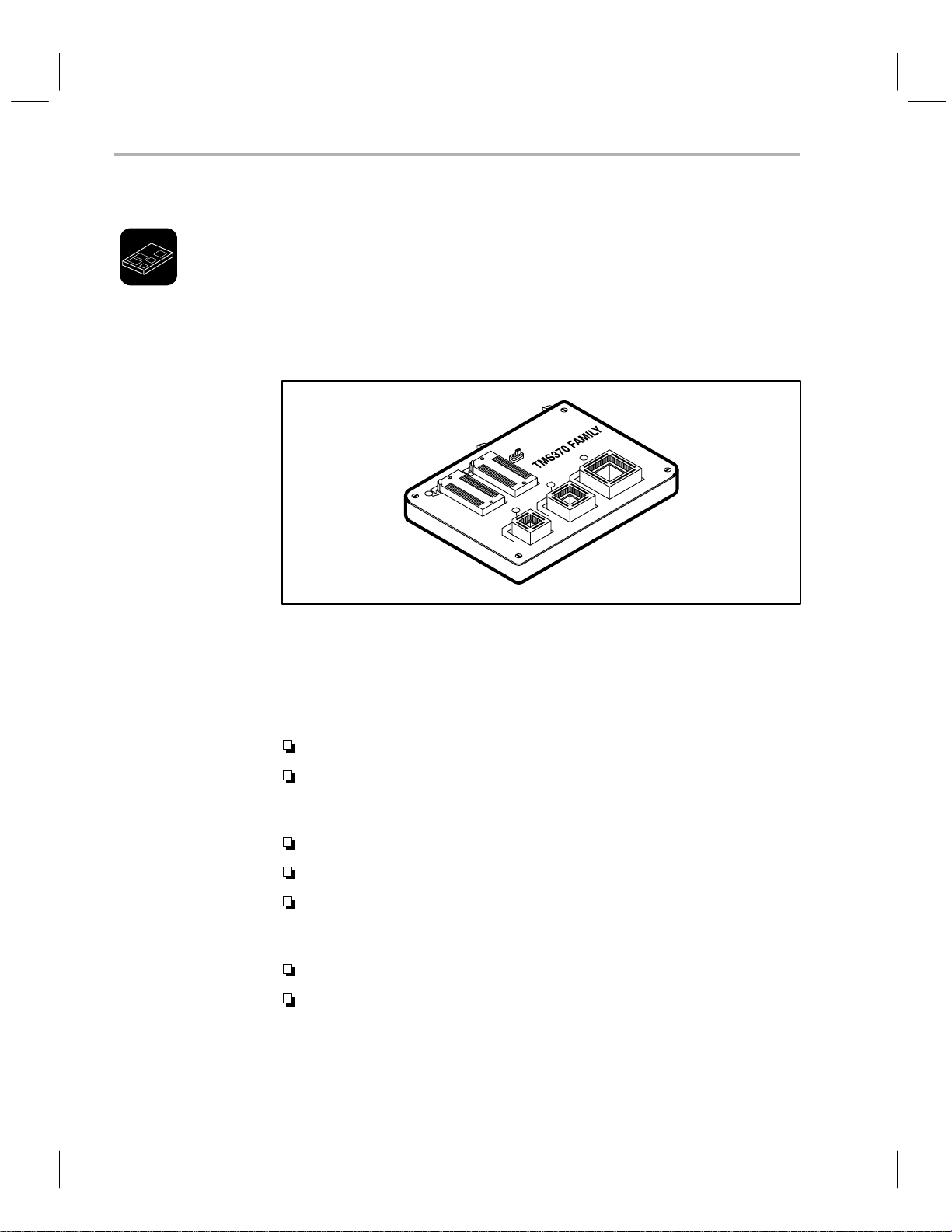
1.1 Microcontroller Programmer Overview and Description
The TMS370 Microcontroller Programmer is an interactive, menu-driven system that facilitates programming TMS370 family devices and EPROMs either
directly or through an XDS. The microcontroller programmer is currently
capable of programming the TMS370, TMS7742, TMS77C82, 2732, 2764,
27128, and 27256 device families. T o program the TMS7742 and TMS77C82
devices, you will need a 40-pin to 28-pin converter, which is sold separately.
Figure 1–1. Microcontroller Programmer Personality Module
T o operate the programmer , create a COFF file using the TMS370 Assembler
and Linker on a PC. The programmer loads the object code from the COFF
file into PC memory and programs a device from the data in PC memory . The
device is programmed and verified in units (packets) of 180 bytes at a time.
The programmer software has the following features:
Window-oriented screens with a menu-driven command structure.
Intermediate PC memory , which provides a storage area for downloading
a COFF file or uploading from the device. This allows you to inspect and
patch the loaded data.
Reversed assembly code display.
Ability to generate a COFF file from PC memory content.
Relocatable programming capability, which allows source data bytes
within a certain address range to be programmed at a specified location
in the device.
User-defined device types that allow new family members.
Ability to save or load the programmer configuration to or from a
configuration/batch file
In addition to these features, a limited batch mode is also supported.
.
1-2
Introduction and Installation
Page 17

Microcontroller Programmer Overview and Description
The base unit of the programmer contains two LEDs. The red LED is marked
program
sockets. The green LED is marked
or
device power
and is lit whenever power is applied to device
power
and indicates that the base is turned
on. This LED should turn on approximately three seconds after power is
supplied to the programmer.
Do not insert or remove devices from the programmer while the red
program (device power)
LED is lit!
On the front edge of the programmer base is a black banana plug receptacle.
This is attached to the safety ground of the power cord in order to assist you
in connecting to electrostatic protection equipment.
1-3
Page 18
Gang Programmer Overview and Description
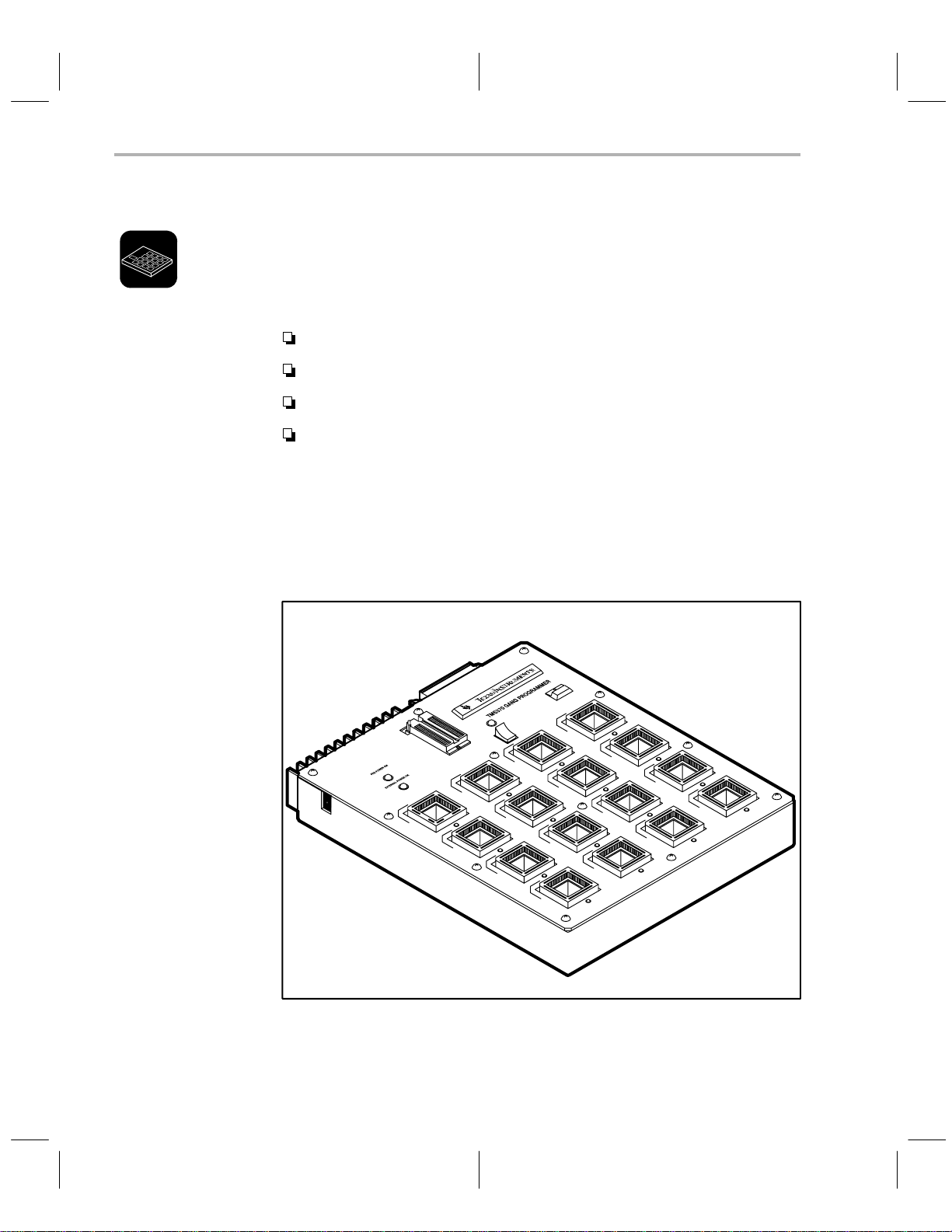
1.2 Gang Programmer Overview and Description
The TMS370 Gang Programmer is an interactive, menu-driven system that
provides programming support for on-chip EEPROM or EPROM of TMS370
microcontrollers in production environments.
The gang programmer has the following features:
Two modes of operation—PC mode and standalone mode.
Ability to program up to 16 devices.
LEDs that indicate programming or verification failure.
A buzzer that indicates programming completion.
The gang programmer consists of the standard programmer base, a gang programmer top, and the standard programmer software. If you already have a
standard TMS370 Microcontroller programmer, the gang programmer top can
be purchased separately . (There is a different programmer top for each package of TMS370 microcontrollers.)
Figure 1–2. Gang Programmer Board
1-4
The push-button switch in the upper right-hand corner is marked
used to start and stop programming or verification while operating in the stand-
Introduction and Installation
start
and is
Page 19

Gang Programmer Overview and Description
alone mode; it is ignored in PC mode. The red LED built into this switch is
marked
TMS370 power on
and indicates that power is being supplied to the
sockets on the gang programmer.
Do not insert or remove devices from the programmer while the red
TMS370 power on
LED is lit!
The main body of the gang programmer consists of 16 sockets whose type and
arrangement are dependent on the type of gang programmer top you have.
Below each socket is a red LED, which is used to indicate a failure of the device
in the socket immediately above the LED. These sockets are mounted on base
sockets to allow easy replacement if a socket is damaged.
The rocker switch on the top center of the gang programmer board is used to
select program or verify when used in standalone mode; it is ignored in PC
mode. The red LED just above this switch is lit when the switch is in the program position.
There are two green LEDs on the left top of the gang programmer. The top LED
is marked
PDS power on
er LED is marked
and indicates that the base unit is turned on. The low-
external power on
and is used to indicate that the external
+15V is properly connected to the programmer top. The external power jack
is located on the upper left side of the programmer top.
Typically , this programmer is used in PC mode to program initial units. However, you can use the 28-pin DIP socket at the top center of the programmer to
program a 27C512 EPROM as a master device. As the master device is programmed, a checksum is calculated and added to the configuration information stored in the master device. This allows the programmer to verify that the
master device has not become corrupted before it is used to program additional units. Once programmed, this master contains all of the configuration data
as well as the code to be programmed into the mocrcontrollers. Now, the gang
programmer with the master device can be moved to a production environment where you can easily program parts without the use of a personal computer; this is called standalone mode.
1-5
Page 20

Gang Programmer Overview and Description
1.2.1 Operating the Gang Programmer in PC Mode
In
PC mode
facilitates programming TMS370 family devices and EPROMs. The system allows you to perform any or all of the operations listed below.
Program any or all of the 16 devices from PC memory
Modify or add a new device to the device table
Verify any or all devices against either PC memory or the master device.
Upload any of the 16 devices.
Program the 512K master device.
Upload the master device with or without configuration data.
Enter standalone mode.
When you program in PC mode, all LEDs are turned on for a predetermined
time as part of an LED test. Then, the software checks whether a device exists
in each socket and whether it is properly installed by running a small read-write
test. If any device fails, the LED for that device blinks for a few seconds, there
are two short audible beeps, and the following error message is displayed:
Device test failed, continue? (y/n)
, the gang programmer is an interactive, menu-driven system that
If you have incorrectly inserted any device(s), you can fix them at this time. If
only empty sockets failed, you can continue the programming by pressing
The LED of the failed device(s) remains on during programming. At the end
of programming if there is a verification error on any other device, its LED turns
on also.
In the PC mode, the push button on the gang programmer is deactivated. The
interactive commands for this mode are discussed in Chapter 2 and 3.
The gang programmer’s ability to execute any or all of the programmer commands on a
master
device allows you to program a master device for use in
standalone mode or to verify programmed devices against the master device
or PC memory while in PC mode.
1.2.2 Operating the Gang Programmer in Standalone Mode
In
standalone mode,
access the stanalone mode from the PC mode by selecting the standalone
command; when the PC is not connected to the Gang Programmer during
power-up, standalone mode is automatically selected.
Standalone mode allows you to program and/or verify devices in a productiontype mode.
After you install the master 512K EPROM device and any devices you wish to
program or verify, the procedure for starting the programmer is quite simple.
the programmer works without the PC interface. Y ou can
.
1-6
Introduction and Installation
Page 21

Gang Programmer Overview and Description
1) Position the toggle switch to either the program position or the verification
position.
2) Press the push button on the programmer.
While you press the push button, all 16 LEDs turn on, and remain on to
verify LED operation, until you release the push button.
3) Release the push button to begin the programming or verification.
If any of the devices are bad or incorrectly inserted into a socket or if the
socket is empty, the programmer beeps twice, and the LED below the
socket begins blinking.
4) To resume programming/verification, press the push button (within a
2-second period).
5) If you want to correct the error, wait until the blinking LEDs stop blinking
but remain on. At this time, insert a new device (or reinsert the old device)
and try the programming/verification procedures again.
6) Once programming has begun, you can abort at any time by pressing the
push button.
If you try to program without a master or with an invalid master device, all 16
LEDs blink until you acknowledge the error by pressing the push button.
1-7
Page 22
Properly Installing the Programmer Hardware
1.3 Properly Installing the Programmer Hardware
Correctly installing the programmer hardware is essential to the proper operation of programmer system. The following subsections explain how to connect
the programming board to the PDS base unit and the required power connections for connecting your programmer to a PC or TMS370 XDS. Also included
in these subsections is a description of how to properly insert DIPs and PLCCs.
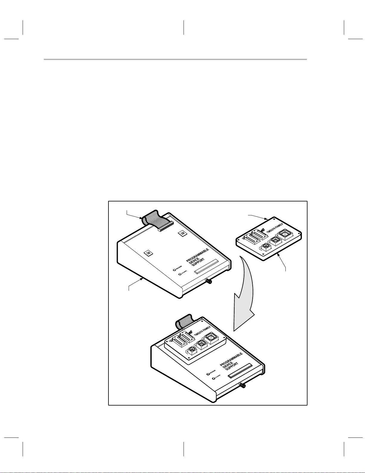
1.3.1 Connecting a Programmer to the PDS Base Unit
Connecting the programmer to the PDS is essentially the same for all programmers. The illustrations below show this process for the microcontroller programmer.
1) Line up the plastic tabs on the bottom of the programmer board with the
insertion hole in the top of the PDS base unit.
2) Press firmly until tabs are set.
3) Connect the ribbon cable from the PDS base unit to the connection on the
back of the programmer.
ribbon cable
ribbon
cable
connection
1-8
microcontroller
programmer
PDS base unit
connected PDS base
unit
and programmer board
Introduction and Installation
Page 23
1.3.2 Power Connection
The gang programmer also requires an external power supply of 15 volts/2
amps. The connection for this external power is marked EXTERNAL POWER
and is positioned near the top left corner of the programmer’s socket board.
Plug the the jack of the +15-volt wire into the external power socket. Connect
the white-striped wire to the +15-volt terminal of the power supply and the solid
black wire to the ground terminal of the power supply.
Properly Installing the Programmer Hardware
Connect the female end of the power cord to the PDS base unit.
The programmer can handle a power range of 105 to 265 volts AC at 47
to 440 hertz. All units are equipped with two power cords. If you are in the
U.S.A., use the power cord with a male connector that can be plugged
directly into a 120-V, 60-Hz power socket.
Outside the U.S.A., use the power cord with no male connector because
the type of receptacle to be used is unknown. Attach the appropriate connector for your power receptacle. The wires are color coded as follows:
Green and Yellow = Earth
Blue = Neutral
Brown = Live
1.3.3 Connection to a PC
1) Connect the end of the RS-232C cable consisting of a single 25-pin connector to the programmer.
2) Connect the end of the RS-232C cable consisting of two 25-pin
connectors to the serial communication port of the PC. (If an IBM PC/A T
is used, the 9-pin-to-25-pin converter cable provided must be used.)
1.3.4 Connection to an XDS
Connect the programmer through an XDS if you want to use both the XDS
Debugger and the microcontroller programmer, and if the PC has only one
communication port. Or, even if you have enough communication ports but do
not want to change the port number when you switch from one tool to the other,
you can use this method. The programmer works as if it is connected directly
to the PC.
Complete the following steps to connect the programmer through an XDS.
1) Connect port D of an XDS to the programmer by using the RS-232C cable
supplied with the programmer. The male connector on the double-headed
end of the cable connects to the XDS; the single-headed end connects to
the programmer.
1-9
Page 24

Properly Installing the Programmer Hardware
2) Connect port A of the XDS to the PC by using the cable supplied with the
XDS.
3) Ensure that the switches on the XDS Communications board are set as
in Table 1–1.
Table 1–1. XDS Memory Expansion/Communications Board Switch Settings
Switch No. S1 S2 S3 S4
1 Off Off Off Off
2 Off On Off Off
3 Off Off Off Off
4 Off On On Off
5 On Off On On
6 Off Off On On
7 On On On Off
1-10
Introduction and Installation
Page 25
1.3.5 Integrated Circuit (IC) Insertion
ICs may be inserted or removed while power is applied to the programmer;
however:
1) When using the microcontroller programmer, never use
more than one IC socket at a time. Damage to the IC or the
programmer could result.
2) Never insert or remove the IC while the red LED is on. Dam-
age to the IC or the programmer could result.
3) TMS devices contain circuits to protect their inputs and out-
puts against damage due to electrostatic discharges of up to
2 kV. However, you should employ the usual precautions
when handling MOS devices, such as storing the device in
conductive foam and grounding yourself when handling
them.
For the microcontroller programmer, decide which of the sockets (U1, U2, U3,
U4, or U5) to use for your device. Figure 1–3, shows the circuit board and IC
sockets.
Properly Installing the Programmer Hardware
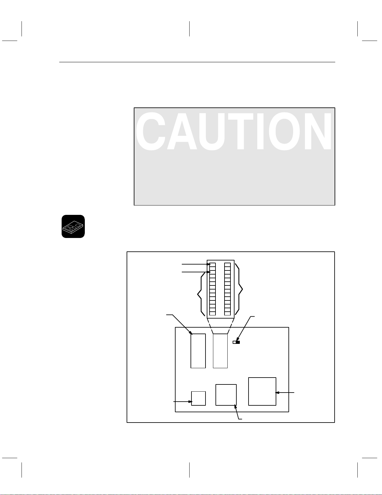
Figure 1–3. Socket Identification
2764, 27128, and 27256
370Cx10 DIP
370Cx10 PLCC
2732 pin 1
pin 1
pin 1
2732
J2
U1 U2
U3 U4 U5
2764
27128
27256
Set to left for 2732
Set to right for 2764, 27128,
{
and 27256
370Cx32 PLCC
370Cx5x PLCC
1-1 1
Page 26
Properly Installing the Programmer Hardware
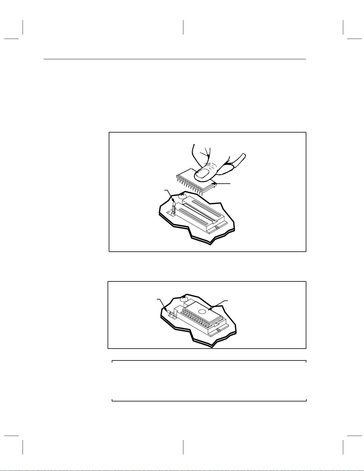
To install a DIP device:
1) Align the IC so that pin 1 is oriented in the upper-left corner, indicated on
the printed circuit board by a circled number 1:
2) Raise the locking arm, pulling it toward you to the upright position.
3) Insert the IC.
locking arm
DIP
4) Lower the locking arm by pushing it away from you and down, as far as
it will go.
locking arm
DIP
1-12
Note:
If you install a 2732 device in U2, be sure to use the bottom socket holes,
leaving the top four socket holes unused. The correct position for a 2732
is indicated by a bracket on the printed circuit board to the left of the socket.
Introduction and Installation
Page 27
Properly Installing the Programmer Hardware
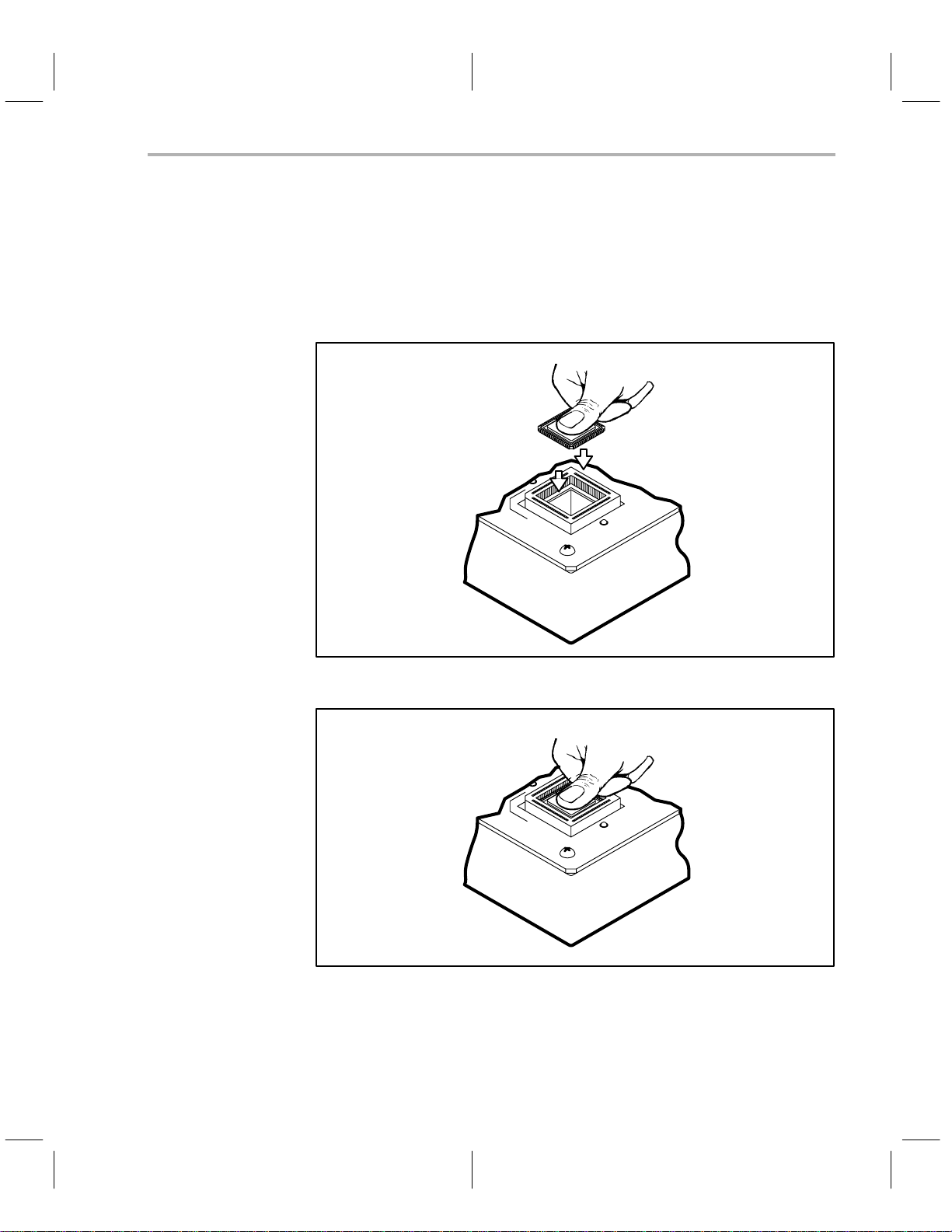
To install a PLCC device:
With this release of the programmers, the PLCC sockets do not have a lid;
therefore, they are not sensitive to the device package height. These new
sockets also have the pin 1 orientation at the top of each socket, making it less
likely for you to insert a device backwards.
1) Place the PLCC in the empty socket.
2) Press firmly until it is properly seated.
The programmer hardware is now ready to use.
T o remove the device, press down firmly on the black plastic socket edges until
the device is pushed upward and released.
1-13
Page 28

Properly Installing the Programmer Software
1.4 Properly Installing the Programmer Software
Installing software is exactly the same whether you are using the Microcontroller Programmer or the Gang Programmer. Insert the diskette supplied with the
programmer into the PC disk drive and use one of the following methods to
copy the contents of the diskette to a directory in your hard disk.
1.4.1 Installing the Software in a Single Directory
This method is simple and suitable for a single user with only a few source files.
1) Make a directory to contain your programmer files.
MKDIR \370
2) Change your working directory to the directory you just created.
CD \370
3) Copy the files from the diskette.
COPY A:*.*
4) See Section1.5 for a description of how to invoke the programmer software.
1.4.2 Installing the Software in Multiple Directories
This method is useful if there are several different users or if one user is working on several different projects.
1) Create a directory for your programmer files.
MKDIR \370
2) Copy the programmer files into your programmer directory:
COPY A:*.* \370\*.*
3) Create project directories.
MKDIR \PROJ1
MKDIR \PROJ2
4) Add the programmer directory to the path command in the AUTOEXEC.BAT file.
PATH C:\DOS;C:\PROG;C:\REP;C:\370
where C:\370 is the added path to the programmer directory.
set
5) Include a
SET IPCDIR=C:\370
If the
device table
the programmer to search the programmer directory for the default device
command in the AUTOEXEC.BAT file as follows:
cannot be found elsewhere, the
set
command causes
1-14
Introduction and Installation
Page 29

Properly Installing the Programmer Software
table. The order in which the programmer looks for the device table is outlined below.
a) First, it looks for a device table file specified in the configuration/batch
file if the configuration/batch file was included in the command line to
invoke the programmer software.
PRGRM370 @PROJ1.CFG
where PROJ1.CFG is the configuration/batch file.
b) Next, it looks in the current directory for the default DEVICE.TBL.
c) Then, it looks in the directory specified by the ”SET IPCDIR” command
for the file DEVICE.TBL.
6) See Section 1.5 for a description of how to invoke the programmer software.
1-15
Page 30

Invoking the Programmer Software
1.5 Invoking the Programmer Software
Before activating the programmer, be sure that it is plugged in and correctly
connected as described in Section 1.3. Turn on the programmer’s power
switch (and the gang programmer’s external power) before invoking the programmer software.
The command to run the programmer software from the DOS prompt is:
prgrm370 [
COFF file
] [@
Config./Batchfile
] [–b] [–p=
port #
]
where
COFF file
Optional argument that specifies a file to be programmed or verified in the batch control mode or
loaded into PC memory in the interactive control
mode.
Config./Batch file
@
Optional argument that specifies a configuration/
batch file that contains the configuration parameters or the batch commands for the batch control
mode.
–b Optional argument that turns on the batch mode if
specified.
–p =
port #
The communication port number to be used. Default is 1.
After you invoke the programmer software, the PC screen briefly displays a
version number and copyright message.
If you specified a configuration/batch file but did not turn on the batch mode,
the configuration specified in the file is loaded as the current configuration. Any
other batch commands that would control the flow of the programming process
are ignored.
If you specified a configuration/batch file and turned on the batch mode with
the –b argument, the programmer software operates as directed by the batch
file.
1-16
If you specified a port number and the programmer is not physically connected
to that port, then the following error message is displayed.
Programmer not properly connected: Abort, Retry?
Aborting the invocation returns you to the DOS prompt. T o retry the invocation,
make sure the programmer is turned on and properly connected to the port
specified in the command. Then, press
followed by to restart the
programmer software.
Interactive mode commands are described in detail in Sections 2 and 3. Batch
commands are covered in Appendix 1.
Introduction and Installation
Page 31

1.6 Getting Started—Example Sessions
This section will help you get a quick start using your programmer. Once you
get started, the menu structure and prompts make the programmer easy to
learn and to use. The remainder of this manual provides a detailed reference
if you need further information on any of the commands, prompts, or error
messages. Use the T able of Contents at the front of the manual and the Index
at the end of the manual to direct you to the specific topic you need.
We assume that you are familiar with the TMS370 Assembler and Linker software and that a COFF file has been created that contains object code with
which a device can be programmed. These are prerequisites to using the
programmers and is beyond the scope of this manual.
1.6.1 Interactive Programming Example 1
This example assumes that the programmer software has been loaded onto
your PC, and that the DOS prompt is C:>.
In this example you will invoke the programmer, choose a device to program,
and use the
and portion of the object code to be programmed onto the device.
load
command to give the programmer the name of the object file
Getting Started—Example Sessions
1) From the DOS prompt, invoke the programmer to bring up the interactive
display in the configuration window.
C:\>prgrm370
The programmer title banner appears briefly; then the configuration
window appears with the top line containing the following command menu:
CONFIG:showID AddDevice Edit Load ChooseDevice Save Display Quit
2) Place a TMS370 device in the appropriate socket; press to select the
choose device command.
The cursor moves down the screen to the beginning of the Device Table.
Also, a function key command line containing the following commands
appears at the bottom of the screen:
F1NextPage F2PrevPage F4ShowRanges F5SelectDev F6DeleteDev
3) Move the cursor to the appropriate device using the cursor arrow keys.
Once you have found the correct device, press
4) Press
to return to the configuration command line, and then press
to select the device.
to move to the display window.
The display window command line contains the following commands:
Fill Load OutputCOFF Move Progm Show Upload Verify Edit Config sYs Quit
5) Press for the load command. The following prompt appears at the top
line of the screen:
1-17
Page 32

Getting Started—Example Sessions
Object file:
6) Enter the name of the COFF file containing the object code with which the
device is to be programmed. Press
Object base address: all
where
is to be used.
, and the following prompt appears:
all
is the default, meaning that the entire object code address range
7) Select the address range default of
all
by pressing .
The cursor returns to the display window command line.
8) Press
to start the programming process. A prompt appears, asking for
the name of a file in which programming errors are to be recorded.
Error file:
9) Enter a file name and press .
10) A prompt appears, asking for the starting address in PC memory of the
data to be used in programming.
PC memory base address: all
11) Accept the default all by pressing .
12) Programming begins, and the bottom line of the screen is replaced by a
status message informing you of the beginning address of the packet (180
bytes) currently being programmed. This line will be replaced by an error
message if an error should occur. Otherwise, when programming is complete, the bottom line of the screen shows a prompt asking if another device is to be programmed using the same parameters.
Programming Complete, Program another device? (y/n)
Press n and then to terminate programming and return to the display
window command line. The device is now programmed and verified, as-
suming no error messages appeared.
1-18
Introduction and Installation
Page 33

1.6.2 Interactive Programming Example 2
This sample session illustrates entering the interactive mode with the COFF
file automatically loaded into PC memory . If the programmer software is active,
that is, in the display or configuration windows, press
mer and verify your choice. This returns the DOS environment.
1) At the DOS prompt, type the following command:
C:\>prgrm370 xyz.out
where
xyz.out
which the device is to be programmed.
is the name of the COFF file containing the object code with
Getting Started—Example Sessions
to quit the program-
2) Press
. The programmer software will start and automatically load the
code in the xyz.out file into PC memory.
You can now operate the programmer in the interactive mode as usual.
This method saves a few steps in loading the COFF file if the default load
addresses are acceptable.
1.6.3 Batch Programming Example
This sample session illustrates batch mode programming. A configuration/
batch file (not to be confused with a DOS batch file) must exist in order to use
this method. If one does not, examine the detailed description in Appendix 1.
For this example, assume that your configuration/batch file is named abc.cfg.
If the programmer software is active, that is, in the display or configuration
windows, press
you to the DOS environment.
At the DOS prompt, type the following:
C:\>prgrm370 xyz.out @abc.cfg –b
where
xyz.out
@ symbol is a delimiter identifying abc.cfg as a configuration/batch file, and
–b
symbol turns on the batch mode. If the –b had been left off, the interac-
the
tive mode would have been entered, and the configuration specified in the
abc.cfg file would be used.
is the COFF file and
to quit the programmer and verify your choice. This returns
abc.cfg
is the configuration/batch file. The
For more information on the batch mode, see Appendix 1.
1-19
Page 34

1-20
Introduction and Installation
Page 35

Chapter 2
Operating in the Configuration Window
This chapter describes the commands offered in the configuration window of
the programmer’s display.
The first part of this chapter explains how the command menus and function
keys work; it also has a short section on entering information at the cursor
prompt.
have already read these sections in Chapter 3, there is no need to read them
in this chapter.
The remainder of this chapter describes the operation of the configuration window and explains each configuration command, walking you through the interactive display prompts where applicable.
Section Page
2.1 How the Command Menus Work 2-2. . . . . . . . . . . . . . . . . . . . . . . . . . . .
2.2 Using the Special Function Keys 2-3. . . . . . . . . . . . . . . . . . . . . . . . . . . .
2.3 What Happens If I Make an Error? 2-3. . . . . . . . . . . . . . . . . . . . . . . . . .
2.4 Understanding Your Input at the Cursor Prompt 2-4. . . . . . . . . . . . . . .
2.5 Configuration Window Overview and Description 2-5. . . . . . . . . . . . .
2.6 Secondary Configuration Window—the Show
2.7 Showing the Software Revision Information 2-9. . . . . . . . . . . . . . . . . .
2.8 Defining and Adding a Device to the Device Table 2-9. . . . . . . . . . . .
2.9 Editing the Configuration Parameters and Device Table 2-11. . . . . . .
2.10 Loading the Device Table and Configuration Parameters
2.11 Selecting a Current Device 2-15. . . . . . . . . . . . . . . . . . . . . . . . . . . . . . . .
2.12 Saving Configuration Parameters and the Device Table
2.13 Showing the Display Window 2-16. . . . . . . . . . . . . . . . . . . . . . . . . . . . . .
2.14 Ending Your Current Session and Returning to DOS 2-16. . . . . . . . .
These sections are the same as the initial sections in Chapter 3; if you
Ranges Window 2-7. . . . . . . . . . . . . . . . . . . . . . . . . . . . . . . . . . . . . . . . . .
From a File 2-14. . . . . . . . . . . . . . . . . . . . . . . . . . . . . . . . . . . . . . . . . . . . .
to a File 2-15. . . . . . . . . . . . . . . . . . . . . . . . . . . . . . . . . . . . . . . . . . . . . . . .
2-1
Page 36

How Command Menus Work
2.1 How Command Menus Work
The interactive mode of the programmer is driven by
displayed on the top line of the screen. A command menu is a list of command
names, each of which is displayed with one highlighted letter, usually the first
character in the name. The highlighted letter is the key you use to invoke the
command. You may type command letters in upper or lower case.
When you type a valid command letter, the programmer software clears the
command line, displays the name of the selected command, and executes the
command. Most commands require additional information, in which case the
programmer either prompts for parameters or displays a submenu of commands.
Figure 2–1 shows the command menu structure. This figure is provided as a
road map to the desired command(s).
Figure 2–1. Command Menu Structure
D
showI
prgrm370
Config file
specified?
No Yes
command menus
Fill
Load
Output COFF
that are
2-2
dd Device
A
dit
E
Load
hoose Device
C
S
ave
D
isplay
Q
uit
Command
Windows
Config
Move
Prgrm
Display
Show
Upload
Verify
Edit
Config
sYs
Quit
Operating in the Configuration Window
Page 37

Using the Special Function Keys/What Happens If I Make an Error
2.2 Using the Special Function Keys
Function keys through invoke various actions in the programmer,
depending on your location in the command menu structure. The valid function
keys and their definitions for each mode are displayed on the bottom line of
the screen for reference. Press the highlighted key for the desired action.
Another special function key is
return to the next higher command menu level, press this function key . For ex-
ample, if you are in the
command menu.
fill memory
2.3 What Happens If I Make an Error?
If an error occurs, the programmer software displays an error message on the
bottom line of the screen and prompts you to
error state. You can type any key, including
sage is then cleared, and the function key line is redisplayed.
If the error was caused by an input to a prompt, the programmer software re-
turns to the prompt to let you re-enter a value. Otherwise, the software returns
to the next higher command menu.
To find an explanation of any error message, refer to Appendix 2.
. If you ever need to abort a command and
command, press to return to the display
hit any key
, on the keyboard. The mes-
to escape from the
2-3
Page 38

Understanding Your Input at the Cursor Prompt
2.4 Understanding Your Input at the Cursor Prompt
The programmer software often requires you to enter a response to a prompt
or to move the cursor to a value on the screen and modify it.
The previous or default value for the prompted parameter value is always displayed. Y ou can accept the displayed default or former value by pressing only
in response to the prompt.
If you type a new value, the characters are highlighted, and the cursor advances to the next field position.
by the programmer
020 (the underscored character indicates the cursor position). If you type 8
7
. For example, assume that the displayed default value is
over the default value, you would see 80
acter indicates the highlighted character on the screen). If you then pressed
the ENTER key, the value entered would be 0008,
All numeric input values are hexadecimal except for the VCC, VPP, and
program-pulse-duration-time values, which are decimal.
T able 2–1 lists special control keys. The effect of each key is given for both text
and numeric fields. Any control key not listed in the table has the same effect
.
as
Only the highlighted characters are accepted
20 on the screen (the boldface char-
not
8020.
Table 2–1. Edit Control Keys
Key Function
Terminates input and accepts current value.
Text: Inserts a space.
Numeric: Terminates input and accepts current value.
T ext: Erases character to the left of cursor and backs up one space.
Numeric: Erases character to the left of cursor and backs up one space.
T ext: Subsequently typed characters are inserted at the cursor posi-
tion; characters to the right of the cursor are moved right, even
out of the field. Remains in effect until the INSERT key or
another control key is typed.
Numeric: No effect.
Text: Deletes character at cursor.
Numeric: No effect.
Text: Moves cursor left one space without erasing.
Numeric: Moves cursor right one space without erasing.
Text: Moves cursor right to the next character and highlights it.
Numeric: Moves cursor right to the next character and highlights it.
2-4
Operating in the Configuration Window
Page 39
Configuration Window Overview and Description
2.5 Configuration Window Overview and Description
If you use the
configuration
command while in the display window, the config-
uration window illustrated in Figure 2–2 is displayed; it also displays when
the programmer software is first invoked.
Figure 2–2. Configuration Window at System Startup
CONFIG:
Program Configuration
Port#: 1
Device Type
27128 TMS27C128
27256 TMS27C256
2732 TMS2732A
2764 TMS2764
7742 TMS7742
TMS370 16K_PE
Show D ddDevice dit oad hooseDevice ave isplay ui
t
TMS27C64
256_DEE
4K_PEE
512_DEE
C010
C050
The configuration window consists of three different areas—a command line,
a program configuration area, and the device table.
AEL DQC SI
command line
The
the data in the configuration window. These commands are listed in Table 2–2
and described in detail in Sections 2.7 through 2.14.
Table 2–2. Configuration Window Commands
Command Function
Show ID Display software title and revision level.
Add Device Add a new device to the device table.
Edit Edit the configuration parameters.
Load File Load current configuration or current device table from a file.
Choose Device Choose (set) the current device type.
Save File Save the current configuration or the current device table in a file.
Display Go to the display window.
Quit Quit (exit) and return to DOS.
The
program configuration area
tion port—port 1 or 2. To change this value, refer to Section 2.9.
lists the available commands you can use to manipulate
lists the current selection of the communica-
2-5
Page 40

Configuration Window Overview and Description
The
device table
lists devices that can be programmed through the programmer. The device table displays 12 device types at a time and is sorted first by
the device family names and then by the device first names. If there is more
than one device type under one device family, the family name is displayed
only once, on the first line of the device family . When a new device is specified
or a device table is loaded from an outside file, the device table is automatically
updated. If the actual device table contains more than 12 device types, you can
use the function keys to scroll through the table. When a current device is selected, it is highlighted within the table.
The device table supplied with your programmer software includes all of the
TMS370 devices available at the time the programmer was produced. As new
configurations are made available, TI updates the DEVICE.TBL file and
makes it available through our microcontroller bulletin board system. For information on how to use the bulletin board, contact the TMS370 hotline at the
number indicated on page 1-1.
2-6
Operating in the Configuration Window
Page 41

Secondary Configuration Window—the Show Ranges Window
2.6 Secondary Configuration Window—the Show Ranges Window
A small subwindow appears when you select the
, from the device area of the configuration window. Figure 2–3 illustrates
what the show ranges
Figure 2–3. The Show Ranges Window
CONFIG:
Program Configuration
Port#: 1
Device Type
27128 TMS27C128
27256 TMS27C256
2732 TMS2732A
2764 TMS2764
7742 TMS7742
TMS370 16K_PE
The show ranges window does not neccesarily default to show the ranges of
the chosen device. Instead, it shows the ranges of the device that the cursor
is next to in the device table. Y ou can scroll through the device table and notice
the parameters changing in accordance with each new device the cursor is
next to.
ChooseDevice
Valid address ranges for 2732/TMS2732A
START SIZE TYPE Vcc Vpp Pdt CtrlReg FmlyCode BlkErase Pbits
00000h 1000h EPROM 5 21 10 ooh 40h NO O’s only
TMS27C64
256_DEE
4K_PE
512_DEE
C010
C050
window looks like.
show ranges
function key,
Table 2–3. Show Ranges Parameter Summary
Parameter Description
Start Valid start address for programming.
Size Size of the valid program area.
Type The type of memory in this range (EEPROM or EPROM).
V
CC
V
PP
pdt Program pulse duration time.
ctrlReg The control register.
FmlyCode The hexadecimal family code of the device.
Blk-Erase The block erase toggle.
†
Pbits
†
The program algorithms are discussed in detail in subsection 2.6.1.
Valid Vcc values are 0, 5, or 6 volts.
Valid Vpp values are 0, 5, 12, 12.5 or 21 volts.
The program algorithm.
2-7
Page 42

Secondary Configuration Window—the Show Ranges Window
2.6.1 Selecting the Proper Program Algorithm
For EEPROM memory in devices, there are three programming modes:
writing 0s only, all 1s in the data bytes are ignored.
writing 1s only, all 0s in the data bytes are ignored.
writing 0s and 1s.
For all other types of memory,
writing 0s
is the only programming mode.
The three modes provided for the TMS370 allow the selection of the most
efficient programming.
When the 1s and 0s mode is used, the programmer makes two passes through
the address range, programming the 1s in one pass and the 0s in the other
pass. Assume that the binary value 1010 1010 is to be programmed into a given address. First, the 1s are programmed, giving a value of
1x1x1x1x
where
x is unknown (the previous contents of the location).
On the second pass, the 0s are programmed, resulting in
x0x0 x0x0
where x
is a don’t care state (in this case 1s from the first pass) so that the resulting
value after both passes is
1010 1010
, the desired value. This method is effec-
tive for modifying short segments of code.
If a large segment of code is to be modified, it will reduce programming time
by almost one half if you block erase to 1s and use the 0s-only mode.
When programming the EEPROM memory of TMS370 devices that also have
UV-erasable EPROMS, be sure to block erase the array before programming
the device. (Ultraviolet light causes the EEPROM bits to go to an intermediate
so that they must be block erased before programming.)
2-8
Operating in the Configuration Window
Page 43

Showing the Software Revision Information/Defining and Adding a Device to the Device Table
2.7 Showing the Software Revision Information — the Show ID Command
This command displays the software release/revision information on the top
line of the PC screen for reference. Press any key to return to the configuration
command line.
2.8 Defining and Adding a Device to the Device Table—the Add Device
Command
This command lets you define a new device type different from those in the
current device table, and then add it to the device table. When the
command is selected, the following programmer prompts appear.
Step 1: Identify the complete device name by answering the following two
prompts:
Device family name:
Device first name:
Legal device family names supported by the programmers are
TMS370, 2732, 2764, 27128, or 27256.
add device
Device first names are names that distinguish different versions of
the same device family.
The programmer software checks the device table to make sure the
new device is not a duplication. If the new device is a duplicate, the
following error message is displayed.
duplicate device name (hit any key)
Press any key to erase the error message and return to the first
prompt to re-enter different device names.
Step 2: Identify the programming address range by answering the following
two prompts:
Device Program Ranges – Start Address: 0000h
Device Program Ranges – Size: 0000h
Enter numerical values within the range (0000h–FFFFh) to the address prompts listed in Step 2.
Step 3: Identify the primary configuration parameters for the device by an-
swering the following four prompts:
Type of Memory:
Device VCC(in VDC – 0, 5 or 6) : 0
Device VPP (in VDC – 0, 5, 12, 12.5 or 21): 0
Program Pulse Duration time (in ms – [0–127]): 0
2-9
Page 44

Defining and Adding a Device to the Device Table
Valid types of memory are EPROM or EEPROM.
Legal V
values are listed following the prompt—0, 5, or 6. If you
CC
enter a value that is not one of the three valid choices, the following
error message appears:
invalid VCC value: 0, 5, or 6 (hit any key)
Press any key to erase the error message and return to the prompt
to enter the V
Legal V
PP
value again.
CC
values are listed following the prompt—0, 5, 12, 12.5, or
21. If you enter a value which is not one of the five choices, the following error message appears:
invalid VPP value: 0, 5, 12, 12.5 or 21 (hit any key)
Press any key to erase the error message and return to the prompt
to enter the V
Valid
pdt
values fall in the decimal range of 0–127 as shown at the
value again.
PP
end of the prompt. If you enter a value that is out of the range, an error
message is displayed as follows:
invalid Program Pulse Duration time: [0..127]
Press any key to erase the error message and return to the prompt
to enter the Program Pulse Duration time again.
Step 4: Identify the secondary configuration parameters by answering the
following four prompts:
2-10
Control Register:
This parameter is necessary only for programming TMS370 microcontrollers. The current valid values are 01Ah for the data EEPROM
range and 1Ch for the program memory range.
Family Code:
This parameter tells the programmer how to program the device. The
current valid values are:
Code Device Code Device
10h TMS370 EEPROM range 41h 2764, 27C64, SE77C42,
11h TMS370 EPROM range 42h 27C128
20h TMS7742 43h 27C256
40h 2732
Block Erase:
TMS77C82
Using the block erase parameter for devices with a family code of
10h (TMS370 EEPROM range) allows the array to be erased to 1s
or 0s. The block erase parameter is ignored for any other family code
none
and should be set to
for clarity.
Operating in the Configuration Window
Page 45

Editing the Configuration Parameters and Device Table
Program Algorithm:
If the family code is 10h (TMS370 EEPROM range), one of three programming algorithms can be chosen—
program 1s and 0s.
parameter, you can optimize for programming speed or can minimize the number of write erase cycles. This parameter is ignored for
any other family code and should be set to
After you have entered the program algorithm, the programmer repeats
the setup configuration starting at Step 2 to allow you to enter up to five
address blocks. Press
address blocks you need. You must enter at least one set of
parameters before exiting the command, or else the following warning
message is displayed.
Device parameters not complete, device not added.
Press any key to erase the warning message and return to the configuration command menu.
After you have entered all of the above parameters correctly , the newly defined device is added to the current device table and displayed in the device table window.
Using this parameter along with the
to exit the loop after you have entered all the
program 1s, program 0s,
block erase
program 0s only
for clarity .
add device
or
2.9 Editing the Configuration Parameters and Device Table — the Edit
Command
In the
edit
mode, you can edit the configuration
current device table.
2.9.1 Editing the Configuration Parameters
From the configuration window press for the edit command. Pressing
toggles you between the port # field and the device table, while pressing
in the port # field scrolls through the valid selections for the communication
port—port 1, or 2.
Press the key when you are finished editing the parameters to record your
changes and to return you to the configuration command menu.
Note:
In order to edit any of the current device table parameters, you must display
the parameters (show ranges) and then use the designated function key to
edit the ranges window. Refer to subsection 2.9.2 for a complete description.
port #
parameter field and the
2-1 1
Page 46

Editing the Configuration Parameters and Device Table
2.9.2 Editing the Device Table
The device table is a list of devices catagorized by
. The software diskette provides a device table file,
name
tains a list of devices and their configuration parameters. The devices and their
configurations are loaded automatically when the programmer software is invoked.
Pressing
from the
field. When this occurs, several function keys and their actions are displayed
at the bottom of the screen. (Choosing
place the cursor directly into the device table field if this field is the last one you
worked in. In other words, the
in before exiting back to the command line.)To edit the device table, use the
commands listed in Table 2–4.
Table 2–4. Device Table Edit Commands
Command Function
F1 (Page Down) Scroll forward through device table.
F2 (Page Up) Scroll backward through device table.
F3 (Next Window) Move to the communication port.
F4 (Show Ranges) Show the valid address ranges defined for the device highlighted
F5 (Select Device) Select the device next to the cursor.
F6 (Delete Device) Delete the device next to the cursor.
ESC (Escape) Return to the configuration command menu.
↑
↓
Return Key Accept the input value and move cursor to the next location on the
family name
port #
field causes the cursor to enter the device table
edit
from the command line will also
edit
command defaults to the last field you were
by the cursor.
Move up one line, scrolling if necessary.
Move down one line, scrolling if necessary.
same line.
and
device.tbl
device first
, that con-
If you press , a temporary window appears on the upper half of the screen
(as shown in Figure 2–4) that shows all the parameters of the current device.
Figure 2–4. Valid Address Ranges Window
Valid address ranges for 2732/TMS2732A
START SIZE TYPE Vcc Vpp Pdt CtrlReg FmlyCode BlkErase Pbits
00000h 1000h EPROM 5 21 10 ooh 40h NO O’s only
In order to edit these configuration parameters, press (this function key
changes from
called.) Use the editing protocol as described in Section 2.4 and the parameter
descriptions in Section 2.8 in order to customize these device parameters.
2-12
next window
to
edit ranges
when the show ranges window is
Operating in the Configuration Window
Page 47

Editing the Configuration Parameters and Device Table
Pressing causes this temporary window to disappear, and the previous
window is resumed.
Pressing
from the device table selects the device on the line where your
cursor is positioned. The device you have chosen is highlighted when selected.
Pressing
deletes the device on the line where your cursor is positioned.
If the deleted device is the current device, there is no current device type, and
you must select a new device from the device table.
2-13
Page 48

Loading the Device Table and Configuration Parameters From a File
2.10 Loading the Device Table and Configuration Parameters From a
File — the Load Command
When you select the L command, a submenu displays options for choosing a
file to load. The commands in this submenu are listed below; the letter that
invokes the command is printed in bold type.
Command Function
Device Table Load a device table file.
Configuration Load configuration parameters from a configuration/batch file.
Both load options prompt for only one parameter—the file to be loaded. If the
file specified does not exist, an error message is displayed as follows:
Can not open file: <file name> (hit any key)
Press any key to erase the error message and return to the prompt to enter
the correct file name.
If a file that is not a valid device table is specified, the following error message
is displayed:
Invalid/Wrong device table file: <file name> (hit any key)
Press any key to erase the error message and return to the configuration command menu.
Loading the Device Table
Select this option to load the current device table from a file that you
specify . The device table window is updated as the current device table is
reloaded.
Load the Configuration Parameters
This option loads the configuration parameters, listed below, from the
specified configuration file.
Communication port
Current device
Device table
If the device table file is specified, it will be loaded as the current device
table, and the device type specified in the configuration/batch file will be
searched for in the table.
2-14
Operating in the Configuration Window
Page 49

Selecting a Current Device/Saving the Configuration Parameters and Device Table to a File
2.11 Selecting a Current Device — the Choose Device Command
The
choose device
command moves the cursor directly to the device table.
Use the cursor control keys to move the cursor to the device you will be programming and press
ing
returns you to the configuration command line.
to select it. The selected device is highlighted. Press-
A device must be specified before the software allows you to enter the display
window.
2.12 Saving Configuration Parameters and the Device Table to a File — the
Save Command
The
save
command allows you to save the current configuration parameters
or device table to a specific file. The initial prompt after this command executes
gives you the following two choices; the letter used to invoke the command is
printed in bold type.
Command Function
Device Table Save the current device table in a file.
Configuration Save the current configuration in a Configuration/Batch file
Both save options prompt for only one parameter—the filename to save the
data into. The file you specify can be either an existing file or a new file. The
contents of an existing file are erased before the save takes place. The following paragraphs describe each option in detail.
Saving the Device Table
Use this option to save the current device table in a file that you specify.
The file can be loaded later through the
load device table
command or the
configuration/batch file. If the current device table is empty , no file will be
generated.
To prevent accidental overwriting of the default device table, the name
device.tbl
cannot be used for saving the current device table. If you wish to
update the default device table, save it under another name and then use
the DOS copy command to copy your new device table to
device.tbl.
Saving Configuration Parameters
Use this option to save the current configuration in a file that you specify .
The current configuration is the one defined in the load configuration section. If you have not selected a current device type, the following error
message is displayed:
No device is selected, can not build the file
Press any key to erase the error message and return to the configuration
command menu.
2-15
Page 50

Showing the Display Window/Ending Your Current Session and Returning to DOS
2.13 Showing the Display Window — the Display Command
When you choose the
to see if a current device type has been selected. If you have selected a current
device type, the programmer sets up the configuration and briefly displays the
following message before returning to the top level command.
Set programmer configuration.....
If you have
is displayed:
Warning: Device not selected, unable to set up the programmer
Press any key to erase the warning; then, use the
to select a current device. You cannot proceed to the display window until a
valid current device has been selected.
not
selected a current device type, the following warning message
display command
, the programmer software checks to
choose device
2.14 Ending Your Current Session and Returning to DOS — the Quit
Command
Use the
mer software actually quits, you must confirm that this is what you want to do
at the prompt:
Confirm:
quit
command to exit the programmer software. Before the program-
command
2-16
Press to confirm that you really want to quit. Any other key is interpreted
as a retraction of the quit command.
Operating in the Configuration Window
Page 51

Chapter 3
Operating in the Display Window
This chapter describes the commands offered in the display window of the
programmer’s display.
The first part of this chapter explains how the command menus and function
keys work; it also has a short section on entering information at the cursor
prompt.
have already read these sections in Chapter 2, there is no need to read them
in this chapter.
The remainder of this chapter describes the operation of the display window
and explains each display command, walking you through the interactive display prompts where applicable.
Section Page
3.1 How the Command Menus Work 3-2. . . . . . . . . . . . . . . . . . . . . . . . . . . .
3.2 Using the Special Function Keys 3-3. . . . . . . . . . . . . . . . . . . . . . . . . . . .
3.3 What Happens If I Make an Error? 3-3. . . . . . . . . . . . . . . . . . . . . . . . . .
3.4 Understanding Your Input at the Cursor Prompt 3-4. . . . . . . . . . . . . . .
3.5 Display Window 3-5. . . . . . . . . . . . . . . . . . . . . . . . . . . . . . . . . . . . . . . . . .
3.6 Filling a Block of PC Memory With a Value 3-8. . . . . . . . . . . . . . . . . . .
3.7 Loading a COFF File Into PC Memory 3-9. . . . . . . . . . . . . . . . . . . . . . .
3.8 Outputting a COFF File From PC Memory 3-10. . . . . . . . . . . . . . . . . .
3.9 Moving Blocks of PC Memory 3-12. . . . . . . . . . . . . . . . . . . . . . . . . . . . .
3.10 Programming a Device From PC Memory 3-13. . . . . . . . . . . . . . . . . . .
3.11 Showing and Operating Within Text File 3-17. . . . . . . . . . . . . . . . . . . .
3.12 Uploading a Device’s Contents Into PC Memory 3-19. . . . . . . . . . . . .
3.13 Verifying the Contents of a Device 3-22. . . . . . . . . . . . . . . . . . . . . . . . .
3.14 Editing the Contents of PC Memory 3-26. . . . . . . . . . . . . . . . . . . . . . . .
3.15 Using the Master Mode Menu 3-27. . . . . . . . . . . . . . . . . . . . . . . . . . . . .
3.16 Suspending the Program and Entering DOS 3-28. . . . . . . . . . . . . . . .
3.17 Quiting the Program and Exiting to DOS 3-28. . . . . . . . . . . . . . . . . . . .
These sections are the same as the initial sections in Chapter 2; if you
3-1
Page 52
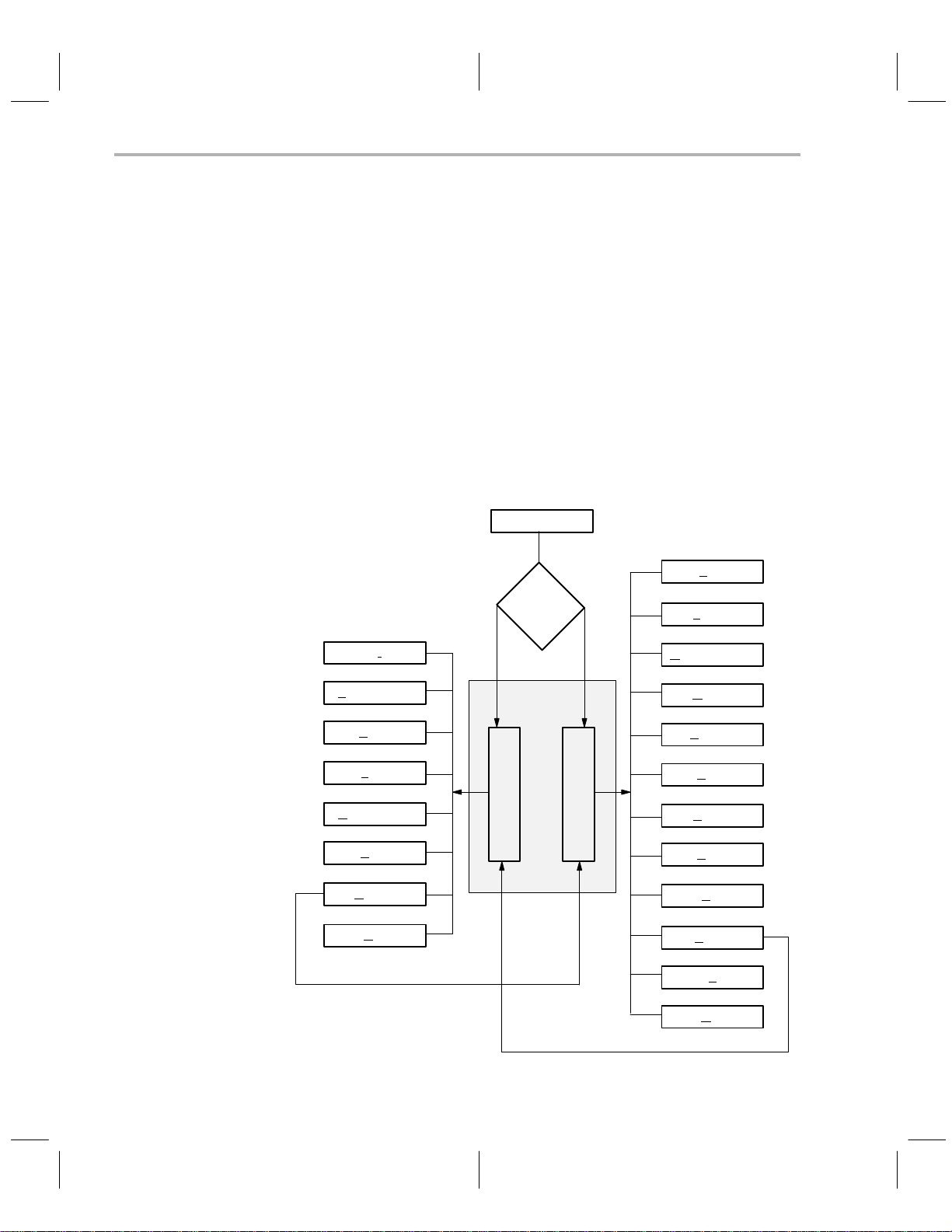
How Command Menus Work
3.1 How Command Menus Work
The interactive mode of the programmer is driven by command menus that are
displayed on the top line of the screen. A command menu is a list of command
names, each of which is displayed with one highlighted letter, usually the first
character in the name. The highlighted letter is the key you use to invoke the
command. You may type command letters in upper or lower case.
When you type a valid command letter, the programmer software clears the
command line, displays the name of the selected command, and executes the
command. Most commands require additional information, in which case the
programmer either prompts for parameters or displays a submenu of commands.
Figure 3–1 shows the command menu structure. This figure is provided as a
road map to the desired command(s).
Figure 3–1. Command Menu Structure
prgrm370
Fill
D
showI
dd Device
A
dit
E
Load
hoose Device
C
S
ave
D
isplay
Q
uit
Config file
specified?
No Yes
Command
Windows
Config
Display
Load
Output COFF
Move
Prgrm
Show
Upload
Verify
Edit
Config
sYs
Quit
3-2
Operating in the Display Window
Page 53

Using Special Function Keys/What Happens If I Make an Error?
3.2 Using the Special Function Keys
Function keys through invoke various actions in the programmer,
depending on your location in the command menu structure. The valid function
keys and their definitions for each mode are displayed on the bottom line of
the screen for reference. Press the highlighted key for the desired action.
Another special function key is
return to the next higher command menu level, press this function key . For ex-
ample, if you are in the
command menu.
fill memory
3.3 What Happens If I Make an Error
If an error occurs, the programmer software displays an error message on the
bottom line of the screen and prompts you to
error state. You can type any key, including
sage is then cleared, and the function key line is redisplayed.
If the error was caused by an input to a prompt, the programmer software re-
turns to the prompt to let you re-enter a value. Otherwise, the software returns
to the next higher command menu.
To find an explanation of any error message, refer to Appendix 2.
. If you ever need to abort a command and
command, press to return to the display
hit any key
, on the keyboard. The mes-
to escape from the
3-3
Page 54

Understanding Your Input At the Cursor Prompt
3.4 Understanding Your Input at the Prompt
The programmer software often requires you to enter a response to a prompt
or to move the cursor to a value on the screen and modify it.
The previous or default value for the prompted parameter value is always displayed. Y ou can accept the displayed default or former value by pressing only
in response to the prompt.
If you type a new value, the characters are highlighted and the cursor advances to the next field position.
by the programmer
020 (the underscored character indicates the cursor position). If you type 8
7
over the default value, you would see 80
acter indicates the highlighted character on the screen). If you then pressed
the ENTER key, the value entered would be 0008,
All numeric input values are hexadecimal except for the VCC, VPP, and
program-pulse-duration-time values, which are decimal.
T able 3–1 lists special control keys. The effect of each key is given for both text
and numeric fields. Any control key not listed in the table has the same effect
as
.
. For example, assume that the displayed default value is
Only the highlighted characters are accepted
20 on the screen (the boldface char-
not
8020.
Table 3–1. Edit Control Keys
Key Function
Terminates input and accepts current value.
Text: Inserts a space.
Numeric: Terminates input and accepts current value.
T ext: Erases character to the left of cursor and backs up one space.
Numeric: Erases character to the left of cursor and backs up one space.
T ext: Subsequently typed characters are inserted at the cursor posi-
tion; characters to the right of the cursor are moved right, even
out of the field. Remains in effect until the INSERT key or
another control key is typed.
Numeric: No effect.
Text: Deletes character at cursor.
Numeric: No effect.
Text: Moves cursor left one space without erasing.
Numeric: Moves cursor left one space without erasing.
Text: Moves cursor right to the next character and highlights it.
Numeric: Moves cursor right to the next character and highlights it.
3-4
Operating in the Display Window
Page 55

Display Window Overview and Description
3.5 Display Window Overview and Description
The
display window
memory display (left half of screen) and the reverse assembled code (right half
of screen).
The programmer displays the PC memory in a hexadecimal format. The
memory address occupies the left-most column of each line, followed by eight
bytes of PC memory contents. Next on the display line are eight characters that
represent the PC memory contents as ASCII values. Nonprintable ASCII characters are represented by the . character.
The address range for the PC memory is from 0000h to FFFFh. Access to the
PC memory out of this range is not allowed. The programmer maintains the
array as a circular buffer so that any scrolling that exceeds the limits is wrapped
around.
The reverse-assembled code window contains the disassembled code from
the PC memory.
Figure 3–2. PC Memory Display and Reverse Assembled Code Windows
has two separate areas (see Figure 3–2): the PC
F L O M P S U V E C
ill oad utputCOFF ove rogm how pload erify dit onfig s s uit
0000 00 00 00 00 00 00 00 00 ........ 0000 0000 JMP 0002
0008 00 00 00 00 00 00 00 00 ........ 0002 0000 JMP 0004
0010 00 00 00 00 00 00 00 00 ........ 0004 0000 JMP 0006
0018 00 00 00 00 00 00 00 00 ........ 0006 0000 JMP 0008
0020 00 00 00 00 00 00 00 00 ........ 0008 0000 JMP 000A
0028 00 00 00 00 00 00 00 00 ........ 000A 0000 JMP 000C
0030 00 00 00 00 00 00 00 00 ........ 000C 0000 JMP 000E
0038 00 00 00 00 00 00 00 00 ........ 000E 0000 JMP 0010
0040 00 00 00 00 00 00 00 00 ........ 0010 0000 JMP 0012
0048 00 00 00 00 00 00 00 00 ........ 0012 0000 JMP 0014
0050 00 00 00 00 00 00 00 00 ........ 0014 0000 JMP 0016
0058 00 00 00 00 00 00 00 00 ........ 0016 0000 JMP 0018
0060 00 00 00 00 00 00 00 00 ........ 0018 0000 JMP 001A
0068 00 00 00 00 00 00 00 00 ........ 001A 0000 JMP 001C
0070 00 00 00 00 00 00 00 00 ........ 001C 0000 JMP 001E
0078 00 00 00 00 00 00 00 00 ........ 001E 0000 JMP 0020
0080 00 00 00 00 00 00 00 00 ........ 0020 0000 JMP 0022
0088 00 00 00 00 00 00 00 00 ........ 0022 0000 JMP 0024
0090 00 00 00 00 00 00 00 00 ........ 0024 0000 JMP 0026
0098 00 00 00 00 00 00 00 00 ........ 0026 0000 JMP 0028
00A0 00 00 00 00 00 00 00 00 ........ 0028 0000 JMP 002A
PgDown PgUp Address DisAsm
F1 F2 F3 F4
Current Device: TMS370 C256 PCMODE
Y Q
All the commands are described briefly in Table 3–2. A complete description
of all display window commands can be found in Sections 3.6 through 3.17.
When you use the gang programmer, the BlankChk and mAster options are
added to the command line.
3-5
Page 56

Display Window Overview and Description
Table 3–2. Display Window Commands
Command Function
Fill Memory Fill PC memory with a byte value.
Load COFF File Load a COFF file to PC memory.
Output COFF File Create a COFF file from PC memory.
Move Memory Move a block of PC memory to another location in the PC memory.
Program Device Program device from the PC memory.
Show File Show a text file.
Upload Device Upload device content to the PC memory.
Verify Device Verify device from the PC memory.
Edit Inspect and/or modify individual memory locations.
Config Display a menu of commands to handle the configuration and de-
sYs Allow use of DOS commands and functions without exiting the pro-
Quit Exit programmer software and returns to DOS.
F1 – PgDown Scroll down through memory addresses.
F2 – PgUp Scroll up through memory addresses.
F3 – Address Allow choice of a specific memory address to inspect.
F4 – DisAsm Inspect reverse assembly code window with scrolling.
ESC Return to display window command line from any command.
vice table.
grammer software.
A complete description of the function keys follows.
The
scroll keys
memory addresses.
The
address key
you press this key , you are prompted to supply an address, using
the value at the current cursor position as a default. Legal
addresses are in the range from 0000h to FFFFh.
The
disassembler key
assembled code window. The display is the same as the code
window of the TMS370 XDS Debugger, except that the display is
not symbolic and the code is disassembled from the PC memory
instead of the emulator memory.
T able 3–3 describes the commands, functions, and control keys
for inspecting this window. The keys used to invoke the commands are printed in bold type.
Table 3–3. Reverse Assembled Code Window Commands
Command Function
F1 (Pg Down) Scroll forward through code.
3-6
allow you to scroll down or up through the
allows you to move to a specific address. When
allows you to inspect the reverse-
Operating in the Display Window
Page 57

Display Window Overview and Description
F2 (Pg Up) Scroll backward through code.
F3 (Address) Invoke disassembler at specified PC memory address.
ESC Leave inspect mode and return to display command menu.
←
→
↑
↓
Move cursor left one space.
Move cursor right one space.
Move up one line, scrolling if necessary.
Move down one line, scrolling if necessary.
The programmer can not disassemble backwards through the PC memory.
For this reason, you cannot scroll up past the lowest address that was used
when the virtual buffer was initially filled with disassembled code.
If you scroll down past the limit of the buffer , the buffer wraps around, and you
will not be able to scroll back to the original starting address. If you get into this
predicament, use the
address,
, command to invoke the disassembler at
any address you specify . The second line on the code window screen displays
the address at the current cursor position.
3.5.1 Differences in Command Structures for Microcontroller Programmer and
Gang Programmer
Because of certain hardware differences between the two different types of
programmers described in this documentation, some of the display window
commands operate slightly differently depending on which programmer you
are using. As in the Installation section of this book, icons are used to distinguish between the steps or prompts that are specific to one programmer or the
other. If there are no icons, you can assume the command is the same for all
programmers.
This icon is used to show steps specific to the microcontroller programmer.
This icon is used to show steps specific to the gang
programmer.
The icons are used together to show the continuation of one programmer’s command and the
start of the other programmer’s command.
3-7
Page 58

Filling a Block of PC Memory With a Value
3.6 Filling a Block of PC Memory With a Value — the Fill Command
Use the fill command to fill a block of PC memory with a value.
Step 1: Define the size of the block by answering the following two prompts:
Fill Start Address: 0000h
Size (in bytes) : 0000h
Enter the start address in the range (0000h–FFFFh). Otherwise, an
error message is displayed as follows:
FILLPC start address out of bound (hit any key)
Press any key to erase the error message and return to the display
command menu.
At the second prompt, enter the number of bytes from the start
address you want to fill. If the end address of the fill block (i.e., start
address + size – 1) is out of the legal range, an error message is displayed as follows:
FILLPC end address out of bound (hit any key)
Press any key to erase the error message and return to the display
command menu.
Step 2: Supply a value to be filled in the memory range defined in Step 1.
Fill value: 00h
Enter a hexadecimal value within the range (00h–FFh). If an
out-of-range fill value is given, an error message is displayed as follows:
<FILLPC> Fill value out of range – (00h..FFh) (hit any key)
Press any key to erase the error message and return to the display
command menu.
If all three parameters are entered correctly , the programmer fills the specified
block of PC memory with the given value and displays them on the dump window.
When you program EPROM memory , it is often best to fill the memory range
with the value FFh before loading the object file. This prevents unused bytes
from being programmed, and this decreases programming time.
3-8
Operating in the Display Window
Page 59

Loading a COFF File Into PC Memory
3.7 Loading a COFF File Into PC Memory— the Load Command
Use the load command to load a COFF file into the PC memory. This com-
mand allows you to load the entire COFF file or part of it and also to specify
where in the PC memory you want it loaded.
Step 1: Identify the COFF file you want to load at the following prompt:
Object file:
If the file does not exist, an error message is displayed. Press any
key to erase the error message and return to the prompt to enter the
correct name.
If the file is not recognized as a TMS370 object file, another error
message is displayed. You will be asked if you want to load the file
anyway . Note that trying to load a file that is not in COFF format may
cause your PC to hang.
Step 2: T o identify the amount of the COFF file you want loaded, specify the
object (COFF file) address range.
Object base address: all
Size (in bytes) : 0000h
The default for the base address is
COFF file into the PC memory . The addresses specified in the COFF
file are also used as the loading addresses for the PC memory . If the
default
all
is selected, the programmer loads the COFF file into the
PC memory without prompting you for anything else.
all
, which means to load the entire
If, however, you want to load part of the COFF file, replace the default
all
with a start address to specify where in the COFF file you want to
start loading. Then, enter the number of bytes you want to load from
the COFF file. All the data bytes in the COFF file that are inside the
given range are loaded to the PC memory . If the entered load range
is outside the legal PC memory address space, the entered range
is truncated to the legal range. For example, if you entered F000h as
the object base address and 2000h as size, the programmer will
truncate the range and use F000h–FFFFh) as the load range.
Step 3: Specify the PC base address when you load only part of a COFF file.
PC Memory base address:<the input from prompt (2)>
The default for this prompt is the input you have given for the object
base address prompt. If you want to load at a different location, enter
the PC memory address for the load. Also, the PC memory address
you enter here must be in the PC memory address space.
Once you have entered all the parameters correctly , the programmer loads the
COFF file into the PC memory.
3-9
Page 60

Outputting a COFF File From PC Memory
3.8 Outputting a COFF File From PC Memory — the Output COFF Command
Use the output COFF command to create a COFF object file from the PC
memory. This command allows you to specify the block(s) of PC memory to
be used to create the COFF file. Each block of the PC memory is made into
one section in the COFF file, and you can specify the section address in the
COFF file to use for the block.
Step 1: Identify the file for the COFF output.
COFF Object file:
The name can be any valid DOS file name.
Step 2: Identify the address range you want to output by specifying the ob-
ject (COFF file) address range.
PC Memory base address: all
The default for this base address prompt,
dress ranges defined for the current device type to be used as
block(s) of PC memory . These blocks are used to create the COFF
file.
For example, the valid address ranges for a TMS370C756 device
are (1E00h–1FFFh) and (4000h–7FFFh). If you use the default for
this prompt, the PC memory inside those two ranges is used to
create two sections in the COFF file with section addresses 1E00h
and 4000h, respectively.
If, however, you want to use blocks of PC memory other than the default, enter a PC memory address instead of the default
enter the size of the block at the prompt:
Size (in bytes) : 0000h
The PC memory block that you specify must be inside the PC
memory address space. Otherwise, an error message is displayed
when an out-of-bounds error is detected. Press any key to erase the
error message and return to the prompt to re-enter the value.
all
, causes the valid ad-
all
, and then
3-10
Step 3: Specify the COFF object base address when using memory space
other than the default.
COFF object base address:
The default for this prompt is the value given for the PC memory base
address prompt. If you want to use a different address in COFF for
the block, enter an address here.
After you answer this prompt, the programmer returns to Step 2 to
ask for another PC memory base address. If you have specified all
the desired PC memory blocks, press
to terminate the input session. If you need more PC memory blocks, continue repeating the
address prompts until a maximum of five blocks of PC memory have
been entered.
Operating in the Display Window
Page 61

Outputting a COFF File From PC Memory
After the input session is completed, the programmer uses the PC memory
blocks given to create the COFF file.
As a result of debugging, you may have made code changes that you would
like to save. You can save the changes for later use by creating a COFF file
from the working code in the PC memory . Y ou may specify the range(s) of the
source to be read or you can use the valid address ranges defined for the current device type.
Each range of the source read is written as one section in the COFF file. The
section address for the created section can be either the default address or
another address that you specify. For example, you can create a COFF file
from device location 7000h to 7FFFh with a section address 0000h in the
COFF file. Refer to the
Guide
for more information on COFF files. The COFF file created by the pro-
TMS370 Family Assembly Language Tools User’s
grammer does not have the symbolic information that would be available after
an assembly.
3-11
Page 62

Moving Blocks of PC Memory
3.9 Moving Blocks of PC Memory—the Move Command
Use the move command to move a block of PC memory from one location to
another PC memory location.
Step 1: Identify the size of PC memory to be moved.
Move PC memory From Address: 0000h
Size (in bytes) : 0000h
Enter the start address of the block to be moved and then enter the
size of the block to be moved.
Step 2: Specify a destination address where the block of memory is to be
moved.
Move to PC memory Address: 0000h
The source block and destination block that you specify must be inside the PC memory address space. Otherwise, one of the following
error messages is displayed:
<MOVEPC> source start address out of bound
<MOVEPC> source end address out of bound
<MOVEPC> destination start address out of bound
<MOVEPC> destination end address out of bound
If the source block and destination block overlap, the programmer
automatically makes sure that no data is overwritten before it is
moved.
3-12
After you have entered all the parameters correctly, the programmer moves
the block of PC memory to the destination and displays the destination PC
memory.
Operating in the Display Window
Page 63

Programming a Device From PC Memory
3.10 Programming a Device From PC Memory — the Program Command
When you use the program command, the microcontroller and gang
programmers display different prompts and messages. The microcontroller
programmer is discussed in sub-section 3.10.1, and the gang programmer is
discussd in subsection 3.10.2.
3.10.1 Programming Using the Microcontroller Programmer
Use the microcontroller programmer’s
program
command to program a
device from the PC memory with verification.
Step 1: Define an error file for verification output (if any):
Error file:
The last entered file will appear as a default.
Step 2: Identify the address ranges used to program the device.
PC memory base address: all
The default for the base address,
all
, causes the valid address
ranges defined for the current device type to be used as the blocks
of PC memory for programming the device. The valid address
ranges also tell where in the device to program the PC memory
block(s).
However, if you want to program a device from a certain block of PC
memory other than the default, enter the start address of the block
and then the size of the block at the next prompt.
Size (in bytes) : 0000h
When specifying values other than the default, you must also define
the device’s base address at the following prompt.
Device base address:
The default for this prompt is the value entered for the PC memory
base address prompt. If you want to program at a different location,
enter the address at which programming is to start.
Once the programming begins, it proceeds packet by packet in180-byte segments. Before a packet is programmed, the programmer verifies that the destination device address is inside the valid address ranges defined for the current
device type. If the address is not inside the range, the following error message
is displayed.
Address out of range, Press any key
During the programming process, the programmer displays a status message
on the bottom line to indicate the address currently being programmed.
Programming at address 7000 (hit ESC key to abort)
3-13
Page 64

Programming a Device From PC Memory
This message is updated when the programmer starts programming the next
packet.
If, for some reason, you want to terminate the programming process before it
is completed, press the
command menu.
When the programming process is either completed or aborted, a message
informs you whether or not the programming was successful. The message
for successful programming is:
Programming Complete, Program another device?(y/n)
If you want to program another device using the same parameter values, replace the device in the programmer with the new one and press
The message for an unsuccessful programming operation is:
Error occurred during programming. (hit any key)
Press any key to erase the error message and return to the display command
menu. Use the
tion(s).
key to abort the process and return to the display
show
command to look at the error file and find the error loca-
.
Automatic verification takes place during the programming. The programmer
reads, from the device, data bytes just programmed and compares them with
the source data bytes. If the data bytes are not programmed correctly , an error
file is generated. Both the source and the read-back values of the data bytes
are included in this file. An error file is not generated if no errors have occurred
during programming. The format of the error file is illustrated below.
TMS370 EEPROM Programmer v3.20
Verification output by byte:
Address
7070 b4 ff
Byte Value
(downloaded)
Byte Value
(read back)
In the example above, the device location 7070h should have been
programmed with value
B4h
, but the value read back from the device is
FFh
.
3-14
Operating in the Display Window
Page 65

3.10.2 Programming Using the Gang Programmer
Programming a Device From PC Memory
In PC mode, use the gang programmer’s
program
command to program
multiple devices from the PC memory with verification. (For information on programming from standalone mode, refer to subsection 1.2.2 on page 1-6.)
Starting the programming is a simple one-step process of defining PC memory
and device address ranges.
Step 1: Identify the address ranges of PC memory used to program the
device.
PC memory base address: all
The default for the base address,
all
, causes the valid address
ranges defined for the current device type to be used as the blocks
of PC memory for programming the device. The valid address
ranges also tell where in the device to program the PC memory
block(s).
However, if you want to program a device from a certain block of PC
memory other than the default, enter the start address of the block
and then the size of the block at the next prompt.
Size (in bytes) : 0000h
When specifying values other than the default, you must also define
the device’s base address at the following prompt.
Device base address:
The default for this prompt is the value entered for the PC memory
base address prompt. If you want to program at a different location,
enter the address at which programming is to start.
After you have entered all the parameters correctly (or simply chosen
all
at the
PC memory base address prompt), the gang programmer conducts a device
test. If any devices fail (or any sockets are empty), the programmer beeps and
turns on the LED below the failed device. Also, an error message prompts you
about the device failure:
Device test failed, continue? (y/n)
If only empty sockets failed, press to begin the programming. If any devices
actually failed, try to re-insert these devices and start the programming over.
It is possible that a defective device—a device with bent pins or a device that
has been incorrectly inserted—will affect all of the devices on the Gang programmer. If this is the case, the following error message is displayed:
unable to communicate with TMS370 device – Retry, Abort
You should inspect all of the devices for misalignment or bent pins. You may
have to remove devices until the bad device is found.
3-15
Page 66

Programming a Device From PC Memory
Once the programming begins, it proceeds packet by packet in180-byte segments. Before a packet is programmed, the programmer verifies that the destination device address is inside the valid address ranges defined for the current
device type. If the address is not inside the range, the following error message
is displayed.
Address out of range, Press any key
During the programming process, the programmer displays a status message
on the bottom line to indicate the address currently being programmed.
Programming at address 7000 (hit ESC key to abort)
This message is updated when the programmer starts programming the next
packet.
If, for some reason, you want to terminate the programming process before it
is completed, press the
command menu.
If an error is detected during programming, the red LED below that device is
turned on. At the end of the programming process, only those devices whose
LED is off have been programmed properly. If you want to examine the locations that failed to program, you must create an error file by using the verify
command found in Section 3.13 on page 3-22.
key to abort the process and return to the display
3-16
When the programming process is complete, the programmer beeps, and the
following message is displayed:
Programming Complete, Program another device?(y/n)
If you want to program more devices using the same parameter values,
replace the device(s) in the programmer with the new one(s), and press
Operating in the Display Window
.
Page 67

Showing and Operating Within a Text File
3.11 Showing and Operating Within a Text File—the Show Command
Use the show command to show a text file. This command uses the entire
screen below the second line as the file display window. When you select the
show command, the programmer prompts for a file name:
File:
Type the pathname of the file to be displayed. If the file exists, the programmer
displays the first lines of it on the screen.
The maximum size of a file that can be displayed is 2048 lines. Any file larger
than this is truncated to 2048 lines. The maximum file size is also limited by
available memory because the entire file is PC memory-resident.
Table 3–4 gives the commands, functions, and control keys available for inspecting the text file. The letters used to invoke the command are printed in
bold type.
Table 3–4. Show Text File Commands
Command Function
Find Find a character string.
Find Next Find the next occurrence of the string.
Line No. Move to the specified line number .
Top Move to top of file.
Bottom Move to end of file.
ESC Leave inspect file mode and return to the display command
←
→
Control/←
Control/→
Insert Scroll window left.
Delete Scroll window right.
↑ Move up one line, scrolling if necessary.
↓ Move down one line, scrolling if necessary.
menu.
Move cursor left one space, scrolling if necessary.
Move cursor right one space, scrolling if necessary.
Move to beginning of line.
Move to end of line.
When you inspect the file, the second line on the screen displays the name of
the file, the current line number, and the total number of lines in the file.
Example:
”file.txt” line 113/355
3-17
Page 68

Showing and Operating Within a Text File
3.11.1 Finding Character Strings Within a Text File — the Find Command
The
find
command allows you to search for a string of characters in the text
file. When the programmer prompts you for a character string, type a string up
to 30 characters long. The programmer begins at the current position and
searches for the string.
If the programmer reaches the end of the file without finding the string, it wraps
around to the beginning of the file and searches from there to the original cursor position.
If the string is not found anywhere, the cursor simply remains in its current position. If the string is found, the window is scrolled if necessary , and the cursor
is moved to the start of the target string.
3.11.2 Finding the Next Occurence of Character String — the Next Command
With the
was previously found with the find command. When you select the next command, the programmer begins one space past the cursor position and begins
searching for the same string that was used by the most recent find command.
The search proceeds exactly as in the find command. If no find command has
been used, the cursor does not move.
next
command you can search for the next occurrence of a string that
3.11.3 Positioning the Cursor at a Specific Line Number — the Line Command
The
line
command allows you to move to a specified line number in the file.
The programmer prompts you for the line number, with the current line as the
default.
Enter either an absolute line number or a relative offset from the current line.
If you type a + or – in front of the number, the of fset is relative, the direction
indicated by the plus or minus. The programmer positions the cursor at the
specified line number, scrolling the window if necessary.
3.11.4 Positioning the Cursor at Top of a File — the Top Command
Use the
the window if necessary.
top
command to position the cursor on the first line of the file, scrolling
3.11.5 Positioning the Cursor at the Bottom of a File — the Bottom Command
Use the
ing the window if necessary.
bottom
command to position the cursor on the last line of the file, scroll-
3-18
Operating in the Display Window
Page 69

Uploading a Device’s Contents Into PC Memory
3.12 Uploading a Device’s Contents Into PC Memory– the Upload Command
When you use the upload command, the microcontroller and gang programmers display different prompts and messages. The microcontroller programmer is discussed in sub-section 3.12.1, and the gang programmer is discussd
in sub-section 3.12.2.
3.12.1 Uploading Using the Microcontroller Programmer
Use the
upload
command to upload the device contents to the PC memory .
Starting the upload is a simple one-step process of defining PC memory and
device address ranges.
Step 1: Define the address range of the device contents you are uploading.
Device base address: all
The default for the base address prompt,
all
, causes the valid address ranges defined for the current device type to be read and
uploaded to the PC memory.
For example, the valid address ranges defined for the TMS370C756
device are (1E00h–1FFFh) and (4000h–7FFFh). When the default
is used, the contents of the device inside (1E00h–1FFFh) and
(4000h–7FFFh) are read and uploaded to PC memory starting at address 1E00h and 4000h, respectively.
However, if you want to upload device contents from a range in the
device other than the default, enter the start address of the range and
then the size at the next prompt.
Size (in bytes): 0000h
When specifying values other than the default, you must also define
the PC memory base address at the following prompt.
PC memory base address:
The default for this prompt is the value entered for the device base
address prompt. If you want to upload to a different PC memory location, enter the address.
Once the actual uploading begins, it proceeds packet by packet in180-byte
segments. Before a packet is uploaded, the programmer verifies that the
source device address is inside the valid address ranges defined for the current device type. If the address is not inside the range, the following error message is displayed:
Address Out of Range, Press any key
Press any key to erase the error message and return to the display command
menu.
3-19
Page 70

Uploading a Device’s Contents Into PC Memory
During the uploading process, the programmer displays a status message on
the bottom line of the screen to indicate the address currently being read.
Reading at address 7000 (hit ESC key to abort)
This message is updated when the programmer starts to upload the next packet.
If you want to terminate the uploading process before it has completed, press
to abort the process and return to the display command menu.
3.12.2 Uploading Using the Gang Programmer
Use the
upload
command to upload the device contents to the PC memory.
Step 1: Identify the device you wish to upload.
Enter Device #[1...16]
Step 2: Define the address range of the device contents you are uploading.
Device base address: all
The default for the base address prompt,
all
, causes the valid address ranges defined for the current device type to be read and
uploaded to the PC memory.
However, if you want to upload device contents from a range in the
device other than the default range, enter the start address of the desired range and then its size at the next prompt.
Size (in bytes): 0000h
When specifying values other than the default, you must also define
the PC memory base address, that the contents of the device will be
loaded into, at the following prompt.
PC memory base address:
After you have entered all the parameters correctly (or simply chosen
all
at the
PC memory base address prompt), the gang programmer conducts a device
test. If the device specified fails (or that socket is empty), the programmer
beeps and turns on the LED below the failed device. Also, an error message
prompts you about the device failure:
3-20
Device test failed, continue? (y/n)
At this time, you should try to re-insert the failed device and start uploading its
contents again.
It is possible that a defective device—a device with bent pins or a device that
has been incorrectly inserted—will affect all of the devices on the Gang programmer. If this is the case, the following error message is displayed:
Operating in the Display Window
Page 71

Uploading a Device’s Contents Into PC Memory
unable to communicate with TMS370 device – Retry, Abort
You should inspect all of the devices for misalignment or bent pins. You may
have to remove devices until the bad device is found.
Once the actual uploading begins, it proceeds packet by packet in180-byte
segments. Before a packet is uploaded, the programmer verifies that the
source device address is inside the valid address ranges defined for the current device type. If the address is not inside the range, the following error message is displayed.
Address out of range, (press any key)
Press any key to erase the error message and return to the display command
menu.
During the uploading process, the programmer displays a status message on
the bottom line of the screen to indicate the address currently being read.
Reading at address 7000 (hit ESC key to abort)
This message is updated when the programmer starts to upload the next packet.
If you want to terminate the uploading process before it has completed, press
to abort the process and return to the display command menu.
3-21
Page 72

Verifying the Contents of a Device
3.13 Verifying the Contents of a Device – the Verify Command
When you use the verify command, the microcontroller and gang
programmers display different prompts and messages. The microcontroller
programmer is discussed in sub-section 3.13.1, and the gang programmer is
discussd in subsection 3.13.2.
3.13.1 Verifying Using the Microcontroller Programmer
The
verify
command compares the contents of the device with the contents of
the PC memory . If any data byte in the device does not match the corresponding data byte in the PC memory, this function generates a verification output
file.
Step 1: Specify the error file for the verification output (if any).
Error file:
If you have entered an error file previously , it will appear as a default.
Step 2: Identify the address range of the content you want verified.
PC memory base address: all
The default for the base address,
ranges defined for the current device type as the blocks of PC
memory for verification. The valid address ranges also determine the
locations in the device from which the data bytes are read.
all
, means to use the valid address
3-22
However, if you want to verify the device from a block of PC memory
other than the default, enter an address to specify the start address
of the block. Then enter the size of the block at the next prompt.
Size (in bytes): 0000h
When specifying values other than the default, you must also define
the device base address, where the verification should begin, at the
following prompt.
Device base address:
The default for this prompt is the value entered for the PC memory
base address prompt. If you want to read from a different device location, enter the new address here.
After you have entered all of the parameters correctly , the programmer starts
reading the data bytes from the device and comparing them with the data bytes
in PC memory.
If any inconsistent data bytes are detected, they are written to the error output
file. The verification proceeds packet by packet (180-byte segments). Before
the programmer reads a packet of data bytes, it verifies that the source device
address to be read from is inside the valid address ranges defined for the cur-
Operating in the Display Window
Page 73

Verifying the Contents of a Device
rent device type. If the address is not in the range, the following error message
is displayed.
Address out of range, Press any key
During the verification process, the programmer displays a status message on
the bottom line to indicate the beginning address of the packet currently being
programmed.
Reading at address 7000 (hit ESC key to abort)
This message is updated when the programmer starts to verify the next packet.
If, for some reason, you want to terminate the verify process before it is completed, press the
key to abort the process and return to the display com-
mand menu.
When the verification process is either completed or aborted, a message in-
forms you whether or not the verification was successful. The message for
successful verification is:
Verification Complete, verify another device?(y/n)
If you want to verify another device using the same parameter values, replace
the device in the programmer with the new one and press
.
The message for an unsuccessful verification is:
Error occurred during verification. (hit any key)
Press any key to erase the error message and return to the display command
show
menu. Use the
command to look at the error file and find the error loca-
tion(s).
3.13.2 Verifying Using the Gang Programmer
The
verify
command verifies the contents of one or more devices with the
contents of PC memory or against a master EPROM. If you verify a single device against PC memory and the verification fails, this function generates a
verification output file.
Step 1: Identify the source of the verification. That is, master device or PC
memory . For more information about master EPROM devices, refer
to Section 1.2 on page 1-4.
Enter source [M]aster or [P]C
If master is chosen, the memory ranges are determined from the
master EPROM.
Step 2: Enter which device(s) are going to be verified.
Enter Device #[1...16] or [A]ll
3-23
Page 74

Verifying the Contents of a Device
Step 3: If you chose to verify a single device against PC memory, you must
Step 4: If you are verifying against PC memory, you must select the address
now specify the error file. Otherwise, verification errors are indicated
with the red LEDs found below each device socket. If you have entered an error file previously, it will appear as the default.
Error File:
range to be used during verification.
PC memory base address: all
The default for the base address prompt,
all
, causes the valid
address ranges defined for the current device type to be used as the
blocks of PC memory for verification. The valid address ranges also
determine the locations in the device from which the data bytes are
read.
However, if you want to verify the device from a block of PC memory
other than the default, enter an address to specify the start address
of the block. Then enter the size of the block at the next prompt.
Size (in bytes): 0000h
When specifying values other than the default, you must also define
the device base address, where the verification should begin, at the
following prompt.
Device base address:
The default for this prompt is the value entered for the PC memory
base address prompt. If you want to read from a different device location, enter the new address here.
all
After you have entered all the parameters correctly (or simply chosen
at the
PC memory base address prompt), the Gang programmer conducts a device
test. If the device you have chosen fails (or any sockets are empty) the programmer beeps and turns on the LED below the failed device. Also, an error
message prompts you about the device failure:
3-24
Device test failed, continue? (y/n)
At this time, you should try to re-insert the failed device and start verifying its
contents again.
It is possible that a defective device—a device with bent pins or a device that
has been incorrectly inserted—will affect all of the devices on the gang programmer. If this is the case, the following error message is displayed:
unable to communicate with TMS370 device – Retry, Abort
You should inspect all of the devices for misalignment or bent pins. You may
have to remove devices until the bad device is found.
Operating in the Display Window
Page 75

Verifying the Contents of a Device
Once the actual verification begins, it proceeds packet by packet (180-byte
segments). Before a packet is read, the programmer verifies that the source
device address is inside the valid address ranges defined for the current device type. If the address is not inside the range, the following error message
is displayed.
Address out of range, (press any key)
Press any key to erase the error message and return to the display command
menu.
When verifying against PC memory, the programmer displays a status message on the bottom line of the screen to indicate the address currently being
read.
Reading at address 7000 (hit ESC key to abort)
This message is updated when the programmer starts to upload the next packet.
If you want to terminate the uploading process before it has completed, press
to abort the process and return to the display command menu.
When you verify a single device against PC memory and the process is completed, a message informs you whether or not the verification was successful.
The message for successful verification is:
Verification Complete, verify another device?(y/n)
If you want to verify more devices, in the same or different sockets, using the
same parameter values, press
.
3-25
Page 76

Editing the Contents of PC Memory
3.14 Editing the Contents of PC Memory—the Edit Command
The edit command puts the programmer in a special mode that allows you to
overwrite the contents of the PC memory by typing new values.
When you press
, the cursor moves into the PC memory display area. Y ou
can scroll up and down through the PC memory with the cursor and function
keys, and modify individual bytes.
The value at the cursor location is highlighted to indicate that you can edit it.
Type the new value in hexadecimal. Use the normal movement keys (arrows,
space bar) to write the new value and move to the next location, or press the
key to leave the edit mode.
The table below summarizes the commands, contrl keys, and functions available while in the display window edit mode.
Table 3–5. Display Window Memory Edit Commands
Command Function
F1 (Pg Down) Scroll forward through PC memory.
F2 (Pg Up) Scroll back through PC memory.
F3 (Address) Dump PC memory at specified address.
F4 (DisAsm) Disassemble using current position as starting address.
ESC Accept value, leave Edit mode, and return to display command
←
→
↑
↓
Space Bar Move cursor to next location.
Return Key Accept value and move to next location.
Tab Key Move forward 4 locations.
Shift/Tab Key Move backward 4 locations.
Control / ←
Control / →
menu.
Move cursor to previous location.
Move cursor to next location.
Move up one line, scrolling if necessary.
Move down one line, scrolling if necessary.
Move to beginning of line.
Move to end of line.
3-26
In the edit mode, the second line of the display window contains the address
of the cursor location and the 16-bit value that is stored there. It is this address
that is used as the address for the F4 (disassemble) function. For example:
[101F] = F26E,
where F26E is the contents of memory location 101F.
Operating in the Display Window
Page 77

Using the Master Mode Menu
3.15 Using the Master Mode Menu—the Master Command
The master command mode allows you to program and manipulate data with
a master device as the source of the data manipulation. This command brings
up a menu simliar to the display window command menu. All the commands,
except program, upload, and copy, work identically to the display window
commands; however, the operations are performed on the master device only .
The differences among the program, upload, and copy commands are described below:
Program
Upload
Copy
The program command allows you to program a
device. You are prompted for address ranges, just as you are
with the display window program command. After programming
the ranges, the programmer programs the header information
into the first 256 bytes of the master device. The programmer
then calculates and programs the checksum into the last byte of
header information.
The upload command has two options—
data only
blank
or
configura-
master
tion and data.
Data only allows you to load the data specified by the master
device header information but does not upload the header information.
Configuration and data replaces the currently selected device
information with the header information from the master device
and also uploads the programmed data of the device. The device that was chosen in the configuration window is no longer
valid. Before you return to the configuration window , you will be
prompted to see if you would like to add the new configuration
that was uploaded to the device table.
The copy command copies the defined ranges from the master
EPROM to all 16 devices. The necessary data should have been
previously programmed in the master device using the program
command in to the master menu. Because the copy is done in
firmware without software intervention, no message showing
the address being programmed is seen on the PC screen.
3-27
Page 78

Suspending the Program and Entering DOS/Quitting the Program and Exiting to DOS
3.16 Suspending the Program and Entering DOS—the System Command
The system command temporarily suspends the programmer software so
that you can use DOS commands and functions. When you are ready to leave
DOS and return to the programmer software, enter EXIT and press
3.17 Quitting the Program and Exiting to DOS—the Quit Command
The quit command exits the programmer software and returns to DOS. The
programmer prompts you to confirm the command by entering
and a .
.
3-28
Operating in the Display Window
Page 79

Appendix A
Operating the Programmer in Batch Mode
In the batch control mode, the execution flow is defined in a configuration/
batch file, and all messages are displayed in line-oriented mode. The configuration/batch file consists of a set of commands that define the current configuration and give direction of execution.
Section Page
A.1 Understanding the Batch Mode File A-2. . . . . . . . . . . . . . . . . . . . . . . . .
A.2 Batch File Command Rules and Descriptions A-3. . . . . . . . . . . . . . . . .
A.3 Batch Mode Status Messages A-5. . . . . . . . . . . . . . . . . . . . . . . . . . . . . .
A-1
Page 80

Understanding the Batch Mode File
A.1 Understanding the Batch Mode File
Batch mode
allows you to program and/or verify devices repeatedly with a
fixed configuration setup in the configuration/batch file. When you invoke the
programmer in batch mode, all device parameters are specified by the device
type called out in the configuration/batch file.
The configuration/batch file is an ASCII file that calls out the device table and
device type. Y ou can create a configuration/batch file by using an editor or by
using the
save configuration
can be used as either a configuration file or a batch file. If the programmer is
invoked with the –b option, it is invoked in batch mode, and the executable
commands are executed. If the –b option is not specified, the file is used to setup the configuration, and all exectuable commands are ignored.
Example A–1 shows a configuration/batch file with comments explaining the
purpose of each line.
Example A–1. Example Configuration/Batch File
DT=dev220.tbl ;Use device table ’dev220.tbl’.
DV=tms370@C756 ;Device family is ’tms370’, device
o=test.out ;Use COFF file ’test.out’.
PO=1 ;Use communication port 1.
If you want to use this file as a batch control file, you must add batch commands
to control programmer operation. Details about the valid batch commands are
explained in Section A.2.
;first name is ’C756’.
command in the interactive mode. A single file
A-2
Operating the Programmer in Batch Mode
Page 81

Batch File Command Rules and Descriptions
A.2 Batch File Command Rules and Descriptions
The batch commands can be classified as
executable commands invoke operations, whereas the nonexecutable commands define programming parameters and the device type.
The batch commands must conform to the following basic syntax rules:
1) Lower case and upper case characters are not distinguished.
2) Only one command is allowed on each line.
3) An = is required between a command and its operand if the command
has an operand.
4) No spaces are allowed between a command and its operand.
5) No leading spaces are allowed on a command line.
6) Comments are indicated by a ; in front of the comment text.
If any of the above rules are violated, or if a nonexistent command or file is specified in a configuration/batch file, an error message is displayed after the file
has been invoked.
A.2.1 Executable Batch Commands
There are three executable commands:
PR Program and verify device(s).
VE Verify device(s).
R Do device check on all device (gang programmer only).
executable
or
nonexecutable
. The
Use only one of the commands, PR or VE, in a batch file. If both are specified,
only the PR command is executed.
Make sure that the data ranges in the COFF file are a subset of the ranges in
the device selected. The programmer attempts to program all the data ranges
of the specified COFF file, regardless of the device ranges defined in the device table. To eliminate extra data ranges (ranges that would be later programmed in an external EPROM, for example) from the COFF output file, mark
them as NOLOAD in the link command file. Refer to the
Language Tools User’s Guide
NOLOAD section type.
In the normal mode, the entire data range defined for the selected device is
usually programmed, and in the batch mode only the data range defined in the
output file is programmed. Therefore, it is possible that a device programmed
in batch mode will not verify correctly in the normal mode; the bytes failing verification are unused memory. To avoid this problem, always start with erased
devices, and always fill memory with FFh before loading a file in normal mode.
No error file is created when you program or verify in batch mode with the gang
programmer. Errors are indicated by the red LED below the failed device.
for more information on the linker and the
TMS370 Assembly
A-3
Page 82

Batch File Command Rules and Descriptions
A.2.2 Nonexecutable Batch Commands
Nonexecutable commands do not invoke any action. They set certain programming parameters and define the device type. These commands can be
classified as
quired
values if not specified. Nondefaultable commands must be specified in the
configuration/batch file because no default is provided.
Defaultable Commands
defaultable
in the configuration/batch file; the commands have their own default
or
nondefaultable
. Defaultable commands are not
re-
device table file
DT =
E =
error output file
COFF file
O =
comm port number
PO =
Nondefaultable Command
DV =
device family
This command specifies the device type to be used for the program/verify operations. The choices for
27256, or 7742. The
vice table.
@
device first name
device family
device first name
Specify a
the current device table. The default is the
manufacturer-supplied file device.tbl.
Direct the verification output (if any) to
error output file
file name specified with its extension replaced by .err. For example, the COFF file
a.out will have a default error file a.err.
(This command is ignored when you are
using the gang programmer.)
Specify the COFF file that will supply the
data used to program/verify the device. If
a COFF file is specified in the invocation
command line, it takes precedence over
the configuration/batch file.
Specify the PC communication port to be
used. The default is port #1. The choices
for
is any name defined in the current de-
device table file
. The default is the COFF
comm port number
are TMS370, 2732, 2764, 27128,
to be loaded as
are 1, or 2.
A-4
The device type
device.
must
be specified before any action can be performed on the
Operating the Programmer in Batch Mode
Page 83

A.3 Batch Mode Status Messages
When programming begins, a status message informs you:
Batch Mode Status Messages
Programming at
where
device address
device address
is the location on the device that is currently being programmed. This message is updated every time the programmer starts on the
next packet of data. A similar message appears when verification begins:
Reading at
where
device address
device address
is the location on the device that is currently being read
and verified. This message is updated every time the programmer starts verifying the next packet of data.
Upon completion of the batch execution, a message appears, informing you
of the completion status.
If the operation was to program the device and was successful, the completion
message is as follows:
Programming completed without errors
If the operation was to program the device but failed, the message is as follows:
Errors found during programming, see
where
error file
is the file specified for the verification output.
error file
If the operation was to verify the device and was successful, the completion
message is as follows:
No errors found during verification
If the operation was to verify the device but failed, the message is as follows:
Errors found during verification, see <error file>
If the configuration/batch file contains any commands that are not recognized
by the programmer, the following message appears, and programming is
aborted:
Invalid batch command:
where
unknown
is the invalid line found in the configuration/batch file.
unknown
A-5
Page 84

A-6
Operating the Programmer in Batch Mode
Page 85

Appendix B
Error Messages
This appendix briefly describes the error messages associated with the
programmers. It also gives reasons why the error occurred and suggestions on how to fix the error. The messages are arranged in alphabetic
order.
B-1
Page 86

Error Message Descriptions
B.1 Error Message Descriptions
The following messages are common to all programmers.
Chip inserted incorrectly, or bad – Retry, Abort
For the microcontroller programmer, this message refers to the 2732,
2764, 27128, and 27256 devices.
For the gang programmer, this message refers to the master EPROM
device.
Re-insert the device or replace the device with a new one.
Current limit exceeded – Retry, Abort
T o program, the device requires more current than can be delivered by the
PDS base unit.
invalid channel function
This is a communication error caused by the firmware receiving an invalid
software interrupt code.
Select the retry option. If the problem persists, the software and firmware
could be incompatible. Use the latest release of firmware and software.
invalid command – Retry, Abort
The firmware does not recognize the command sent by the software. The
usual cause is that the firmware and software are incompatible.
Use the latest release of firmware and software.
invalid family code – Retry, Abort
The family code defined in the device table is not supported by the
programmer.
Use valid family codes as listed in the configuration parameter table in
Appendix 3.
invalid programming range – Retry, Abort
The programming range is not valid for the device to be programmed. This
is often caused when you try to program a TMS370 device at the register or
peripheral file address locations. Y ou cannot program to these locations.
Check whether the defined range overlaps the register or peripheral file
locations. Also, make sure you have a valid address range for your device
in the configuration parameter table in Appendix 3.
B-2
Error Messages
Page 87

Error Message Descriptions
invalid Vcc chosen – Retry, Abort
The VCC value you have chosen for your device is invalid.
Use a valid V
invalid VPP chosen – Retry, Abort
value—0, 5, or 6 volts.
CC
The VPP value you have chosen is invalid.
Use a valid V
unable to communicate with TMS370 device – Retry, Abort
value—0, 5, 12, 12.5, or 21 volts.
PP
The programmer is unable to communicate with the TMS370 microcontroller. The microcontroller may have bent pins, may be inserted incorrectly , or may be inoperable. If you are using the gang programmer, a single
bad microcontroller can prevent the programmer from communication
with any of the devices.
Check each microcontroller for proper orientation or for bent pins.
unable to program after 25 attempts – Retry, Abort
The target EPROM location is bad.
Use a different location or replace the target device.
unable to read byte before timeout – Retry, Abort
The programmer is unable to communicate with the TMS370 microcontroller. The microcontroller may have bent pins, may be inserted incorrectly , or may be inoperable. If you are using the gang programmer, a single
bad microcontroller can prevent the programmer from communication
with any of the devices.
Check each microcontroller for proper orientation or for bent pins.
unable to write byte – Retry, Abort
The EPROM is not erased, and the programmer is unable to program a 1,
because a 0 has already been burned into the same address.
B-3
Page 88

Error Message Descriptions
These error messages are specific to the gang programmers.
checksum error in master device – Retry, Abort
The data in the master device is corrupt.
Replace the master EPROM.
illegal memory type detected in master – Retry, Abort
The master EPROM device has illegal configuration data.
Replace the master EPROM.
Invalid master configuration data
The configurable data of the master device is corrupt, or else the master
device is blank.
Replace the master EPROM.
master device is not blank
The master device you are trying to program is not blank.
Replace the master device, or erase the existing master device before
programming it.
unable to calculate checksum.
There is an error in calculating the checksum after the master header information was written.
This signifies either a communication error or that the master device is
bad.
unable to write header information
A memory write error occurred when an attempt was made to write the
configuration data to the first 256 bytes in the master EPROM device.
Replace the master EPROM device.
B-4
Error Messages
Page 89

Appendix C
Configuration Parameters
T able C–1 describes the valid configuration parameters for the programmers discussed in this manual.
Use of invalid parameters will result in programming errors.
Table C–1. Valid Configuration Parameters
Device
Family
27128 TMS27C128 0000h 4000h EPROM 6 12.5 01 00h 42h No 0s only
27256 TMS27C256 0000h 8000h EPROM 6 12.5 01 00h 43h No 0s only
2732 TMS2732A 0000h 1000h EPROM 5 21 10 00h 40h No 0s only
2764 TMS2764 0000h 2000h EPROM 6 21 01 00h 41h No 0s only
2764 TMS27C64 0000h 2000h EPROM 6 12.5 01 00h 41h No 0s only
7742 TMS7742 F000h 1000h EPROM 5 21 10 00h 20h No 0s only
TMS370 16K_PE 4000h 4000h EPROM 5 12.5 01 1Ch 11h No 0s only
TMS370 256_DEE 1F00h 0100h EEPROM 5 12 10 1Ah 10h to 0s 1s only
TMS370 4K_PEE 7000h 1000h EEPROM 5 12 10 1Ch 10h to 0s 1s only
TMS370 512_DEE 1E00h 0200h EEPROM 5 12 10 1Ah 10h to 0s 1s only
TMS370 C010 1F00h 0100h EEPROM 5 12 10 1Ah 10h to 0s 1s only
TMS370 C050 1F00h 0100h EEPROM 5 12 10 1Ah 10h to 0s 1s only
TMS370 C052 1F00h 0100h EEPROM 5 12 10 1Ah 10h to 0s 1s only
TMS370 C056 1E00h 0200h EEPROM 5 12 10 1Ah 10h to 0s 1s only
TMS370 C250 1F00h 0100h EEPROM 5 12 10 1Ah 10h to 0s 1s only
TMS370 C256 1E00h 0200h EEPROM 5 12 10 1Ah 10h to 0s 1s only
TMS370 C756 1E00h 0200h EEPROM 5 12 10 1Ah 10h to 0s 1s only
TMS370 C810 1F00h 0100h EEPROM 5 12 10 1Ah 10h to 0s 1s only
TMS370 C850 1F00h 0100h EEPROM 5 12 10 1Ah 10h to 0s 1s only
Device
1st Name
Ctrl
Start Size Type V
4000h 4000h EPROM 5 12.5 01 1Ch 11h No 0s only
7000h 1000h EEPROM 5 12 10 1Ch 10h to 0s 1s only
7000h 1000h EEPROM 5 12 10 1Ch 10h to 0s 1s only
CCVPP
Pdt
Reg.
Family
Code
Block
Erase
Program
Alg.
C-1
Page 90

C-2
Configuration Parameters
Page 91

Appendix D
Using Keystroke Capture Files
A keystroke capture file is a file in which the keystrokes you type are re-
corded to be replayed later. Keystroke capture files are useful in setting up the
programmer to perform a commonly repeated program or to verify operation.
Two command line switches allow the recording and replaying of keystroke
files, and a control character allows you to turn off recording of a keystroke file.
/Cfilename.ext records keystrokes into file
/Kfilename.ext replays keystrokes from file
stops recording keystrokes
For example, assume you are programming a TMS370C756 to check your
code. As you make changes to the code, you program another device. The
steps required to select the device, fill the memory to FF’s, and to load the file
can all be recorded in a keystroke file so that you do not have to type them each
time you program or verify the device.
In the following example, it is assumed that the program is contained in the file
a.out, which is in the directory DEMO on the current drive. The device selected
is TMS370 16K_PE, the seventh entry in the default device table. The keystroke file used is example.key.
To create a keystroke capture file, invoke the programmer with the /C option
followed immediately by a filename (there are no spaces between the ‘C’ and
the filename).
prgrm370 /cexample.key
Select the device type, fill the memory with FF’s, and load the object file as normal. Before the actual program or verify step, stop the keystroke recording by
pressing
. The following file, example.key, is created.
fliename.ext
filename.ext
D-1
Page 92

Using Keystroke Capture Files
Example D–1. Keystroke File Example.key
C$DARW choose device
$DARW move cursor down to 370C756 device
$DARW
$DARW
$DARW
$DARW
$F5
$ESC go back to top menu
d$F3 go to display window, select address 4000h
40000h$CR
f4000h$CR
4000h$CR length of fill 4000h bytes
0ffh$CR fill value 0FFh
1\demo\a.out$CR load object file ‘\demo\a.out’
$CR
$SRECORD
To replay this keystroke file, invoke the programmer with a /k option followed
immediately by the filename.
prgrm370 /kexample.key
From the code above, nonprintable characters are recorded as text names
preceded with $. Table D–1 lists the valid nonprintable characters.
select this device
fill memory starting at address 4000h
stop replaying keystroke file
Table D–1. Valid Nonprintable Characters
T ext Name Actual Keystroke
$BS back space
$CR return
$DARW down arrow
$DEL delete
$DOL $
$ESC escape
$F0 F10
$F1 F1
$F2 F2
$F3 F3
$F4 F4
$F5 F5
$F6 F6
$F7 F7
$F8 F8
$F9 F9
D-2
Using Keystroke Capture Files
Page 93

Using Keystroke Capture Files
T ext Name Actual Keystroke
$INS insert
$LARW left arrow arrow
$RAWR right arrow
$SRECORD stop record
$SP space
$TAB tab
$UARW up arrow
D-3
Page 94

D-4
Using Keystroke Capture Files
Page 95

Index
A
add device command, 2-9
address range, PC memory , 3-5
B
batch mode
command descriptions, A-3
executable, A-3
nonexecutable, A-4
description, A-2
status messages, A-5
block erase, 2-8
C
choose device command, 2-15
command menus, proper usage, 2-2, 3-2
commands
configuration window, 2-5
differences between microcontroller and gang,
3-7
display window, 3-6
communication port, 2-7
configuartion parameters, valid values, C-1
configuration parameters, 2-7
editing, 2-1 1
loading, 2-14
saving, 2-15
configuration window
command line, 2-5
commands, 2-5
add device, 2-9
choose device, 2-15
display , 2-16
edit, 2-1 1
configuration parameters, 2-1 1
device table, 2-12
load, 2-14
configuration parameters, 2-14
device table, 2-14
quit, 2-16
save, 2-15
configuration parameters, 2-15
device table, 2-15
show ID (software revision information), 2-9
description, 2-5
device table, 2-6
program configuration area, 2-5
show ranges window, 2-7
D
default values, configuration, 2-7
device table
editing, 2-12
loading, 2-14
saving, 2-15
device type, 2-7
DIP orientation, 1-12
DIP socket, 1-11
display , disassembled, 3-6
display command, 2-16
display window
commands, 3-6
edit (PC memory), 3-26
fill (PC memory), 3-8
load (COFF file), 3-9
master, 3-27
program, 3-27
upload, 3-27
move (PC memory), 3-12
output (COFF file), 3-10
program, 3-13, 3-15
quit, 3-28
show (text file), 3-17
commands, 3-17
Index-1
Page 96

Index
system (using DOS commands), 3-28
uploading (device’s contents), 3-19, 3-20
verify (device contents), 3-22, 3-23
description, 3-5
E
edit command, 2-1 1
edit mode command, 3-26
editing screen values, 2-4, 3-4
error messages, B-2
cannot open file, 2-14
clearing, 2-3, 3-3
descriptions, B-2
device not selected, unable to set up the pro-
grammer, 2-16
device parameters not complete, device not add-
ed, 2-1 1
duplicate device name, 2-9
end address out of bound, 3-8
error occurred during programming, 3-23
fill value out of range – (00h..FFh), 3-8
Invalid batch command, A-5
Invalid COFF file found, 2-14
invalid program pulse duration time, 2-10
invalid V
invalid V
no device is selected, can not build the file, 2-15
programmer not properly connected, 1-16
start address out of bound, 3-8
escape key, 2-3, 3-3
value: 0, 5 or 6, 2-10
CC
value: 0, 5, 12, 12.5 or 21, 2-10
PP
G
gang programmer
description, 1-4
features, 1-4
master device, 1-6
masters, 1-5
PC mode, 1-6
physical description, 1-5
standalone mode, 1-6
H
hardware installation, 1-8
hotline, 1-1
I
IC insertion, 1-1 1
IC sockets, 1-11
icons
EEPROM, 3-7
gang, 3-7
installation
hardware, 1-8
connecting to a pc, 1-9
connecting to an XDS, 1-9
switch settings, 1-10
external power for gang programmer, 1-9
inserting ICs, 1-11
power connection, 1-9
software, 1-14
multiple directories, 1-14
single directory , 1-14
invoking programmer software, 1-16
F
features
gang programmer, 1-4
microcontroller programmer, 1-2
fill PC memory command, 3-8
find next command, 3-18
find string command, 3-18
format, memory display , 3-5
function keys, 2-3, 3-3
Index-2
L
LED’s, 1-11
load COFF file command, 3-9
load command, 2-14
M
master device, 1-6
master devices, 1-5
master DIPs, 1-5
master mode command, 3-27
program, 3-27
Page 97

Index
upload, 3-27
memory, PC, 1-2
microcontroller programmer
description, 1-2
features, 1-2
physical description, 1-3
move PC memory command, 3-12
O
output COFF file command, 3-10
P
parameters.
PC connection, 1-9
PC memory address range, 3-5
PC memory display, 3-5
position-at-bottom-of-file command, 3-18
position-at-line-number command, 3-18
position-at-top-of-file command, 3-18
program device command, 3-13, 3-15
programming algorithms, 2-8
pulse duration, program, 2-7
See
configuration parameters
show ID command, 2-9
show ranges window, 2-7
parameter summary , 2-7
show text file command, 3-17
commands, 3-17
bottom of file (positioning), 3-18
find (character strings), 3-18
line (positioning), 3-18
next (character strings), 3-18
top of file (positioning), 3-18
socket, DIP, 1-11
sockets, IC, 1-11
software installation, 1-14
starting the programmer, 1-16
system command, 3-28
T
technical assistance, 1-1
TMS370 hotline, 1-1
U
upload device command, 3-19, 3-20
Q
quit command, 2-16, 3-28
R
reverse assembled code display , 3-5
commands, 3-7
S
save command, 2-15
V
valid address ranges, editing, 2-12
verification file format, 3-14
verify device command, 3-22, 3-23
W
windows
configuration, 2-5
display , 3-5
show ranges, 2-7
Index-3
Page 98

Index
Index-4
Page 99

IMPORTANT NOTICE
T exas Instruments (TI) reserves the right to make changes to its products or to discontinue any semiconductor
product or service without notice, and advises its customers to obtain the latest version of relevant information
to verify, before placing orders, that the information being relied on is current.
TI warrants performance of its semiconductor products and related software to the specifications applicable at
the time of sale in accordance with TI’s standard warranty. Testing and other quality control techniques are
utilized to the extent TI deems necessary to support this warranty. Specific testing of all parameters of each
device is not necessarily performed, except those mandated by government requirements.
Certain applications using semiconductor products may involve potential risks of death, personal injury, or
severe property or environmental damage (“Critical Applications”).
TI SEMICONDUCTOR PRODUCTS ARE NOT DESIGNED, INTENDED, AUTHORIZED, OR WARRANTED
TO BE SUITABLE FOR USE IN LIFE-SUPPORT APPLICATIONS, DEVICES OR SYSTEMS OR OTHER
CRITICAL APPLICATIONS.
Inclusion of TI products in such applications is understood to be fully at the risk of the customer. Use of TI
products in such applications requires the written approval of an appropriate TI officer . Questions concerning
potential risk applications should be directed to TI through a local SC sales office.
In order to minimize risks associated with the customer’s applications, adequate design and operating
safeguards should be provided by the customer to minimize inherent or procedural hazards.
TI assumes no liability for applications assistance, customer product design, software performance, or
infringement of patents or services described herein. Nor does TI warrant or represent that any license, either
express or implied, is granted under any patent right, copyright, mask work right, or other intellectual property
right of TI covering or relating to any combination, machine, or process in which such semiconductor products
or services might be or are used.
Copyright 1996, Texas Instruments Incorporated
 Loading...