

Page 1
TMS320DM6467
www.ti.com
SPRS403G–DECEMBER 2007–REVISED OCTOBER 2010
TMS320DM6467
Digital Media System-on-Chip
Check for Samples: TMS320DM6467
1 Digital Media System-on-Chip (DMSoC)
1.1 Features
12
• High-Performance Digital Media SoC • C64x+ L1/L2 Memory Architecture
– 594-, 729-MHz C64x+™ Clock Rate – 32K-Byte L1P Program RAM/Cache (Direct
– 297-, 364.5-MHz ARM926EJ-S™ Clock Rate
– Eight 32-Bit C64x+ Instructions/Cycle
– 4752, 5832 C64x+ MIPS
– Fully Software-Compatible With
C64x/ARM9™
– Supports SmartReflex™ [-594 only]
• Class 0
• 1.05-V and 1.2-V Adaptive Core Voltage
– Extended Temp Available [-594 only]
– Industrial Temp Available [-729 only]
• Advanced Very-Long-Instruction-Word (VLIW)
TMS320C64x+™ DSP Core
– Eight Highly Independent Functional Units
• Six ALUs (32-/40-Bit), Each Supports
Single 32-Bit, Dual 16-Bit, or Quad 8-Bit
Arithmetic per Clock Cycle
• Two Multipliers Support Four 16 x 16-Bit
Multiplies (32-Bit Results) per Clock
Cycle or Eight 8 x 8-Bit Multiplies (16-Bit • Embedded Trace Buffer™ (ETB11™) With 4KB
Results) per Clock Cycle Memory for ARM9 Debug
– Load-Store Architecture With Non-Aligned • Endianness: Little Endian for ARM and DSP
Support
– 64 32-Bit General-Purpose Registers Image Co-Processor (HDVICP) Engines
– Instruction Packing Reduces Code Size – Supports a Range of Encode, Decode, and
– All Instructions Conditional
– Additional C64x+™ Enhancements
• Protected Mode Operation
• Exceptions Support for Error Detection
and Program Redirection
• Hardware Support for Modulo Loop
Operation
• C64x+ Instruction Set Features
– Byte-Addressable (8-/16-/32-/64-Bit Data)
– 8-Bit Overflow Protection
– Bit-Field Extract, Set, Clear
– Normalization, Saturation, Bit-Counting
– Compact 16-Bit Instructions
– Additional Instructions to Support Complex
Multiplies
1
Please be aware that an important notice concerning availability, standard warranty, and use in critical applications of Texas
Instruments semiconductor products and disclaimers thereto appears at the end of this data sheet.
2All trademarks are the property of their respective owners.
PRODUCTION DATA information is current as of publication date.
Products conform to specifications per the terms of the Texas
Instruments standard warranty. Production processing does not
necessarily include testingof all parameters.
Mapped)
– 32K-Byte L1D Data RAM/Cache (2-Way
Set-Associative)
– 128K-Byte L2 Unified Mapped RAM/Cache
(Flexible RAM/Cache Allocation)
• ARM926EJ-S Core
– Support for 32-Bit and 16-Bit (Thumb®
Mode) Instruction Sets
– DSP Instruction Extensions and Single Cycle
MAC
– ARM® Jazelle® Technology
– EmbeddedICE-RT™ Logic for Real-Time
Debug
• ARM9 Memory Architecture
– 16K-Byte Instruction Cache
– 8K-Byte Data Cache
– 32K-Byte RAM
– 8K-Byte ROM
• Dual Programmable High-Definition Video
Transcode Operations
• H.264, MPEG2, VC1, MPEG4 SP/ASP
• 99-/108-MHz Video Port Interface (VPIF)
– Two 8-Bit SD (BT.656), Single 16-Bit HD
(BT.1120), or Single Raw (8-/10-/12-Bit) Video
Capture Channels
– Two 8-Bit SD (BT.656) or Single 16-Bit HD
(BT.1120) Video Display Channels
• Video Data Conversion Engine (VDCE)
– Horizontal and Vertical Downscaling
– Chroma Conversion (4:2:2↔4:2:0)
• Two Transport Stream Interface (TSIF) Modules
(One Parallel/Serial and One Serial Only)
– TSIF for MPEG Transport Stream
– Simultaneous Synchronous or
Copyright © 2007–2010, Texas Instruments Incorporated
Page 2

TMS320DM6467
SPRS403G–DECEMBER 2007–REVISED OCTOBER 2010
www.ti.com
Asynchronous Input/Output Streams • Three Configurable UART/IrDA/CIR Modules
– Absolute Time Stamp Detection
– PID Filter With 7 PID Filter Tables
– Corresponding Clock Reference Generator
(One With Modem Control Signals)
– Supports up to 1.8432 Mbps UART
– SIR and MIR (0.576 MBAUD)
(CRGEN) Modules for System Time-Clock – CIR With Programmable Data Encoding
Recovery
• One Serial Peripheral Interface (SPI) With Two
• External Memory Interfaces (EMIFs) Chip-Selects
– 297-/310.5-MHz 32-Bit DDR2 SDRAM Memory • Master/Slave Inter-Integrated Circuit (I2C Bus™)
Controller With 512M-Byte Address Space
(1.8-V I/O)
– Asynchronous16-Bit-Wide EMIF (EMIFA)
With 128M-Byte Address Reach
• Flash Memory Interfaces
– NOR (8-/16-Bit-Wide Data)
– NAND (8-/16-Bit-Wide Data)
• Enhanced Direct-Memory-Access (EDMA)
Controller (64 Independent Channels)
– Programmable Default Burst Size
• 10/100/1000 Mb/s Ethernet MAC (EMAC)
– IEEE 802.3 Compliant (3.3-V I/O Only)
– Supports MII and GMII Media Independent
Interfaces
– Management Data I/O (MDIO) Module
• USB Port With Integrated 2.0 PHY
– USB 2.0 High-/Full-Speed Client
– USB 2.0 High-/Full-/Low-Speed Host
(Mini-Host, Supporting One External
Device)
• 32-Bit, 33-MHz, 3.3-V Peripheral Component
Interconnect (PCI) Master/Slave Interface
– Conforms to PCI Specification 2.3
• Two 64-Bit General-Purpose Timers (Each
Configurable as Two 32-Bit Timers)
• One 64-Bit Watchdog Timer
• Two Multichannel Audio Serial Ports (McASPs)
– One Four-Serializer Transmit/Receive Port
– One Single DIT Transmit Port for S/PDIF
• 32-Bit Host Port Interface (HPI)
• VLYNQ™ Interface (FPGA Interface)
• Two Pulse Width Modulator (PWM) Outputs
• ATA/ATAPI I/F (ATA/ATAPI-6 Specification)
• Up to 33 General-Purpose I/O (GPIO) Pins
(Multiplexed With Other Device Functions)
• On-Chip ARM ROM Bootloader (RBL)
• Individual Power-Saving Modes for ARM/DSP
• Flexible PLL Clock Generators
• IEEE-1149.1 (JTAG) BoundaryScan-Compatible
• 529-Pin Pb-Free BGA Package
(ZUT Suffix), 0.8-mm Ball Pitch
• 0.09-mm/7-Level Cu Metal Process (CMOS)
• 3.3-V and 1.8-V I/O, 1.2-/1.05-V Internal
• Applications:
– Video Encode/Decode/Transcode/Transrate
– Digital Media
– Networked Media Encode/Decode
– Video Imaging
– Video Infrastructure
– Video Conferencing
2 Digital Media System-on-Chip (DMSoC) Copyright © 2007–2010, Texas Instruments Incorporated
Submit Documentation Feedback
Product Folder Link(s): TMS320DM6467
Page 3

TMS320DM6467
www.ti.com
1.2 Description
The TMS320DM6467 (also referenced as DM6467) leverages TI’s DaVinci™ technology to meet the
networked media encode and decode digital media processing needs of next-generation embedded
devices.
The DM6467 enables OEMs and ODMs to quickly bring to market devices featuring robust operating
systems support, rich user interfaces, high processing performance, and long battery life through the
maximum flexibility of a fully integrated mixed processor solution.
The dual-core architecture of the DM6467 provides benefits of both DSP and Reduced Instruction Set
Computer (RISC) technologies, incorporating a high-performance TMS320C64x+ DSP core and an
ARM926EJ-S core.
The ARM926EJ-S is a 32-bit RISC processor core that performs 32-bit or 16-bit instructions and
processes 32-bit, 16-bit, or 8-bit data. The core uses pipelining so that all parts of the processor and
memory system can operate continuously.
The ARM core incorporates:
• A coprocessor 15 (CP15) and protection module
• Data and program Memory Management Units (MMUs) with table look-aside buffers.
• Separate 16K-byte instruction and 8K-byte data caches. Both are four-way associative with virtual
index virtual tag (VIVT).
The TMS320C64x+™ DSPs are the highest-performance fixed-point DSP generation in the
TMS320C6000™ DSP platform. It is based on an enhanced version of the second-generation
high-performance, advanced very-long-instruction-word (VLIW) architecture developed by Texas
Instruments (TI), making these DSP cores an excellent choice for digital media applications. The C64x is a
code-compatible member of the C6000™ DSP platform. The TMS320C64x+ DSP is an enhancement of
the C64x+ DSP with added functionality and an expanded instruction set.
SPRS403G–DECEMBER 2007–REVISED OCTOBER 2010
Any reference to the C64x DSP or C64x CPU also applies, unless otherwise noted, to the C64x+ DSP and
C64x+ CPU, respectively.
With performance of up to 5832 million instructions per second (MIPS) at a clock rate of 729 MHz, the
C64x+ core offers solutions to high-performance DSP programming challenges. The DSP core possesses
the operational flexibility of high-speed controllers and the numerical capability of array processors. The
C64x+ DSP core processor has 64 general-purpose registers of 32-bit word length and eight highly
independent functional units—two multipliers for a 32-bit result and six arithmetic logic units (ALUs). The
eight functional units include instructions to accelerate the performance in video and imaging applications.
The DSP core can produce four 16-bit multiply-accumulates (MACs) per cycle for a total of 2376 million
MACs per second (MMACS), or eight 8-bit MACs per cycle for a total of 4752 MMACS. For more details
on the C64x+ DSP, see the TMS320C64x/C64x+ DSP CPU and Instruction Set Reference Guide
(literature number SPRU732).
The DM6467 also has application-specific hardware logic, on-chip memory, and additional on-chip
peripherals similar to the other C6000 DSP platform devices. The DM6467 core uses a two-level
cache-based architecture. The Level 1 program cache (L1P) is a 256K-bit direct mapped cache and the
Level 1 data cache (L1D) is a 640K-bit 2-way set-associative cache. The Level 2 memory/cache (L2)
consists of an 512K-bit memory space that is shared between program and data space. L2 memory can
be configured as mapped memory, cache, or combinations of the two.
The peripheral set includes: a configurable video port; a 10/100/1000 Mb/s Ethernet MAC (EMAC) with a
Management Data Input/Output (MDIO) module; a 4-bit transfer/4-bit receive VLYNQ interface; an
inter-integrated circuit (I2C) Bus interface; a multichannel audio serial port (McASP0) with 4 serializers; a
secondary multichannel audio serial port (McASP1) with a single transmit serializer; 2 64-bit
general-purpose timers each configurable as 2 independent 32-bit timers; 1 64-bit watchdog timer; a
configurable 32-bit host port interface (HPI); up to 33-pins of general-purpose input/output (GPIO) with
Copyright © 2007–2010, Texas Instruments Incorporated Digital Media System-on-Chip (DMSoC) 3
Submit Documentation Feedback
Product Folder Link(s): TMS320DM6467
Page 4

TMS320DM6467
SPRS403G–DECEMBER 2007–REVISED OCTOBER 2010
programmable interrupt/event generation modes, multiplexed with other peripherals; 3 UART/IrDA/CIR
interfaces with modem interface signals on UART0; 2 pulse width modulator (PWM) peripherals; an
ATA/ATAPI-6 interface; a 33-MHz peripheral component interface (PCI); and 2 external memory
interfaces: an asynchronous external memory interface (EMIFA) for slower memories/peripherals, and a
higher speed synchronous memory interface for DDR2.
The Ethernet Media Access Controller (EMAC) provides an efficient interface between the DM6467 and
the network. The DM6467 EMAC support both 10Base-T and 100Base-TX, or 10 Mbits/second (Mbps)
and 100 Mbps in either half- or full-duplex mode; and 1000Base-TX (1 Gbps) in full-duplex mode with
hardware flow control and quality of service (QOS) support.
The Management Data Input/Output (MDIO) module continuously polls all 32 MDIO addresses in order to
enumerate all PHY devices in the system. Once a PHY candidate has been selected by the ARM, the
MDIO module transparently monitors its link state by reading the PHY status register. Link change events
are stored in the MDIO module and can optionally interrupt the ARM, allowing the ARM to poll the link
status of the device without continuously performing costly MDIO accesses.
The PCI, HPI, I2C, SPI, USB2.0, and VLYNQ ports allow the DM6467 to easily control peripheral devices
and/or communicate with host processors.
The DM6467 also includes a High-Definition Video/Imaging Co-processor (HDVICP) and Video Data
Conversion Engine (VDCE) to offload many video and imaging processing tasks from the DSP core,
making more DSP MIPS available for common video and imaging algorithms. For more information on the
HDVICP enhanced codecs, such as H.264 and MPEG4, please contact your nearest TI sales
representative.
www.ti.com
The rich peripheral set provides the ability to control external peripheral devices and communicate with
external processors. For details on each of the peripherals, see the related sections later in this document
and the associated peripheral reference guides.
The DM6467 has a complete set of development tools for both the ARM and DSP. These include C
compilers, a DSP assembly optimizer to simplify programming and scheduling, and a Windows™
debugger interface for visibility into source code execution.
4 Digital Media System-on-Chip (DMSoC) Copyright © 2007–2010, Texas Instruments Incorporated
Submit Documentation Feedback
Product Folder Link(s): TMS320DM6467
Page 5
Switched Central Resource (SCR)
JTAG Interface
System Control
PLLs/Clock
Generator
Power/Sleep
Controller
Pin
Multiplexing
ARM Subsystem
ARM926EJ-S CPU
16KB
I-Cache
32KB RAM
8KB
D-Cache
8KB ROM
DSP Subsystem
C64x+ DSP CPU
TM
32KB
L1 Pgm
128KB L2 RAM
32KB
L1 Data
High-Definition
Video-Imaging
Coprocessor
(HDVICP0)
Input
Clock(s)
High-Definition
Video-Imaging
Coprocessor
(HDVICP1)
Peripherals
EDMA
I2C
SPI
UART
Serial Interfaces
DDR2
Mem Ctlr
(16b/32b)
Async EMIF/
NAND/
SmartMedia
ATA
Program/Data Storage
Watchdog
Timer
PWM
System
GeneralPurpose
Timer
USB 2.0
PHY
VLYNQ
EMAC
With
MDIO
Connectivity
HPI
McASP
Video
Port I/F
PCI
(33 MHz)
TSIF
CRGEN VDCE
TMS320DM6467
www.ti.com
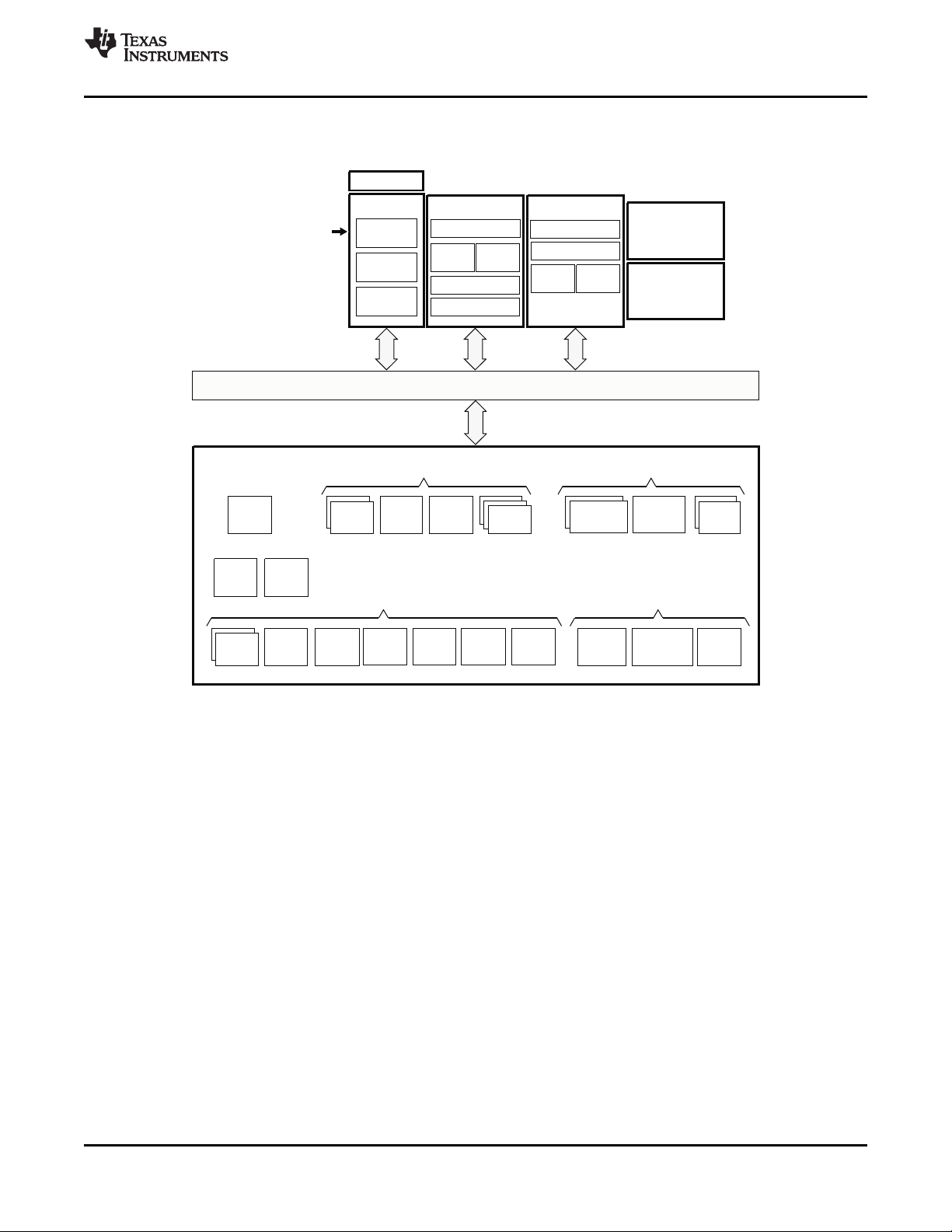
1.3 Functional Block Diagram
Figure 1-1 shows the functional block diagram of the device.
SPRS403G–DECEMBER 2007–REVISED OCTOBER 2010
Copyright © 2007–2010, Texas Instruments Incorporated Digital Media System-on-Chip (DMSoC) 5
Figure 1-1. TMS320DM6467 Functional Block Diagram
Submit Documentation Feedback
Product Folder Link(s): TMS320DM6467
Page 6
TMS320DM6467
SPRS403G–DECEMBER 2007–REVISED OCTOBER 2010
www.ti.com
1 Digital Media System-on-Chip (DMSoC) ............ 1 7.1 Parameter Information ............................ 143
1.1 Features .............................................. 1
1.2 Description ........................................... 3
1.3 Functional Block Diagram ............................ 5
2 Revision History ......................................... 7
3 Device Overview ........................................ 8
3.1 Device Characteristics ............................... 8
3.2 Device Compatibility ................................ 11
3.3 ARM Subsystem .................................... 11
3.4 DSP Subsystem .................................... 15
3.5 Memory Map Summary ............................. 20
3.6 Pin Assignments .................................... 24
3.7 Terminal Functions ................................. 30
3.8 Device Support ..................................... 81
3.9 Documentation Support ............................ 83
3.10 Community Resources ............................. 83
4 Device Configurations ................................ 85
4.1 System Module Registers .......................... 85
4.2 Power Considerations .............................. 87
4.3 Clock Considerations ............................... 90
4.4 Boot Sequence ..................................... 97
4.5 Configurations At Reset ........................... 103
4.6 Configurations After Reset ........................ 106
4.7 Multiplexed Pin Configurations .................... 114
4.8 Debugging Considerations ........................ 137
5 System Interconnect ................................ 139
6 Device Operating Conditions ...................... 140
6.1 Absolute Maximum Ratings Over Operating Case
Temperature Range (Unless Otherwise Noted)
..................................................... 140
6.2 Recommended Operating Conditions ............. 141
6.3 Electrical Characteristics Over Recommended
Ranges of Supply Voltage and Operating
Temperature (Unless Otherwise Noted) .......... 142
7 Peripheral Information and Electrical
Specifications ......................................... 143
7.2 Recommended Clock and Control Signal Transition
Behavior ........................................... 144
7.3 Power Supplies .................................... 145
7.4 External Clock Input From DEV_MXI/DEV_CLKIN
and AUX_MXI/AUX_CLKIN Pins .................. 154
7.5 Clock PLLs ........................................ 157
7.6 Enhanced Direct Memory Access (EDMA3)
Controller .......................................... 165
7.7 Reset .............................................. 185
7.8 Interrupts .......................................... 196
7.9 External Memory Interface (EMIF) ................ 202
7.10 DDR2 Memory Controller ......................... 209
7.11 Video Port Interface (VPIF) ....................... 222
7.12 Transport Stream Interface (TSIF) ................ 230
7.13 Clock Recovery Generator (CRGEN) ............. 240
7.14 Video Data Conversion Engine (VDCE) .......... 243
7.15 Peripheral Component Interconnect (PCI) ........ 246
7.16 Ethernet MAC (EMAC) ............................ 252
7.17 Management Data Input/Output (MDIO) .......... 262
7.18 Host-Port Interface (HPI) Peripheral .............. 264
7.19 USB 2.0 ........................................... 272
7.20 ATA Controller ..................................... 282
7.21 VLYNQ ............................................ 297
7.22 Multichannel Audio Serial Port (McASP0/1)
Peripherals ........................................ 302
7.23 Serial Peripheral Interface (SPI) .................. 314
7.24 Universal Asynchronouse Receiver/Transmitter
(UART) ............................................ 329
7.25 Inter-Integrated Circuit (I2C) ...................... 336
7.26 Pulse Width Modulator (PWM) .................... 340
7.27 Timers ............................................. 342
7.28 General-Purpose Input/Output (GPIO) ............ 345
7.29 IEEE 1149.1 JTAG ................................ 348
8 Mechanical Packaging and Orderable
Information ............................................ 351
8.1 Thermal Data for ZUT ............................. 351
8.2 Packaging Information ............................ 351
6 Contents Copyright © 2007–2010, Texas Instruments Incorporated
Submit Documentation Feedback
Product Folder Link(s): TMS320DM6467
Page 7

TMS320DM6467
www.ti.com
2 Revision History
This data manual revision history highlights the technical changes made to the SPRS403F device-specific
data manual to make it an SPRS403G revision.
Scope: Applicable updates to the DM646x DMSoC device family, specifically relating to the
TMS320DM6467 device (all Silicon Revisions 3.0, 1.1, and 1.0) which is now in the production data (PD)
stage of development have been incorporated.
• Added, for clarification, the device-specific DDR2 Memory Controller speeds: 297-MHz (-594) and
310.5-MHz (-729).
SEE ADDITIONS/MODIFICATIONS/DELETIONS
Global
Section 1.2
Description
Section 3.5 Table 3-3, Memory Map Summary:
Memory Map Summary
• Added, for clarification, the device-specific DDR2 Memory Controller speeds: 297-MHz (-594) and
310.5-MHz (-729)
• First paragraph:
– Updated/Changed "... to meet the networked media encode and decode application processing
needs ..." to "... to meet the networked media encode and decode digital media processing needs
..."
• Deleted C64x+ PCI Data access to address range 0x3000 0000 to 0x3FFF FFFF
Table 3-4, Configuration Memory Map Summary:
• Deleted C64x+ Timer2 access at address range 0x01C2 1C00 to 0x01C2 1FFF
• Deleted C64x+ PLL Controller1 access at address range 0x01C4 0800 to 0x01C4 0BFF
• Deleted C64x+ PLL Controller2 access at address range 0x01C4 0C00 to 0x01C4 0FFF
• Deleted HPI, PCI, and VLYNQ Master Peripheral Accessibility for address range 0x01D0 2000 to 0x01DF
FFFF
• Deleted HPI, PCI, and VLYNQ Master Peripheral Accessibility for address range 0x01E0 0000 to 0x01FF
FFFF
SPRS403G–DECEMBER 2007–REVISED OCTOBER 2010
Section 3.7 Table 3-6, Oscillator/PLL Terminal Functions:
Terminal Functions
Section 3.8.2 Figure 3-8, Device Nomenclature:
Device and
Development-Support Tool
Nomenclature
Section 6 Section 6.2, Recommended Operating Conditions:
Device Operating
Conditions
Section 7 Section 7.1.3, Timing Parameters and Board Routing Analysis:
Peripheral Information and
Electrical Specifications
• Updated/Changed DEV_CVDDdescription
• Updated/Changed AUX_CVDDdescription
Table 3-10, DDR2 Memory Controller Terminal Functions:
• Updated/Changed the ± resistor tolerance value to "5%" for the DDR_ZN [M19] and DDR_ZP [L19]
signals
• Updated figure
• Added associated "For actual device part numbers (P/Ns) and ordering information, ..." footnote
• Updated/Changed DDR_ZP tolerance from "±0.5%" to "±5%"
• Updated/ Changed DDR_ZN tolerance from "±0.5%" to "±5%"
• Updated/Changed second paragraph ("For the DDR2 memory controller interface, it is not ...")
Copyright © 2007–2010, Texas Instruments Incorporated Revision History 7
Submit Documentation Feedback
Product Folder Link(s): TMS320DM6467
Page 8

TMS320DM6467
SPRS403G–DECEMBER 2007–REVISED OCTOBER 2010
SEE ADDITIONS/MODIFICATIONS/DELETIONS
Section 7.4.1 Figure 7-8, 27-MHz System Oscillator:
Clock Input Option 1—Cr
ystal
Section 7.4.2 Figure 7-10, 1.8-V LVCMOS-Compatible Clock Input:
Clock Input Option
2—1.8-V
LVCMOS-Compatible Clock
Input
Section 7.10.1 Table 7-32, Switching Characteristics Over Recommended Operating Conditions for DDR2 Memory
DDR2 Memory Controller Controller:
Electrical Data/Timing
Section 7.15.3 Deleted PCI Configuration Register table (was Table 7-63)
PCI Peripheral Register
Description(s)
Section 7.17.2 Table 7-80, Timing Requirements for MDIO Input:
Management Data
Input/Output (MDIO)
Electrical Data/Timing
Section 7.29
IEEE 1149.1 JTAG
• Added associated "The DEV_CVDDcore voltage value is device dependent (e.g., ..." footnote for
clarification
Figure 7-9, 24-MHz Auxiliary Oscillator:
• Added associated "The AUX_CVDDcore voltage value is device dependent (e.g., ..." footnote for
clarification
• Added associated "The DEV_CVDDcore voltage value is device dependent (e.g., ..." footnote for
clarification
Figure 7-11, 1.8-V LVCMOS-Compatible Clock Input:
• Added associated "The AUX_CVDDcore voltage value is device dependent (e.g., ..." footnote for
clarification
• Added frequency parameter with MIN/MAX values for clarification
• Updated/Changed the MIN value for t
from "10" to "0" ns.
• Deleted "For maximum reliability," from the "... DM6467 includes an internal pulldown (IPD) on the TRST
pin ..." paragraph [Cleared Documentation Feedback Issue]
h(MDCLKH-MDIO)
, Hold time, MDIO data input valid after MDCLK high
www.ti.com
3 Device Overview
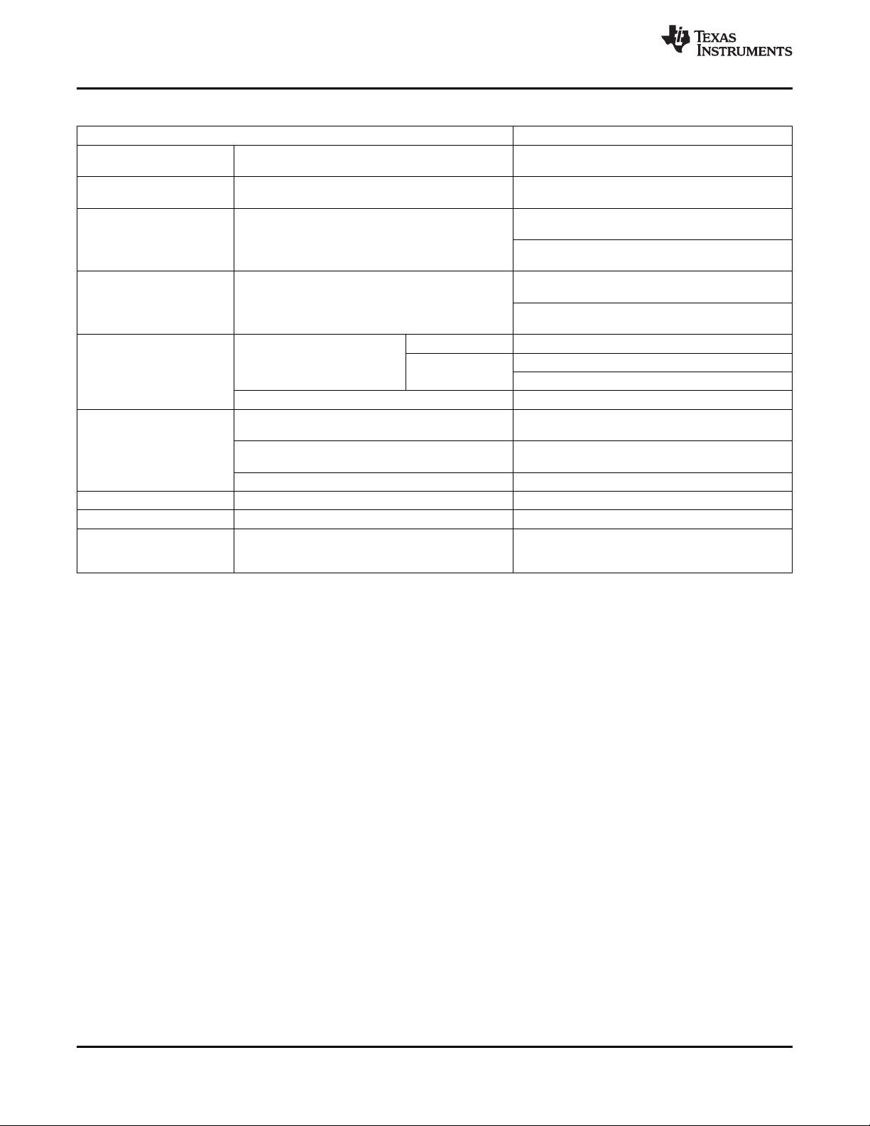
3.1 Device Characteristics
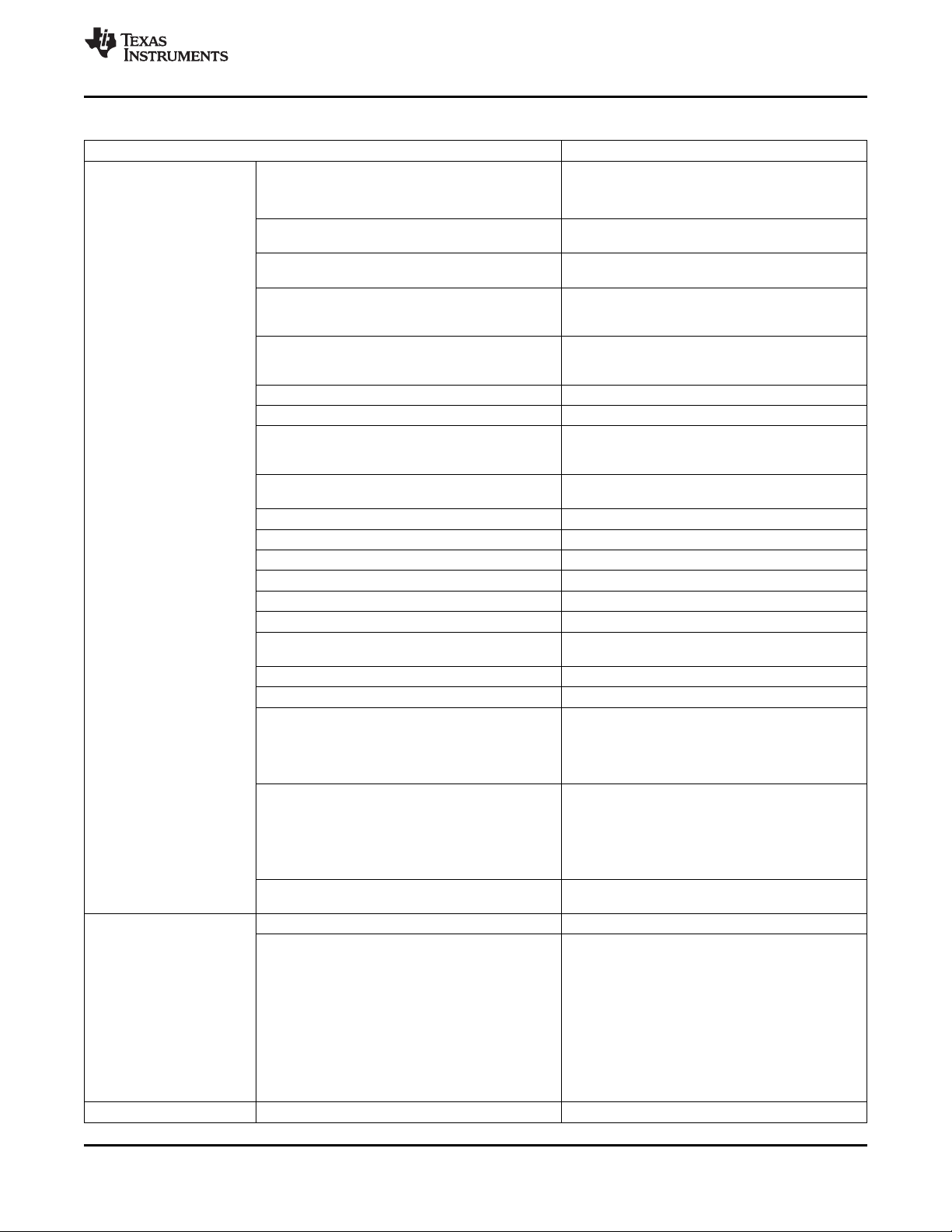
Table 3-1 provides an overview of the TMS320DM6467 SoC. The table shows significant features of the
device, including the capacity of on-chip RAM, peripherals, internal peripheral bus frequency relative to the
C64x+ DSP, and the package type with pin count.
8 Device Overview Copyright © 2007–2010, Texas Instruments Incorporated
Submit Documentation Feedback
Product Folder Link(s): TMS320DM6467
Page 9
TMS320DM6467
www.ti.com
SPRS403G–DECEMBER 2007–REVISED OCTOBER 2010
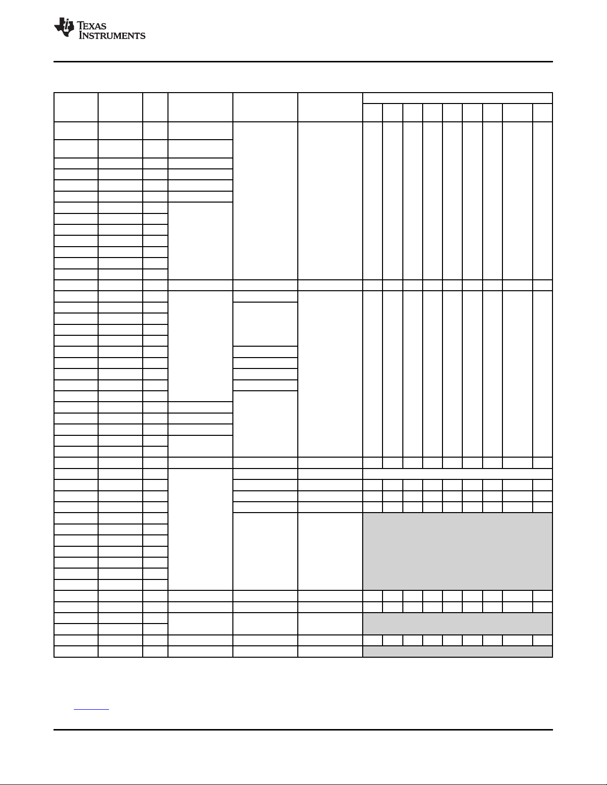
Table 3-1. Characteristics of the DM6467 Processor
HARDWARE FEATURES DM6467
DDR2 Memory Controller
297-MHz (-594)
310.5-MHz (-729)
Asynchronous EMIF (EMIFA)
EDMA
Timers separate 32-bit timers)
UART control)
SPI 1 (supports 2 slave devices)
I2C 1 (Master/Slave)
Multichannel Audio Serial Port (McASP) one DIT transmit only with 1 serializer for S/PDIF
Peripherals
Not all peripherals pins are
available at the same time
(for more detail, see the
Device Configurations
section).
On-Chip Memory
CPU ID + CPU Rev ID Control Status Register (CSR.[31:16]) 0x1000
10/100/1000 Ethernet MAC with Management Data
Input/Output (MDIO)
VLYNQ 1
General-Purpose Input/Output Port (GPIO) Up to 33 pins
PWM 2 outputs
ATA 1 (ATA/ATAPI-6)
PCI 1 (32-bit, 33 MHz)
HPI 1 (16-/32-bit multiplexed address/data)
VDCE
Clock Recovery Generator (CRGEN) 1
Power Sleep Controller (PSC) 1 (peripheral/module clock gating)
Configurable Video Port Interface (VPIF) 1 16-bit Y/C capture channel or
99-MHz (-594) 1 8-/10-/12-bit raw video capture channel and
108-MHz (-729) 2 8-bit BT.656 display channels or
Transport Stream Interface (TSIF) 1 with serial-only input and output
USB 2.0
Size (Bytes) 248KB RAM, 8KB ROM
Organization
Asynchronous (8/16-bit bus width) RAM, Flash
2 64-Bit General Purpose (each configurable as 2
3 (with SIR, MIR, CIR support and RTS/CTS flow
1 with 8-bit parallel or serial input and output
Each with corresponding clock recovery generator
DSP
• 32KB L1 Program (L1P)/Cache (up to 32KB)
• 32KB L1 Data (L1D)/Cache (up to 32KB)
• 128KB Unified Mapped RAM/Cache (L2)
ARM
• 16KB I-cache
• 8KB D-cache
• 32KB RAM
• 8KB ROM
DDR2 (16/32-bit bus width)
(NOR, NAND)
64 independent channels
8 QDMA channels
1 64-Bit Watchdog
(UART0 Supports Modem Interface)
2 (one transmit/receive with 4 serializers,
output)
1 (with MII/GMII Interface)
1 [horizontal and vertical downscaling,
chroma conversion (4:2:2↔4:2:0)]
2 8-bit BT.656 capture channels or
1 16-bit Y/C display channel
MPEG transport stream interface
(CRGEN) for external VCXO control.
High- and Full-Speed Device
High-, Full-, and Low-Speed Host
Copyright © 2007–2010, Texas Instruments Incorporated Device Overview 9
Submit Documentation Feedback
Product Folder Link(s): TMS320DM6467
Page 10
TMS320DM6467
SPRS403G–DECEMBER 2007–REVISED OCTOBER 2010
www.ti.com
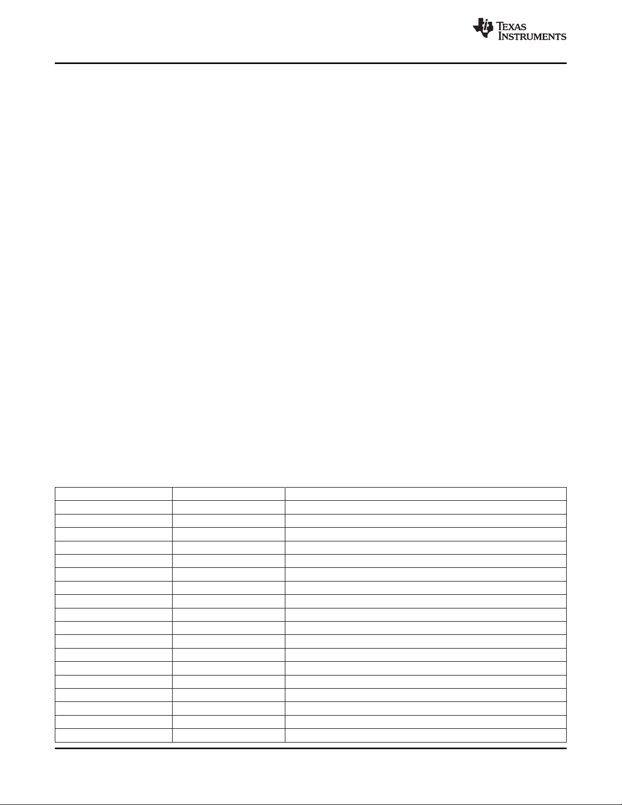
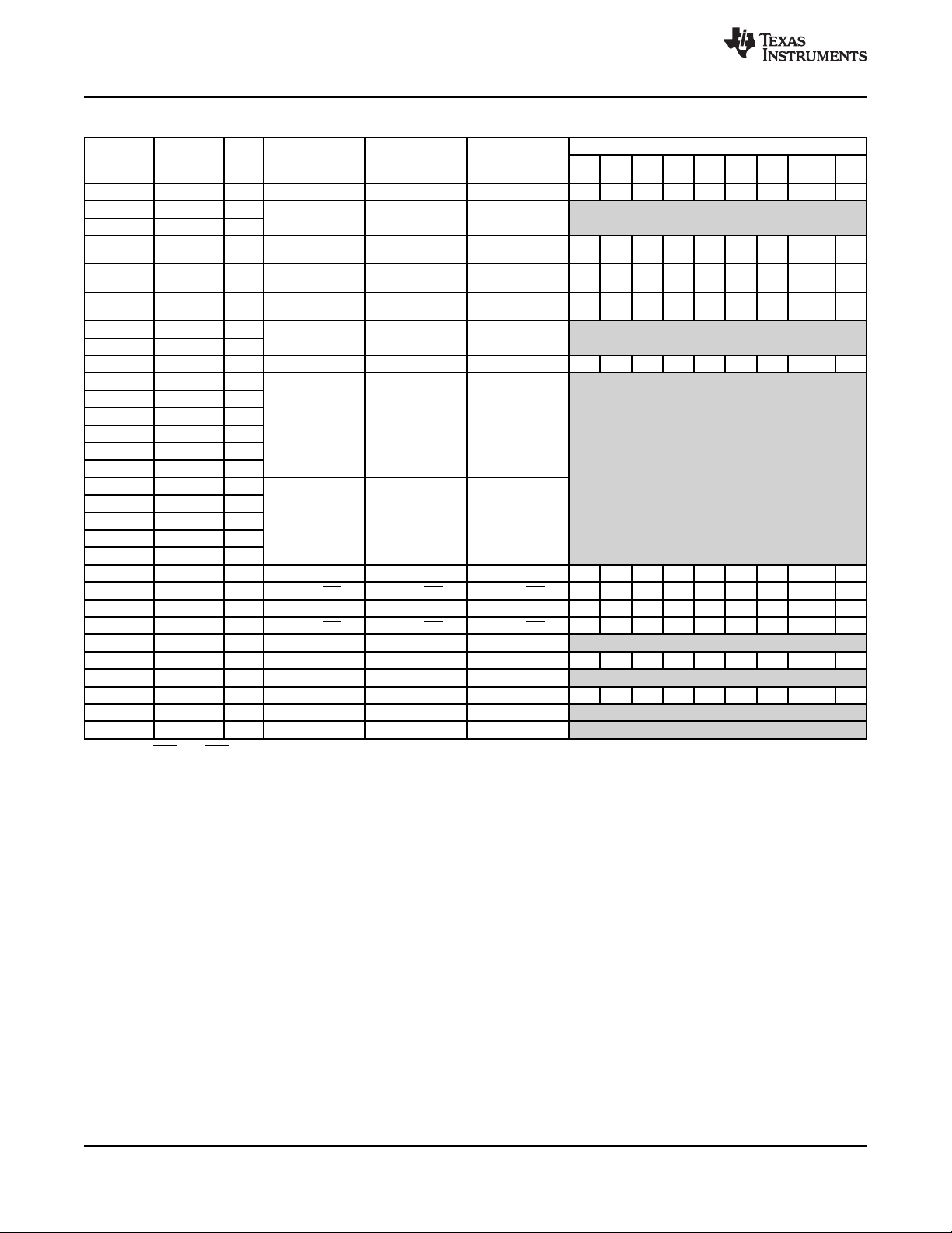
Table 3-1. Characteristics of the DM6467 Processor (continued)
HARDWARE FEATURES DM6467
C64x+ Megamodule Revision ID Register (MM_REVID[15:0])
Revision (address location: 0x0181 2000)
JTAG BSDL_ID
CPU Frequency MHz
Cycle Time ns
Voltage Core (V) 1.2 V (-594V, -594AV)
PLL Options DEV_CLKIN frequency multiplier (PLLC2) x1 (Bypass), x14 to x22 (-594)
BGA Package 19 x 19 mm 529-Pin BGA (ZUT)
Process Technology mm 0.09 mm
Product Status
(1) PRODUCTION DATA information is current as of publication date. Products conform to specifications per the terms of the Texas
Instruments standard warranty. Production processing does not necessarily include testing of all parameters.
(1)
JTAGID Register See Section 7.29.1, JTAG ID (JTAGID) Register
(address location: 0x01C4 0028) Description(s)
ARM926 297 MHz(-594)
ARM926 364.5 MHz(-729)
Normal 1.2 V (-594, -594A, -729, -729D)
SmartReflex
(see Table 4-39)
I/O (V) 1.8 V, 3.3 V (-594, -729)
DEV_CLKIN frequency multiplier (PLLC1) x1 (Bypass), x14 to x22 (-594)
(27-MHz reference) x1 (Bypass), x14 to x27 (-729)
(27-MHz reference) x1 (Bypass), x14 to x23 (-729)
AUX_CLKIN frequency 24/48-MHz reference
Product Preview (PP),
Advance Information (AI), PD
or Production Data (PD)
0x0000
DSP 594 MHz (-594)
DSP 729 MHz (-729)
DSP 1.68 ns (-594)
DSP 1.37 ns (-729)
ARM926 3.37 ns (-594)
ARM926 2.74 ns (-729)
1.05 V (-594V, -594AV)
10 Device Overview Copyright © 2007–2010, Texas Instruments Incorporated
Submit Documentation Feedback
Product Folder Link(s): TMS320DM6467
Page 11

TMS320DM6467
www.ti.com
3.2 Device Compatibility
The ARM926EJ-S RISC CPU is compatible with other ARM9 CPUs from ARM Holdings plc.
The C64x+ DSP core is code-compatible with the C6000™ DSP platform and supports features of the
C64x DSP family.
3.3 ARM Subsystem
The ARM Subsystem is designed to give the ARM926EJ-S (ARM9) master control of the device. In
general, the ARM is responsible for configuration and control of the device; including the DSP Subsystem,
the VPSS Subsystem, and a majority of the peripherals and external memories.
The ARM Subsystem includes the following features:
• ARM926EJ-S RISC processor
• ARMv5TEJ (32/16-bit) instruction set
• Little endian operation
• Co-Processor 15 (CP15)
• MMU
• 16KB Instruction cache
• 8KB Data cache
• Write Buffer
• 32KB Internal Tightly-Coupled Memory (TCM) RAM (32-bit wide access)
• 8KB Internal ROM (ARM bootloader for non-EMIFA boot options)
• Embedded Trace Module and Embedded Trace Buffer (ETM/ETB)
• ARM Interrupt Controller
• PLL Controller
• Power and Sleep Controller (PSC)
• System Module
SPRS403G–DECEMBER 2007–REVISED OCTOBER 2010
3.3.1 ARM926EJ-S RISC CPU
The ARM Subsystem integrates the ARM926EJ-S processor. The ARM926EJ-S processor is a member of
ARM9 family of general-purpose microprocessors. This processor is targeted at multi-tasking applications
where full memory management, high performance, low die size, and low power are all important. The
ARM926EJ-S processor supports the 32-bit ARM and 16 bit THUMB instruction sets, enabling the user to
trade off between high performance and high code density. Specifically, the ARM926EJ-S processor
supports the ARMv5TEJ instruction set, which includes features for efficient execution of Java byte codes,
providing Java performance similar to Just in Time (JIT) Java interpreter, but without associated code
overhead.
The ARM926EJ-S processor supports the ARM debug architecture and includes logic to assist in both
hardware and software debug. The ARM926EJ-S processor has a Harvard architecture and provides a
complete high performance subsystem, including:
• ARM926EJ -S integer core
• CP15 system control coprocessor
• Memory Management Unit (MMU)
• Separate instruction and data Caches
• Write buffer
• Separate instruction and data Tightly-Coupled Memories (TCMs) [internal RAM] interfaces
• Separate instruction and data AHB bus interfaces
• Embedded Trace Module and Embedded Trace Buffer (ETM/ETB)
Copyright © 2007–2010, Texas Instruments Incorporated Device Overview 11
Submit Documentation Feedback
Product Folder Link(s): TMS320DM6467
Page 12

TMS320DM6467
SPRS403G–DECEMBER 2007–REVISED OCTOBER 2010
For more complete details on the ARM9, refer to the ARM926EJ-S Technical Reference Manual, available
at http://www.arm.com
3.3.2 CP15
The ARM926EJ-S system control coprocessor (CP15) is used to configure and control instruction and
data caches, Tightly-Coupled Memories (TCMs), Memory Management Unit (MMU), and other ARM
subsystem functions. The CP15 registers are programmed using the MRC and MCR ARM instructions,
when the ARM in a privileged mode such as supervisor or system mode.
3.3.3 MMU
The ARM926EJ-S MMU provides virtual memory features required by operating systems such as Linux®,
Windows® CE, Ultron®, ThreadX®, etc. A single set of two level page tables stored in main memory is
used to control the address translation, permission checks and memory region attributes for both data and
instruction accesses. The MMU uses a single unified Translation Lookaside Buffer (TLB) to cache the
information held in the page tables. The MMU features are:
• Standard ARM architecture v4 and v5 MMU mapping sizes, domains and access protection scheme.
• Mapping sizes are:
– 1MB (sections)
– 64KB (large pages)
– 4KB (small pages)
– 1KB (tiny pages)
• Access permissions for large pages and small pages can be specified separately for each quarter of
the page (subpage permissions)
• Hardware page table walks
• Invalidate entire TLB, using CP15 register 8
• Invalidate TLB entry, selected by MVA, using CP15 register 8
• Lockdown of TLB entries, using CP15 register 10
www.ti.com
3.3.4 Caches and Write Buffer
The size of the Instruction Cache is 16KB, Data cache is 8KB. Additionally, the Caches have the following
features:
• Virtual index, virtual tag, and addressed using the Modified Virtual Address (MVA)
• Four-way set associative, with a cache line length of eight words per line (32-bytes per line) and with
two dirty bits in the Dcache
• Dcache supports write-through and write-back (or copy back) cache operation, selected by memory
region using the C and B bits in the MMU translation tables.
• Critical-word first cache refilling
• Cache lockdown registers enable control over which cache ways are used for allocation on a line fill,
providing a mechanism for both lockdown, and controlling cache corruption
• Dcache stores the Physical Address TAG (PA TAG) corresponding to each Dcache entry in the TAG
RAM for use during the cache line write-backs, in addition to the Virtual Address TAG stored in the
TAG RAM. This means that the MMU is not involved in Dcache write-back operations, removing the
possibility of TLB misses related to the write-back address.
• Cache maintenance operations provide efficient invalidation of, the entire Dcache or Icache, regions of
the Dcache or Icache, and regions of virtual memory.
The write buffer is used for all writes to a noncachable bufferable region, write-through region and write
misses to a write-back region. A separate buffer is incorporated in the Dcache for holding write-back for
cache line evictions or cleaning of dirty cache lines. The main write buffer has 16-word data buffer and a
four-address buffer. The Dcache write-back has eight data word entries and a single address entry.
12 Device Overview Copyright © 2007–2010, Texas Instruments Incorporated
Submit Documentation Feedback
Product Folder Link(s): TMS320DM6467
Page 13

TMS320DM6467
www.ti.com
3.3.5 Tightly Coupled Memory (TCM)
ARM internal RAM is provided for storing real-time and performance-critical code/data and the Interrupt
Vector table. ARM internal ROM enables non-EMIFA boot options, such as NAND and UART. The RAM
and ROM memories interfaced to the ARM926EJ-S via the tightly coupled memory interface that provides
for separate instruction and data bus connections. Since the ARM TCM does not allow instructions on the
D-TCM bus or data on the I-TCM bus, an arbiter is included so that both data and instructions can be
stored in the internal RAM/ROM. The arbiter also allows accesses to the RAM/ROM from extra-ARM
sources (e.g., EDMA or other masters). The ARM926EJ-S has built-in DMA support for direct accesses to
the ARM internal memory from a non-ARM master. Because of the time-critical nature of the TCM link to
the ARM internal memory, all accesses from non-ARM devices are treated as DMA transfers.
Instruction and Data accesses are differentiated via accessing different memory map regions, with the
instruction region from 0x0000 through 0x7FFF and data from 0x10000 through 0x17FFF. The instruction
region at 0x0000 and data region at 0x10000 map to the same physical 32-KB TCM RAM. Placing the
instruction region at 0x0000 is necessary to allow the ARM Interrupt Vector table to be placed at 0x0000,
as required by the ARM architecture. The internal 32-KB RAM is split into two physical banks of 16KB
each, which allows simultaneous instruction and data accesses to be accomplished if the code and data
are in separate banks.
3.3.6 Advanced High-Performance Bus (AHB)
The ARM Subsystem uses the AHB port of the ARM926EJ-S to connect the ARM to the Config bus and
the external memories. Arbiters are employed to arbitrate access to the separate D-AHB and I-AHB by the
Config Bus and the external memories bus.
SPRS403G–DECEMBER 2007–REVISED OCTOBER 2010
3.3.7 Embedded Trace Macrocell (ETM) and Embedded Trace Buffer (ETB)
To support real-time trace, the ARM926EJ-S processor provides an interface to enable connection of an
Embedded Trace Macrocell (ETM). The ARM926ES-J Subsystem in the DM6467 also includes the
Embedded Trace Buffer (ETB). The ETM consists of two parts:
• Trace Port provides real-time trace capability for the ARM9.
• Triggering facilities provide trigger resources, which include address and data comparators, counter,
and sequencers.
The DM6467 trace port is not pinned out and is instead only connected to the Embedded Trace Buffer.
The ETB has a 4KB buffer memory. ETB enabled debug tools are required to read/interpret the captured
trace data.
3.3.8 ARM Memory Mapping
The ARM memory map is shown in Section 3.5, Memory Map Summary of this document. The ARM has
access to memories shown in the following sections.
3.3.8.1 ARM Internal Memories
The ARM has access to the following ARM internal memories:
• 32KB ARM Internal RAM on TCM interface, logically separated into two 16KB pages to allow
simultaneous access on any given cycle if there are separate accesses for code (I-TCM bus) and data
(D-TCM) to the different memory regions.
• 8KB ARM Internal ROM
3.3.8.2 External Memories
The ARM has access to the following external memories:
• DDR2 Synchronous DRAM
• Asynchronous EMIF / NOR Flash / NAND Flash
• ATA
Copyright © 2007–2010, Texas Instruments Incorporated Device Overview 13
Submit Documentation Feedback
Product Folder Link(s): TMS320DM6467
Page 14

TMS320DM6467
SPRS403G–DECEMBER 2007–REVISED OCTOBER 2010
3.3.8.3 DSP Memories
The ARM has access to the following DSP memories:
• L2 RAM
• L1P RAM
• L1D RAM
3.3.8.4 ARM-DSP Integration
DM6467 ARM and DSP integration features are as follows:
• DSP visibility from ARM’s memory map, see Section 3.5, Memory Map Summary, for details
• Boot Modes for DSP - see Device Configurations section, Section 4.4.1, DSP Boot, for details
• ARM control of DSP boot / reset - see Device Configurations section, Section 4.4.2.4, ARM Boot, for
details
• ARM control of DSP isolation and powerdown / powerup - see Section 4, Device Configurations, for
details
• ARM & DSP Interrupts - see Section 7.8.1, ARM CPU Interrupts, and Section 7.8.2, DSP Interrupts, for
details
3.3.9 Peripherals
The ARM9 has access to all of the peripherals on the DM6467 device.
www.ti.com
3.3.10 PLL Controller (PLLC)
The ARM Subsystem includes the PLL Controller. The PLL Controller contains a set of registers for
configuring DM6467’s two internal PLLs (PLL1 and PLL2). The PLL Controller provides the following
configuration and control:
• PLL Bypass Mode
• Set PLL multiplier parameters
• Set PLL divider parameters
• PLL power down
• Oscillator power down
The PLLs are briefly described in this document in the Clocking section. For more detailed information on
the PLLs and PLL Controller register descriptions, see the TMS320DM646x DMSoC ARM Subsystem
Reference Guide (literature number SPRUEP9).
3.3.11 Power and Sleep Controller (PSC)
The ARM Subsystem includes the Power and Sleep Controller (PSC). Through register settings
accessible by the ARM9, the PSC provides two levels of power savings: peripheral/module clock gating
and power domain shut-off. Brief details on the PSC are given in Section 7.3, Power Supplies. For more
detailed information and complete register descriptions for the PSC, see the TMS320DM646x DMSoC
ARM Subsystem Reference Guide (literature number SPRUEP9).
3.3.12 ARM Interrupt Controller (AINTC)
The ARM Interrupt Controller (AINTC) accepts device interrupts and maps them to either the ARM’s IRQ
(interrupt request) or FIQ (fast interrupt request). The ARM Interrupt Controller is briefly described in this
document in the Interrupts section. For detailed information on the ARM Interrupt Controller, see the
TMS320DM646x DMSoC ARM Subsystem Reference Guide (literature number SPRUEP9).
14 Device Overview Copyright © 2007–2010, Texas Instruments Incorporated
Submit Documentation Feedback
Product Folder Link(s): TMS320DM6467
Page 15

TMS320DM6467
www.ti.com
3.3.13 System Module
The ARM Subsystem includes the System module. The System module consists of a set of registers for
configuring and controlling a variety of system functions. For details and register descriptions for the
System module, see Section 4, Device Configurations and see the TMS320DM646x DMSoC ARM
Subsystem Reference Guide (literature number SPRUEP9).
3.3.14 Power Management
DM6467 has several means of managing power consumption. There is extensive use of clock gating,
which reduces the power used by global device clocks and individual peripheral clocks. Clock
management can be utilized to reduce clock frequencies in order to reduce switching power. For more
details on power management techniques, see Section 4, Device Configurations, Section 7, Peripheral
and Electrical Specifications, and see the TMS320DM646x DMSoC ARM Subsystem Reference Guide
(literature number SPRUEP9).
DM6467 gives the programmer full flexibility to use any and all of the previously mentioned capabilities to
customize an optimal power management strategy. Several typical power management scenarios are
described in the following sections.
3.4 DSP Subsystem
The DSP Subsystem includes the following features:
• C64x+ DSP CPU
• 32KB L1 Program (L1P)/Cache (up to 32KB)
• 32KB L1 Data (L1D)/Cache (up to 32KB)
• 128KB Unified Mapped RAM/Cache (L2)
• Little endian
SPRS403G–DECEMBER 2007–REVISED OCTOBER 2010
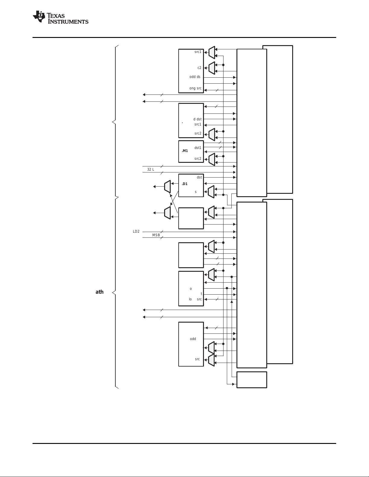
3.4.1 C64x+ DSP CPU Description
The C64x+ Central Processing Unit (CPU) consists of eight functional units, two register files, and two
data paths as shown in Figure 3-1. The two general-purpose register files (A and B) each contain
32 32-bit registers for a total of 64 registers. The general-purpose registers can be used for data or can be
data address pointers. The data types supported include packed 8-bit data, packed 16-bit data, 32-bit
data, 40-bit data, and 64-bit data. Values larger than 32 bits, such as 40-bit-long or 64-bit-long values are
stored in register pairs, with the 32 LSBs of data placed in an even register and the remaining 8 or
32 MSBs in the next upper register (which is always an odd-numbered register).
The eight functional units (.M1, .L1, .D1, .S1, .M2, .L2, .D2, and .S2) are each capable of executing one
instruction every clock cycle. The .M functional units perform all multiply operations. The .S and .L units
perform a general set of arithmetic, logical, and branch functions. The .D units primarily load data from
memory to the register file and store results from the register file into memory.
The C64x+ CPU extends the performance of the C64x core through enhancements and new features.
Each C64x+ .M unit can perform one of the following each clock cycle: one 32 x 32 bit multiply, one 16 x
32 bit multiply, two 16 x 16 bit multiplies, two 16 x 32 bit multiplies, two 16 x 16 bit multiplies with
add/subtract capabilities, four 8 x 8 bit multiplies, four 8 x 8 bit multiplies with add operations, and four
16 x 16 multiplies with add/subtract capabilities (including a complex multiply). There is also support for
Galois field multiplication for 8-bit and 32-bit data. Many communications algorithms such as FFTs and
modems require complex multiplication. The complex multiply (CMPY) instruction takes for 16-bit inputs
and produces a 32-bit real and a 32-bit imaginary output. There are also complex multiplies with rounding
capability that produces one 32-bit packed output that contain 16-bit real and 16-bit imaginary values. The
32 x 32 bit multiply instructions provide the extended precision necessary for audio and other
high-precision algorithms on a variety of signed and unsigned 32-bit data types.
Copyright © 2007–2010, Texas Instruments Incorporated Device Overview 15
Submit Documentation Feedback
Product Folder Link(s): TMS320DM6467
Page 16

TMS320DM6467
SPRS403G–DECEMBER 2007–REVISED OCTOBER 2010
The .L or (Arithmetic Logic Unit) now incorporates the ability to do parallel add/subtract operations on a
pair of common inputs. Versions of this instruction exist to work on 32-bit data or on pairs of 16-bit data
performing dual 16-bit add and subtracts in parallel. There are also saturated forms of these instructions.
The C64x+ core enhances the .S unit in several ways. In the C64x core, dual 16-bit MIN2 and MAX2
comparisons were only available on the .L units. On the C64x+ core they are also available on the .S unit
which increases the performance of algorithms that do searching and sorting. Finally, to increase data
packing and unpacking throughput, the .S unit allows sustained high performance for the quad 8-bit/16-bit
and dual 16-bit instructions. Unpack instructions prepare 8-bit data for parallel 16-bit operations. Pack
instructions return parallel results to output precision including saturation support.
Other new features include:
• SPLOOP - A small instruction buffer in the CPU that aids in creation of software pipelining loops where
multiple iterations of a loop are executed in parallel. The SPLOOP buffer reduces the code size
associated with software pipelining. Furthermore, loops in the SPLOOP buffer are fully interruptible.
• Compact Instructions - The native instruction size for the C6000 devices is 32 bits. Many common
instructions such as MPY, AND, OR, ADD, and SUB can be expressed as 16 bits if the C64x+
compiler can restrict the code to use certain registers in the register file. This compression is
performed by the code generation tools.
• Instruction Set Enhancement - As noted above, there are new instructions such as 32-bit
multiplications, complex multiplications, packing, sorting, bit manipulation, and 32-bit Galois field
multiplication.
• Exceptions Handling - Intended to aid the programmer in isolating bugs. The C64x+ CPU is able to
detect and respond to exceptions, both from internally detected sources (such as illegal op-codes) and
from system events (such as a watchdog time expiration).
• Privilege - Defines user and supervisor modes of operation, allowing the operating system to give a
basic level of protection to sensitive resources. Local memory is divided into multiple pages, each with
read, write, and execute permissions.
• Time-Stamp Counter - Primarily targeted for Real-Time Operating System (RTOS) robustness, a
free-running time-stamp counter is implemented in the CPU which is not sensitive to system stalls.
www.ti.com
For more details on the C64x+ CPU and its enhancements over the C64x architecture, see the following
documents:
• TMS320C64x/C64x+ DSP CPU and Instruction Set Reference Guide (literature number SPRU732)
• TMS320C64x Technical Overview (literature number SPRU395)
16 Device Overview Copyright © 2007–2010, Texas Instruments Incorporated
Submit Documentation Feedback
Product Folder Link(s): TMS320DM6467
Page 17
src2
src2
.D1
.M1
.S1
.L1
long src
odd dst
src2
src1
src1
src1
src1
even dst
even dst
odd dst
dst1
dst
src2
src2
src2
long src
DA1
ST1b
LD1b
LD1a
ST1a
Data path A
Odd
register
file A
(A1, A3,
A5...A31)
Odd
register
file B
(B1, B3,
B5...B31)
.D2
src1
dst
src2
DA2
LD2a
LD2b
src2
.M2
src1
dst1
.S2
src1
even dst
long src
odd dst
ST2a
ST2b
long src
.L2
even dst
odd dst
src1
Data path B
Control Register
32 MSB
32 LSB
dst2
(A)
32 MSB
32 LSB
2x
1x
32 LSB
32 MSB
32 LSB
32 MSB
dst2
(B)
(B)
(A)
8
8
8
8
32
32
32
32
(C)
(C)
Even
register
file A
(A0, A2,
A4...A30)
Even
register
file B
(B0, B2,
B4...B30)
(D)
(D)
(D)
(D)
A. On .M unit, dst2 is 32 MSB.
B. On .M unit, dst1 is 32 LSB.
C. On C64x CPU .M unit, src2 is 32 bits; on C64x+ CPU .M unit, src2 is 64 bits.
D. On .L and .S units, odd dst connects to odd register files and even dst connects to even register files.
TMS320DM6467
www.ti.com
SPRS403G–DECEMBER 2007–REVISED OCTOBER 2010
Figure 3-1. TMS320C64x+™ CPU (DSP Core) Data Paths
Copyright © 2007–2010, Texas Instruments Incorporated Device Overview 17
Submit Documentation Feedback
Product Folder Link(s): TMS320DM6467
Page 18
TMS320DM6467
SPRS403G–DECEMBER 2007–REVISED OCTOBER 2010
3.4.2 DSP Memory Mapping
The DSP memory map is shown in Section 3.5, Memory Map Summary. Configuration of the control
registers for DDR2, EMIFA, and ARM Internal RAM is supported by the ARM. The DSP has access to
memories shown in the following sections.
3.4.2.1 ARM Internal Memories
The DSP has access to the 32KB ARM Internal RAM on the ARM D-TCM interface (i.e., data only).
3.4.2.2 External Memories
The DSP has access to the following External memories:
• DDR2 Synchronous DRAM
• Asynchronous EMIF / NOR Flash
• ATA
3.4.2.3 DSP Internal Memories
The DSP has access to the following DSP memories:
• L2 RAM
• L1P RAM
• L1D RAM
www.ti.com
3.4.2.4 C64x+ CPU
The C64x+ core uses a two-level cache-based architecture. The Level 1 Program memory/cache (L1P)
consists of 32 KB memory space that can be configured as mapped memory or direct mapped cache. The
Level 1 Data memory/cache (L1D) consists of 32 KB that can be configured as mapped memory or 2-way
set associated cache. The Level 2 memory/cache (L2) consists of a 128 KB RAM memory space that is
shared between program and data space. L2 memory can be configured as mapped memory, cache, or a
combination of both.
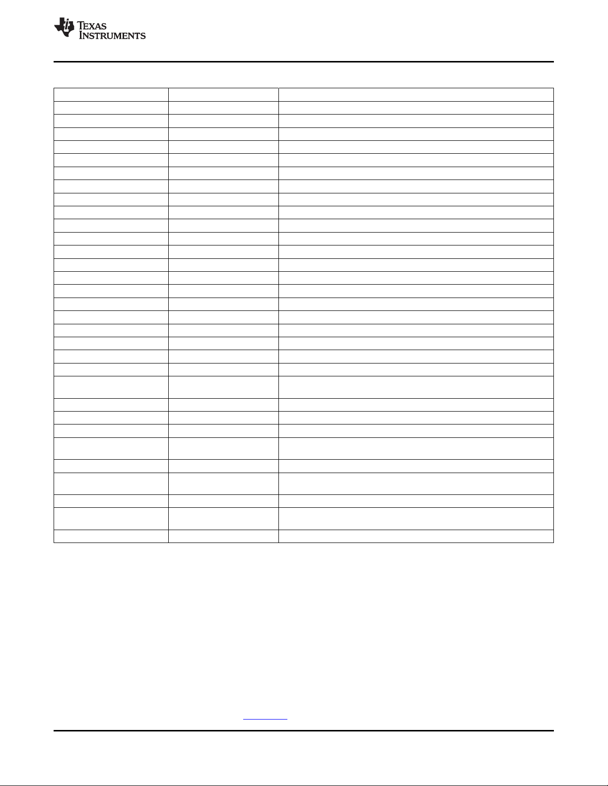
Table 3-2 shows a memory map of the C64x+ CPU cache registers for the device.
Table 3-2. C64x+ Cache Registers
HEX ADDRESS RANGE REGISTER ACRONYM DESCRIPTION
0x0184 0000 L2CFG L2 Cache configuration register
0x0184 0020 L1PCFG L1P Size Cache configuration register
0x0184 0024 L1PCC L1P Freeze Mode Cache configuration register
0x0184 0040 L1DCFG L1D Size Cache configuration register
0x0184 0044 L1DCC L1D Freeze Mode Cache configuration register
0x0184 0048 - 0x0184 0FFC - Reserved
0x0184 1000 EDMAWEIGHT L2 EDMA access control register
0x0184 1004 - 0x0184 1FFC - Reserved
0x0184 2000 L2ALLOC0 L2 allocation register 0
0x0184 2004 L2ALLOC1 L2 allocation register 1
0x0184 2008 L2ALLOC2 L2 allocation register 2
0x0184 200C L2ALLOC3 L2 allocation register 3
0x0184 2010 - 0x0184 3FFF - Reserved
0x0184 4000 L2WBAR L2 writeback base address register
0x0184 4004 L2WWC L2 writeback word count register
0x0184 4010 L2WIBAR L2 writeback invalidate base address register
0x0184 4014 L2WIWC L2 writeback invalidate word count register
0x0184 4018 L2IBAR L2 invalidate base address register
18 Device Overview Copyright © 2007–2010, Texas Instruments Incorporated
Submit Documentation Feedback
Product Folder Link(s): TMS320DM6467
Page 19
TMS320DM6467
www.ti.com
SPRS403G–DECEMBER 2007–REVISED OCTOBER 2010
Table 3-2. C64x+ Cache Registers (continued)
HEX ADDRESS RANGE REGISTER ACRONYM DESCRIPTION
0x0184 401C L2IWC L2 invalidate word count register
0x0184 4020 L1PIBAR L1P invalidate base address register
0x0184 4024 L1PIWC L1P invalidate word count register
0x0184 4030 L1DWIBAR L1D writeback invalidate base address register
0x0184 4034 L1DWIWC L1D writeback invalidate word count register
0x0184 4038 - Reserved
0x0184 4040 L1DWBAR L1D Block Writeback
0x0184 4044 L1DWWC L1D Block Writeback
0x0184 4048 L1DIBAR L1D invalidate base address register
0x0184 404C L1DIWC L1D invalidate word count register
0x0184 4050 - 0x0184 4FFF - Reserved
0x0184 5000 L2WB L2 writeback all register
0x0184 5004 L2WBINV L2 writeback invalidate all register
0x0184 5008 L2INV L2 Global Invalidate without writeback
0x0184 500C - 0x0184 5027 - Reserved
0x0184 5028 L1PINV L1P Global Invalidate
0x0184 502C - 0x0184 5039 - Reserved
0x0184 5040 L1DWB L1D Global Writeback
0x0184 5044 L1DWBINV L1D Global Writeback with Invalidate
0x0184 5048 L1DINV L1D Global Invalidate without writeback
0x0184 8000 - 0x0184 803C MAR0 - MAR15 Reserved (corresponds to byte address 0x0000 0000 - 0x0FFF FFFF)
0x0184 8040 MAR16
0x0184 8044 - 0x0184 80FC MAR17 - MAR63 Reserved (corresponds to byte address 0x1100 0000 - 0x3FFF FFFF)
0x0184 8100 MAR64 Reserved (corresponds to byte address 0x4000 0000 - 0x40FF FFFF)
0x0184 8104 MAR65 Reserved (corresponds to byte address 0x4100 0000 - 0x41FF FFFF)
0x0184 8108 - 0x0184 8124 MAR66 - MAR73
0x0184 8128 - 0x0184 812C MAR74 - MAR75 Reserved (corresponds to byte address 0x4A00 0000 - 0x4BFF FFFF)
0x0184 8130 - 0x0184 813C MAR76 - MAR79
0x0184 8140 - 0x0184 81FC MAR80 - MAR127 Reserved (corresponds to byte address 0x5000 0000 - 0x7FFF FFFF)
0x0184 8200 - 0x0184 82FC MAR128 - MAR191
0x0184 8300 - 0x0184 83FC MAR192 - MAR255 Reserved (corresponds to byte address 0xC000 0000 - 0xFFFF FFFF)
Memory Attribute Registers for ARM TCM (corresponds to byte address
0x1000 0000 - 0x10FF FFFF)
Memory Attribute Registers for EMIFA (corresponds to byte address 0x4200
0000 - 0x49FF FFFF)
Memory Attribute Registers for VLYNQ (corresponds to byte address
0x4C00 0000 - 0x4FFF FFFF)
Memory Attribute Registers for DDR2 (corresponds to byte address 0x8000
0000 - 0xBFFF FFFF)
3.4.3 Peripherals
The DSP has access/controllability of the following peripherals:
• HDVICP0/1
• EDMA
• McASP0/1
• 2 Timers (Timer0 and Timer1) that can each be configured as 1 64-bit or 2 32-bit timers
3.4.4 DSP Interrupt Controller
The DSP Interrupt Controller accepts device interrupts and appropriately maps them to the DSP’s
available interrupts. The DSP Interrupt Controller is briefly described in this document in the Interrupts
section. For more detailed on the DSP Interrupt Controller, see the TMS320C64x+ DSP Megamodule
Reference Guide (literature number SPRU871).
Copyright © 2007–2010, Texas Instruments Incorporated Device Overview 19
Submit Documentation Feedback
Product Folder Link(s): TMS320DM6467
Page 20

TMS320DM6467
SPRS403G–DECEMBER 2007–REVISED OCTOBER 2010
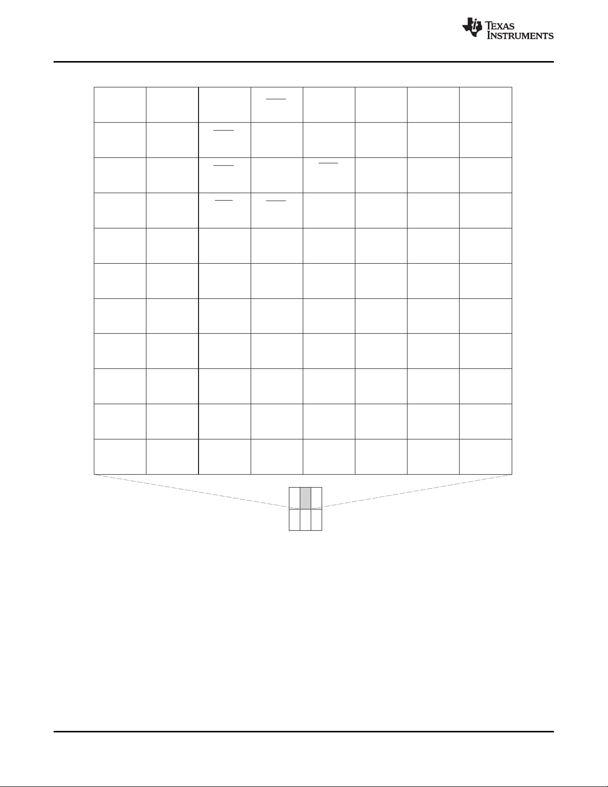
3.5 Memory Map Summary
Table 3-3 shows the memory map address ranges of the device. Table 3-4 depicts the expanded map of
the Configuration Space (0x0180 0000 through 0x0FFF FFFF). The device has multiple on-chip memories
associated with its two processors and various subsystems. To help simplify software development a
unified memory map is used where possible to maintain a consistent view of device resources across all
bus masters.
www.ti.com
20 Device Overview Copyright © 2007–2010, Texas Instruments Incorporated
Submit Documentation Feedback
Product Folder Link(s): TMS320DM6467
Page 21
TMS320DM6467
www.ti.com
SPRS403G–DECEMBER 2007–REVISED OCTOBER 2010
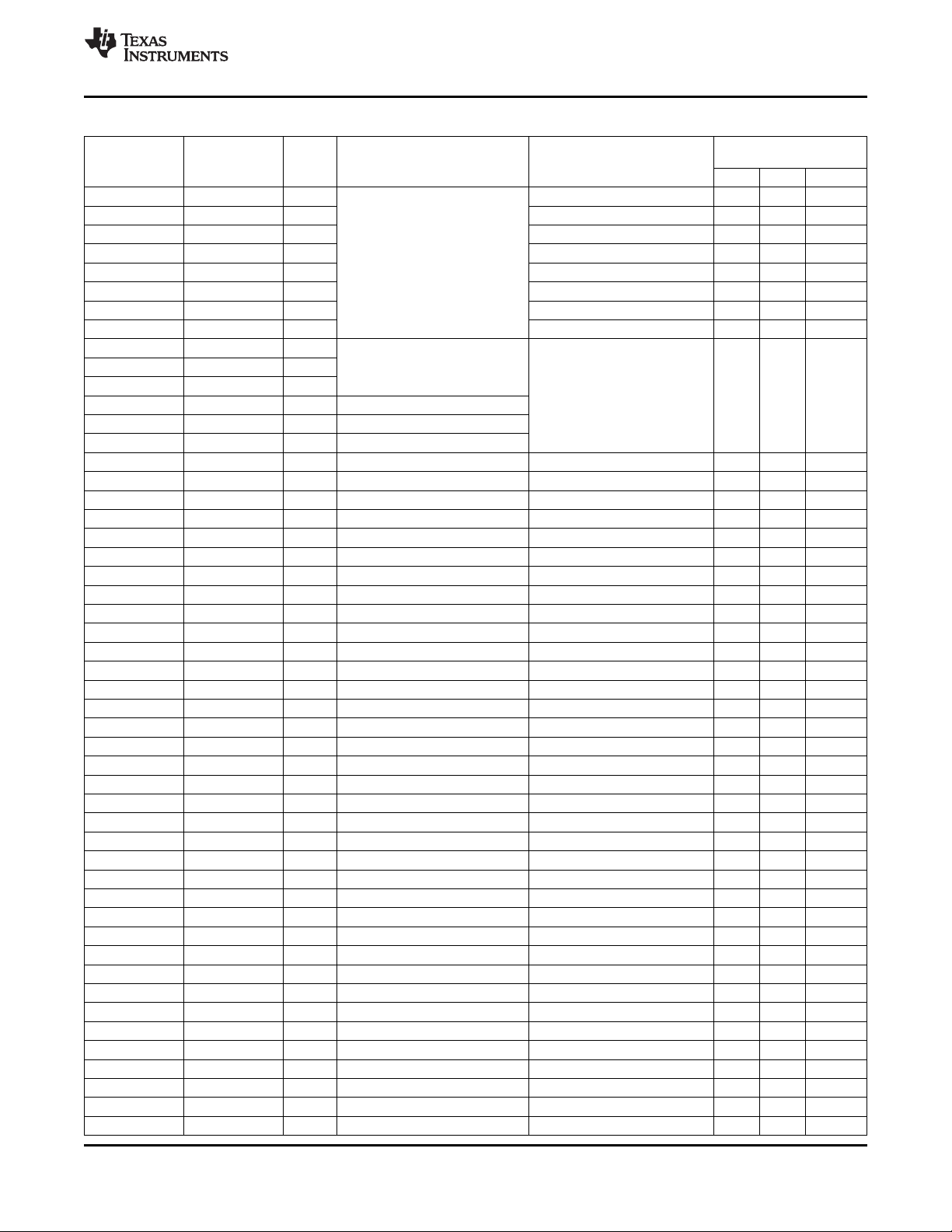
Table 3-3. Memory Map Summary
START END SIZE EDMA/
ADDRESS ADDRESS (Bytes) PERIPHERAL
0x0000 0000 0x0000 3FFF 16K ARM RAM0
0x0000 4000 0x0000 7FFF 16K ARM RAM1
0x0000 8000 0x0000 FFFF 32K ARM ROM (Instruction)
0x0001 0000 0x0001 3FFF 16K ARM RAM0 (Data)
0x0001 4000 0x0001 7FFF 16K ARM RAM1 (Data)
0x0001 8000 0x0001 FFFF 32K ARM ROM (Data)
0x0002 0000 0x000F FFFF 896K
0x0010 0000 0x003F FFFF 3M
0x0040 0000 0x004F FFFF 1M
0x0050 0000 0x005F FFFF 1M Reserved
0x0060 0000 0x006F FFFF 1M
0x0070 0000 0x007F FFFF 1M
0x0080 0000 0x0080 FFFF 64K
0x0081 0000 0x0081 7FFF 32K Reserved Hole (MPPA Disable)
0x0081 8000 0x0083 7FFF 128K L2 RAM/Cache
0x0083 8000 0x008F FFFF 800K Reserved
0x0090 0000 0x0092 FFFF 192K
0x0093 0000 0x009F FFFF 832K
0x00A0 0000 0x00DF FFFF 4M
0x00E0 0000 0x00E0 7FFF 32K L1P RAM/Cache
0x00E0 8000 0x00EF FFFF 992K Reserved
0x00F0 0000 0x00F0 7FFF 32K L1D RAM/Cache Reserved
0x00F0 8000 0x017F FFFF 9184K Reserved
0x0180 0000 0x01BB FFFF 3840K
0x01BC 0000 0x01BC 0FFF 4K ARM ETB Memory
0x01BC 1000 0x01BC 17FF 2K ARM ETB Registers
0x01BC 1800 0x01BC 18FF 256 ARM IceCrusher
0x01BC 1900 0x01BC 1BFF 768 Reserved
0x01BC 1C00 0x01BF FFFF 249K
0x01C0 0000 0x0FFF FFFF 228M CFG Bus Peripherals CFG Bus Peripherals CFG Bus Peripherals ✓
0x1000 0000 0x1000 FFFF 64K Reserved
0x1001 0000 0x1001 3FFF 16K ARM RAM0 (Data) ARM RAM0 (Data) ✓ ✓ ✓ ✓ ✓ ✓ ✓
0x1001 4000 0x1001 7FFF 16K ARM RAM1 (Data) ARM RAM1 (Data) ✓ ✓ ✓ ✓ ✓ ✓ ✓
0x1001 8000 0x1001 FFFF 32K ARM ROM (Data) ARM ROM (Data) ✓ ✓ ✓ ✓ ✓ ✓ ✓
0x1002 0000 0x10FF FFFF 16256K
0x1100 0000 0x113F FFFF 4M Reserved
0x1140 0000 0x114F FFFF 1M
0x1150 0000 0x115F FFFF 1M Reserved Reserved
0x1160 0000 0x116F FFFF 1M
0x1170 0000 0x117F FFFF 1M
0x1180 0000 0x1180 FFFF 64K
0x1181 0000 0x1181 7FFF 32K Reserved Hole (MPPA Disable)
0x1181 8000 0x1183 7FFF 128K L2 RAM/Cache L2 RAM/Cache L2 RAM/Cache ✓ ✓ ✓ ✓ ✓ ✓
0x1183 8000 0x118F FFFF 800K Reserved Reserved Reserved
0x1190 0000 0x11DF FFFF 5M
0x11E0 0000 0x11E0 7FFF 32K L1P RAM/Cache L1P RAM/Cache L1P RAM/Cache ✓ ✓ ✓ ✓ ✓
0x11E0 8000 0x11EF FFFF 992K Reserved Reserved Reserved
ARM C64x+
(Instruction)
(Instruction)
Reserved
Reserved Reserved
(2)
Reserved
CFG Space
(2)
Reserved
Video TSIF
Port (0/1)
MASTER PERIPHERAL ACCESSIBILITY
VDCE EMAC HPI PCI USB VLYNQ ATA
(3)✓(3)
(1)
(3)
✓
(1) These peripherals have their own DMA engine or master port interface to the DMSoC system bus and do not use the EDMA for data
transfers. The ✓ symbol indicates that the peripheral has a valid connection through the device switch fabric to the memory region
identified in the EDMA access column.
(2) MPPA should be used to disable the hole. For more information on MPPA, see the TMS320C64x+ DSP Megamodule Reference Guide
(SPRU871).
(3) The HPI's, PCI's, and VLYNQ's access to the configuration bus peripherals is limited, see Table 3-4, Configuration Memory Map
Summary for the details.
Copyright © 2007–2010, Texas Instruments Incorporated Device Overview 21
Submit Documentation Feedback
Product Folder Link(s): TMS320DM6467
Page 22
TMS320DM6467
SPRS403G–DECEMBER 2007–REVISED OCTOBER 2010
www.ti.com
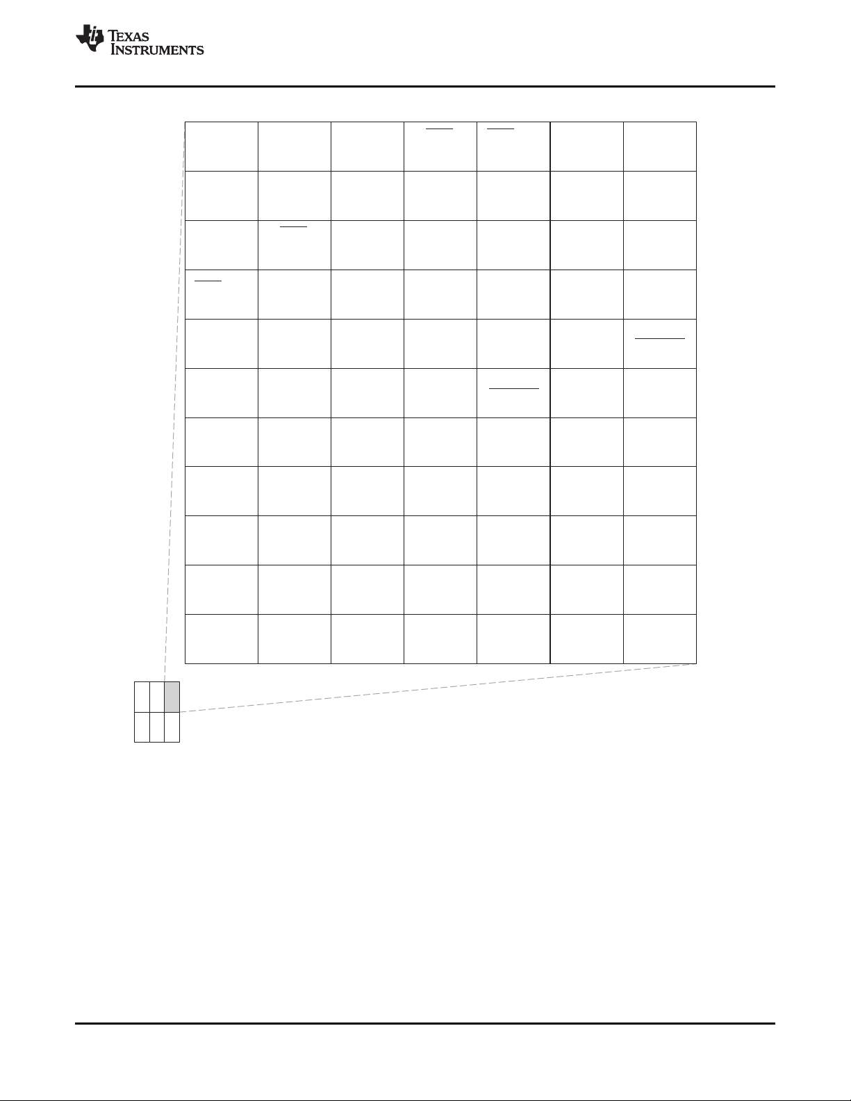
Table 3-3. Memory Map Summary (continued)
START END SIZE EDMA/
ADDRESS ADDRESS (Bytes) PERIPHERAL
ARM C64x+
Video TSIF
Port (0/1)
MASTER PERIPHERAL ACCESSIBILITY
VDCE EMAC HPI PCI USB VLYNQ ATA
0x11F0 0000 0x11F0 7FFF 32K L1D RAM/Cache L1D RAM/Cache L1D RAM/Cache ✓ ✓ ✓ ✓ ✓
0x11F0 8000 0x11FF FFFF 992K Reserved Reserved Reserved
0x1200 0000 0x1FFF FFFF 224M
0x2000 0000 0x2000 7FFF 32K DDR2 Control DDR2 Control DDR2 Control
0x2000 8000 0x2000 FFFF 32K EMIFA Control EMIFA Registers EMIFARegisters
0x2001 0000 0x2001 7FFF 32K VLYNQ Control VLYNQ Registers VLYNQ Registers
Registers Registers Registers
Registers
Registers
✓
0x2001 8000 0x200F FFFF 928K Reserved Reserved Reserved
0x2010 0000 0x2FFF FFFF 255M
0x3000 0000 0x3FFF FFFF 256M PCI Data PCI Data
0x4000 0000 0x403F FFFF 4M Reserved Reserved Reserved
0x4040 0000 0x4043 FFFF 256K
0x4044 0000 0x4047 FFFF 256K
0x4048 0000 0x404B FFFF 256K
0x404C 0000 0x404F FFFF 256K
0x4050 0000 0x405F FFFF 1M
0x4060 0000 0x4063 FFFF 256K Reserved Reserved Reserved
0x4064 0000 0x4067 FFFF 256K
0x4068 0000 0x406B FFFF 256K
0x406C 0000 0x406F FFFF 256K
0x4070 0000 0x41FF FFFF 25M
0x4200 0000 0x43FF FFFF 32M EMIFA Data (CS2)
0x4400 0000 0x45FF FFFF 32M EMIFA Data (CS3)
0x4600 0000 0x47FF FFFF 32M EMIFA Data (CS4)
0x4800 0000 0x49FF FFFF 32M EMIFA Data (CS5)
(4)
EMIFA Data (CS2)
(4)
EMIFA Data (CS3)
(4)
EMIFA Data (CS4)
(4)
EMIFA Data (CS5)
(4)
EMIFA Data (CS2)
(4)
EMIFA Data (CS3)
(4)
EMIFA Data (CS4)
(4)
EMIFA Data (CS5)
(4)
(4)
(4)
(4)
✓ ✓ ✓ ✓
✓ ✓ ✓ ✓
✓ ✓ ✓ ✓
✓ ✓ ✓ ✓
0x4A00 0000 0x4BFF FFFF 32M Reserved Reserved Reserved
0x4C00 0000 0x4FFF FFFF 64M VLYNQ (Remote Data) VLYNQ (Remote Data) VLYNQ (RemoteData) ✓ ✓ ✓ ✓ ✓ ✓ ✓
0x5000 0000 0x7FFF FFFF 768M Reserved Reserved Reserved
0x8000 0000 0x9FFF FFFF 512M DDR2 Memory DDR2 Memory DDR2 Memory ✓ ✓ ✓ ✓ ✓ ✓ ✓ ✓ ✓
0xA000 0000 0xBFFF FFFF 512M Reserved Reserved Reserved
0xC000 0000 0xFFFF FFFF 1G Reserved Reserved Reserved
(4) EMIFA CS0 and CS1 are not functionally supported on the DM6467, and therefore, are not pinned out.
(1)
22 Device Overview Copyright © 2007–2010, Texas Instruments Incorporated
Submit Documentation Feedback
Product Folder Link(s): TMS320DM6467
Page 23
TMS320DM6467
www.ti.com
SPRS403G–DECEMBER 2007–REVISED OCTOBER 2010
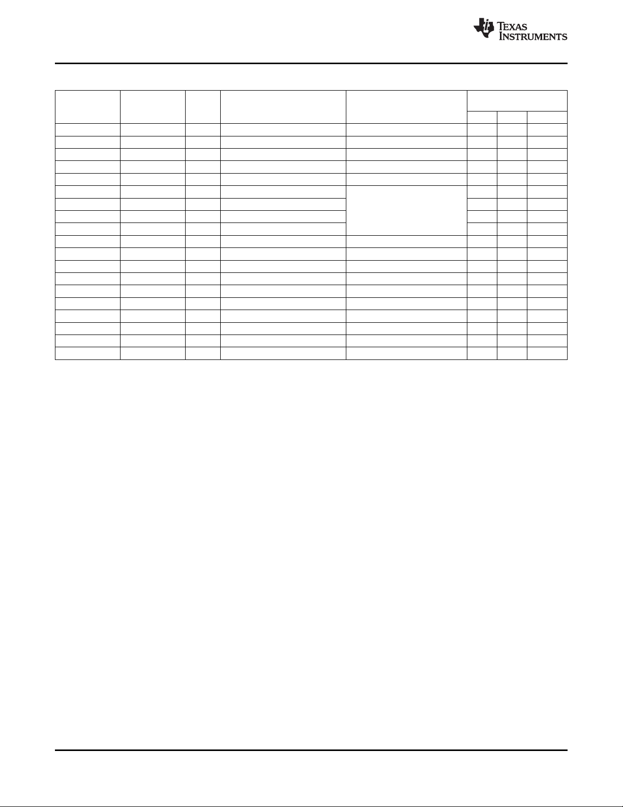
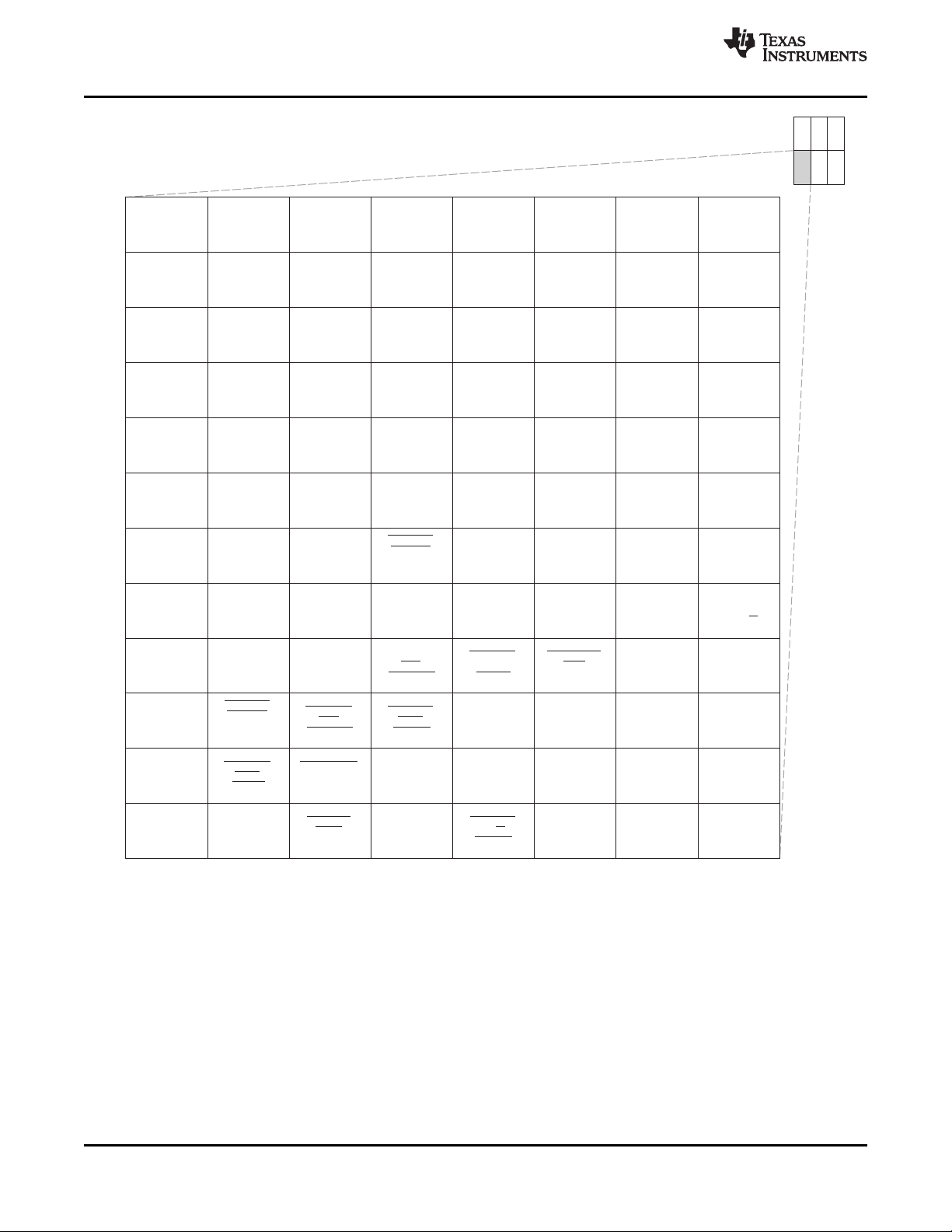
Table 3-4. Configuration Memory Map Summary
START END SIZE
ADDRESS ADDRESS (Bytes)
0x0180 0000 0x0180 FFFF 64K C64x+ Interrupt Controller
0x0181 0000 0x0181 0FFF 4K C64x+ Powerdown Controller
0x0181 1000 0x0181 1FFF 4K C64x+ Security ID
0x0181 2000 0x0181 2FFF 4K C64x+ Revision ID
0x0182 0000 0x0182 FFFF 64K C64x+ EMC
0x0183 0000 0x0183 FFFF 64K Reserved
0x0184 0000 0x0184 FFFF 64K C64x+ Memory System
0x0185 0000 0x01BB FFFF 3520K Reserved
0x01BC 0000 0x01BC 00FF 256
0x01BC 0100 0x01BC 01FF 256 ARM ETB Memory
0x01BC 0200 0x01BC 0FFF 3.5K
0x01BC 1000 0x01BC 17FF 2K ARM ETB Registers
0x01BC 1800 0x01BC 18FF 256 ARM Ice Crusher
0x01BC 1900 0x01BF FFFF 255744 Reserved
0x01C0 0000 0x01C0 FFFF 64K EDMA CC EDMA CC
0x01C1 0000 0x01C1 03FF 1K EDMA TC0 EDMA TC0
0x01C1 0400 0x01C1 07FF 1K EDMA TC1 EDMA TC1
0x01C1 0800 0x01C1 0BFF 1K EDMA TC2 EDMA TC2
0x01C1 0C00 0x01C1 0FFF 1K EDMA TC3 EDMA TC3
0x01C1 1000 0x01C1 1FFF 4K Reserved Reserved
0x01C1 2000 0x01C1 23FF 1K Video Port
0x01C1 2400 0x01C1 27FF 1K Reserved Reserved
0x01C1 2800 0x01C1 2FFF 2K VDCE
0x01C1 3000 0x01C1 33FF 1K TSIF0
0x01C1 3400 0x01C1 37FF 1K TSIF1
0x01C1 3800 0x01C1 9FFF 26K Reserved Reserved
0x01C1 A000 0x01C1 A7FF 2K PCI Control Registers
0x01C1 A800 0x01C1 FFFF 22K Reserved Reserved
0x01C2 0000 0x01C2 03FF 1K UART0 ✓ ✓ ✓
0x01C2 0400 0x01C2 07FF 1K UART1 ✓ ✓ ✓
0x01C2 0800 0x01C2 0BFF 1K UART2 ✓ ✓ ✓
0x01C2 0C00 0x01C2 0FFF 1K Reserved Reserved ✓ ✓ ✓
0x01C2 1000 0x01C2 13FF 1K I2C ✓ ✓ ✓
0x01C2 1400 0x01C2 17FF 1K Timer0 Timer0 ✓ ✓ ✓
0x01C2 1800 0x01C2 1BFF 1K Timer1 Timer1 ✓ ✓ ✓
0x01C2 1C00 0x01C2 1FFF 1K Timer2 (Watchdog) ✓ ✓ ✓
0x01C2 2000 0x01C2 23FF 1K PWM0 ✓ ✓ ✓
0x01C2 2400 0x01C2 27FF 1K PWM1 ✓ ✓ ✓
0x01C2 2800 0x01C2 5FFF 14K Reserved Reserved ✓ ✓ ✓
0x01C2 6000 0x01C2 63FF 1K CRGEN0 ✓ ✓ ✓
0x01C2 6400 0x01C2 67FF 1K CRGEN1 ✓ ✓ ✓
0x01C2 6800 0x01C3 FFFF 102K Reserved Reserved ✓ ✓ ✓
0x01C4 0000 0x01C4 07FF 2K System Module System Module ✓ ✓ ✓
0x01C4 0800 0x01C4 0BFF 1K PLL Controller 1 ✓ ✓ ✓
0x01C4 0C00 0x01C4 0FFF 1K PLL Controller 2 ✓ ✓ ✓
0x01C4 1000 0x01C4 1FFF 4K Power and Sleep Controller Power and Sleep Controller ✓ ✓ ✓
0x01C4 2000 0x01C4 7FFF 24K Reserved Reserved ✓ ✓ ✓
0x01C4 8000 0x01C4 83FF 1K ARM Interrupt Controller Reserved ✓ ✓ ✓
0x01C4 8400 0x01C6 3FFF 111K Reserved Reserved ✓ ✓ ✓
0x01C6 4000 0x01C6 5FFF 8K USB2.0 Registers / RAM ✓ ✓ ✓
Reserved
ARM/EDMA C64x+
Reserved
MASTER PERIPHERAL
ACCESSIBILITY
HPI PCI VLYNQ
Copyright © 2007–2010, Texas Instruments Incorporated Device Overview 23
Submit Documentation Feedback
Product Folder Link(s): TMS320DM6467
Page 24
TMS320DM6467
SPRS403G–DECEMBER 2007–REVISED OCTOBER 2010
Table 3-4. Configuration Memory Map Summary (continued)
START END SIZE
ADDRESS ADDRESS (Bytes)
0x01C6 6000 0x01C6 67FF 2K ATA ✓ ✓ ✓
0x01C6 6800 0x01C6 6FFF 2K SPI ✓ ✓ ✓
0x01C6 7000 0x01C6 77FF 2K GPIO ✓ ✓ ✓
0x01C6 7800 0x01C6 7FFF 2K HPI HPI ✓ ✓ ✓
0x01C6 8000 0x01C7 FFFF 96K Reserved Reserved ✓ ✓ ✓
0x01C8 0000 0x01C8 0FFF 4K EMAC Control Registers ✓ ✓ ✓
0x01C8 1000 0x01C8 1FFF 4K EMAC Control Module Registers ✓ ✓ ✓
0x01C8 2000 0x01C8 3FFF 8K EMAC Control Module RAM ✓ ✓ ✓
0x01C8 4000 0x01C8 47FF 2K MDIO Control Registers ✓ ✓ ✓
0x01C8 4800 0x01D0 0FFF 498K Reserved Reserved ✓ ✓ ✓
0x01D0 1000 0x01D0 13FF 1K McASP0 Registers McASP0 Registers ✓ ✓ ✓
0x01D0 1400 0x01D0 17FF 1K McASP0 Data Port McASP0 Data Port ✓ ✓ ✓
0x01D0 1800 0x01D0 1BFF 1K McASP1 Registers McASP1 Registers ✓ ✓ ✓
0x01D0 1C00 0x01D0 1FFF 1K McASP1 Data Port McASP1 Data Port ✓ ✓ ✓
0x01D0 2000 0x01DF FFFF 1016K Reserved Reserved
0x01E0 0000 0x01FF FFFF 2M Reserved Reserved
0x0200 0000 0x021F FFFF 2M Reserved Reserved
0x0220 0000 0x023F FFFF 2M Reserved Reserved
0x0240 0000 0x0FFF FFFF 220M Reserved Reserved
ARM/EDMA C64x+
Reserved
MASTER PERIPHERAL
ACCESSIBILITY
HPI PCI VLYNQ
www.ti.com
3.6 Pin Assignments
Extensive use of pin multiplexing is used to accommodate the largest number of peripheral functions in
the smallest possible package. Pin multiplexing is controlled using a combination of hardware
configuration at device reset and software programmable register settings. For more information on pin
muxing, see Section 4.7, Multiplexed Pin Configurations, of this document.
3.6.1 Pin Map (Bottom View)
Figure 3-2 through Figure 3-7 show the bottom view of the package pin assignments in six quadrants (A,
B, C, D, E, and F).
24 Device Overview Copyright © 2007–2010, Texas Instruments Incorporated
Submit Documentation Feedback
Product Folder Link(s): TMS320DM6467
Page 25

V
SS
V
SS
GP[4]/
STC_CLKIN
VP_DOUT1/
BTMODE1
VP_DOUT6/
DSPBOOT
VP_DOUT5/
PCIEN
VP_DOUT14/
TS1_PSTIN
VP_DOUT9/
TS1_ENAO
V
SS
AHCLKR0
GP[3]/
AUDIO_CLK0
TOUT1U
VP_DOUT0/
BTMODE0
VP_DOUT3/
BTMODE3
VP_DOUT7/
VADJEN
VP_DOUT15/
TS1_DIN
ACLKX0 ACLKR0
AMUTEIN0
GP[2]/
AUDIO_CLK1
TOUT1L
TINP0U
VP_DOUT4/
CS2BW
VP_DOUT12/
TS1_WAITO
AHCLKX0
AMUTE0
AFSR0 AFSX0
TOUT2
TINP1L
TINP0L
VP_DOUT2/
BTMODE2
ACLKX1 AHCLKX1
AXR0[3] AXR0[2]
GP[0]
RESET
TOUT0U TOUT0L
SPI_CLK
AXR1[0]
AXR0[0] AXR0[1]
GP[1]
V
SS
DV
DD33
DV
DD33
VLYNQ_
CLOCK
VLYNQ_
SCRUN
SPI_CS1
SDA SCL
DV
DD33
CV
DD
VLYNQ_TXD1 VLYNQ_TXD2 VLYNQ_TXD3
SPI_CS0
SPI_EN
1 2
AC
AB
AA
Y
W
V
U
T
MTCLK
VLYNQ_RXD2 VLYNQ_RXD3 VLYNQ_TXD0 SPI_SOMI
MTXD7 GMTCLK
VLYNQ_RXD1 VLYNQ_RXD0 SPI_SIMO
MTXD3 MTXD4
MTXD5
MTXD6
R
P
N
3 4 5 6 7 8
1 2 3 4 5 6 7 8
AC
AB
AA
Y
W
V
U
T
R
P
N
V
SS
V
SS
DV
DD33
CV
DD
CV
DD
DV
DD33
V
SS
V
SS
CV
DD
CV
DD
V
SS
V
SS
V
SS
V
SS
A B C
D E F
TMS320DM6467
www.ti.com
SPRS403G–DECEMBER 2007–REVISED OCTOBER 2010
Figure 3-2. Pin Map [Section A]
Copyright © 2007–2010, Texas Instruments Incorporated Device Overview 25
Submit Documentation Feedback
Product Folder Link(s): TMS320DM6467
Page 26
A B C
D E F
VP_CLKIN3/
TS1_CLKO
VP_CLKO3/
TS0_CLKO
TS1_CLKIN
UCTS0/
USD0
VP_CLKIN0
VP_DIN4/
TS0_DOUT4/
TS1_WAITO
VP_DIN0/
TS0_DOUT0
VP_DIN8/
TS0_DIN0
VP_DOUT8/
TS1_WAITIN
VP_DOUT11/
TS1_DOUT
UDSR0/
TS0_PSTO/
GP[37]
V
SS
URXD0/
TS1_DIN
VP_DIN5/
TS0_DOUT5/
TS1_EN_WAITO
VP_DIN1/
TS0_DOUT1
VP_DIN9/
TS0_DIN1
VP_CLKO2
VP_DOUT10/
TS1_PSTO
UDCD0/
TS0_WAITIN/
GP[38]
DV
DD33
URTS0/
UIRTX0/
TS1_EN_WAITO
VP_DIN6/
TS0_DOUT6/
TS1_PSTIN
VP_DIN2/
TS0_DOUT2
VP_DIN10/
TS0_DIN2
VP_DOUT13/
TS1_EN_WAITO
VP_CLKIN2
URIN0/
GP[8]/
TS1_WAITIN
UDTR0/
TS0_ENAO/
GP[36]
UTXD0/
URCTX0/
TS1_PSTIN
VP_DIN7/
TS0_DOUT7/
TS1_DIN
VP_DIN3/
TS0_DOUT3
VP_DIN11/
TS0_DIN3
DV
DD33
CV
DD
9 10
AC
AB
AA
Y
W
V
U
T
R
P
N
11 12 13 14 15 16
9 10 11 12 13 14 15 16
AC
AB
AA
Y
W
V
U
T
R
P
N
DV
DD33
DV
DD33
DV
DD33
DV
DD33
DV
DD33
DV
DD33
DV
DD33
CV
DD
CV
DD
CV
DD
CV
DD
CV
DD
CV
DD
CV
DD
V
SS
V
SS
V
SS
V
SS
CV
DD
CV
DD
CV
DD
CV
DD
CV
DD
CV
DD
CV
DD
CV
DD
V
SS
CV
DD
CV
DD
CV
DD
V
SS
V
SS
CV
DD
CV
DD
CV
DD
CV
DD
CV
DD
CV
DD
V
SS
V
SS
CV
DD
CV
DD
CV
DD
CV
DD
CV
DD
CV
DD
V
SS
V
SS
V
SS
V
SS
V
SS
V
SS
V
SS
V
SS
TMS320DM6467
SPRS403G–DECEMBER 2007–REVISED OCTOBER 2010
www.ti.com
Figure 3-3. Pin Map [Section B]
26 Device Overview Copyright © 2007–2010, Texas Instruments Incorporated
Submit Documentation Feedback
Product Folder Link(s): TMS320DM6467
Page 27
VP_DIN12/
TS0_DIN4
VP_DIN15_
VP_VSYNC/
TS0_DIN7
TS0_CLKIN
URTS2/
UIRTX2/
TS0_PSTIN/
GP[41]
UCTS2/USD2/
CRG0_VCXI/
GP[42]/
TS1_PSTO
V
SS
VP_DIN13_
FIELD/
TS0_DIN5
VP_CLKIN1
UTXD1/
URCTX1/
TS0_DOUT7/
GP[24]
V
SS
DDR_D[23]
VP_DIN14_
VP_HSYNC/
TS0_DIN6
URTS1/
UIRTX1/
TS0_WAITO/
GP[25]
UTXD2/URCTX2/
CRG1_PO/
GP[40]/
CRG0_PO
DV
DDR2
DDR_D[28] DDR_D[21] DDR_D[20]
UCTS1/USD1/
TS0_EN_WAITO/
GP[26]
URXD1/
TS0_DIN7/
GP[23]
DDR_D[31] DDR_D[29] DDR_D[22]
DDR_DQM[2]
PWM0/
CRG0_PO/
TS1_ENAO
17 18
AC
AB
AA
Y
W
V
U
T
R
P
N
19 20 21 22 23
17 18 19 20 21 22 23
AC
AB
AA
Y
W
V
U
T
R
P
N
A B C
D E F
PWM1/
TS1_DOUT
V
SS
DDR_D[30] DV
DDR2
V
SS
DDR_DQS[2]
DDR_D[19]DDR_DQS[2]DDR_DQS[3]DDR_DQM[3]V
SS
V
SS
DDR_DQS[3] DDR_D[27]DV
DDR2
DDR_D[24]
DDR_D[18]DDR_D[16]V
SS
V
SS
DV
DDR2
V
SS
DV
DDR2
DDR_A[10]DDR_D[17]DDR_D[26]
DDR_D[25]
DV
DDR2
DDR_DQGATE2 DDR_A[1]DDR_A[3]DDR_DQGATE3
DDR_A[12]
DDR_BA[2] DDR_VREFV
SS
DV
DDR2
DDR_A[14]DDR_A[9]DDR_A[5]DDR_A[7]DDR_BA[0]V
SS
V
SS
V
SS
V
SS
DV
DD33
DV
DDR2
V
SS
URXD2/
CRG1_VCXI/
GP[39]/
CRG0_VCXI
V
SS
V
SS
TMS320DM6467
www.ti.com
SPRS403G–DECEMBER 2007–REVISED OCTOBER 2010
Figure 3-4. Pin Map [Section C]
Copyright © 2007–2010, Texas Instruments Incorporated Device Overview 27
Submit Documentation Feedback
Product Folder Link(s): TMS320DM6467
Page 28
MTXD0
MTXEN
MCRS
MCOL
MRCLK MRXD7
MRXD6
V
SS
MRXD4
MRXD3
MRXD2
MRXDV
RFTCLK
MRXD1
MRXER
MDIO
MDCLK
DV
DD33
1 2
L
K
J
H
G
F
E
D
C
B
A
3 4 5 6 7 8
1 2 3 4 5 6 7 8
L
K
J
H
G
F
E
D
C
B
A
A B C
D E F
DV
DD33
PCI_AD0/
HD0/
EM_D0
PCI_AD2/
HD2/
EM_D2
PCI_AD4/
HD4/
EM_D4
V
SS
DV
DD33
CV
DD
V
SS
V
SS
PCI_AD9/
HD9/
EM_D9
PCI_CBE0
ATA_CS0//
GP[33]/
EM_A[18]
PCI_AD6/
HD6/
EM_D6
PCI_AD3/
HD3/
EM_D3
PCI_AD1/
HD1/
EM_D1
PCI_AD13/
HD13/
EM_D13
PCI_AD15/
HD15/
EM_D15
PCI_AD11/
HD11/
EM_D11
PCI_PAR/
/HAS
EM_DQM0
PCI_IDSEL/
HDDIR/
EM_R/W
PCI_AD18/
DD2/
HD18/
EM_A[2]
PCI_TRDY/
HHWIL/
EM_A[16]/(ALE)
PCI_AD7/
HD7/
EM_D7
PCI_AD5/
HD5/
EM_D5
PCI_AD10/
HD10/
EM_D10
PCI_AD8/
HD8/
EM_D8
PCI_AD12/
HD12/
EM_D12
PCI_AD24/
DD8/
HD24/
EM_A[8]
PCI_AD20/
DD4/
HD20/
EM_A[4]
PCI_FRAME
HINT//
EM_BA[0]
PCI_STOP
EM_WE
/
HCNTL0/
PCI_AD26/
DD10/
HD26/
EM_A[10]
PCI_CBE2
HDS2
EM_CS2
/
/
PCI_CBE1
ATA_CS1//
GP[32]/
EM_A[19]
PCI_AD14/
HD14/
EM_D14
PCI_PERR
HCS
EM_DQM1
/
/
PCI_AD22/
DD6/
HD22/
EM_A[6]
PCI_AD16/
DD0/
HD16/
EM_A[0]
PCI_AD21/
DD5/
HD21/
EM_A[5]
PCI_AD29/
DD13/
HD29/
EM_A[13]
PCI_AD17/
DD1/
HD17/
EM_A[1]
PCI_SERR
HDS1
EM_OE
/
/
V
SS
PCI_DEVSEL/
HCNTL1/
EM_BA[1]
PCI_AD25/
DD9/
HD25/
EM_A[9]
PCI_AD23/
DD7/
HD23/
EM_A[7]
PCI_AD31/
DD15/
HD31/
EM_A[15]
V
SS
PCI_AD27/
DD11/
HD27/
EM_A[11]
PCI_CBE3
W
EM_CS3
/
HR/ /
PCI_AD19/
DD3/
HD19/
EM_A[3]
PCI_IRDY
HRDY//
EM_A[17]/(CLE)
RSV2RSV1
MTXD1 MTXD2
M M
V
SS
V
SS
V
SS
V
SS
V
SS
V
SS
V
SS
V
SS
CV
DD
DV
DD33
DV
DD33
V
SS
MRXD5
V
SS
DV
DD33
CV
DD
CV
DD
CV
DD
CV
DD
DV
DD33
V
SS
MRXD0
DV
DD33
TMS320DM6467
SPRS403G–DECEMBER 2007–REVISED OCTOBER 2010
www.ti.com
Figure 3-5. Pin Map [Section D]
Submit Documentation Feedback
Product Folder Link(s): TMS320DM6467
28 Device Overview Copyright © 2007–2010, Texas Instruments Incorporated
Page 29
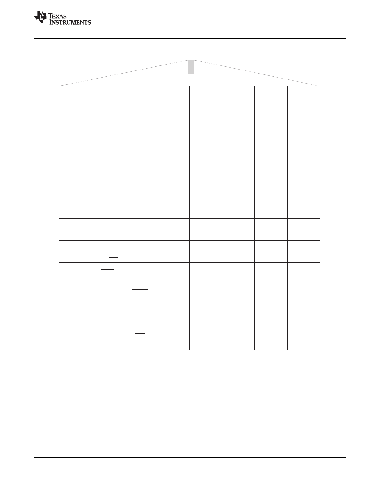
A B C
D E F
V
SS
DV
DD33
9 10
L
K
J
H
G
F
E
D
C
B
A
11 12 13 14 15 16
9 10 11 12 13 14 15 16
L
K
J
H
G
F
E
D
C
B
A
RSV7
TRST
TDI
GP[6]/
CVDDADJ0
TMS
AUX_CV
DD
DEV_CV
DD
DEV_DV
SS
PCI_RSV3
/
GP[19]/
EM_WAIT5/
(RDY5/ )
DIOR
BSY5
PCI_RSV1/
DA0/
GP[17]/
EM_A[20]
PCI_GNT
DMACK
EM_CS4
/
/
GP[12]/
PCI_AD28/
DD12/
HD28/
EM_A[12]
PCI_RSV5/
IORDY/
GP[21]/
EM_WAIT3/
(RDY3/ )BSY3
AUX_DV
DD18
DEV_DV
DD18
RSV5
TDO
AUX_DV
SS
RTCK
PCI_RST/
DA2/
GP[13]/
EM_A[22]
PCI_AD30/
DD14/
HD30/
EM_A[14]
PCI_INTA
BSY2
/
EM_WAIT2/
(RDY2/ )
DEV_V
SS
PLL1V
SS
CLKOUT0
TCK
PCI_RSV2/
INTRQ/
GP[18]/
EM_RSV0
PCI_REQ
EM_CS5
/
DMARQ/
GP[11]/
GP[5]
PLL1V
DD18
EMU1
PLL2V
SS
V
SS
DEV_MXO
EMU0
GP[7]/
CVDDADJ1
PCI_RSV4/
/
GP[20]/
EM_WAIT4/
(RDY4/ )
DIOW
BSY4
PCI_CLK/
GP[10]
PCI_RSV0/
DA1/
GP[16]/
EM_A[21]
M M
V
SS
V
SS
V
SS
V
SS
V
SS
V
SS
V
SS
V
SS
CV
DD
V
SS
CV
DD
CV
DD
V
SS
DEV_MXI/
DEV_CLKIN
V
SS
V
SS
V
SS
V
SS
V
SS
V
SS
V
SS
CV
DD
CV
DD
CV
DD
CV
DD
CV
DD
CV
DD
CV
DD
V
SS
CV
DD
CV
DD
CV
DD
CV
DD
CV
DD
CV
DD
CV
DD
CV
DD
V
SS
V
SS
V
SS
CV
DD
CV
DD
CV
DD
CV
DD
CV
DD
CV
DD
CV
DD
DV
DD33
DV
DD33
DV
DD33
DV
DD33
DV
DD33
DV
DD33
DV
DD33
PLL2V
DD18
TMS320DM6467
www.ti.com
SPRS403G–DECEMBER 2007–REVISED OCTOBER 2010
Copyright © 2007–2010, Texas Instruments Incorporated Device Overview 29
Figure 3-6. Pin Map [Section E]
Submit Documentation Feedback
Product Folder Link(s): TMS320DM6467
Page 30
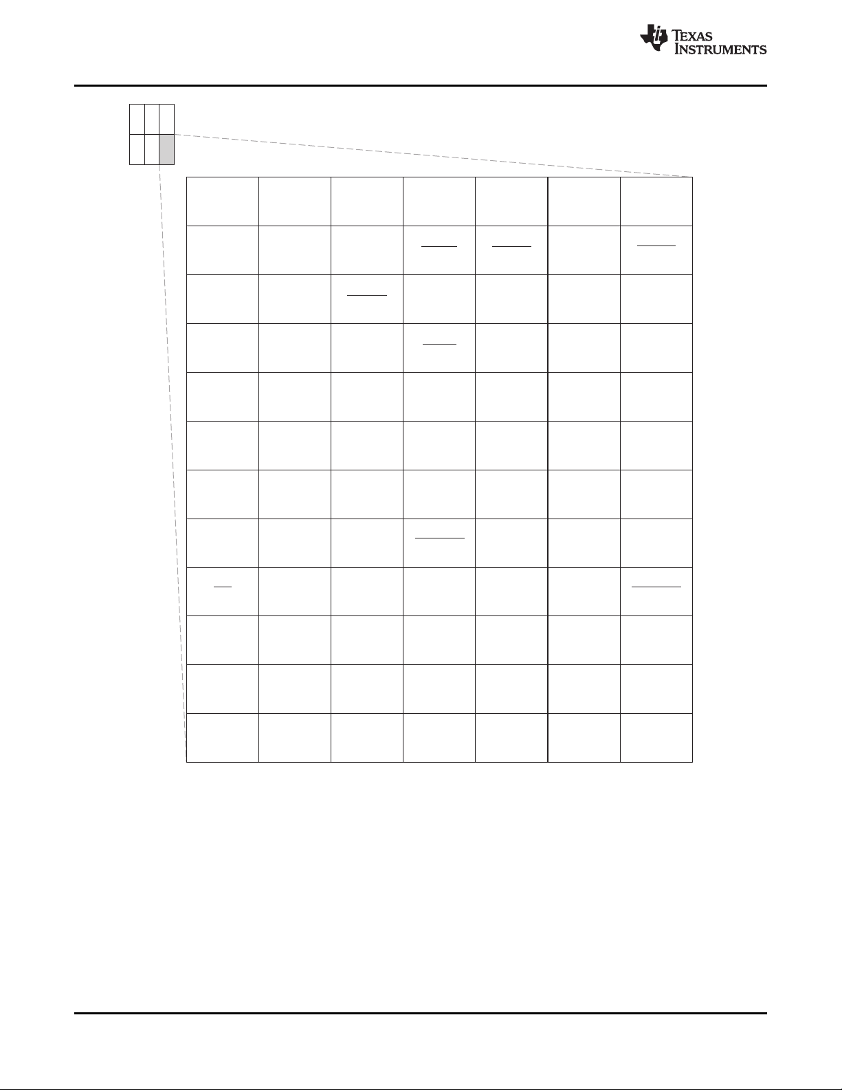
DDR_A[2]
DDR_CLK
DDR_ZP
DDR_WE
DDR_CAS
V
SS
DV
DDR2
DDR_RAS
DV
DDR2
DDR_A[11]
DDR_DQGATE0 DDR_CS DDR_DQGATE1 DDR_A[4] DDR_A[8]
DDR_D[7] DDR_A[13] DDR_D[15]
DDR_A[0]
DV
DDR2
17 18
L
K
J
H
G
F
E
D
C
B
A
19 20 21 22 23
17 18 19 20 21 22 23
L
K
J
H
G
F
E
D
C
B
A
A B C
D E F
DV
DDR2
DDR_D[4] DDR_D[6] DDR_D[13] DDR_D[14]
DDR_D[12]DDR_DQM[1]DDR_D[5]DDR_DQM[0]V
SS
USB_V
DDA3P3
DDR_DQS[0]
DV
DDR2
V
SS
DDR_D[1]
DDR_D[11]USB_V
DD1P8
USB_
V
DDA1P2LDO
USB_R1POR
V
SS
DDR_DQS[1]DDR_DQS[1]DDR_DQS[0]
DDR_D[2]
USB_V
SSREF
DDR_D[8]DDR_D[10]DDR_D[0]
DDR_D[3]
USB_
DRVVBUS/
GP[22]
DDR_D[9]
V
SS
DV
DDR2
RSV4RSV3USB_DNUSB_DPV
SS
AUX_MXO
V
SS
AUX_MXI/
AUX_CLKIN
RSV6
AUX_V
SS
V
SS
DDR_ODT0
V
SS
V
SS
DDR_A[6]
DDR_CLKDDR_ZN DDR_CKE
DDR_BA[1]
V
SS
M M
V
SS
V
SS
DV
DDR2
V
SS
DV
DDR2
V
SS
V
SS
V
SS
V
SS
V
SS
TMS320DM6467
SPRS403G–DECEMBER 2007–REVISED OCTOBER 2010
www.ti.com
Figure 3-7. Pin Map [Section F]
3.7 Terminal Functions
The terminal functions tables (Table 3-5 through Table 3-32) identify the external signal names, the
associated pin (ball) numbers along with the mechanical package designator, the pin type, whether the pin
has any internal pullup or pulldown resistors, and a functional pin description. For more detailed
information on device configuration, peripheral selection, multiplexed/shared pin, and see the Device
Configurations section of this data manual.
30 Device Overview Copyright © 2007–2010, Texas Instruments Incorporated
Submit Documentation Feedback
Product Folder Link(s): TMS320DM6467
Page 31

TMS320DM6467
www.ti.com
SPRS403G–DECEMBER 2007–REVISED OCTOBER 2010
3.7.1 BOOT
Table 3-5. BOOT Terminal Functions
SIGNAL
NAME NO.
TYPE
(1)
ARM Boot Mode configuration bits. These pins are multiplexed between ARM boot mode and the Video Port Interface (VPIF). At reset, the
boot mode inputs BTMODE[3:0] are sampled to determine the ARM boot configuration. See below the boot modes set by these inputs. For
more details on the types of boot modes, see the Section 4.4.1, Boot Modes. After reset, these pins are Video port data outputs 3 through 0
(VP_DOUT[3:0]).
VP_DOUT0/ IPD
BTMODE0 DV
VP_DOUT1/ IPD
BTMODE1 DV
VP_DOUT2/ IPD
BTMODE2 DV
VP_DOUT3/ IPD
BTMODE3 DV
VP_DOUT4/ IPD
CS2BW DV
VP_DOUT5/ IPD
PCIEN DV
AB5 I/O/Z
AC4 I/O/Z
Y8 I/O/Z
AB6 I/O/Z 1110 SPI Boot
AA7 I/O/Z
AC6 I/O/Z
OTHER
(3)
DD33
DD33
DD33
DD33
DD33
DD33
(2)
DESCRIPTION
BOOT
BTMODE[3:0] ARM Boot Mode
0000 Emulation Boot (PCIEN = 0)
0001 Reserved
HPI Boot (16-Bit width) (if PCIEN = 0)
0010 or
PCI Boot without auto-initialization (if PCIEN = 1)
HPI Boot (32-Bit width) (if PCIEN = 0)
0011 or
PCI Boot with auto-initialization (if PCIEN = 1)
0100
EMIFA Direct Boot (ROM/NOR) (PCIEN = 0) [error if PCIEN =
1; defaults to UART0]
0101 Reserved
0110 I2C Boot
0111 NAND Flash Boot (PCIEN = 0) [error if PCIEN = 1]
1000 UART0 Boot
1001 Reserved
1010 Reserved
1011 Reserved
1100 - 1101 Reserved
1111 Reserved
DEVICE CONTROL
EMIFA CS2 space data bus width. This pin is multiplexed between EMIFA control
and the VPIF. At reset, the input state is sampled to set the EMIFA data bus width
for the CS2 (boot) chip select region.
For an 8-bit-wide EMIFA data bus, CS2BW = 0.
For a 16-bit-wide EMIFA data bus, CS2BW = 1.
After reset, this pin is video port data output 4 (VP_DOUT4).
PCI Enable. This pin is multiplexed between PCI Control and the VPIF. At reset, the
input state is sampled to enable/disable the PCI interface pin multiplexing. Note:
When PCI boot mode is not used, for proper device operation out of reset PCIEN
must be "0".
0 = PCI pin function is disabled; EMIFA or HPI pin function enabled
1 = PCI pin function is enabled
After reset, this pin is video port data output 5 (VP_DOUT5).-
(1) I = Input, O = Output, Z = High impedance, S = Supply voltage, GND = Ground, A = Analog signal
(2) IPD = Internal pulldown, IPU = Internal pullup. For more detailed information on pullup/pulldown resistors and situations where external
pullup/pulldown resistors are required, see Section 4.8.1, Pullup/Pulldown Resistors.
(3) Specifies the operating I/O supply voltage for each signal
Copyright © 2007–2010, Texas Instruments Incorporated Device Overview 31
Submit Documentation Feedback
Product Folder Link(s): TMS320DM6467
Page 32

TMS320DM6467
SPRS403G–DECEMBER 2007–REVISED OCTOBER 2010
Table 3-5. BOOT Terminal Functions (continued)
SIGNAL
NAME NO.
VP_DOUT6/ IPD The DSP is booted by the ARM when DSPBOOT = 0.
DSPBOOT DV
VP_DOUT7 / IPD
VADJEN DV
AC5 I/O/Z
AB7 I/O/Z
TYPE
(1)
OTHER
(3)
DD33
DD33
(2)
DESCRIPTION
DSP boot source bit. This pin is multiplexed between DSP boot and the VPIF. At
reset, the input state is sampled to set the DSP boot source DSPBOOT.
The DSP boots from EMIFA when DSPBOOT = 1 (and ARM HPI or PCI boot mode
is not selected).
After reset, this pin is video port data output 6 (VP_DOUT6).
Voltage Adjust Enable (SmartReflex). This pin is multiplexed between SmartReflex
Output Control Enable and the VPIF. At reset, the input state is sampled to
determine whether the SmartReflex Control Outputs are enbabled or disabled.
0 = SmartReflex outputs disabled [default]. GP[6]/CVDDADJ0 and
GP[7]/CVDDADJ1 pins function as GPIO.
1 = SmartReflex outputs enabled. GP[6]/CVDDADJ0 and GP[7]/CVDDADJ1 pins
function as SmartReflex control outputs to the adjustable core power supply [1.2 V
or 1.05 V].
www.ti.com
32 Device Overview Copyright © 2007–2010, Texas Instruments Incorporated
Submit Documentation Feedback
Product Folder Link(s): TMS320DM6467
Page 33

TMS320DM6467
www.ti.com
SPRS403G–DECEMBER 2007–REVISED OCTOBER 2010
3.7.2 Oscillator/PLL
Table 3-6. Oscillator/PLL Terminal Functions
SIGNAL
NAME NO.
DEV_MXI/ Crystal input DEV_MXI for DEV oscillator (system oscillator, typically 27 MHz). If the
DEV_CLKIN internal oscillator is bypassed, this pin is the 1.8-V external oscillator clock input.
B15 I DEV_DV
DEV_MXO A15 O DEV_DV
DEV_DV
DEV_DV
DEV_CV
DEV_V
DD18
SS
DD
SS
AUX_MXI/ McASP1/0). If the internal oscillator is bypassed, this pin is the 1.8-V external
AUX_CLKIN oscillator clock input. When the peripheral is not used, AUX_MXI should be left as a
D15 S
E14 GND
E15 S
C15 GND
B17 I AUX_DV
AUX_MXO A17 O AUX_DV
AUX_DV
AUX_DV
AUX_CV
AUX_V
PLL1V
PLL2V
PLL1V
PLL2V
DD18
SS
DD
SS
DD18
DD18
SS
SS
D16 S
C16 GND
E16 S
C17 GND
B14
B16
C14
A16
(1) I = Input, O = Output, Z = High impedance, S = Supply voltage, GND = Ground, A = Analog signal
(2) Specifies the operating I/O supply voltage for each signal
(3) For more information, see the Recommended Operating Conditions table
TYPE
S
GND
(1)
OTHER
(2)
DESCRIPTION
OSCILLATOR, PLL
DD18
Crystal output for DEV oscillator. If the internal oscillator is bypassed, DEV_MXO
DD18
should be left as a No Connect.
(3)
(3)
(3)
(3)
1.8-V power supply for DEV oscillator. If the internal oscillator is bypassed,
DEV_DV
should still be connected to the 1.8-V power supply.
DD18
I/O ground for DEV oscillator. If the internal oscillator is bypassed, DEV_DV
should be connected to ground VSS.
1.2-/1.05-V power supply for DEV oscillator. If the internal oscillator is bypassed,
DEV_CVDDshould be connected to the 1.2-/1.05-V power supply (CVDD).
Ground for DEV oscillator. Connect to crystal load capacitors. Do not connect to
board ground (VSS). If the internal oscillator is bypassed, DEV_VSSshould still be
connected to ground VSS.
Crystal input for Auxiliary (AUX) oscillator (24/48 MHz for USB, and UART2/1/0 and
DD18
No Connect.
Crystal output for AUX oscillator. If the internal oscillator is bypassed, AUX_MXO
should be left as a No Connect. When the peripheral is not used, AUX_MXO should
DD18
be left as a No Connect.
1.8-V power supply for AUX oscillator. If the internal oscillator is bypassed,
(3)
AUX_DV
peripheral is not used, AUX_DV
supply.
(3)
I/O ground for AUX oscillator. If the internal oscillator is bypassed, AUX_DV
should be connected to ground (VSS). When the peripheral is not used, AUX_DV
should still be connected to the 1.8-V power supply. When the
DD18
should be connected to the 1.8-V power
DD18
should be connected to ground (VSS).
1.2-/1.05-V power supply for AUX oscillator. If the internal oscillator is bypassed,
(3)
AUX_CVDDshould be connected to the 1.2-/1.05-V power supply (CVDD). When the
peripheral is not used, AUX_CVDDshould be connected to the 1.2-/1.05-V power
supply (CVDD).
Ground for AUX oscillator. Connect to crystal load capacitors. Do not connect to
(3)
board ground (VSS). If the internal oscillator is bypassed, AUX_VSSshould still be
connected to ground (VSS). When the peripheral is not used, AUX_VSSshould be
connected to ground (VSS).
(3)
(3)
1.8-V power supply for PLLs.
Ground for PLLs.
SS
SS
SS
Copyright © 2007–2010, Texas Instruments Incorporated Device Overview 33
Submit Documentation Feedback
Product Folder Link(s): TMS320DM6467
Page 34

TMS320DM6467
SPRS403G–DECEMBER 2007–REVISED OCTOBER 2010
www.ti.com
3.7.3 Clock Generator
Table 3-7. Clock Generator Terminal Functions
SIGNAL
NAME NO.
CLKOUT0 C13 O/Z DV
GP[3]/ IPD This pin is multiplexed between GPIO and the Audio Clock Selector. For the audio
AUDIO_CLK0 DV
GP[2]/ IPD This pin is multiplexed between GPIO and the Audio Clock Selector. For the audio
AUDIO_CLK1 DV
GP[4]/ IPD
STC_CLKIN DV
AB3 I/O/Z
AA4 I/O/Z
AC3 I/O/Z pin is the STC_CLKIN which can be used as an external clock source for the TSIF
(1) I = Input, O = Output, Z = High impedance, S = Supply voltage, GND = Ground, A = Analog signal
(2) IPD = Internal pulldown, IPU = Internal pullup. For more detailed information on pullup/pulldown resistors and situations where external
pullup/pulldown resistors are required, see Section 4.8.1, Pullup/Pulldown Resistors.
(3) Specifies the operating I/O supply voltage for each signal
TYPE
(1)
OTHER
DD33
DD33
DD33
DD33
(2) (3)
DESCRIPTION
CLOCK GENERATOR
Configurable output clock.
clock selector, this pin is the configurable AUDIO_CLK0 output.
clock selector, this pin is the configurable AUDIO_CLK1 output.
This pin is multiplexed between GPIO and the TSIF Clock Selector. For TSIF, this
counters or as TSIF output clock.
34 Device Overview Copyright © 2007–2010, Texas Instruments Incorporated
Submit Documentation Feedback
Product Folder Link(s): TMS320DM6467
Page 35

TMS320DM6467
www.ti.com
SPRS403G–DECEMBER 2007–REVISED OCTOBER 2010
3.7.4 RESET and JTAG
Table 3-8. RESET and JTAG Terminal Functions
SIGNAL
NAME NO.
RESET W6 I Device reset.
POR D17 I Power-on reset.
TMS D12 I
TDO D13 O/Z JTAG test-port data output.
TDI E13 I JTAG test-port data input.
TCK B12 I JTAG test-port clock input.
RTCK C12 O/Z JTAG test-port return clock output.
TRST E12 I
EMU1 B13 I/O/Z Emulation pin 1
EMU0 A13 I/O/Z Emulation pin 0
(1) I = Input, O = Output, Z = High impedance, S = Supply voltage, GND = Ground, A = Analog signal
(2) IPD = Internal pulldown, IPU = Internal pullup. For more detailed information on pullup/pulldown resistors and situations where external
pullup/pulldown resistors are required, see Section 4.8.1, Pullup/Pulldown Resistors.
(3) Specifies the operating I/O supply voltage for each signal
TYPE
(1)
(2) (3)
OTHER
DESCRIPTION
RESET
IPU
DV
DD33
IPU
DV
DD33
JTAG
IPU JTAG test-port mode select input.
DV
DD33
For proper device operation, do not oppose the IPU on this pin.
–
DV
DD33
IPU
DV
DD33
IPU
DV
DD33
–
DV
DD33
IPD JTAG test-port reset. For IEEE 1149.1 JTAG compatibility, see the IEEE 1149.1
DV
DD33
JTAG compatibility statement portion of this data manual.
IPU
DV
DD33
IPU
DV
DD33
Copyright © 2007–2010, Texas Instruments Incorporated Device Overview 35
Submit Documentation Feedback
Product Folder Link(s): TMS320DM6467
Page 36

TMS320DM6467
SPRS403G–DECEMBER 2007–REVISED OCTOBER 2010
www.ti.com
3.7.5 Asynchronous External Memory Interface (EMIFA)
Table 3-9. Asynchronous External Memory Interface (EMIFA) Terminal Functions
SIGNAL
NAME NO.
VP_DOUT4/ IPD
CS2BW DV
VP_DOUT6/ IPD
DSPBOOT DV
AA7 I/O/Z
AC5 I/O/Z The DSP is booted by the ARM when DSPBOOT = 0.
PCI_CBE2/
HDS2/ C4 I/O/Z
EM_CS2
PCI_CBE3/ This pin is multiplexed between PCI, HPI, and EMIFA.
HR/W A5 I/O/Z In EMIFA mode, this pin is Chip Select 3 output EM_CS3 (O/Z). Asynchronous
EM_CS3 memories (i.e., NOR Flash).
PCI_GNT/
DACK/ D10 I/O/Z
GP[12]/ EM_CS4
PCI_REQ/ This pin is multiplexed between PCI, ATA, GPIO, and EMIFA.
DMARQ/ B9 I/O/Z In EMIFA mode, this pin is Chip Select 5 output EM_CS5 (O/Z).
GP[11]/ EM_CS5 This signal is not available when ATA is enabled (i.e., EMIF NAND Flash mode).
PCI_IDSEL/
HDDIR/ E8 I/O/Z
EM_R/W
PCI_SERR/
HDS1/ B2 I/O/Z
EM_OE
PCI_STOP/
HCNTL0/ D5 I/O/Z
EM_WE
PCI_PERR/
HCS/ C3 I/O/Z
EM_DQM1
PCI_PAR/
HAS/ D4 I/O/Z
EM_DQM0
PCI_INTA/ This pin is multiplexed between PCI and EMIFA.
EM_WAIT2/ C11 I/O/Z In EMIFA mode, this pin is wait state extension input 2 EM_WAIT2 (I).
(RDY2/BSY2) When used for EMIFA (NAND), this pin is the ready/busy 2 input (RDY2/BSY2).
PCI_RSV5/IORDY/ This pin is multiplexed between PCI, ATA, GPIO, and EMIFA.
GP[21]/EM_WAIT3/ D11 I/O/Z In EMIFA mode, this pin is wait state extension input 3 EM_WAIT3 (I).
(RDY3/BSY3) When used for EMIFA (NAND), this pin is the ready/busy 3 input (RDY3/BSY3).
TYPE
(1)
(2) (3)
OTHER
DESCRIPTION
EMIFA BOOT CONFIGURATION
EMIFA CS2 space data bus width. This pin is multiplexed between EMIFA control
and the VPIF. At reset, the input state is sampled to set the EMIFA data bus
width for the CS2 (boot) chip select region.
DD33
For an 8-bit-wide EMIFA data bus, CS2BW = 0.
For a 16-bit-wide EMIFA data bus, CS2BW = 1.
After reset, this pin is video port data output 4 (VP_DOUT4).
DSP boot source bit. This pin is multiplexed between DSP boot and the VPIF. At
reset, the input state is sampled to set the DSP boot source DSPBOOT.
DD33
The DSP boots from EMIFA when DSPBOOT=1.
After reset, this pin is video port data output 6 (VP_DOUT6).
EMIFA FUNCTIONAL PINS: ASYNC
This pin is multiplexed between PCI, HPI, and EMIFA.
IPU In EMIFA mode, this pin is Chip Select 2 output EM_CS2 (O/Z). This is the chip
DV
DD33
select used for EMIFA boot modes. Asynchronous memories (i.e., NOR Flash) or
NAND flash.
IPU
DV
DD33
This pin is multiplexed between PCI, ATA, GPIO, and EMIFA.
IPU In EMIFA mode, this pin is Chip Select 4 output EM_CS4 (O/Z). Asynchronous
DV
DD33
memories (i.e., NOR Flash).
This signal is not available when ATA is enabled (i.e., EMIF NAND Flash mode).
IPU
DV
DD33
IPU This pin is multiplexed between PCI, ATA, and EMIFA.
DV
DD33
In EMIFA mode, this pin is the read/write output EM_R/W (O/Z).
IPU This pin is multiplexed between PCI, HPI, and EMIFA.
DV
DD33
In EMIFA mode, this pin is the output enable output EM_OE (O/Z).
IPU This pin is multiplexed between PCI, HPI, and EMIFA.
DV
DD33
In EMIFA mode, this pin is the write enable output EM_WE (O/Z).
IPU
DV
DV
DD33
IPU
DD33
These pins are multiplexed between PCI, HPI, and EMIFA.
In EMIFA mode, these pins are EM_DQM[1:0] and act as byte enables (O/Z).
IPU
DV
DD33
IPU
DV
DD33
(1) I = Input, O = Output, Z = High impedance, S = Supply voltage, GND = Ground, A = Analog signal
(2) IPD = Internal pulldown, IPU = Internal pullup. For more detailed information on pullup/pulldown resistors and situations where external
pullup/pulldown resistors are required, see Section 4.8.1, Pullup/Pulldown Resistors.
(3) Specifies the operating I/O supply voltage for each signal
36 Device Overview Copyright © 2007–2010, Texas Instruments Incorporated
Submit Documentation Feedback
Product Folder Link(s): TMS320DM6467
Page 37
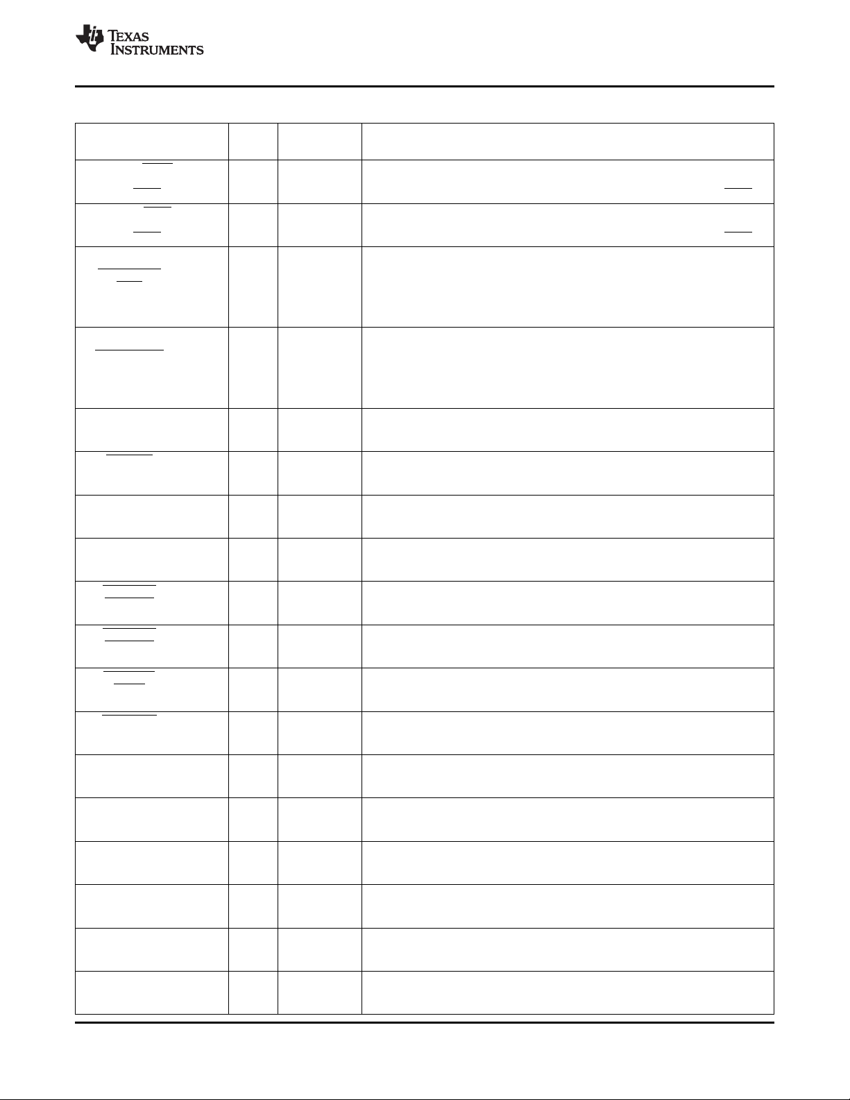
TMS320DM6467
www.ti.com
SPRS403G–DECEMBER 2007–REVISED OCTOBER 2010
Table 3-9. Asynchronous External Memory Interface (EMIFA) Terminal Functions (continued)
SIGNAL
NAME NO.
PCI_RSV4/DIOW/ This pin is multiplexed between PCI, ATA, GPIO, and EMIFA.
GP[20]/EM_WAIT4/ A11 I/O/Z In EMIFA mode, this pin is wait state extension input 4 EM_WAIT4 (I).
(RDY4/BSY4) When used for EMIFA (NAND), this pin is the ready/busy 4 input (RDY4/BSY4).
PCI_RSV3/DIOR/ This pin is multiplexed between PCI, ATA, GPIO, and EMIFA.
GP[19]/EM_WAIT5/ E10 I/O/Z For EMIFA, this pin is wait state extension input 5 EM_WAIT5 (I).
(RDY5/BSY5) When used for EMIFA (NAND), this pin is the ready/busy 5 input (RDY5/BSY5).
PCI_FRAME/
HINT/ D6 I/O/Z
EM_BA[0]
PCI_DEVSEL/
HCNTL1/ B3 I/O/Z
EM_BA[1]
PCI_RSV2/INTRQ/ IPD
GP[18]/EM_RSV0 DV
B10 I/O/Z In EMIFA mode, this pin is reserved.
PCI_RST/ This pin is multiplexed between PCI, ATA, GPIO, and EMIFA.
DA2/ C10 I/O/Z In EMIFA mode, this pin is address bit 22 output EM_A[22] (O/Z).
GP[13]/EM_A[22] This signal is not available when ATA is enabled (i.e., EMIF NAND Flash mode).
PCI_RSV0/DA1/ IPD
GP[16]/EM_A[21] DV
PCI_RSV1/DA0/ IPD
GP[17]/EM_A[20] DV
A9 I/O/Z In EMIFA mode, this pin is address bit 21 output EM_A[21] (O/Z).
E9 I/O/Z In EMIFA mode, this pin is address bit 20 output EM_A[20] (O/Z).
PCI_CBE1/ This pin is multiplexed between PCI, ATA, GPIO, and EMIFA.
ATA_CS1/ C2 I/O/Z In EMIFA mode, this pin is address bit 19 output EM_A[19] (O/Z).
GP[32]/EM_A[19] This signal is not available when ATA is enabled (i.e., EMIF NAND Flash mode).
PCI_CBE0/ This pin is multiplexed between PCI, ATA, GPIO, and EMIFA.
ATA_CS0/ F4 I/O/Z In EMIFA mode, this pin is address bit 18 output EM_A[18] (O/Z).
GP[33]/EM_A[18] This signal is not available when ATA is enabled (i.e., EMIF NAND Flash mode).
PCI_IRDY/ This pin is multiplexed between PCI, HPI, and EMIFA.
HRDY/ A3 I/O/Z In EMIFA mode, this pin is address bit 17 output EM_A[17] (O/Z).
EM_A[17]/(CLE) When used for EMIFA (NAND), this pin is Command Latch Enable output (CLE).
PCI_TRDY/ This pin is multiplexed between PCI, HPI, and EMIFA.
HHWIL/ E6 I/O/Z For EMIFA, this pin is address bit 16 output EM_A[16] (O/Z).
EM_A[16]/(ALE) When used for EMIFA (NAND), this pin is Address Latch Enable output (ALE).
PCI_AD31/ This pin is multiplexed between PCI, ATA, HPI, and EMIFA.
DD15/ A8 I/O/Z For EMIFA, this pin is address bit 15 output EM_A[15] (O/Z).
HD31/EM_A[15] This signal is not available when ATA is enabled (i.e., EMIF NAND Flash mode).
PCI_AD30/ This pin is multiplexed between PCI, ATA, HPI, and EMIFA.
DD14/ C9 I/O/Z For EMIFA, this pin is address bit 14 output EM_A[14] (O/Z).
HD30/EM_A[14] This signal is not available when ATA is enabled (i.e., EMIF NAND Flash mode).
PCI_AD29/ This pin is multiplexed between PCI, ATA, HPI, and EMIFA.
DD13/ B8 I/O/Z For EMIFA, this pin is address bit 13 output EM_A[13] (O/Z).
HD29/EM_A[13] This signal is not available when ATA is enabled (i.e., EMIF NAND Flash mode).
PCI_AD28/ This pin is multiplexed between PCI, ATA, HPI, and EMIFA.
DD12/ D9 I/O/Z For EMIFA, this pin is address bit 12 output EM_A[12] (O/Z).
HD28/EM_A[12] This signal is not available when ATA is enabled (i.e., EMIF NAND Flash mode).
PCI_AD27/ This pin is multiplexed between PCI, ATA, HPI, and EMIFA.
DD11/ A6 I/O/Z For EMIFA, this pin is address bit 11 output EM_A[11] (O/Z).
HD27/EM_A[11] This signal is not available when ATA is enabled (i.e., EMIF NAND Flash mode).
PCI_AD26/ This pin is multiplexed between PCI, ATA, HPI, and EMIFA.
DD10/ C8 I/O/Z For EMIFA, this pin is address bit 10 output EM_A[10] (O/Z).
HD26/EM_A[10] This signal is not available when ATA is enabled (i.e., EMIF NAND Flash mode).
TYPE
(1)
(2) (3)
OTHER
DESCRIPTION
IPU
DV
DD33
IPU
DV
DD33
This pin is multiplexed between PCI, HPI, and EMIFA.
For EMIFA, this is the Bank Address 0 output EM_BA[0] (O/Z).
IPU When connected to a 16-bit asynchronous memory, this pin has the same
DV
DD33
function as EMIF address pin 22 (EM_A[22]).
When connected to an 8-bit asynchronous memory, this pin is the lowest order bit
of the byte address.
This pin is multiplexed between PCI, HPI, and EMIFA.
For EMIFA, this is the Bank Address 1 output EM_BA[1] (O/Z).
IPU When connected to a 16 bit asynchronous memory this pin is the lowest order bit
DV
DD33
of the 16-bit word address.
When connected to an 8-bit asynchronous memory, this pin is the second bit of
the address.
This pin is multiplexed between PCI, ATA, GPIO, and EMIFA.
DD33
This signal is not available when ATA is enabled (i.e., EMIF NAND Flash mode).
IPD
DV
DD33
This pin is multiplexed between PCI, ATA, GPIO, and EMIFA.
DD33
This signal is not available when ATA is enabled (i.e., EMIF NAND Flash mode).
This pin is multiplexed between PCI ATA, GPIO, and EMIFA.
DD33
This signal is not available when ATA is enabled (i.e., EMIF NAND Flash mode).
IPU
DV
DD33
IPU
DV
DD33
IPU
DV
DD33
IPU
DV
DD33
IPD
DV
DD33
IPD
DV
DD33
IPD
DV
DD33
IPD
DV
DD33
IPD
DV
DD33
IPD
DV
DD33
Copyright © 2007–2010, Texas Instruments Incorporated Device Overview 37
Submit Documentation Feedback
Product Folder Link(s): TMS320DM6467
Page 38

TMS320DM6467
SPRS403G–DECEMBER 2007–REVISED OCTOBER 2010
www.ti.com
Table 3-9. Asynchronous External Memory Interface (EMIFA) Terminal Functions (continued)
SIGNAL
NAME NO.
PCI_AD25/ This pin is multiplexed between PCI, ATA, HPI, and EMIFA.
DD9/ B6 I/O/Z For EMIFA, this pin is address bit 9 output EM_A[9] (O/Z).
HD25/EM_A[9] This signal is not available when ATA is enabled (i.e., EMIF NAND Flash mode).
PCI_AD24/ This pin is multiplexed between PCI, ATA, HPI, and EMIFA.
DD8/ D8 I/O/Z For EMIFA, this pin is address bit 8 output EM_A[8] (O/Z).
HD24/EM_A[8] This signal is not available when ATA is enabled (i.e., EMIF NAND Flash mode).
PCI_AD23/ This pin is multiplexed between PCI, ATA, HPI, and EMIFA.
DD7/ B5 I/O/Z For EMIFA, this pin is address bit 7 output EM_A[7] (O/Z).
HD23/EM_A[7] This signal is not available when ATA is enabled (i.e., EMIF NAND Flash mode).
PCI_AD22/ This pin is multiplexed between PCI, ATA, HPI, and EMIFA.
DD6/ C7 I/O/Z For EMIFA, this pin is address bit 6 output EM_A[6] (O/Z).
HD22/EM_A[6] This signal is not available when ATA is enabled (i.e., EMIF NAND Flash mode).
PCI_AD21/ This pin is multiplexed between PCI, ATA, HPI, and EMIFA.
DD5/ C5 I/O/Z For EMIFA, this pin is address bit 5 output EM_A[5] (O/Z).
HD21/EM_A[5] This signal is not available when ATA is enabled (i.e., EMIF NAND Flash mode).
PCI_AD20/ This pin is multiplexed between PCI, ATA, HPI, and EMIFA.
DD4/ D7 I/O/Z For EMIFA, this pin is address bit 4 output EM_A[4] (O/Z).
HD20/EM_A[4] This signal is not available when ATA is enabled (i.e., EMIF NAND Flash mode).
PCI_AD19/ This pin is multiplexed between PCI, ATA, HPI, and EMIFA.
DD3/ A4 I/O/Z For EMIFA, this pin is address bit 3 output EM_A[3] (O/Z).
HD19/EM_A[3] This signal is not available when ATA is enabled (i.e., EMIF NAND Flash mode).
PCI_AD18/ This pin is multiplexed between PCI, ATA, HPI, and EMIFA.
DD2/ E7 I/O/Z For EMIFA, this pin is address bit 2 output EM_A[2] (O/Z).
HD18/EM_A[2] This signal is not available when ATA is enabled (i.e., EMIF NAND Flash mode).
PCI_AD17/ This pin is multiplexed between PCI, ATA, HPI, and EMIFA.
DD1/ B4 I/O/Z For EMIFA, this pin is address bit 1 output EM_A[1] (O/Z).
HD17/EM_A[1] This signal is not available when ATA is enabled (i.e., EMIF NAND Flash mode).
PCI_AD16/
DD0/ C6 I/O/Z
HD16/EM_A[0]
TYPE
(1)
(2) (3)
OTHER
IPD
DV
DD33
IPD
DV
DD33
IPD
DV
DD33
IPD
DV
DD33
IPD
DV
DD33
IPD
DV
DD33
IPD
DV
DD33
IPD
DV
DD33
IPD
DV
DD33
This pin is multiplexed between PCI, ATA, HPI, and EMIFA.
For EMIFA, this pin is address bit 0 output EM_A[0] (O/Z), which is the least
IPD significant bit on a 32-bit word address.
DV
DD33
When connected to a 16-bit asynchronous memory, this pin is the second bit of
the address.
For an 8-bit asynchronous memory, this pin is the third bit of the address.
DESCRIPTION
38 Device Overview Copyright © 2007–2010, Texas Instruments Incorporated
Submit Documentation Feedback
Product Folder Link(s): TMS320DM6467
Page 39

TMS320DM6467
www.ti.com
SPRS403G–DECEMBER 2007–REVISED OCTOBER 2010
Table 3-9. Asynchronous External Memory Interface (EMIFA) Terminal Functions (continued)
SIGNAL
NAME NO.
PCI_AD15/ IPD
HD15/EM_D15 DV
PCI_AD14/ IPD
HD14 /EM_D14 DV
PCI_AD13/ IPD
HD13/EM_D13 DV
PCI_AD12/ IPD
HD12/EM_D12 DV
PCI_AD11/ IPD
HD11/EM_D11 DV
PCI_AD10/ IPD
HD10/EM_D10 DV
PCI_AD9/ IPD
HD9/EM_D9 DV
PCI_AD8/ IPD
HD8/EM_D8 DV
PCI_AD7/ IPD
HD7/EM_D7 DV
PCI_AD6/ IPD
HD6/EM_D6 DV
PCI_AD5/ IPD
HD5/EM_D5 DV
PCI_AD4/ IPD
HD4/EM_D4 DV
PCI_AD3/ IPD
HD3/EM_D3 DV
PCI_AD2/ IPD
HD2/EM_D2 DV
PCI_AD1/ IPD
HD1/EM_D1 DV
PCI_AD0/ IPD
HD0/EM_D0 DV
E5 I/O/Z
C1 I/O/Z
E4 I/O/Z
D3 I/O/Z
E3 I/O/Z
D2 I/O/Z
F5 I/O/Z
D1 I/O/Z
E2 I/O/Z
F3 I/O/Z
E1 I/O/Z
G5 I/O/Z
F2 I/O/Z
G4 I/O/Z
F1 I/O/Z
G3 I/O/Z
PCI_IRDY/ This pin is multiplexed between PCI, HPI, and EMIFA.
HRDY/ A3 I/O/Z In EMIFA mode, this pin is address bit 17 output EM_A[17] (O/Z).
EM_A[17]/(CLE) When used for EMIFA (NAND), this pin is Command Latch Enable output (CLE).
PCI_TRDY/ This pin is multiplexed between PCI, HPI, and EMIFA.
HHWIL/ E6 I/O/Z For EMIFA, this pin is address bit 16 output EM_A[16] (O/Z).
EM_A[16]/(ALE) When used for EMIFA (NAND), this pin is Address Latch Enable output (ALE).
PCI_INTA/ This pin is multiplexed between PCI and EMIFA.
EM_WAIT2/ C11 I/O/Z In EMIFA mode, this pin is wait state extension input 2 EM_WAIT2 (I).
(RDY2/BSY2) When used for EMIFA (NAND), this pin is the ready/busy 2 input (RDY2/BSY2).
IORDY/ This pin is multiplexed between ATA, GPIO, and EMIFA.
GP[21]/EM_WAIT3/ D11 I/O/Z In EMIFA mode, this pin is wait state extension input 3 EM_WAIT3 (I).
(RDY3/BSY3) When used for EMIFA (NAND), this pin is the ready/busy 3 input (RDY3/BSY3).
DIOW/ This pin is multiplexed between ATA, GPIO, and EMIFA.
GP[20]/EM_WAIT4/ A11 I/O/Z In EMIFA mode, this pin is wait state extension input 4 EM_WAIT4 (I).
(RDY4/BSY4) When used for EMIFA (NAND), this pin is the ready/busy 4 input (RDY4/BSY4).
DIOR/ This pin is multiplexed between ATA, GPIO, and EMIFA.
GP[19]/EM_WAIT5/ E10 I/O/Z For EMIFA, this pin is wait state extension input 5 EM_WAIT5 (I).
(RDY5/BSY5) When used for EMIFA (NAND), this pin is the ready/busy 5 input (RDY5/BSY5).
PCI_SERR/
HDS1/ B2 I/O/Z
EM_OE
TYPE
(1)
(2) (3)
OTHER
DD33
DD33
DD33
DD33
DD33
DD33
DD33
DESCRIPTION
These pins are multiplexed between PCI, HPI, and EMIFA.
DD33
For EMIFA mode, these pins are the 16-bit bidirectional data bus (EM_D[15:0])
[I/O/Z].
When EMIFA is configured for an 8-bit asynchronous memory, only EM_D[7:0]
DD33
DD33
DD33
DD33
DD33
DD33
DD33
DD33
pins are used.
EMIFA FUNCTIONAL PINS: NAND
IPU
DV
DD33
IPU
DV
DD33
IPU
DV
DD33
IPU
DV
DD33
IPU
DV
DD33
IPU
DV
DD33
IPU This pin is multiplexed between PCI, HPI, and EMIFA.
DV
DD33
In EMIFA mode, this pin is the output enable output EM_OE (O/Z).
Copyright © 2007–2010, Texas Instruments Incorporated Device Overview 39
Submit Documentation Feedback
Product Folder Link(s): TMS320DM6467
Page 40

TMS320DM6467
SPRS403G–DECEMBER 2007–REVISED OCTOBER 2010
Table 3-9. Asynchronous External Memory Interface (EMIFA) Terminal Functions (continued)
SIGNAL
NAME NO.
PCI_STOP/
HCNTL0/ D5 I/O/Z
EM_WE
PCI_CBE2/
HDS2/ C4 I/O/Z
EM_CS2
PCI_CBE3/ This pin is multiplexed between PCI, HPI, and EMIFA.
HR/W A5 I/O/Z In EMIFA mode, this pin is Chip Select 3 output EM_CS3 (O/Z). Asynchronous
EM_CS3 memories (i.e., NOR Flash).
PCI_AD15/ IPD
HD15/EM_D15 DV
PCI_AD14/ IPD
HD14 /EM_D14 DV
PCI_AD13/ IPD
HD13/EM_D13 DV
PCI_AD12/ IPD
HD12/EM_D12 DV
PCI_AD11/ IPD
HD11/EM_D11 DV
PCI_AD10/ IPD
HD10/EM_D10 DV
PCI_AD9/ IPD
HD9/EM_D9 DV
PCI_AD8/ IPD
HD8/EM_D8 DV
PCI_AD7/ IPD
HD7/EM_D7 DV
PCI_AD6/ IPD
HD6/EM_D6 DV
PCI_AD5/ IPD
HD5/EM_D5 DV
PCI_AD4/ IPD
HD4/EM_D4 DV
PCI_AD3/ IPD
HD3/EM_D3 DV
PCI_AD2/ IPD
HD2/EM_D2 DV
PCI_AD1/ IPD
HD1/EM_D1 DV
PCI_AD0/ IPD
HD0/EM_D0 DV
E5 I/O/Z
C1 I/O/Z
E4 I/O/Z
D3 I/O/Z
E3 I/O/Z
D2 I/O/Z
F5 I/O/Z
D1 I/O/Z
E2 I/O/Z
F3 I/O/Z
E1 I/O/Z
G5 I/O/Z
F2 I/O/Z
G4 I/O/Z
F1 I/O/Z
G3 I/O/Z
TYPE
(1)
(2) (3)
OTHER
DESCRIPTION
IPU This pin is multiplexed between PCI, HPI, and EMIFA.
DV
DD33
In EMIFA mode, this pin is the write enable output EM_WE (O/Z).
This pin is multiplexed between PCI, HPI, and EMIFA.
IPU In EMIFA mode, this pin is Chip Select 2 output EM_CS2 (O/Z). This is the chip
DV
DD33
select used for EMIFA boot modes. Asynchronous memories (i.e., NOR Flash) or
NAND flash.
IPU
DV
DD33
DD33
DD33
DD33
DD33
DD33
DD33
DD33
These pins are multiplexed between PCI, HPI, and EMIFA.
DD33
For EMIFA mode, these pins are the 16-bit bidirectional data bus (EM_D[15:0])
[I/O/Z].
When EMIFA is configured for an 8-bit asynchronous memory, only EM_D[7:0]
DD33
DD33
DD33
DD33
DD33
DD33
DD33
DD33
pins are used.
www.ti.com
40 Device Overview Copyright © 2007–2010, Texas Instruments Incorporated
Submit Documentation Feedback
Product Folder Link(s): TMS320DM6467
Page 41

TMS320DM6467
www.ti.com
3.7.6 DDR2 Memory Controller
Table 3-10. DDR2 Memory Controller Terminal Functions
SIGNAL
NAME NO.
DDR_CLK M23 O/Z DV
DDR_CLK L23 O/Z DV
DDR_CKE M20 O/Z DV
DDR_CS J20 O/Z DV
DDR_WE L20 O/Z DV
DDR_RAS K19 O/Z DV
DDR_CAS L21 O/Z DV
DDR_DQM[3] V20 O/Z DV
DDR_DQM[2] Y23 O/Z DV
DDR_DQM[1] F22 O/Z DV
DDR_DQM[0] F20 O/Z DV
DDR_DQS[3] U20 I/O/Z DV
DDR_DQS[2] V22 I/O/Z DV
DDR_DQS[1] D22 I/O/Z DV
DDR_DQS[0] D21 I/O/Z DV
DDR_DQS[3] V21 I/O/Z DV
DDR_DQS[2] W23 I/O/Z DV
DDR_DQS[1] D23 I/O/Z DV
DDR_DQS[0] E20 I/O/Z DV
DDR_ODT0 K20 O/Z DV
DDR_BA[2] P19
DDR_BA[1] M21 O/Z DV
DDR_BA[0] N19
DDR_A[14] N23
DDR_A[13] H21
DDR_A[12] P20
DDR_A[11] K23
DDR_A[10] T23
DDR_A[9] N22
DDR_A[8] J23
DDR_A[7] N20 O/Z DV
DDR_A[6] M22
DDR_A[5] N21
DDR_A[4] J22
DDR_A[3] R22
DDR_A[2] L22
DDR_A[1] R23
DDR_A[0] H23
TYPE
(1)
OTHER
(2) (3)
DDR2
DDR2
DDR2
DDR2
DDR2
DDR2
DDR2
DDR2
DDR2
DDR2
DDR2
DDR2
DDR2
DDR2
DDR2
DDR2
DDR2
DDR2
DDR2
DDR2
DDR2
DDR2
SPRS403G–DECEMBER 2007–REVISED OCTOBER 2010
DESCRIPTION
DDR2 Memory Controller
DDR2 Clock
DDR2 Differential clock
DDR2 Clock Enable
DDR2 Active low chip select
DDR2 Active low Write enable
DDR2 Row Access Signal output
DDR2 Column Access Signal output
DDR2 Data mask outputs
DDR_DQM[3]: For upper byte data bus DDR_D[31:24]
DDR_DQM[2]: For DDR_D[23:16]
DDR_DQM[1]: For DDR_D[15:8]
DDR_DQM[0]: For lower byte DDR_D[7:0]
Data strobe input/outputs for each byte of the 32-bit data bus. They are outputs to
the DDR2 memory when writing and inputs when reading. They are used to
synchronize the data transfers.
DDR_DQS[3] : For upper byte DDR_D[31:24]
DDR_DQS[2]: For DDR_D[23:16]
DDR_DQS[1]: For DDR_D[15:8]
DDR_DQS[0]: For bottom byte DDR_D[7:0]
Complimentary data strobe input/outputs for each byte of the 32-bit data bus. They
are outputs to the DDR2 memory when writing and inputs when reading. They are
used to synchronize the data transfers.
DDR_DQS[3] : For upper byte DDR_D[31:24]
DDR_DQS[2]: For DDR_D[23:16]
DDR_DQS[1]: For DDR_D[15:8]
DDR_DQS[0]: For bottom byte DDR_D[7:0]
DDR2 on-die termination control
Bank address outputs (BA[2:0]).
DDR2 address bus
(1) I = Input, O = Output, Z = High impedance, S = Supply voltage, GND = Ground, A = Analog signal
(2) Specifies the operating I/O supply voltage for each signal
(3) For more information, see the Recommended Operating Conditions table
Copyright © 2007–2010, Texas Instruments Incorporated Device Overview 41
Submit Documentation Feedback
Product Folder Link(s): TMS320DM6467
Page 42

TMS320DM6467
SPRS403G–DECEMBER 2007–REVISED OCTOBER 2010
Table 3-10. DDR2 Memory Controller Terminal Functions (continued)
SIGNAL
NAME NO.
DDR_D[31] Y20
DDR_D[30] W20
DDR_D[29] Y21
DDR_D[28] AA21
DDR_D[27] U21
DDR_D[26] T21
DDR_D[25] R20
DDR_D[24] T20
DDR_D[23] AB22
DDR_D[22] Y22
DDR_D[21] AA22
DDR_D[20] AA23
DDR_D[19] V23
DDR_D[18] U23
DDR_D[17] T22
DDR_D[16] U22
DDR_D[15] H22
DDR_D[14] G23
DDR_D[13] G22
DDR_D[12] F23
DDR_D[11] E23
DDR_D[10] C22
DDR_D[9] B22
DDR_D[8] C23
DDR_D[7] H20
DDR_D[6] G21
DDR_D[5] F21
DDR_D[4] G20
DDR_D[3] B21
DDR_D[2] C20
DDR_D[1] D20
DDR_D[0] C21
DDR_DQGATE0 J19 O/Z DV
DDR_DQGATE1 J21 I DV
DDR_DQGATE2 R19 O/Z DV
DDR_DQGATE3 R21 I DV
DDR_VREF P23 S
DDR_ZP L19 O
DDR_ZN M19 O
(4) For more information, see the Recommended Operating Conditions table
(1)
TYPE
OTHER
I/O/Z DV
(2) (3)
DDR2
DDR2
DDR2
DDR2
DDR2
(4)
(4)
(4)
DDR2 data bus can be configured as 32 bits wide or 16 bits wide.
DDR2 strobe gate signal for lower-half data bus
DDR2 strobe gate signal return for lower-half data bus
DDR2 strobe gate signal for upper-half data bus
DDR2 strobe gate signal return for upper-half data bus
Reference voltage input for the SSTL_18 IO buffers.
Impedance control for DDR2 outputs. This must be connected via a 50-Ω (±5%
tolerance) resistor to VSS.
Impedance control for DDR2 outputs. This must be connected via a 50-Ω (±5%
tolerance) resistor to DV
DDR2
www.ti.com
DESCRIPTION
.
42 Device Overview Copyright © 2007–2010, Texas Instruments Incorporated
Submit Documentation Feedback
Product Folder Link(s): TMS320DM6467
Page 43

TMS320DM6467
www.ti.com
SPRS403G–DECEMBER 2007–REVISED OCTOBER 2010
3.7.7 Peripheral Component Interconnect (PCI)
Table 3-11. Peripheral Component Interconnect (PCI) Terminal Functions
SIGNAL
NAME NO.
Note: When PCI boot mode is not used, for proper device operation out of reset PCIEN must be "0".
The PCI pin functions are enabled when PCIEN = 1 (PCI mode). This can be done via an external PU on the PCIEN pin (AC6) or by setting
the PCIEN bit (bit 2) in the PINMUX0 register to a "1" after device reset. For more details on the PCIEN pin, see Table 3-5, Boot Terminal
Functions.
In PCI mode (PCIEN = 1), the internal pullups/pulldowns (IPUs/IPDs) are disabled on all PCI pins and it is recommended to have external
pullup resistors on the PCI_RSV[5:0] pins. For more detailed information on external pullup/pulldown resistors, see Section 4.8.1,
Pullup/Pulldown Resistors.
Also in PCI mode (PCIEN = 1), the internal pulldowns (IPDs) are disabled on the GP[5:7] pins. It is recommended to have external pullup
resistors on the GP[5] pin when PCIEN = 1 and on GP[6:7] pins when PCIEN = 1 and VADJEN = 0.
PCI_CLK/GP[10] A10 I/O/Z
PCI_RST /DA2/ [IPD] This pin is multiplexed between the PCI, ATA, GPIO, and EMIFA.
GP[13]/EM_A[22] DV
PCI_IDSEL/ [IPU]
HDDIR/EM_R/W DV
PCI_DEVSEL / [IPU] This pin is multiplexed between PCI, HPI, and EMIFA.
HCNTL1/EM_BA[1] DV
PCI_FRAME / [IPU] This pin is multiplexed between PCI, HPI, and EMIFA.
HINT/EM_BA[0] DV
PCI_IRDY /HRDY/ [IPU] This pin is multiplexed between PCI, HPI, and EMIFA.
EM_A[17]/(CLE) DV
PCI_ TRDY /HHWIL/ IPU This pin is multiplexed between PCI, HPI, and EMIFA.
EM_A[16]/(ALE) DV
PCI_STOP / [IPU] This pin is multiplexed between PCI, HPI, and EMIFA.
HCNTL0/EM_WE DV
PCI_SERR / [IPU] This pin is multiplexed between PCI, HPI, and EMIFA.
HDS1/EM_OE DV
PCI_PERR / [IPU] This pin is multiplexed between PCI, HPI, and EMIFA.
HCS/EM_DQM1 DV
PCI_PAR/ [IPU] This pin is multiplexed between PCI, HPI, and EMIFA.
HAS/EM_DQM0 DV
C10 I/O/Z
E8 I/O/Z In PCI mode, this pin is the PCI initialization device select, PCI_IDSEL
B3 I/O/Z
D6 I/O/Z
A3 I/O/Z
E6 I/O/Z
D5 I/O/Z
B2 I/O/Z
C3 I/O/Z
D4 I/O/Z
PCI_INTA /
EM_WAIT2/ C11 I/O/Z
(RDY2/BSY2)
PCI_REQ /
DMARQ/ B9 I/O/Z
GP[11]/EM_CS5
PCI_GNT /
DMACK/ D10 I/O/Z
GP[12]/EM_CS4
PCI_CBE3 / [IPU]
HR/W/EM_CS3 DV
PCI_CBE2 / [IPU]
HDS2/EM_CS2 DV
A5 I/O/Z In PCI mode, this pin is the PCI command/byte enable 3, PCI_CBE3
C4 I/O/Z In PCI mode, this pin is the PCI command/byte enable 2, PCI_CBE2
TYPE
(1)
OTHER
(2) (3)
DESCRIPTION
PCI
[IPU] This pin is multiplexed between PCI and GPIO.
DV
DD33
DD33
In PCI mode, this pin is the PCI clock input PCI_CLK (I).
In PCI mode, this pin is PCI reset PCI_RST (I).
This pin is multiplexed between PCI, ATA, and EMIFA.
DD33
DD33
DD33
DD33
DD33
DD33
DD33
DD33
DD33
(I).
In PCI mode, this pin is the PCI device select, PCI_DEVSEL (I/O/Z).
In PCI mode, this pin is the PCI cycle frame, PCI_FRAME (I/O/Z).
In PCI mode, this pin is the PCI initiator ready, PCI_IRDY (I/O/Z).
In PCI mode, this pin is the PCI target ready, PCI_ TRDY (I/O/Z).
In PCI mode, this pin is the PCI stop, PCI_STOP (I/O/Z).
In PCI mode, this pin is the PCI system error, PCI_SERR (I/O/Z).
In PCI mode, this pin is the PCI parity error, PCI_PERR (I/O/Z).
In PCI mode, this pin is the PCI parity, PCI_PAR (I/O/Z).
[IPU] This pin is multiplexed between the PCI and EMIFA.
DV
DD33
In PCI mode, this pin is the PCI interrupt A, PCI_INTA (O/Z).
[IPU] This pin is multiplexed between the PCI, ATA, GPIO, and EMIFA.
DV
DD33
In PCI mode, this pin is the PCI bus request, PCI_REQ (O/Z).
[IPU] This pin is multiplexed between the PCI, ATA, GPIO, and EMIFA.
DV
DD33
In PCI mode, this pin is PCI bus grant, PCI_GNT (I).
This pin is multiplexed between PCI, HPI, and EMIFA.
DD33
(I/O/Z).
This pin is multiplexed between PCI, HPI, and EMIFA.
DD33
(I/O/Z).
(1) I = Input, O = Output, Z = High impedance, S = Supply voltage, GND = Ground, A = Analog signal
(2) IPD = Internal pulldown, IPU = Internal pullup. For more detailed information on pullup/pulldown resistors and situations where external
pullup/pulldown resistors are required, see Section 4.8.1, Pullup/Pulldown Resistors.
(3) Specifies the operating I/O supply voltage for each signal
Copyright © 2007–2010, Texas Instruments Incorporated Device Overview 43
Submit Documentation Feedback
Product Folder Link(s): TMS320DM6467
Page 44

TMS320DM6467
SPRS403G–DECEMBER 2007–REVISED OCTOBER 2010
Table 3-11. Peripheral Component Interconnect (PCI) Terminal Functions (continued)
SIGNAL
NAME NO.
PCI_CBE1 / This pin is multiplexed between PCI, ATA, GPIO, and EMIFA.
ATA_CS1/ C2 I/O/Z In PCI mode, this pin is the PCI command/byte enable 1 PCI_CBE1
GP[32]/EM_A[19] (I/O/Z).
PCI_CBE0 / This pin is multiplexed between PCI, ATA, GPIO, and EMIFA.
ATA_CS0/ F4 I/O/Z In PCI mode, this pin is the PCI command/byte enable 0 PCI_CBE0
GP[33]/EM_A[18] (I/O/Z).
TYPE
(1)
OTHER
(2) (3)
DESCRIPTION
[IPU]
DV
DD33
[IPU]
DV
DD33
www.ti.com
44 Device Overview Copyright © 2007–2010, Texas Instruments Incorporated
Submit Documentation Feedback
Product Folder Link(s): TMS320DM6467
Page 45
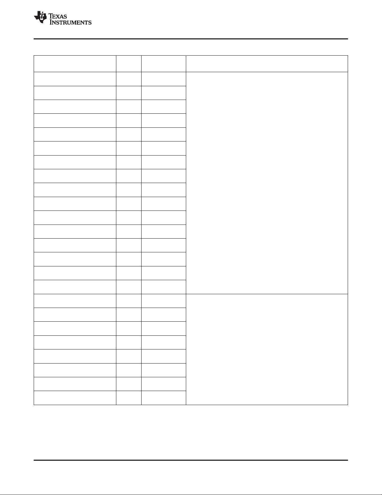
TMS320DM6467
www.ti.com
Table 3-11. Peripheral Component Interconnect (PCI) Terminal Functions (continued)
SIGNAL
NAME NO.
PCI_AD31/DD15/ [IPD]
HD31/EM_A[15] DV
PCI_AD30/DD14/ [IPD]
HD30/EM_A[14] DV
PCI_AD29/DD13/ [IPD]
HD29/EM_A[13] DV
PCI_AD28/DD12/ [IPD]
HD28/EM_A[12] DV
PCI_AD27/DD11/ [IPD]
HD27/EM_A[11] DV
PCI_AD26/DD10/ [IPD]
HD26/EM_A[10] DV
PCI_AD25/DD9/ [IPD]
HD25/EM_A[9] DV
PCI_AD24/DD8/ [IPD]
HD24/EM_A[8] DV
PCI_AD23/DD7/ [IPD]
HD23/EM_A[7] DV
PCI_AD22/DD6/ [IPD]
HD22/EM_A[6] DV
PCI_AD21/DD5/ [IPD]
HD21/EM_A[5] DV
PCI_AD20/DD4/ [IPD]
HD20/EM_A[4] DV
PCI_AD19/DD3/ [IPD]
HD19/EM_A[3] DV
PCI_AD18/DD2/ [IPU]
HD18/EM_A[2] DV
PCI_AD17/DD1/ [IPD]
HD17/EM_A[1] DV
PCI_AD16/DD0/ [IPD]
HD16/EM_A[0] DV
PCI_AD15/ [IPD]
HD15/EM_D15 DV
PCI_AD14/ [IPD]
HD14/EM_D14 DV
PCI_AD13/ [IPD]
HD13/EM_D13 DV
PCI_AD12/ [IPD]
HD12/EM_D12 DV
PCI_AD11/ [IPD]
HD11/EM_D11 DV
PCI_AD10/ [IPD]
HD10/EM_D10 DV
PCI_AD9/ [IPU]
HD9/EM_D9 DV
PCI_AD8/ [IPD]
HD8/EM_D8 DV
A8 I/O/Z
C9 I/O/Z
B8 I/O/Z
D9 I/O/Z
A6 I/O/Z
C8 I/O/Z
B6 I/O/Z
D8 I/O/Z
B5 I/O/Z
C7 I/O/Z
C5 I/O/Z
D7 I/O/Z
A4 I/O/Z
E7 I/O/Z
B4 I/O/Z
C6 I/O/Z
E5 I/O/Z
C1 I/O/Z
E4 I/O/Z
D3 I/O/Z
E3 I/O/Z
D2 I/O/Z
F5 I/O/Z
D1 I/O/Z
TYPE
(1)
OTHER
DD33
DD33
DD33
DD33
DD33
DD33
DD33
DD33
DD33
DD33
DD33
DD33
DD33
DD33
DD33
DD33
DD33
DD33
DD33
DD33
DD33
DD33
DD33
DD33
(2) (3)
SPRS403G–DECEMBER 2007–REVISED OCTOBER 2010
DESCRIPTION
These pins are multiplexed between PCI, ATA, HPI, and EMIFA.
In PCI mode, these pins are the PCI address/data bus, PCI_AD[31:16]
(I/O/Z).
These pins are multiplexed between PCI, HPI, and EMIFA.
For PCI, these pins are PCI data/address bus, PCI_AD [15:0] (I/O/Z).
Copyright © 2007–2010, Texas Instruments Incorporated Device Overview 45
Submit Documentation Feedback
Product Folder Link(s): TMS320DM6467
Page 46

TMS320DM6467
SPRS403G–DECEMBER 2007–REVISED OCTOBER 2010
Table 3-11. Peripheral Component Interconnect (PCI) Terminal Functions (continued)
SIGNAL
NAME NO.
PCI_AD7/ [IPD]
HD7/EM_D7 DV
PCI_AD6/ [IPD]
HD6/EM_D6 DV
PCI_AD5/ [IPD]
HD5/EM_D5 DV
PCI_AD4/ [IPD]
HD4/EM_D4 DV
PCI_AD3/ [IPD]
HD3/EM_D3 DV
PCI_AD2/ [IPD]
HD2/EM_D2 DV
PCI_AD1/ [IPD]
HD1/EM_D1 DV
PCI_AD0/ [IPD]
HD0/EM_D0 DV
PCI_RSV0/DA1/ [IPD]
GP[16]/EM_A[21] DV
PCI_RSV1/DA0/ [IPD]
GP[17]/EM_A[20] DV
PCI_RSV2/INTRQ/ [IPD]
GP[18]/EM_RSV 0 DV
E2 I/O/Z
F3 I/O/Z
E1 I/O/Z
G5 I/O/Z
F2 I/O/Z
G4 I/O/Z
F1 I/O/Z
G3 I/O/Z
A9 I/O/Z PCI reserved for future enhancements (I)
E9 I/O/Z PCI reserved for future enhancements (O/Z)
B10 I/O/Z PCI reserved for future enhancements (I)
PCI_RSV3/DIOR/
GP[19]/ E10 I/O/Z PCI reserved for future enhancements (O/Z)
EM_WAIT5
PCI_RSV4/DIOW/
GP[20]/ A11 I/O/Z PCI reserved for future enhancements (I/O/Z)
EM_WAIT4
PCI_RSV5/IORDY/
GP[21]/ D11 I/O/Z PCI reserved for future enhancements (I/O/Z)
EM_WAIT3
(1) In PCI mode (PCIEN = 1), it is recommended to have an external pullup resistor on this pin.
TYPE
(1)
OTHER
DD33
DD33
DD33
DD33
(2) (3)
These pins are multiplexed between PCI, HPI, and EMIFA.
For PCI, these pins are PCI data/address bus [15:0] (I/O/Z)
DD33
DD33
DD33
DD33
DD33
DD33
DD33
[IPU]
DV
DD33
[IPU]
DV
DD33
[IPU]
DV
DD33
www.ti.com
DESCRIPTION
(1)
(1)
(1)
(1)
(1)
(1)
46 Device Overview Copyright © 2007–2010, Texas Instruments Incorporated
Submit Documentation Feedback
Product Folder Link(s): TMS320DM6467
Page 47

TMS320DM6467
www.ti.com
SPRS403G–DECEMBER 2007–REVISED OCTOBER 2010
3.7.8 EMAC [G]MII and MDIO
Table 3-12. EMAC [G]MII and MDIO Terminal Functions
SIGNAL
NAME NO.
RFTCLK H1 I Gigabit (GMII) reference transmit clock (125 MHz)
GMTCLK P2 O/Z GMII source asynchronous transmit clock
MTCLK R1 I [G]MII transmit clock input
MTXD7 P1
MTXD6 N4
MTXD5 N3
MTXD4 N2
MTXD3 N1
MTXD2 M4
MTXD1 M1
MTXD0 L1
MTXEN L2 O/Z [G]MII transmit data enable output
MCOL L4 I [G]MII collision detect (sense) input
MCRS L3 I [G]MII carrier sense input
MRCLK K1 I [G]MII receive clock
MRXD7 K2
MRXD6 K3
MRXD5 K4
MRXD4 J1
MRXD3 J2
MRXD2 J3
MRXD1 H2
MRXD0 G2
MRXDV J4 I [G]MII receive data valid input
MRXER H3 I [G]MII receive data error input
MDCLK G1 O/Z Management data serial clock output
MDIO H4 I/O/Z Management Data IO
(1) I = Input, O = Output, Z = High impedance, S = Supply voltage, GND = Ground, A = Analog signal
(2) IPD = Internal pulldown, IPU = Internal pullup. For more detailed information on pullup/pulldown resistors and situations where external
pullup/pulldown resistors are required, see Section 4.8.1, Pullup/Pulldown Resistors.
(3) Specifies the operating I/O supply voltage for each signal
TYPE
O/Z
(1)
OTHER
(2) (3)
DESCRIPTION
EMAC [G]MII
IPD
DV
DD33
-
DV
DD33
IPD
DV
DD33
- [G]MII transmit data [7:0]. For 1000 GMII operation, MTXD[7:0] are used. For 10/100
DV
DD33
MII operation, only MTXD[3:0] are used.
-
DV
DD33
IPD
DV
DD33
IPD
DV
DD33
IPU
DV
DD33
I
IPU [G]MII receive data [7:0]. For 1000 GMII operation, MRXD[7:0] are used. For 10/100
DV
DD33
MII operation, only MRXD[3:0] are used.
IPU
DV
DD33
IPU
DV
DD33
MDIO
IPU
DV
DD33
IPU
DV
DD33
Copyright © 2007–2010, Texas Instruments Incorporated Device Overview 47
Submit Documentation Feedback
Product Folder Link(s): TMS320DM6467
Page 48

TMS320DM6467
SPRS403G–DECEMBER 2007–REVISED OCTOBER 2010
www.ti.com
3.7.9 VLYNQ
Table 3-13. VLYNQ Terminal Functions
SIGNAL
NAME NO.
VLYNQ_CLOCK U1 I/O/Z VLYNQ serial clock
VLYNQ_SCRUN U2 I/O/Z VLYNQ serial clock run request
VLYNQ_TXD3 T3
VLYNQ_TXD2 T2
VLYNQ_TXD1 T1
VLYNQ_TXD0 R4
VLYNQ_RXD3 R3
VLYNQ_RXD2 R2
VLYNQ_RXD1 P3
VLYNQ_RXD0 P4
(1) I = Input, O = Output, Z = High impedance, S = Supply voltage, GND = Ground, A = Analog signal
(2) IPD = Internal pulldown, IPU = Internal pullup. For more detailed information on pullup/pulldown resistors and situations where external
pullup/pulldown resistors are required, see Section 4.8.1, Pullup/Pulldown Resistors.
(3) Specifies the operating I/O supply voltage for each signal
TYPE
(1)
OTHER
(2) (3)
VLYNQ
IPU
DV
DD33
IPU
DV
DD33
O/Z VLYNQ transmit bus [3:0]
I VLYNQ receive bus [3:0]
DV
DV
–
DD33
IPD
DD33
DESCRIPTION
48 Device Overview Copyright © 2007–2010, Texas Instruments Incorporated
Submit Documentation Feedback
Product Folder Link(s): TMS320DM6467
Page 49

TMS320DM6467
www.ti.com
SPRS403G–DECEMBER 2007–REVISED OCTOBER 2010
3.7.10 Host-Port Interface (HPI)
Table 3-14. HPI Terminal Functions
SIGNAL
NAME NO.
HPI is enabled by the PINMUX0.HPIEN =1 (and PCIEN = 0 and ATAEN dependent for 16-/32-bit modes). For more detailed information on
the HPI pin muxing, see Section 4.7.3.1, PCI, HPI, EMIFA, and ATA Pin Muxing.
PCI_PERR/
HCS / C3 I/O/Z
EM_DQM1
PCI_STOP/
HCNTL0/ D5 I/O/Z
EM_WE
PCI_DEVSEL/
HCNTL1/ B3 I/O/Z
EM_BA[1]
PCI_PAR/ HAS / IPU In HPI mode, this pin is the HPI address strobe, HAS (I).
EM_DQM0 DV
PCI_SERR/ IPU This pin is multiplexed between PCI, HPI, and EMIFA.
HDS1 /EM_OE DV
PCI_CBE2/ IPU This pin is multiplexed between PCI, HPI, and EMIFA.
HDS2 /EM_CS2 DV
PCI_CBE3/ IPU This pin is multiplexed between PCI, HPI, and EMIFA.
HR/W /EM_CS3 DV
D4 I/O/Z
B2 I/O/Z
C4 I/O/Z
A5 I/O/Z
PCI_TRDY/
HHWIL/ E6 I/O/Z
EM_A[16]/(ALE)
PCI_AD31/
DD15/ A8
HD31/EM_A[15]
PCI_AD30/
DD14/ C9
HD30/EM_A[14]
PCI_AD29/
DD13/ B8
HD29/EM_A[13]
PCI_AD28/
DD12/ D9
HD28/EM_A[12]
PCI_AD27/
DD11/ A6
HD27/EM_A[11]
PCI_AD26/
DD10/ C8
HD26/ EM_A[10]
PCI_AD25/
DD9/ B6
HD25/EM_A[9]
PCI_AD24/
DD8/ D8
HD24/EM_A[8]
TYPE
(1)
OTHER
(2) (3)
DESCRIPTION
Host-Port Interface (HPI)
IPU This pin is multiplexed between PCI, HPI, and EMIFA.
DV
DD33
In HPI mode, this pin is the HPI active-low chip select input, HCS (I).
IPU This pin is multiplexed between PCI, HPI, and EMIFA.
DV
DD33
In HPI mode, this pin is the HPI control input 0, HCNTL0 (I)
IPU This pin is multiplexed between PCI, HPI, and EMIFA.
DV
DD33
In HPI mode, this pin is the HPI control input 1, HCNTL1 (I).
This pin is multiplexed between PCI, HPI, and EMIFA.
DD33
DD33
DD33
DD33
NOTE: The DM6467 HPI does not support the HAS feature. For proper HPI
operation if the pin is routed out, it must be pulled up via an external resistor.
In HPI mode, this pin is the HPI data strobe input 1, HDS1 (I).
In HPI mode, this pin is the HPI data strobe input 2, HDS2 (I).
In HPI mode, this pin is the HPI host read/write select input, HR/W (I).
IPU This pin is multiplexed between PCI, HPI, and EMIFA.
DV
DD33
I/O/Z In HPI-32 mode, these pins are the HPI upper data bus, HD[31:16] (I/O/Z).
DV
IPD
DD33
In HPI mode, this pin is the HPI half-word identification input control, HHWIL (I).
These pins are multiplexed between PCI, ATA, HPI, and EMIFA.
In HPI-16 mode, the HD[31:16] pins are not used by the HPI .
(1) IPD = Internal pulldown, IPU = Internal pullup. For more detailed information on pullup/pulldown resistors and situations where external
pullup/pulldown resistors are required, see Section 4.8.1, Pullup/Pulldown Resistors.
(2) I = Input, O = Output, Z = High impedance, S = Supply voltage, GND = Ground, A = Analog signal
(3) Specifies the operating I/O supply voltage for each signal
Copyright © 2007–2010, Texas Instruments Incorporated Device Overview 49
Submit Documentation Feedback
Product Folder Link(s): TMS320DM6467
Page 50

TMS320DM6467
SPRS403G–DECEMBER 2007–REVISED OCTOBER 2010
Table 3-14. HPI Terminal Functions (continued)
SIGNAL
NAME NO.
PCI_AD23/
DD7/ B5
HD23/EM_A[7]
PCI_AD22/
DD6/ C7
HD22/EM_A[6]
PCI_AD21/
DD5/ C5
HD21/EM_A[5]
PCI_AD20/
DD4/ D7
HD20/EM_A[4]
PCI_AD19/
DD3/ A4
HD19/EM_A[3]
PCI_AD18/
DD2/ E7
HD18/EM_A[2]
PCI_AD17/
DD1/ B4
HD17/EM_A[1]
PCI_AD16/
DD0/ C6
HD16/EM_A[0]
PCI_AD15/
HD15/EM_D15
PCI_AD14/
HD14/EM_D14
PCI_AD13/
HD13/EM_D13
PCI_AD12/
HD12/EM_D12
PCI_AD11/
HD11/EM_D11
PCI_AD10/
HD10/EM_D10
PCI_AD9/
HD9/EM_D9
PCI_AD8/
HD8/EM_D8
PCI_AD7/
HD7/EM_D7
PCI_AD6/
HD6/EM_D6
PCI_AD5/
HD5/EM_D5
PCI_AD4/
HD4/EM_D4
PCI_AD3/
HD3/EM_D3
PCI_AD2/
HD2/EM_D2
PCI_AD1/
HD1/EM_D1
PCI_AD0/
HD0/EM_D0
E5
C1
E4
D3
E3
D2
F5
D1
E2
F3
E1
G5
F2
G4
F1
G3
(1)
TYPE
I/O/Z In HPI-32 mode, these pins are the HPI upper data bus, HD[31:16] (I/O/Z).
I/O/Z In HPI-16 mode, these pins are the HPI data bus, HD[15:0] (I/O/Z).
I/O/Z In HPI-16 mode, these pins are the HPI data bus, HD[15:0] (I/O/Z).
OTHER
IPD
DV
IPD
DV
IPD
DV
(2) (3)
DD33
DD33
DD33
www.ti.com
DESCRIPTION
These pins are multiplexed between PCI, ATA, HPI, and EMIFA.
In HPI-16 mode, the HD[31:16] pins are not used by the HPI .
These pins are multiplexed between PCI, HPI, and EMIFA.
In HPI-32 mode, these pins are the HPI lower data bus, HD[15:0] (I/O/Z).
These pins are multiplexed between PCI, HPI, and EMIFA.
In HPI-32 mode, these pins are the HPI lower data bus, HD[15:0] (I/O/Z).
50 Device Overview Copyright © 2007–2010, Texas Instruments Incorporated
Submit Documentation Feedback
Product Folder Link(s): TMS320DM6467
Page 51

TMS320DM6467
www.ti.com
SPRS403G–DECEMBER 2007–REVISED OCTOBER 2010
Table 3-14. HPI Terminal Functions (continued)
SIGNAL
NAME NO.
PCI_IRDY/
HRDY / A3 I/O/Z
EM_A[17]/(CLE)
PCI_FRAME/ IPU This pin is multiplexed between PCI, HPI, and EMIFA.
HINT /EM_BA[0] DV
D6 I/O/Z
TYPE
(1)
OTHER
(2) (3)
DESCRIPTION
IPU This pin is multiplexed between PCI, HPI, and EMIFA.
DV
DD33
DD33
In HPI mode, this pin is the HPI host ready output from DSP to host, HRDY (O/Z).
In HPI mode, this pin is the HPI host interrupt output, HINT (O/Z).
Copyright © 2007–2010, Texas Instruments Incorporated Device Overview 51
Submit Documentation Feedback
Product Folder Link(s): TMS320DM6467
Page 52

TMS320DM6467
SPRS403G–DECEMBER 2007–REVISED OCTOBER 2010
www.ti.com
3.7.11 USB
Table 3-15. USB Terminal Functions
SIGNAL
NAME NO.
TYPE
(1)
USB_DP A19 A I/O USB bidirectional Data Differential signal pair [positive/negative].
USB_DN A20 A I/O
USB_R1 D18 A I/O
USB_DRVVBUS/ IPD When this pin is used as USB_DRVVBUS (PINMUX0.VBUSDIS = 0), and the USB
GP[22] DV
USB_V
SSREF
USB_V
DDA3P3
USB_V
DD1P8
USB_V
DDA1P2LDO
B18 I/O/Z
C18 GND
F18 S
E18 S
E17 S
(1) I = Input, O = Output, Z = High impedance, S = Supply voltage, GND = Ground, A = Analog signal
(2) IPD = Internal pulldown, IPU = Internal pullup. For more detailed information on pullup/pulldown resistors and situations where external
pullup/pulldown resistors are required, see Section 4.8.1, Pullup/Pulldown Resistors.
(3) Specifies the operating I/O supply voltage for each signal
(4) For more information, see the Recommended Operating Conditions table
OTHER
(4)
(4)
(4)
(4)
(4)
(4)
DD33
(2) (3)
DESCRIPTION
USB 2.0
When the USB peripheral is not used, the USB_DP signal should be pulled up
(high) and the USB_DN signal should be pulled down (low) via a 10-kΩ resistor.
USB current reference output. When the USB peripheral is used, this pin must be
connected via a 10-kΩ ±1% resistor to USB_V
When the USB peripheral is not used, this pin must be connected via a 10-kΩ
resistor to USB_V
SSREF
.
SSREF
.
This pin is multiplexed between USB and GPIO.
Controller is operating as a Host (USBCTL.USBID = 0 and Session is in progress),
this signal is used by the USB Controler to enable the external VBUS charge pump.
Ground for reference current. This pin must be connected via a 10-kΩ ±1% resistor
to USB_R1.
When the USB peripheral is not used, the USB_V
to VSS.
signal should be connected
SSREF
Analog 3.3 V power supply for USB PHY.
When the USB peripheral is not used, the USB_V
connected to DV
DD33
.
DDA3P3
signal should be
1.8-V I/O power supply for USB PHY.
When the USB peripheral is not used, the USB_V
to 1.8-V power supply.
signal should be connected
DD1P8
Core power supply LDO output for USB PHY. This pin must be connected via a
1-mF capacitor to VSS.
When the USB peripheral is not used, the USB_V
connected via a 1-mF capacitor to VSS.
DDA1P2LDO
signal should still be
52 Device Overview Copyright © 2007–2010, Texas Instruments Incorporated
Submit Documentation Feedback
Product Folder Link(s): TMS320DM6467
Page 53

TMS320DM6467
www.ti.com
SPRS403G–DECEMBER 2007–REVISED OCTOBER 2010
3.7.12 Video-Port Interface (VPIF)
Table 3-16. Video-Port Interface (VPIF) Terminal Functions
SIGNAL
NAME NO.
VP_CLKIN0 AC13 I VPIF capture channel 0 input clock (I).
VP_CLKIN1 AB18 I VPIF capture channel 1 input clock (I).
VP_DIN15_VP_VSYNC/ IPD
TS0_DIN7 DV
VP_DIN14_VP_HSYNC/ IPD
TS0_DIN6 DV
VP_DIN13_FIELD/ IPD
TS0_DIN5 DV
VP_DIN12/
TS0_DIN4
VP_DIN11/
TS0_DIN3
VP_DIN10/ IPD These pins are multiplexed between the VPIF and TSIF0.
TS0_DIN2 DV
VP_DIN9/
TS0_DIN1
VP_DIN8/
TS0_DIN0
AC18 I When used for the VPIF, this pin is capture data bit 15 or the vertical sync
AA17 I When used for the VPIF, this pin is capture data bit 14 or the horizontal sync
AB17 I When used for the VPIF, this pin is capture data bit 13 or the field indicator
AC17
Y16
AA16 I
AB16
AC16
VP_DIN7/
TS0_DOUT7/ Y14
TS1_DIN
VP_DIN6/
TS0_DOUT6/ AA14
TS1_PSTIN
VP_DIN5/
TS0_DOUT5/ AB14
TS1_EN_WAITO
VP_DIN4/
TS0_DOUT4/ AC14
TS1_WAITO
VP_DIN3/
TS0_DOUT3
VP_DIN2/
TS0_DOUT2
VP_DIN1/
TS0_DOUT1
VP_DIN0/
TS0_DOUT0
Y15
AA15
AB15
AC15
VP_CLKIN2 Y10 I VPIF display channel 2 source input clock (I).
VP_CLKIN3/ IPD
TS1_CLKO DV
AC9 I/O/Z When used for VPIF, this pin is display channel 3 source clock, VP_CLKIN3
TYPE
I/O/Z
I/O/Z
(1)
OTHER
(2) (3)
VIDEO-PORT INTERFACE (VPIF) – CAPTURE
IPD
DV
DD33
IPD
DV
DD33
This pin is multiplexed between the VPIF and TSIF0.
DD33
input, VP_DIN15_VSYNC (I).
This pin is multiplexed between the VPIF and TSIF0.
DD33
input, VP_DIN14_HSYNC (I).
This pin is multiplexed between the VPIF and TSIF0.
DD33
DD33
input, VP_DIN13_FIELD (I).
When used for the VPIF, these pins are capture data bits, VP_DIN[12:8] (I).
IPD These pins are multiplexed between the VPIF, TSIF0, and TSIF1.
DV
DD33
When used for the VPIF, these pins are capture data bits, VP_DIN[7:4] (I).
IPD These pins are multiplexed between the VPIF and TSIF0.
DV
DD33
When used for the VPIF, these pins are capture data bits, VP_DIN[3:0] (I).
VIDEO-PORT INTERFACE (VPIF) – DISPLAY
IPD
DV
DD33
This pin is multiplexed between the VPIF and TSIF1.
DD33
(I).
DESCRIPTION
(1) I = Input, O = Output, Z = High impedance, S = Supply voltage, GND = Ground, A = Analog signal
(2) IPD = Internal pulldown, IPU = Internal pullup. For more detailed information on pullup/pulldown resistors and situations where external
pullup/pulldown resistors are required, see Section 4.8.1, Pullup/Pulldown Resistors.
(3) Specifies the operating I/O supply voltage for each signal
Copyright © 2007–2010, Texas Instruments Incorporated Device Overview 53
Submit Documentation Feedback
Product Folder Link(s): TMS320DM6467
Page 54

TMS320DM6467
SPRS403G–DECEMBER 2007–REVISED OCTOBER 2010
Table 3-16. Video-Port Interface (VPIF) Terminal Functions (continued)
SIGNAL
NAME NO.
VP_CLKO2 AA9 O/Z VPIF display channel 2 output clock (O/Z).
VP_CLKO3/ -
TS0_CLKO DV
VP_DOUT15/
TS1_DIN
VP_DOUT14/
TS1_PSTIN
VP_DOUT13/
TS1_EN_WAITO
VP_DOUT12/
TS1_WAITO
VP_DOUT11/
TS1_DOUT
VP_DOUT10/
TS1_PSTO
VP_DOUT9/
TS1_ENAO
VP_DOUT8/
TS1_WAITIN
VP_DOUT7/
VADJEN
VP_DOUT6/
DSPBOOT
VP_DOUT5/
PCIEN
VP_DOUT4/
CS2BW
VP_DOUT3/
BTMODE3
VP_DOUT2/
BTMODE2
VP_DOUT1/
BTMODE1
VP_DOUT0/
BTMODE0
AC10 O/Z When used for VPIF, this pin is the display channel 3 output clock,
AB8 I/O/Z
AC7 I/O/Z
Y9 I/O/Z
AA8 I/O/Z
AB10 O/Z
AA10 O/Z
AC8 O/Z
AB9 O/Z
AB7
AC5
AC6
AA7
AB6
Y8
AC4
AB5
TYPE
(1)
OTHER
(2) (3)
-
DV
DD33
This pin is multiplexed between the VPIF and TSIF0.
DD33
IPD
DV
DD33
I/O/Z After reset, these pins are used by the VPIF as display data bits,
DV
IPD
DD33
VP_CLKO3 (O/Z).
These pins are multiplexed between the VPIF and TSIF1.
When used for the VPIF, these pins are display data bits, VP_DOUT[15:8]
(O/Z).
These pins are multiplexed between the VPIF and boot configuration.
VP_DOUT[7:0] (O/Z).
www.ti.com
DESCRIPTION
54 Device Overview Copyright © 2007–2010, Texas Instruments Incorporated
Submit Documentation Feedback
Product Folder Link(s): TMS320DM6467
Page 55

TMS320DM6467
www.ti.com
SPRS403G–DECEMBER 2007–REVISED OCTOBER 2010
3.7.13 Transport Stream Interface 0 (TSIF0)
Table 3-17. Transport Stream Interface 0 (TSIF0) Terminal Functions
SIGNAL
NAME NO.
TS0_CLKIN AC19 I TSIF0 receive clock input (I).
UCTS1/USD1/
TS0_EN_WAITO/ Y17 I/O/Z
GP[26]
URTS1/UIRTX1/ IPU When TSIF0 input is enabled (PINMUX0.PTSIMUX = 1x), in asynchronous
TS0_WAITO/GP[25] DV
URTS2/UIRTX2/ IPU
TS0_PSTIN/GP[41] DV
VP_DIN15_VP_VSYNC/
TS0_DIN7
VP_DIN14_VP_HSYNC/
TS0_DIN6
VP_DIN13_FIELD/
TS0_DIN5
VP_DIN12/
TS0_DIN4
VP_DIN11/
TS0_DIN3
VP_DIN10/
TS0_DIN2
VP_DIN9/
TS0_DIN1
VP_DIN8/
TS0_DIN0
AA18 I/O/Z
AC20 I/O/Z When TSIF0 input is enabled (PINMUX0.PTSIMUX = 1x), this pin is the
AC18
AA17
AB17
AC17
Y16
AA16
AB16
AC16
TS0_CLKIN AC19 I TSIF0 receive clock input (I).
UCTS1/USD1/
TS0_EN_WAITO/ Y17 I/O/Z
GP[26]
URTS2/UIRTX2/ IPU When TSIF0 input is enabled (PINMUX0.PTSIMUX = 1x), in
TS0_PSTIN/GP[41] DV
URXD1/ IPD When TSIF0 serial input mux mode is enabled (PINMUX0.PTSIMUX = 11), in
TS0_DIN7/GP[23] DV
AC20 I/O/Z
Y18 I/O/Z
(1) I = Input, O = Output, Z = High impedance, S = Supply voltage, GND = Ground, A = Analog signal
(2) IPD = Internal pulldown, IPU = Internal pullup. For more detailed information on pullup/pulldown resistors and situations where external
pullup/pulldown resistors are required, see Section 4.8.1, Pullup/Pulldown Resistors.
(3) Specifies the operating I/O supply voltage for each signal
TYPE
(1)
OTHER
(2) (3)
DESCRIPTION
TSIF0 PARALLEL INPUT (PINMUX0.PTSIMUX = 10)
IPD
DV
DD33
This pin is multiplexed between UART1, TSIF0, and GPIO.
IPU When TSIF0 input is enabled (PINMUX0.PTSIMUX = 1x), in synchronous
DV
DD33
mode, this pin is the data enable indicator (I) or in asynchronous mode, this
pin is the wait output (O/Z), TS0_EN_WAITO.
This pin is multiplexed between UART1, TSIF0, and GPIO.
DD33
mode, this pin is the wait output, TS0_WAITO (O/Z).
This TSIF pin function is not used in synchronous mode.
This pin is multiplexed between UART2, TSIF0, and GPIO.
DD33
I/O/Z When TSIF0 parallel input mux mode is enabled (PINMUX0.PTSIMUX = 10),
DV
IPD
DD33
packet start input indicator, TS0_PSTIN (I).
These pins are multiplexed between the VPIF and TSIF0.
these pins are input data bits TS0_DIN[7:0] (I).
TSIF0 SERIAL INPUT (PINMUX0.PTSIMUX = 11)
IPD
DV
DD33
This pin is multiplexed between UART1, TSIF0, and GPIO.
IPU When TSIF0 input is enabled (PINMUX0.PTSIMUX = 1x), in synchronous
DV
DD33
mode, this pin is the data enable indicator (I) or in asynchronous mode, this
pin is the wait output (O/Z), TS0_EN_WAITO.
This pin is multiplexed between UART2, TSIF0, and GPIO.
DD33
synchronous/asynchronous modes, this pin is the packet start input indicator,
TS0_PSTIN (I).
This pin is multiplexed between UART1, TSIF0, and GPIO.
DD33
synchronous/asynchronous modes, this pin is the serial input data bit (I),
TS0_DIN7(I).
Copyright © 2007–2010, Texas Instruments Incorporated Device Overview 55
Submit Documentation Feedback
Product Folder Link(s): TMS320DM6467
Page 56

TMS320DM6467
SPRS403G–DECEMBER 2007–REVISED OCTOBER 2010
Table 3-17. Transport Stream Interface 0 (TSIF0) Terminal Functions (continued)
SIGNAL
NAME NO.
VP_CLKO3/ -
TS0_CLKO DV
UDTR0/ IPU When TSIF0 output is enabled (PINMUX0.PTSOMUX = 1x), this pin is the
TS0_ENAO/GP[36] DV
AC10 O/Z When TSIF0 output is enabled (PINMUX0.PTSOMUX = 1x), this pin is the
Y12 I/O/Z
UDSR0/
TS0_PSTO/ AB11 I/O/Z
GP[37]
UDCD0/
TS0_WAITIN/ AA11 I/O/Z
GP[38]
VP_DIN7/
TS0_DOUT7/ Y14
TS1_DIN
VP_DIN6/
TS0_DOUT6/ AA14
TS1_PSTIN
VP_DIN5/
TS0_DOUT5/ AB14
TS1_EN_WAITO
VP_DIN4/
TS0_DOUT4/ AC14
TS1_WAITO
VP_DIN3/
TS0_DOUT3
VP_DIN2/
TS0_DOUT2
VP_DIN1/
TS0_DOUT1
VP_DIN0/
TS0_DOUT0
VP_CLKO3/ -
TS0_CLKO DV
UDTR0/ IPU When TSIF0 output is enabled (PINMUX0.PTSOMUX = 1x), this pin is the
TS0_ENAO/GP[36] DV
UDSR0/ IPU When TSIF0 output is enabled (PINMUX0.PTSOMUX = 1x), this pin is the
TS0_PSTO/GP[37] DV
UDCD0/ IPU When TSIF0 output is enabled (PINMUX0.PTSOMUX = 1x), in asynchronous
TS0_WAITIN/GP[38] DV
UTXD1/URCTX1/ IPD When serial TSIF0 output is enabled (PINMUX0.PTSOMUX = 11), in
TS0_DOUT7/GP[24] DV
Y15
AA15
AB15
AC15
AC10 O/Z When TSIF0 output is enabled (PINMUX0.PTSOMUX = 1x), this pin is the
Y12 I/O/Z
AB11 I/O/Z
AA11 I/O/Z
AB19 I/O/Z
TYPE
(1)
OTHER
(2) (3)
DESCRIPTION
TSIF0 PARALLEL OUTPUT (PINMUX0.PTSIMUX = 10)
This pin is multiplexed between the VPIF and TSIF0.
DD33
transmit clock output, TS0_CLKO (O/Z).
This pin is multiplexed between UART0, TSIF0, and GPIO.
DD33
data enable indicator, TS0_ENAO (O/Z) in either synchronous/asynchronous
modes.
This pin is multiplexed between UART0, TSIF0, and GPIO.
IPU When TSIF0 output is enabled (PINMUX0.PTSOMUX = 1x), this pin is the
DV
DD33
packet start output indicator, TS0_PSTO (O/Z) in either
synchronous/asynchronous modes.
This pin is multiplexed between UART0, TSIF0, and GPIO.
IPU When TSIF0 output is enabled (PINMUX0.PTSOMUX = 1x), in asynchronous
DV
DD33
mode, this pin is the wait input, TS0_WAITIN (I).
This TSIF pin function is not used in synchronous mode.
These pins are multiplexed between the VPIF, TSIF0, and TSIF1.
When parallel TSIF0 output is enabled (PINMUX0.PTSOMUX = 10), and
the output data bits TS0_DOUT[7:4] (O/Z) in either
I/O/Z TSIF1 VPIF_DIN muxing is not enabled (TSSI_MUX ≠ 11), these pins are
DV
IPD
DD33
synchronous/asynchronous modes.
These pins are multiplexed between the VPIF and TSIF0.
I/O/Z
IPD When parallel TSIF0 output is enabled (PINMUX0.PTSOMUX = 10), these
DV
DD33
pins are the output data bits TS0_DOUT[3:0] (O/Z) in either
synchronous/asynchronous modes.
TSIF0 SERIAL OUTPUT (PINMUX0.PTSIMUX = 11)
This pin is multiplexed between the VPIF and TSIF0.
DD33
transmit clock output, TS0_CLKO (O/Z).
This pin is multiplexed between UART0, TSIF0, and GPIO.
DD33
data enable indicator, TS0_ENAO (O/Z) in either synchronous/asynchronous
modes.
This pin is multiplexed between UART0, TSIF0, and GPIO.
DD33
packet start output indicator, TS0_PSTO (O/Z) in either
synchronous/asynchronous modes.
This pin is multiplexed between UART0, TSIF0, and GPIO.
DD33
mode, this pin is the wait input, TS0_WAITIN (I).
This TSIF pin function is not used in synchronous mode.
This pin is multiplexed between UART1, TSIF0, and GPIO.
DD33
synchronous/asynchronous modes, this pin is the serial output data bit,
TS0_DOUT[7] (O/Z).
www.ti.com
56 Device Overview Copyright © 2007–2010, Texas Instruments Incorporated
Submit Documentation Feedback
Product Folder Link(s): TMS320DM6467
Page 57

TMS320DM6467
www.ti.com
SPRS403G–DECEMBER 2007–REVISED OCTOBER 2010
3.7.14 Transport Stream Interface 1 (TSIF1)
Table 3-18. Transport Stream Interface 1 (TSIF1) Terminal Functions
SIGNAL
NAME NO.
TS1_CLKIN AC11 I TSIF1 receive clock input (I).
URXD0/ IPD
TS1_DIN DV
URTS0/UIRTX0/ IPU When TSIF1 input on UART0 muxing is enabled (PINMUX0.TSSIMUX = 01), in
TS1_EN_WAITO DV
UTXD0/URCTX0/ IPD
TS1_PSTIN DV
AB13 I When TSIF1 input on UART0 muxing is enabled (PINMUX0.TSSIMUX = 01), this
AA13 I/O/Z
Y13 I/O/Z When TSIF1 input on UART0 muxing is enabled (PINUMX0.TSSIMUX = 01), this
TS1_CLKIN AC11 I TSIF1 receive clock input (I).
VP_DOUT15/ IPD
TS1_DIN DV
VP_DOUT13/ IPD When TSIF1 input on VPIF DOUT muxing is enabled (PINMUX0.TSSIMUX = 10), in
TS1_EN_WAITO DV
VP_DOUT14/ IPD When TSIF1 input on VPIF DOUT muxing is enabled (PINMUX0.TSSIMUX = 10), in
TS1_PSTIN DV
AB8 I/O/Z When TSIF1 input on VPIF DOUT muxing is enabled (PINMUX0.TSSIMUX = 10),
Y9 I/O/Z
AC7 I/O/Z
TS1_CLKIN AC11 I TSIF1 receive clock input (I).
VP_DIN7/ This pin is multiplexed between VPIF, TSIF0, and TSIF1.
TS0_DOUT7/ Y14 I/O/Z When TSIF1 input on VPIF DIN muxing is enabled (PINMUX0.TSSIMUX = 11), in
TS1_DIN synchronous/asynchronous modes, this pin is the serial data input, TS1_DIN (I).
VP_DIN5/
TS0_DOUT5/ AB14 I/O/Z
TS1_EN_WAITO
VP_DIN6/
TS0_DOUT6/ AA14 I/O/Z
TS1_PSTIN
(1) I = Input, O = Output, Z = High impedance, S = Supply voltage, GND = Ground, A = Analog signal
(2) IPD = Internal pulldown, IPU = Internal pullup. For more detailed information on pullup/pulldown resistors and situations where external
pullup/pulldown resistors are required, see Section 4.8.1, Pullup/Pulldown Resistors.
(3) Specifies the operating I/O supply voltage for each signal
TYPE
(1)
OTHER
(2) (3)
DESCRIPTION
TSIF1 INPUT – UART0 MUXING (PINMUX0.TSSIMUX = 01)
IPD
DV
DD33
This pin is multiplexed between UART0 and TSIF1.
DD33
pin is the serial data input, TS1_DIN (I).
This pin is multiplexed between UART0 and TSIF1.
DD33
synchronous mode, this pin is the data enable indicator (I) or in asynchronous
mode, this pin is the wait output, TS1_EN_WAITO (O/Z).
This pin is multiplexed between UART0 and TSIF1.
DD33
pin is the packet start indicator, TS1_PSTIN (I).
TSIF1 INPUT – VPIF DOUT MUXING (PINMUX0.TSSIMUX = 10)
IPD
DV
DD33
This pin is multiplexed between VPIF and TSIF1.
DD33
this pin is the serial data input, TS1_DIN (I).
This pin is multiplexed between VPIF and TSIF1.
DD33
synchronous mode, this pin is the data enable indicator (I) or in asynchronous
mode, this pin is the wait output, TS1_EN_WAITO (O/Z).
This pin is multiplexed between VPIF and TSIF1.
DD33
synchronous/asynchronous modes, this pin is the packet start indicator,
TS1_PSTIN (I).
TSIF1 INPUT – VPIF DIN MUXING (PINMUX0.TSSIMUX = 11)
IPD
DV
DD33
IPD
DV
DD33
This pin is multiplexed between VPIF, TSIF0, and TSIF1.
IPD When TSIF1 input on VPIF DIN muxing is enabled (PINMUX0.TSSIMUX = 11), in
DV
DD33
synchronous mode, this pin is the data enable indicator (I) or in asynchronous
mode, this pin is the wait output, TS1_EN_WAITO (O/Z).
This pin is multiplexed between VPIF, TSIF0, and TSIF1.
IPD When TSIF1 input on VPIF DIN muxing is enabled (PINMUX0.TSSIMUX = 11), in
DV
DD33
synchronous/asynchronous modes, this pin is the packet start indicator,
TS1_PSTIN (I).
Copyright © 2007–2010, Texas Instruments Incorporated Device Overview 57
Submit Documentation Feedback
Product Folder Link(s): TMS320DM6467
Page 58

TMS320DM6467
SPRS403G–DECEMBER 2007–REVISED OCTOBER 2010
www.ti.com
Table 3-18. Transport Stream Interface 1 (TSIF1) Terminal Functions (continued)
SIGNAL
NAME NO.
VP_CLKIN3/ IPD When TSIF1 output is enabled (PINMUX0.TSSOMUX = 1x), in
TS1_CLKO DV
VP_DOUT11/ IPD When TSIF1 output on VPIF DOUT muxing is enabled (PINMUX0.TSSOMUX = 10),
TS1_DOUT DV
VP_DOUT9/ IPD When TSIF1 output on VPIF DOUT muxing is enabled (PINMUX0.TSSOMUX = 10),
TS1_ENAO DV
VP_DOUT10/ IPD When TSIF1 output on VPIF DOUT muxing is enabled (PINMUX0.TSSOMUX = 10),
TS1_PSTO DV
VP_DOUT8/ IPD When TSIF1 output on VPIF DOUT muxing is enabled (PINMUX0.TSSOMUX = 10),
TS1_WAITIN DV
VP_CLKIN3/ IPD When TSIF1 output is enabled (PINMUX0.TSSOMUX = 1x), in
TS1_CLKO DV
PWM1/ - When TSIF1 output on UART/PWM is enabled (PINMUX0.TSSOMUX = 11), in
TS1_DOUT DV
AC9 I/O/Z
AB10 I/O/Z
AC8 I/O/Z
AA10 I/O/Z
AB9 I/O/Z
AC9 I/O/Z
W18 I/O/Z
PWM0/
CRG0_PO/ W17 O/Z
TS1_ENAO
UCTS2/USD2/ This pin is multiplexed between UART2, CRGEN0, GPIO, and TSIF1.
CRG0_VCX1/ IPU When TSIF1 output on UART/PWM is enabled (PINMUX0.TSSOMUX = 11), in
GP[42]/ DV
AC21 I/O/Z
TS1_PSTO TS1_PSTO (O/Z).
URIN0/GP[8]/ IPD When TSIF1 output on UART/PWM is enabled (PINMUX0.TSSOMUX = 11), in
TS1_WAITIN DV
Y11 I/O/Z
TYPE
(1)
OTHER
(2) (3)
TSIF1 OUTPUT – VPIF DOUT MUXING (PINMUX0.TSSOMUX = 10)
This pin is multiplexed between the VPIF and TSIF1.
DD33
synchronous/asynchronous modes, this pin is the transmit clock output,
TS1_CLKO (O/Z).
This pin is multiplexed between the VPIF and TSIF1.
DD33
in synchronous/asynchronous modes, this pin is the serial data output,
TS1_DOUT (O/Z).
This pin is multiplexed between the VPIF and TSIF1.
DD33
in synchronous/asynchronous modes, this pin is the data enable indicator,
TS1_ENAO (O/Z).
This pin is multiplexed between the VPIF and TSIF1.
DD33
in synchronous/asynchronous modes, this pin is the packet start indicator output,
TS1_PSTO (O/Z).
This pin is multiplexed between the VPIF and TSIF1.
DD33
in asynchronous mode, this pin is the wait indicator input, TS1_WAITIN (I).
This TSIF pin function is not used in synchronous mode.
TSIF1 OUTPUT – UART/PWM MUXING (PINMUX0.TSSOMUX = 11)
This pin is multiplexed between the VPIF and TSIF1.
DD33
synchronous/asynchronous modes, this pin is the transmit clock output,
TS1_CLKO (O/Z).
This pin is multiplexed between PWM1 and TSIF1.
DD33
synchronous/asynchronous modes, this pin is the serial data output,
TS1_DOUT (O/Z).
This pin is multiplexed between PWM0, CRGEN0, and TSIF1.
- When TSIF1 output on UART/PWM is enabled (PINMUX0.TSSOMUX = 11), in
DV
DD33
DD33
synchronous/asynchronous modes, this pin is the data enable indicator output,
TS1_ENAO (O/Z)
synchronous/asynchronous modes, this pin is the packet start indicator output,
This pin is multiplexed between UART0, GPIO, and TSIF1.
DD33
asynchronous mode, this pin is the wait indicator input, TS1_WAITIN (I).
This TSIF pin function is not used in synchronous mode.
DESCRIPTION
58 Device Overview Copyright © 2007–2010, Texas Instruments Incorporated
Submit Documentation Feedback
Product Folder Link(s): TMS320DM6467
Page 59
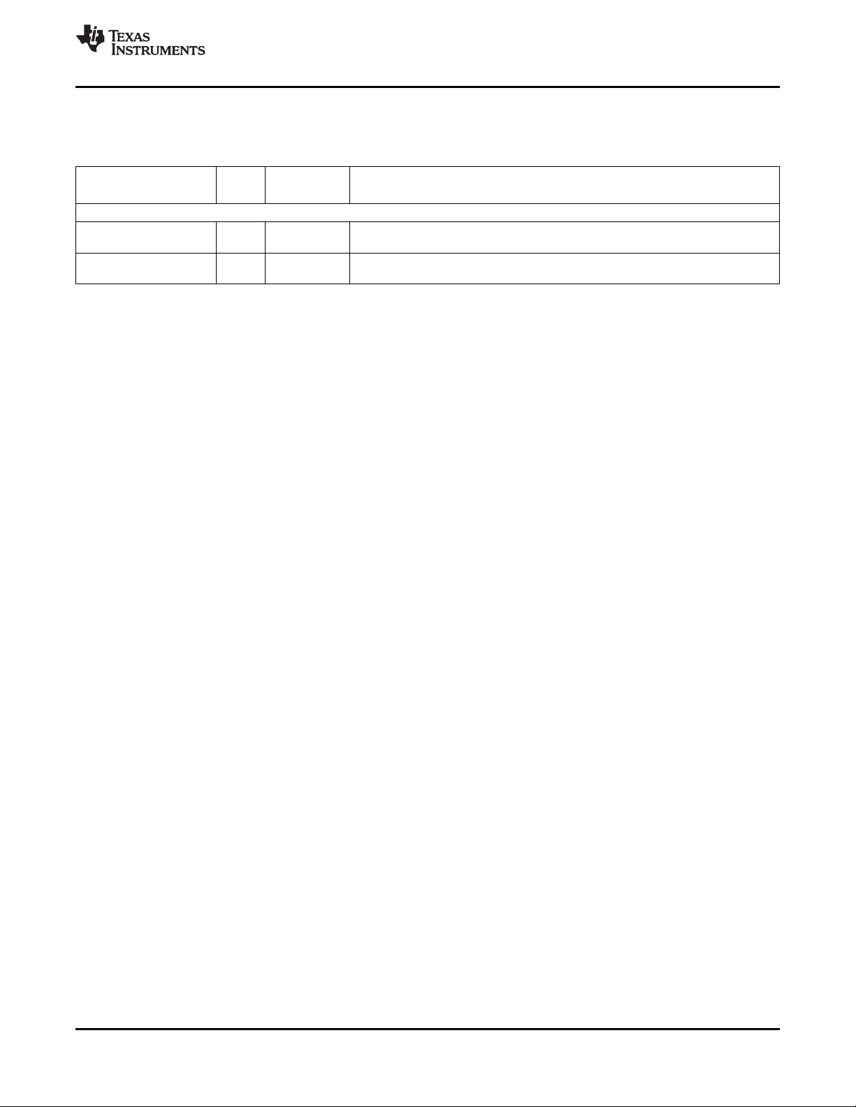
TMS320DM6467
www.ti.com
SPRS403G–DECEMBER 2007–REVISED OCTOBER 2010
3.7.15 Inter-Integrated Circuit (I2C)
Table 3-19. I2C Terminal Functions
SIGNAL
NAME NO.
SCL U5 I/O/Z
SDA U4 I/O/Z
(1) I = Input, O = Output, Z = High impedance, S = Supply voltage, GND = Ground, A = Analog signal
(2) Specifies the operating I/O supply voltage for each signal
TYPE
(1)
(2)
OTHER
I2C
- I2C clock output SCL. For proper device operation, this pin must be pulled up via
DV
DD33
- I2C bidirectional data signal SDA. For proper device operation, this pin must be
DV
DD33
external resistor.
pulled up via external resistor.
DESCRIPTION
Copyright © 2007–2010, Texas Instruments Incorporated Device Overview 59
Submit Documentation Feedback
Product Folder Link(s): TMS320DM6467
Page 60

TMS320DM6467
SPRS403G–DECEMBER 2007–REVISED OCTOBER 2010
www.ti.com
3.7.16 Serial Peripheral Interface (SPI)
Table 3-20. SPI Terminal Functions
SIGNAL
NAME NO.
SPI_CLK V1 I/O/Z SPI clock
SPI_EN T5 I/O/Z SPI device enable
SPI_CS0 T4 I/O/Z SPI chip select 0
SPI_CS1 U3 I/O/Z SPI chip select 1
SPI_SOMI R5 I/O/Z SPI slave out, master in data pin
SPI_SIMO P5 I/O/Z SPI slave in, master out data pin
(1) I = Input, O = Output, Z = High impedance, S = Supply voltage, GND = Ground, A = Analog signal
(2) IPD = Internal pulldown, IPU = Internal pullup. For more detailed information on pullup/pulldown resistors and situations where external
pullup/pulldown resistors are required, see Section 4.8.1, Pullup/Pulldown Resistors.
(3) Specifies the operating I/O supply voltage for each signal
TYPE
(1)
OTHER
IPD
DV
IPD
DV
IPD
DV
IPD
DV
IPD
DV
IPD
DV
DD33
DD33
DD33
DD33
DD33
DD33
(2) (3)
DESCRIPTION
SPI
60 Device Overview Copyright © 2007–2010, Texas Instruments Incorporated
Submit Documentation Feedback
Product Folder Link(s): TMS320DM6467
Page 61

TMS320DM6467
www.ti.com
SPRS403G–DECEMBER 2007–REVISED OCTOBER 2010
3.7.17 Multichannel Audio Serial Port (McASP)
Table 3-21. Multichannel Audio Serial Port (McASP) Terminal Functions
SIGNAL
NAME NO.
ACLKR0 AA2 I/O/Z McASP0 receive bit clock
AHCLKR0 AB2 I/O/Z McASP0 receive high-frequency master clock
AFSR0 Y3 I/O/Z McASP0 receive frame sync
ACLKX0 AA1 I/O/Z McASP0 transmit bit clock
AHCLKX0 Y1 I/O/Z McASP0 transmit high-frequency master clock
AFSX0 Y4 I/O/Z McASP0 transmit frame sync
AXR0[3] W3
AXR0[2] W4
AXR0[1] V4
AXR0[0] V3
AMUTE0 Y2 I/O/Z McASP0 mute output
AMUTEIN0 AA3 I McASP0 mute input
ACLKX1 W1 I/O/Z McASP1 transmit bit clock
AHCLKX1 W2 I/O/Z McASP1 transmit high-frequency master clock
AXR1[0] V2 I/O/Z McASP1 transmit data pin [0]
(1) I = Input, O = Output, Z = High impedance, S = Supply voltage, GND = Ground, A = Analog signal
(2) IPD = Internal pulldown, IPU = Internal pullup. For more detailed information on pullup/pulldown resistors and situations where external
pullup/pulldown resistors are required, see Section 4.8.1, Pullup/Pulldown Resistors.
(3) Specifies the operating I/O supply voltage for each signal
TYPE
(1)
OTHER
(2) (3)
McASP0
IPD
DV
DD33
IPD
DV
DD33
IPD
DV
DD33
IPD
DV
DD33
IPD
DV
DD33
IPD
DV
DD33
I/O/Z McASP0 transmit/receive data pins [3:0]
DV
IPD
DD33
IPD
DV
DD33
IPD
DV
DD33
McASP1
IPD
DV
DD33
IPD
DV
DD33
IPD
DV
DD33
DESCRIPTION
Copyright © 2007–2010, Texas Instruments Incorporated Device Overview 61
Submit Documentation Feedback
Product Folder Link(s): TMS320DM6467
Page 62
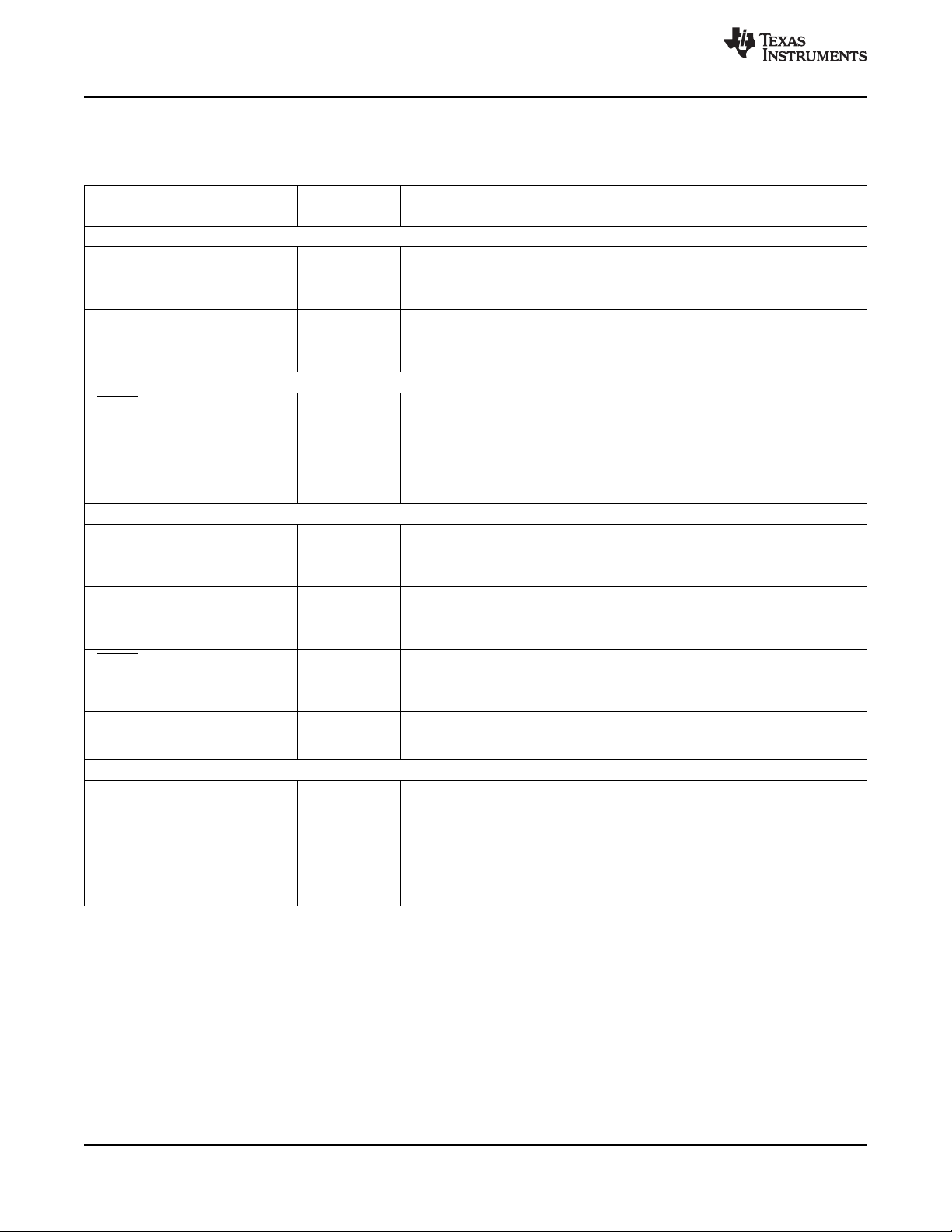
TMS320DM6467
SPRS403G–DECEMBER 2007–REVISED OCTOBER 2010
www.ti.com
3.7.18 Clock Recovery Generator (CRGEN)
Table 3-22. Clock Recovery Generator (CRGEN) Terminal Functions
SIGNAL
NAME NO.
URXD2/
CRG1_VCXI/ IPD
GP[39]/ DV
AB20 I/O/Z When CRGEN1 is enabled (PINMUX0.CRGMUX = 001), this pin is CRGEN1 input
CRG0_VCXI
UTXD2/ URCTX2/
CRG1_PO/ IPD
GP[40]/ DV
AA19 I/O/Z When CRGEN1 is enabled (PINMUX0.CRGMUX = 001), this pin is CRGEN1
CRG0_PO
UCTS2/ USD2/
CRG0_VCXI/ IPU
GP[42]/ DV
AC21 I/O/Z When CRGEN0 on UART2/PWM muxing is enabled (PINMUX0.CRGMUX = 10x),
TS1_PSTO
PWM0/ This pin is multiplexed between PWM0, CRGEN0, and TSIF1.
CRG0_PO/ W17 O/Z When CRGEN0 on UART2/PWM muxing is enabled (PINMUX0.CRGMUX = 10x),
TS1_ENAO this pin is CRGEN0 pulse width modulation output, CRG0_PO (O/Z).
URXD2/
CRG1_VCXI/ IPD
GP[39]/ DV
AB20 I/O/Z When CRGEN1 is enabled (PINMUX0.CRGMUX = x01), this pin is CRGEN1 input
CRG0_VCXI
UTXD2/ URCTX2/
CRG1_PO/ IPD
GP[40]/ DV
AA19 I/O/Z When CRGEN1 is enabled (PINMUX0.CRGMUX = x01), this pin is CRGEN1
CRG0_PO
UCTS2/ USD2/
CRG0_VCXI/ IPU
GP[42]/ DV
AC21 I/O/Z When CRGEN0 on UART2/PWM muxing is enabled (PINMUX0.CRGMUX = 10x),
TS1_PSTO
PWM0/ This pin is multiplexed between PWM0, CRGEN0, and TSIF1.
CRG0_PO/ W17 O/Z When CRGEN0 on UART2/PWM muxing is enabled (PINMUX0.CRGMUX = 10x),
TS1_ENAO this pin is CRGEN0 pulse width modulation output, CRG0_PO (O/Z).
URXD2/
CRG1_VCXI/ IPD
GP[39]/ DV
AB20 I/O/Z When CRGEN0 on UART2 muxing is enabled (PINMUX0.CRGMUX = 110), this
CRG0_VCXI
UTXD2/ URCTX2/
CRG1_PO/ IPD
GP[40]/ DV
AA19 I/O/Z When CRGEN0 on UART2 muxing is enabled (PINMUX0.CRGMUX = 110), this
CRG0_PO
(1) I = Input, O = Output, Z = High impedance, S = Supply voltage, GND = Ground, A = Analog signal
(2) IPD = Internal pulldown, IPU = Internal pullup. For more detailed information on pullup/pulldown resistors and situations where external
pullup/pulldown resistors are required, see Section 4.8.1, Pullup/Pulldown Resistors.
(3) Specifies the operating I/O supply voltage for each signal
TYPE
(1)
OTHER
(2) (3)
DESCRIPTION
CRGEN1 ONLY MODE (PINMUX0.CRGMUX = 001)
This pin is multiplexed between UART2, CRGEN1, GPIO, and CRGEN0.
DD33
clock from external VCXO, CRG1_VCXI (I).
This pin is multiplexed between UART2, CRGEN1, GPIO, and CRGEN0.
DD33
pulse width modulation output, CRG1_PO (O/Z).
CRGEN0 ONLY (UART2/PWM0 MUX) MODE (PINMUX0.CRGMUX = 100)
This pin is multiplexed between UART2, CRGEN0, GPIO, and TSIF1.
DD33
this pin is CRGEN0 input clock from external VCXO, CRG0_VCXI (I).
–
DV
DD33
CRGEN0 AND CRGEN1 MODE (PINMUX0.CRGMUX = 101)
This pin is multiplexed between UART2, CRGEN1, GPIO, and CRGEN0.
DD33
clock from external VCXO, CRG1_VCXI (I).
This pin is multiplexed between UART2, CRGEN1, GPIO, and CRGEN0.
DD33
pulse width modulation output, CRG1_PO (O/Z).
This pin is multiplexed between UART2, CRGEN0, GPIO, and TSIF1.
DD33
this pin is CRGEN0 input clock from external VCXO, CRG0_VCXI (I).
–
DV
DD33
CRGEN0 ONLY (UART2 MUX) MODE (PINMUX0.CRGMUX = 110)
This pin is multiplexed between UART2, CRGEN1, GPIO, and CRGEN0.
DD33
pin is CRGEN0 input clock from external VCXO, CRG0_VCXI (I).
This pin is multiplexed between UART2, CRGEN1, GPIO, and CRGEN0.
DD33
pin is CRGEN0 pulse width modulation output, CRG0_PO (O/Z).
62 Device Overview Copyright © 2007–2010, Texas Instruments Incorporated
Submit Documentation Feedback
Product Folder Link(s): TMS320DM6467
Page 63

TMS320DM6467
www.ti.com
SPRS403G–DECEMBER 2007–REVISED OCTOBER 2010
3.7.19 UART0
Table 3-23. UART0 Terminal Functions
SIGNAL
NAME NO.
Actual UART0 pin functions are determined by the PINMUX0 and PINMUX1 register bit settings. For more details, see
Section 4.7.3, Pin Multiplexing.
URXD0/ IPD When UART0 UART functional muxing is selected (PINMUX1.UART0CTL = 0x)
TS1_DIN DV
AB13 I
UTXD0/
URCTX0/ Y13 I/O/Z
TS1_PSTIN
URTS0 /
UIRTX0/ AA13 I/O/Z
TS1_EN_WAITO
UCTS0 / USD0 AC12 I/O/Z
UDTR0 /
TS0_ENAO/ Y12 I/O/Z
GP[36]
UDSR0 /
TS0_PSTO/ AB11 I/O/Z
GP[37]
UDCD0 /
TS0_WAITIN/ AA11 I/O/Z
GP[38]
URIN0 /GP[8]/ IPD
TS1_WAITIN DV
URXD0/ IPD When UART0 UART functional muxing is selected (PINMUX1.UART0CTL = 0x)
TS1_DIN DV
Y11 I/O/Z (PINMUX1.UART0CTL = 00) and TSIF1 output on UART/PWM muxing is not
AB13 I
UTXD0/
URCTX0/ Y13 I/O/Z
TS1_PSTIN
URTS0 /
UIRTX0/ AA13 I/O/Z
TS1_EN_WAITO
UCTS0 / IPU
USD0 DV
AC12 I/O/Z and TSIF1 input on UART0 muxing is not enabled (PINMUX0.TSSIMUX ≠ 01), this
(1) IPD = Internal pulldown, IPU = Internal pullup. For more detailed information on pullup/pulldown resistors and situations where external
pullup/pulldown resistors are required, see Section 4.8.1, Pullup/Pulldown Resistors.
(2) I = Input, O = Output, Z = High impedance, S = Supply voltage, GND = Ground, A = Analog signal
(3) Specifies the operating I/O supply voltage for each signal
TYPE
(1)
OTHER
(2) (3)
UART0 WITH MODEM CONTROL (PINMUX1.UART0CTL = 00)
This pin is multiplexed between UART0 and TSIF1.
DD33
and TSIF1 input on UART0 muxing is not enabled (PINMUX0.TSSIMUX ≠ 01), this
pin is UART0 receive data, URXD0 (I).
This pin is multiplexed between UART0 and TSIF1.
IPD When UART0 UART functional muxing is selected (PINMUX1.UART0CTL = 0x)
DV
DD33
and TSIF1 input on UART0 muxing is not enabled (PINMUX0.TSSIMUX ≠ 01), this
pin is UART0 transmit data, UTXD0 (O/Z).
This pin is multiplexed between UART0 and TSIF1.
IPU When UART0 UART functional muxing is selected (PINMUX1.UART0CTL = 0x)
DV
DD33
and TSIF1 input on UART0 muxing is not enabled (PINMUX0.TSSIMUX ≠ 01), this
pin is the UART0 request-to-send signal, URTS0 (O/Z).
This pin is multiplexed between UART0 and TSIF1.
IPU When UART0 UART functional muxing is selected (PINMUX1.UART0CTL = 0x)
DV
DD33
and TSIF1 input on UART0 muxing is not enabled (PINMUX0.TSSIMUX ≠ 01), this
pin is the UART0 clear-to-send signal, UCTS0 (I).
This pin is multiplexed between UART0, TSIF0, and GPIO.
IPU When UART0 UART with modem functional muxing is selected
DV
DD33
(PINMUX1.UART0CTL = 00) and TSIF0 output muxing is not enabled
(PINMUX0.PTSOMUX ≠ 1x), this pin is UART0 data-terminal-ready, UDTR0 (O/Z).
This pin is multiplexed between UART0, TSIF0, and GPIO.
IPU When UART0 UART with modem functional muxing is selected
DV
DD33
(PINMUX1.UART0CTL = 00) and TSIF0 output muxing is not enabled
(PINMUX0.PTSOMUX ≠ 1x), this pin is UART0 data-set-ready, UDSR0 (I).
This pin is multiplexed between UART0, TSIF0, and GPIO.
IPU When UART0 UART with modem functional muxing is selected
DV
DD33
(PINMUX1.UART0CTL = 00) and TSIF0 output muxing is not enabled
(PINMUX0.PTSOMUX ≠ 1x), this pin is UART0 data-carrier-detect, UDCD0 (I).
This pin is multiplexed between UART0, GPIO, and TSIF1.
When UART0 UART with modem functional muxing is selected
DD33
enabled (PINMUX0.TSSOMUX ≠ 11), this pin is the UART0 ring indicator,
URIN0 (I).
UART0 WITHOUT MODEM CONTROL (PINMUX1.UART0CTL = 01)
This pin is multiplexed between UART0 and TSIF1.
DD33
and TSIF1 input on UART0 muxing is not enabled (PINMUX0.TSSIMUX ≠ 01), this
pin is UART0 receive data, URXD0 (I).
This pin is multiplexed between UART0 and TSIF1.
IPD When UART0 UART functional muxing is selected (PINMUX1.UART0CTL = 0x)
DV
DD33
and TSIF1 input on UART0 muxing is not enabled (PINMUX0.TSSIMUX ≠ 01), this
pin is UART0 transmit data, UTXD0 (O/Z).
This pin is multiplexed between UART0 and TSIF1.
IPU When UART0 UART functional muxing is selected (PINMUX1.UART0CTL = 0x)
DV
DD33
and TSIF1 input on UART0 muxing is not enabled (PINMUX0.TSSIMUX ≠ 01), this
pin is UART0 request-to-send signal, URTS0 (O/Z).
When UART0 UART functional muxing is selected (PINMUX1.UART0CTL = 0x)
DD33
pin is UART0 clear-to-send signal, UCTS0 (I).
DESCRIPTION
Copyright © 2007–2010, Texas Instruments Incorporated Device Overview 63
Submit Documentation Feedback
Product Folder Link(s): TMS320DM6467
Page 64

TMS320DM6467
SPRS403G–DECEMBER 2007–REVISED OCTOBER 2010
Table 3-23. UART0 Terminal Functions (continued)
SIGNAL
NAME NO.
URXD0/ IPD
TS1_DIN DV
AB13 I When TSIF1 input on UART0 muxing is not enabled (PINMUX0.TSSIMUX ≠ 01),
UTXD0/
URCTX0/ Y13 I/O/Z
TS1_PSTIN
URTS0/
UIRTX0/ AA13 I/O/Z
TS1_EN_WAITO
UCTS0/ IPU
USD0 DV
AC12 I/O/Z and TSIF1 input on UART0 muxing is not enabled (PINMUX0.TSSIMUX ≠ 01), this
TYPE
(1)
OTHER
(2) (3)
UART0 IrDA/CIR FUNCTION (PINMUX1.UART0CTL = 1x)
DD33
IPD When UART0 IrDA/CIR functional muxing is selected (PINMUX1.UART0CTL = 1x)
DV
DD33
IPU When UART0 IrDA/CIR functional muxing is selected (PINMUX1.UART0CTL = 1x)
DV
DD33
DD33
www.ti.com
DESCRIPTION
This pin is multiplexed between UART0 and TSIF1.
this pin is UART0 IrDA/CIR receive data, URXD0 (I).
This pin is multiplexed between UART0 and TSIF1.
and TSIF1 input on UART0 muxing is not enabled (PINMUX0.TSSIMUX ≠ 01), this
pin is UART0 CIR transmit data, URCTX0 (O/Z).
This pin is multiplexed between UART0 and TSIF1.
and TSIF1 input on UART0 muxing is not enabled (PINMUX0.TSSIMUX ≠ 01), this
pin is UART0 IrDA transmit data, UIRTX0 (O/Z).
When UART0 IrDA/CIR functional muxing is selected (PINMUX1.UART0CTL = 1x)
pin is UART0 IrDA transceiver control, USD0 (O/Z).
64 Device Overview Copyright © 2007–2010, Texas Instruments Incorporated
Submit Documentation Feedback
Product Folder Link(s): TMS320DM6467
Page 65

TMS320DM6467
www.ti.com
SPRS403G–DECEMBER 2007–REVISED OCTOBER 2010
3.7.20 UART1
Table 3-24. UART1 Terminal Functions
SIGNAL
NAME NO.
Actual UART1 pin functions are determined by the PINMUX0 and PINMUX1 register bit settings. For more details, see
Section 4.7.3, Pin Multiplexing.
URXD1/
TS0_DIN7/ Y18 I/O/Z
GP[23]
UTXD1/ This pin is multiplexed between UART1, TSIF0, and GPIO.
URCTX1/ IPD When UART1 UART functional muxing is selected (PINMUX1.UART1CTL = 0x)
TS0_DOUT7/ DV
AB19 I/O/Z
GP[24] UART1 transmit data, UTXD1 (O/Z).
URTS1 /UIRTX1/
TS0_WAITO/ AA18 I/O/Z
GP[25]
UCTS1 /USD1
TS0_EN_WAITO/ Y17 I/O/Z
GP[26]
URXD1/
TS0_DIN7/ Y18 I/O/Z
GP[23]
UTXD1/ This pin is multiplexed between UART1, TSIF0, and GPIO.
URCTX1/ IPD When UART1 UART functional muxing is selected (PINMUX1.UART1CTL = 0x)
TS0_DOUT7/ DV
AB19 I/O/Z
GP[24] UART1 transmit data, UTXD1 (O/Z).
URXD1/
TS0_DIN7/ Y18 I/O/Z
GP[23]
UTXD1/URCTX1/
TS0_DOUT7/ AB19 I/O/Z
GP[24]
URTS1/UIRTX1/
TS0_WAITO/ AA18 I/O/Z
GP[25]
UCTS1/USD1/
TS0_EN_WAITO/ Y17 I/O/Z
GP[26]
(1) IPD = Internal pulldown, IPU = Internal pullup. For more detailed information on pullup/pulldown resistors and situations where external
pullup/pulldown resistors are required, see Section 4.8.1, Pullup/Pulldown Resistors.
(2) I = Input, O = Output, Z = High impedance, S = Supply voltage, GND = Ground, A = Analog signal
(3) Specifies the operating I/O supply voltage for each signal
TYPE
(1)
OTHER
(2) (3)
UART1 WITH FLOW CONTROL (PINMUX1.UART1CTL = 00)
This pin is multiplexed between UART1, TSIF0, and GPIO.
IPD When UART1 UART functional muxing is selected (PINMUX1.UART1CTL = 0x)
DV
DD33
DD33
and TSIF0 serial input is not enabled (PINMUX0.PTSIMUX ≠ 11), this pin is
UART1 receive data, URXD1 (I).
and TSIF0 serial output is not enabled (PINMUX0.PTSIMUX ≠ 11), this pin is
This pin is multiplexed between UART1, TSIF0, and GPIO.
IPU When UART1 UART with flow control muxing is selected (PINMUX1.UART1CTL =
DV
DD33
00) and TSIF0 input is not enabled (PINMUX0.PTSIMUX ≠ 0x), this pin is UART1
request-to-send, URTS1 (O/Z).
This pin is multiplexed between UART1, TSIF0, and GPIO.
IPU When UART1 UART with flow control muxing is selected (PINMUX1.UART1CTL =
DV
DD33
00) and TSIF0 input is not enabled (PINMUX0.PTSIMUX ≠ 0x), this pin is UART1
clear-to-send, UCTS1 (I).
UART1 WITHOUT FLOW CONTROL (PINMUX1.UART1CTL = 01)
This pin is multiplexed between UART1, TSIF0, and GPIO.
IPD When UART1 UART functional muxing is selected (PINMUX1.UART1CTL = 0x)
DV
DD33
DD33
and TSIF0 serial input is not enabled (PINMUX0.PTSIMUX ≠ 11), this pin is
UART1 receive data, URXD1 (I).
and TSIF0 serial output is not enabled (PINMUX0.PTSIMUX ≠ 11), this pin is
UART1 IrDA/CIR FUNCTION (PINMUX1.UART1CTL = 10)
This pin is multiplexed between UART1, TSIF0, and GPIO.
IPD When UART1 IrDA/CIR functional muxing is selected (PINMUX1.UART1CTL = 10)
DV
DD33
and TSIF0 serial input is not enabled (PINMUX0.PTSIMUX ≠ 11), this pin is
UART1 receive data, URXD1 (I).
This pin is multiplexed between UART1, TSIF0, and GPIO.
IPD When UART1 IrDA/CIR functional muxing is selected (PINMUX1.UART1CTL = 10)
DV
DD33
and TSIF0 serial output is not enabled (PINMUX0.PTSOMUX ≠ 11), this pin is
UART1 CIR transmit data, URCTX1 (O/Z).
This pin is multiplexed between UART1, TSIF0, and GPIO.
IPU When UART1 IrDA/CIR functional muxing is selected (PINMUX1.UART1CTL = 10)
DV
DD33
and TSIF0 input is not enabled (PINMUX0.PTSIMUX = 0x), this pin is UART1 IrDA
transmit data, UIRTX1 (O/Z).
This pin is multiplexed between UART1, TSIF0, and GPIO.
IPU When UART1 IrDA/CIR functional muxing is selected (PINMUX1.UART1CTL = 10)
DV
DD33
and TSIF0 input is not enabled (PINMUX0.PTSIMUX = 0x), this pin is UART1 IrDA
tranceiver control, USD1 (O/Z).
DESCRIPTION
Copyright © 2007–2010, Texas Instruments Incorporated Device Overview 65
Submit Documentation Feedback
Product Folder Link(s): TMS320DM6467
Page 66

TMS320DM6467
SPRS403G–DECEMBER 2007–REVISED OCTOBER 2010
www.ti.com
3.7.21 UART2
Table 3-25. UART2 Terminal Functions
SIGNAL
NAME NO.
Actual UART2 pin functions are determined by the PINMUX0 and PINMUX1 register bit settings. For more details, see
Section 4.7.3, Pin Multiplexing.
URXD2/ This pin is multiplexed between UART2, CRGEN1, GPIO, and CRGEN0.
CRG1_VCXI/ IPD When UART2 UART functional muxing is selected (PINMUX1.UART2CTL = 0x)
GP[39]/ DV
AB20 I/O/Z
CRG0_VCXI UART2 receive data, URXD2 (I).
UTXD2/
URCTX2/
CRG1_PO/ AA19 I/O/Z
GP[40]/
CRG0_PO
URTS2 /UIRTX2/
TS0_PSTIN/ AC20 I/O/Z
GP[41]
UCTS2 /USD2/ This pin is multiplexed between UART2, CRGEN0, GPIO, and TSIF1.
CRG0_VCXI/ IPU When UART2 UART with flow control muxing is selected (PINMUX1.UART2CTL =
GP[42]/ DV
AC21 I/O/Z
TS1_PSTO UART2 clear-to-send, UCTS2 (I).
URXD2/ This pin is multiplexed between UART2, CRGEN1, GPIO, and CRGEN0.
CRG1_VCXI/ IPD When UART2 UART functional muxing is selected (PINMUX1.UART2CTL = 0x)
GP[39]/ DV
AB20 I/O/Z
CRG0_VCXI UART2 receive data, URXD2 (I).
UTXD2/
URCTX2/
CRG1_PO/ AA19 I/O/Z
GP[40]/
CRG0_PO
URXD2/ This pin is multiplexed between UART2, CRGEN1, GPIO, and CRGEN0.
CRG1_VCXI/ IPD When UART2 IrDA/CIR functional muxing is selected (PINMUX1.UART2CTL = 10)
GP[39]/ DV
AB20 I/O/Z
CRG0_VCXI UART2 receive data, URXD2 (I).
UTXD2/URCTX2/ This pin is multiplexed between UART2, CRGEN1, GPIO, and CRGEN0.
CRG1_PO/ IPD When UART2 IrDA/CIR functional muxing is selected (PINMUX1.UART2CTL = 10)
GP[40]/ DV
AA19 I/O/Z
CRG0_PO UART2 CIR transmit data, URCTX2 (O/Z).
URTS2/UIRTX2/
TS0_PSTIN/ AC20 I/O/Z
GP[41]
UCTS2/USD2/ This pin is multiplexed between UART2, CRGEN0, GPIO, and TSIF1.
CRG0_VCXI/ IPU When UART2 IrDA/CIR functional muxing is selected (PINMUX1.UART2CTL = 10)
GP[42]/ DV
AC21 I/O/Z
TS1_PSTO pin is UART2 IrDA tranceiver control, USD2 (O/Z).
(1) IPD = Internal pulldown, IPU = Internal pullup. For more detailed information on pullup/pulldown resistors and situations where external
pullup/pulldown resistors are required, see Section 4.8.1, Pullup/Pulldown Resistors.
(2) I = Input, O = Output, Z = High impedance, S = Supply voltage, GND = Ground, A = Analog signal
(3) Specifies the operating I/O supply voltage for each signal
TYPE
(1)
OTHER
(2) (3)
UART2 WITH FLOW CONTROL (PINMUX1.UART2CTL = 00)
DD33
and CRGEN0/1 are not enabled (PINMUX0.CRGMUX ≠ x01, 110), this pin is
This pin is multiplexed between UART2, CRGEN1, GPIO, and CRGEN0.
IPD When UART2 UART functional muxing is selected (PINMUX1.UART2CTL = 0x)
DV
DD33
and CRGEN0/1 are not enabled (PINMUX0.CRGMUX ≠ x01, 110), this pin is
UART2 transmit data, UTXD2 (O/Z).
This pin is multiplexed between UART2, TSIF0, and GPIO.
IPU When UART2 UART with flow control muxing is selected (PINMUX1.UART2CTL =
DV
DD33
DD33
00) and TSIF0 input is not enabled (PINMUX0.PTSIMUX = 0x), this pin is UART2
request-to-send, URTS2 (O/Z).
00) and TSIF1 output is not enabled (PINMUX0.PTSOMUX = 0x), this pin is
UART2 WITHOUT FLOW CONTROL (PINMUX1.UART2CTL = 01)
DD33
and CRGEN0/1 are not enabled (PINMUX0.CRGMUX ≠ x01, 110), this pin is
This pin is multiplexed between UART2, CRGEN1, GPIO, and CRGEN0.
IPD When UART2 UART functional muxing is selected (PINMUX1.UART2CTL = 0x)
DV
DD33
and CRGEN0/1 are not enabled (PINMUX0.CRGMUX ≠ x01, 110), this pin is
UART2 transmit data, UTXD2 (O/Z).
UART2 IrDA/CIR FUNCTION (PINMUX1.UART2CTL = 10)
DD33
DD33
and CRGEN0/1 are not enabled (PINMUX0.CRGMUX ≠ x01, 110), this pin is
and CRGEN0/1 are not enabled (PINMUX0.CRGMUX ≠ x01, 110), this pin is the
This pin is multiplexed between UART2, TSIF0, and GPIO.
IPU When UART2 IrDA/CIR functional muxing is selected (PINMUX1.UART2CTL = 10)
DV
DD33
DD33
and TSIF0 input is not enabled (PINMUX0.PTSIMUX = 0x), this pin is UART2 IrDA
transmit data, UIRTX2 (O/Z).
and CRGEN0 on TSIF0 output is not enabled (PINMUX0.TSSOMUX = 0x), this
DESCRIPTION
66 Device Overview Copyright © 2007–2010, Texas Instruments Incorporated
Submit Documentation Feedback
Product Folder Link(s): TMS320DM6467
Page 67

TMS320DM6467
www.ti.com
SPRS403G–DECEMBER 2007–REVISED OCTOBER 2010
3.7.22 Pulse-Width Modulation (PWM)
Table 3-26. PWM Terminal Functions
SIGNAL
NAME NO.
PWM0/
CRG0_PO/ W17 O/Z
TS1_ENAO
PWM1/ –
TS1_DOUT DV
(1) I = Input, O = Output, Z = High impedance, S = Supply voltage, GND = Ground, A = Analog signal
(2) Specifies the operating I/O supply voltage for each signal
W18 O/Z When not overridden by TSIF1 output muxing (PINMUX0.TSSOMUX ≠ 11), this pin
TYPE
(1)
(2)
OTHER
PWM0
– When not overridden by CRGEN or TSIF1 output muxing (PINMUX0.CRGMUX ≠
DV
DD33
DD33
This pin is multiplexed between PWM0, CRGEN0, and TSIF1.
10x and PINMUX0.TSSOMUX ≠ 11), this pin is the pulse width modulation 0 output,
PWM0 (O/Z).
PWM1
This pin is multiplexed between PWM1 and TSIF1.
is the pulse width modulation 1 output, PWM1 (O/Z).
DESCRIPTION
Copyright © 2007–2010, Texas Instruments Incorporated Device Overview 67
Submit Documentation Feedback
Product Folder Link(s): TMS320DM6467
Page 68

TMS320DM6467
SPRS403G–DECEMBER 2007–REVISED OCTOBER 2010
www.ti.com
3.7.23 Timers (Timer 0, Timer 1, and Timer 2)
Table 3-27. Timer 0, Timer 1, and Timer 2 Terminal Functions
SIGNAL
NAME NO.
TINP0L Y7 I/O/Z
TINP0U AA6 I/O/Z
TOUT0L W8 I/O/Z
TOUT0U W7 I/O/Z
TINP1L Y6 I/O/Z
TOUT1L AA5 I/O/Z
TOUT1U AB4 I/O/Z
TOUT2 Y5 I/O/Z Watchdog timer output.
(1) I = Input, O = Output, Z = High impedance, S = Supply voltage, GND = Ground, A = Analog signal
(2) IPD = Internal pulldown, IPU = Internal pullup. For more detailed information on pullup/pulldown resistors and situations where external
pullup/pulldown resistors are required, see Section 4.8.1, Pullup/Pulldown Resistors.
(3) Specifies the operating I/O supply voltage for each signal
TYPE
(1)
(2) (3)
OTHER
DESCRIPTION
Timer 0
IPD Timer0 lower input. This pin is the Timer0 input for 64-mode operation. For 32-bit
DV
DD33
timer operation, this pin is the input for the Timer0 lower 32-bit counter.
IPD Timer0 upper input. For 32-bit timer operation, this pin is the input for the Timer0
DV
DD33
upper 32-bit counter. Not used for Timer0 64-mode operation.
IPD Timer0 lower output. This pin is the Timer0 output for 64-mode operation. For 32-bit
DV
DD33
timer operation, this pin is the output for the Timer0 lower 32-bit counter.
IPD Timer0 upper output. For 32-bit timer operation, this pin is the output for the Timer0
DV
DD33
upper 32-bit counter. Not used for Timer0 64-mode operation.
Timer 1
IPD Timer1 lower input. This pin is the Timer1 input for 64-mode operation. For 32-bit
DV
DD33
timer operation, this pin is the input for the Timer1 lower 32-bit counter.
IPD Timer1 lower output. This pin is the Timer1 output for 64-mode operation. For 32-bit
DV
DD33
timer operation, this pin is the output for the Timer1 lower 32-bit counter.
IPD Timer1 upper output. For 32-bit timer operation, this pin is the output for the Timer1
DV
DD33
upper 32-bit counter. Not used for Timer1 64-mode operation.
WATCHDOG TIMER (Timer 2)
IPD
DV
DD33
68 Device Overview Copyright © 2007–2010, Texas Instruments Incorporated
Submit Documentation Feedback
Product Folder Link(s): TMS320DM6467
Page 69

TMS320DM6467
www.ti.com
SPRS403G–DECEMBER 2007–REVISED OCTOBER 2010
3.7.24 ATA
Table 3-28. ATA Terminal Functions
SIGNAL
NAME NO.
ATA is enabled by the PINMUX0.ATAEN =1 (and PCIEN = 0). For more detailed information on the ATA pin muxing, see Section 4.7.3.1,
PCI, HPI, EMIFA, and ATA Pin Muxing.
PCI_CBE0/
ATA_CS0 / F4 I/O/Z
GP[33]/EM_A[18]
PCI_CBE1/
ATA_CS1 / C2 I/O/Z
GP[32]/EM_A[19]
PCI_RSV4/ DIOW / IPU This pin is multiplexed between PCI, ATA, GPIO, and EMIFA.
GP[20]/EM_WAIT4 DV
PCI_RSV3/ DIOR / IPU This pin is multiplexed between PCI, ATA, GPIO, and EMIFA.
GP[19]/EM_WAIT5 DV
PCI_RSV5/IORDY/ IPU This pin is multiplexed between PCI, ATA, GPIO, and EMIFA.
GP[21]/EM_WAIT3 DV
A11 I/O/Z
E10 I/O/Z
D11 I/O/Z
PCI_RST/
DA2/ C10 I/O/Z
GP[13]/EM_A[22]
PCI_RSV0/DA1/ IPD This pin is multiplexed between PCI, ATA, GPIO, and EMIFA.
GP[16]/EM_A[21] DV
PCI_RSV1/DA0/ IPD This pin is multiplexed between PCI, ATA, GPIO, and EMIFA.
GP[17]/EM_A[20] DV
PCI_RSV2/INTRQ/ IPD This pin is multiplexed between PCI, ATA, GPIO, and EMIFA.
GP[18]/EM_RSV0 DV
A9 I/O/Z
E9 I/O/Z
B10 I/O/Z
PCI_REQ/
DMARQ/ B9 I/O/Z
GP[11]/EM_CS5
PCI_GNT/ This pin is multiplexed between PCI, ATA, GPIO, and EMIFA.
DMACK / D10 I/O/Z When ATA is enabled, this pin is the ATA DMA acknowledge output, DMACK
GP[12]/EM_CS4 (O/Z).
PCI_IDSEL/ This pin is multiplexed between PCI, ATA, and EMIFA.
HDDIR/ E8 I/O/Z When ATA is enabled, this pin is the data direction indicator for external buffer
EM_R/W control, HDDIR (O/Z).
TYPE
(1)
(2) (3)
OTHER
DESCRIPTION
ATA
IPU This pin is multiplexed between PCI, ATA, GPIO, and EMIFA.
DV
DD33
When ATA is enabled, this pin is ATA chip select 0 output, ATA_CS0 (O/Z).
IPU This pin is multiplexed between PCI, ATA, GPIO, and EMIFA.
DV
DD33
DD33
DD33
DD33
When ATA is enabled, this pin is ATA chip select 1 output, ATA_CS1 (O/Z).
When ATA is enabled, this pin is the ATA write strobe output, DIOW (O/Z).
When ATA is enabled, this pin is the ATA read strobe output, DIOR (O/Z).
When ATA is enabled, this pin is ATA I/O ready, IORDY (I).
IPD This pin is multiplexed between PCI, ATA, GPIO, and EMIFA.
DV
DD33
DD33
DD33
DD33
When ATA is enabled, this pin is ATA address bit 2, DA2 (O/Z).
When ATA is enabled, this pin is ATA address bit 1, DA1 (O/Z).
When ATA is enabled, this pin is ATA address bit 0, DA0 (O/Z).
When ATA is enabled, this pin is the ATA interrupt request input, INTRQ (I).
IPU This pin is multiplexed between PCI, ATA, GPIO, and EMIFA.
DV
DD33
When ATA is enabled, this pin is the ATA DMA request input, DMARQ (I).
IPU
DV
DD33
IPU
DV
DD33
(1) I = Input, O = Output, Z = High impedance, S = Supply voltage, GND = Ground, A = Analog signal
(2) IPD = Internal pulldown, IPU = Internal pullup. For more detailed information on pullup/pulldown resistors and situations where external
pullup/pulldown resistors are required, see Section 4.8.1, Pullup/Pulldown Resistors.
(3) Specifies the operating I/O supply voltage for each signal
Copyright © 2007–2010, Texas Instruments Incorporated Device Overview 69
Submit Documentation Feedback
Product Folder Link(s): TMS320DM6467
Page 70

TMS320DM6467
SPRS403G–DECEMBER 2007–REVISED OCTOBER 2010
Table 3-28. ATA Terminal Functions (continued)
SIGNAL
NAME NO.
PCI_AD31/
DD15/ A8
HD31/ EM_A[15]
PCI_AD30/
DD14/ C9
HD30/EM_A[14]
PCI_AD29/
DD13/ B8
HD29/EM_A[13]
PCI_AD28/
DD12/ D9
HD28/EM_A[12]
PCI_AD27/
DD11/ A6
HD27/EM_A[11]
PCI_AD26/
DD10/ C8
HD26/EM_A[10]
PCI_AD25/
DD9/ B6
HD25/EM_A[9]
PCI_AD24/
DD8/ D8
HD24/EM_A[8]
PCI_AD23/
DD7/ B5
HD23/EM_A[7]
PCI_AD22/
DD6/ C7
HD22/EM_A[6]
PCI_AD21/
DD5/ C5
HD21/EM_A[5]
PCI_AD20/
DD4/ D7
HD20/EM_A[4]
PCI_AD19/
DD3/ A4
HD19/EM_A[3]
PCI_AD18/
DD2/ E7
HD18/EM_A[2]
PCI_AD17/
DD1/ B4
HD17/EM_A[1]
PCI_AD16/
DD0/ C6
HD16/EM_A[0]
(1)
TYPE
I/O/Z When ATA is enabled, these pins are the ATA 16-bit bidirectional data bus,
OTHER
IPD
DV
(2) (3)
DD33
www.ti.com
DESCRIPTION
These pins are multiplexed between PCI, ATA, HPI, and EMIFA.
DD[15:0] (I/O/Z).
70 Device Overview Copyright © 2007–2010, Texas Instruments Incorporated
Submit Documentation Feedback
Product Folder Link(s): TMS320DM6467
Page 71

TMS320DM6467
www.ti.com
SPRS403G–DECEMBER 2007–REVISED OCTOBER 2010
3.7.25 General Purpose Input/Output (GPIO)
Table 3-29. General Purpose Input/Output (GPIO) Terminal Functions
SIGNAL
NAME NO.
The DM6467 device does not support GP[47:43], GP[35:34], GP[31:27], GP[15:14], and GP[9] signals (not pinned out).
GP[7:0] pins have dedicated ARM926 and DSP interrupts.
When PCI is used, GP[19:16] pins are reserved.
GP[0] W5 I/O/Z GP[0] (I/O/Z). This pin is general-purpose input/output 0.
GP[1] V5 I/O/Z GP[1] (I/O/Z). This pin is general-purpose input/output 1.
GP[2]/ IPD This pin is multiplexed between GPIO and the audio clock selector.
AUDIO_CLK1 DV
GP[3]/ IPD This pin is multiplexed between GPIO and the audio clock selector.
AUDIO_CLK0 DV
GP[4]/ IPD
STC_CLKIN DV
AA4 I/O/Z
AB3 I/O/Z
AC3 I/O/Z When the STC source clock input is disabled (PINMUX0.STCCK = 0), this pin is
GP[5] B11 I/O/Z This pin is GP[5] (I/O/Z).
GP[6]/ IPD Outputs.
CVDDADJ0 DV
GP[7]/ IPD Outputs.
CVDDADJ1 DV
URIN0/GP[8]/ IPD When UART0 UART with modem functional muxing is not selected
TS1_WAITIN DV
E11 I/O/Z
A12 I/O/Z
Y11 I/O/Z
GP[9] n/a – – GP[9] is not pinned out on this device.
PCI_CLK/GP[10] A10 I/O/Z
PCI_REQ/ This pin is multiplexed between PCI, ATA, GPIO, and EMIFA.
DMARQ/ B9 I/O/Z When 32-bit HPI mode is enabled (PINMUX0.PCIEN = 0, PINMUX0.HPIEN = 1,
GP[11]/EM_CS5 PINMUX0.ATAEN = 0), this pin is GP[11] (I/O/Z).
PCI_GNT/ This pin is multiplexed between PCI, ATA, GPIO, and EMIFA.
DMACK/ D10 I/O/Z When 32-bit HPI mode is enabled (PINMUX0.PCIEN = 0, PINMUX0.HPIEN = 1,
GP[12]/EM_CS4 PINMUX0.ATAEN = 0), this pin is GP[12] (I/O/Z).
PCI_RST/ This pin is multiplexed between PCI, ATA, GPIO, and EMIFA.
DA2/ C10 I/O/Z When 32-bit HPI mode is enabled (PINMUX0.PCIEN = 0, PINMUX0.HPIEN = 1,
GP[13]/EM_A[22] PINMUX0.ATAEN = 0), this pin is GP[13] (I/O/Z).
GP[14:15] n/a – – GP[14:15] are not pinned out on this device.
TYPE
(1)
(2) (3)
OTHER
DESCRIPTION
GPIO
IPD
DV
DD33
IPD
DV
DD33
DD33
DD33
When audio clock 1 is disabled (PINMUX0.AUDCK1 = 0), this pin is GP[2] (I/O/Z).
When audio clock 0 is disabled (PINMUX0.AUDCK0 = 0), this pin is GP[3] (I/O/Z).
This pin is multiplexed between GPIO and the TSIF clock selector.
DD33
GP[4] (I/O/Z).
IPD
DV
DD33
This pin is multiplexed between GPIO and SmartReflex (Voltage Adjust) Control
DD33
When the core voltage adjust function is disabled (VP_DOUT7/VADJEN = 0 at
reset), this pin is GP[6] (I/O/Z).
This pin is multiplexed between GPIO and SmartReflex (Voltage Adjust) Control
DD33
When the core voltage adjust function is disabled (VP_DOUT7/VADJEN = 0 at
reset), this pin is GP[7] (I/O/Z).
This pin is multiplexed between UART0, GPIO, and TSIF1.
DD33
(PINMUX1.UART0CTL = 00) and TSIF1 output on UART/PWM muxing is not
enabled (PINMUX0.TSSOMUX ≠ 11), this pin is GP[8] (I/O/Z).
IPU This pin is multiplexed between PCI and GPIO.
DV
DD33
When PCI is disabled (PINMUX0.PCIEN = 0), this pin is GP[10] (I/O/Z).
IPU
DV
DD33
IPU
DV
DD33
IPD
DV
DD33
(1) I = Input, O = Output, Z = High impedance, S = Supply voltage, GND = Ground, A = Analog signal
(2) IPD = Internal pulldown, IPU = Internal pullup. For more detailed information on pullup/pulldown resistors and situations where external
pullup/pulldown resistors are required, see Section 4.8.1, Pullup/Pulldown Resistors.
(3) Specifies the operating I/O supply voltage for each signal
Copyright © 2007–2010, Texas Instruments Incorporated Device Overview 71
Submit Documentation Feedback
Product Folder Link(s): TMS320DM6467
Page 72

TMS320DM6467
SPRS403G–DECEMBER 2007–REVISED OCTOBER 2010
Table 3-29. General Purpose Input/Output (GPIO) Terminal Functions (continued)
SIGNAL
NAME NO.
PCI_RSV0/DA1/
GP[16]/ A9 I/O/Z
EM_A[21]
PCI_RSV1/DA0/ IPD
GP[17]/EM_A[20] DV
E9 I/O/Z
PCI_RSV2/
INTRQ/ IPD
GP[18]/ DV
B10 I/O/Z
EM_RSV0
PCI_RSV3/DIOR/
GP[19]/ E10 I/O/Z
EM_WAIT5
PCI_RSV4/
DIOW/ IPU
GP[20]/ DV
A11 I/O/Z
EM_WAIT4
PCI_RSV5/
IORDY/ IPU
GP[21]/ DV
D11 I/O/Z
EM_WAIT3
USB_DRVVBUS/ IPD This pin is multiplexed between USB and GPIO.
GP[22] DV
B18 I/O/Z
URXD1/ This pin is multiplexed between UART1, TSIF0, and GPIO.
TS0_DIN7/ Y18 I/O/Z When UART1 GPIO muxing is selected (PINMUX1.UART1CTL = 11) and TSIF0
GP[23] serial input is not enabled (PINMUX0.PTSIMUX ≠ 11), this pin is GP[23] (I/O/Z).
UTXD1/
URCTX1/ IPD
TS0_DOUT7/ DV
AB19 I/O/Z When UART1 GPIO muxing is selected (PINMUX1. UART1CTL = 11) and TSIF0
GP[24]
URTS1/
UIRTX1/ IPD
TS0_WAITO/ DV
AA18 I/O/Z
GP[25]
UCTS1/USD1/
TS0_EN_WAITO/ Y17 I/O/Z
GP[26]
GP[27:31] n/a – – GP[27:31] are not pinned out on this device.
PCI_CBE1/
ATA_CS1/ IPU
GP[32]/ DV
C2 I/O/Z
EM_A[19]
PCI_CBE0/
ATA_CS0/ IPU
GP[33]/ DV
F4 I/O/Z
EM_A[18]
GP[34:35] n/a – – GP[34:35] are not pinned out on this device.
UDTR0/
TS0_ENAO/ Y12 I/O/Z
GP[36]
UDSR0/
TS0_PSTO/ AB11 I/O/Z
GP[37]
UDCD0/
TS0_WAITIN/ AA11 I/O/Z
GP[38]
TYPE
(1)
(2) (3)
OTHER
DESCRIPTION
IPD
DV
DD33
DD33
These pins are multiplexed between PCI, ATA, GPIO, and EMIFA.
When 32-bit HPI mode is enabled (PINMUX0.PCIEN = 0, PINMUX0.HPIEN = 1,
PINMUX0.ATAEN = 0), these pins are GP[16:19] (I/0/Z). When PCI mode is enabled
DD33
(PINMUX0.PCIEN = 1), these pins are reserved.
IPU
DV
DD33
DD33
These pins are multiplexed between PCI, ATA, GPIO, and EMIFA.
When 32-bit HPI mode is enabled (PINMUX0.PCIEN = 0, PINMUX0.HPIEN = 1,
PINMUX0.ATAEN = 0), these pins are GP[20:21] (I/0/Z).
DD33
DD33
When not used for USB (PINMUX0.VBUSDIS = 1), this pin is GP[22] (I/O/Z).
IPD
DV
DD33
This pin is multiplexed between UART1, TSIF0, and GPIO.
DD33
DD33
serial input is not enabled (PINMUX0.PTSIMUX ≠ 11), this pin is GP[24] (I/O/Z).
These pins are multiplexed between UART1, TSIF0, and GPIO.
When UART1 GPIO muxing is selected (PINMUX1.UART1CTL = 11) and TSIF0
input is not enabled (PINMUX0.PTSIMUX = 0x), these pins are GP[25:26] (I/O/Z).
These pins are multiplexed between PCI, ATA, GPIO, and EMIFA.
DV
IPU
DD33
DD33
When 32-bit HPI mode is enabled (PINMUX0.PCIEN = 0, PINMUX0.HPIEN = 1,
PINMUX0.ATAEN = 0), these pins are GP[32:33] (I/O/Z).
DD33
IPU
DV
DD33
These pins are multiplexed between UART0, TSIF0, and GPIO.
IPU When UART0 UART with modem functional muxing is not selected
DV
DD33
(PINMUX1.UART0CTL ≠ 00) and TSIF0 output muxing is not enabled
(PINMUX0.PTSOMUX ≠ 1x), these pins are GP[36:38] (I/O/Z).
IPU
DV
DD33
www.ti.com
72 Device Overview Copyright © 2007–2010, Texas Instruments Incorporated
Submit Documentation Feedback
Product Folder Link(s): TMS320DM6467
Page 73

TMS320DM6467
www.ti.com
SPRS403G–DECEMBER 2007–REVISED OCTOBER 2010
Table 3-29. General Purpose Input/Output (GPIO) Terminal Functions (continued)
SIGNAL
NAME NO.
URXD2/
CRG1_VCXI/ IPD
GP[39]/ DV
AB20 I/O/Z
CRG0_VCXI
UTXD2/URCTX2/
CRG1_PO/ IPD
GP[40]/ DV
AA19 I/O/Z
CRG0_PO
URTS2/UIRTX2/
TS0_PSTIN/ AC20 I/O/Z
GP[41]
UCTS2/USD2/
CRG0_VCXI/ IPU
GP[42]/ DV
AC21 I/O/Z (PINMUX1.UART2CTL = x1) and CRGEN0 on UART2/PWM muxing is not enabled
TS1_PSTO
GP[43:47] n/a – – GP[43:47] are not pinned out on this device.
TYPE
(1)
(2) (3)
OTHER
DD33
These pins are multiplexed between UART2, CRGEN1, GPIO, and CRGEN0.
When UART2 UART GPIO muxing is selected (PINMUX1.UART2CTL = 11) and
CRGEN0/1 are not enabled (PINMUX0.CRGMUX ≠ x01, 110), these pins are
GP[39:40] (I/O/Z).
DD33
This pin is multiplexed between UART2, TSIF0, and GPIO.
IPU When UART2 UART without flow control or GPIO muxing is selected
DV
DD33
(PINMUX1.UART2CTL = x1) and TSIF0 input is not enabled
(PINMUX0.PTSIMUX = 0x), this pin is GP[41] (I/O/Z).
This pin is multiplexed between UART2, CRGEN0, GPIO, and TSIF1.
When UART2 UART without flow control or GPIO muxing is selected
DD33
(PINMUX0.CRGMUX ≠ 10x) and TSIF1 output is not enabled
(PINMUX0.TSSOMUX = 0x), this pin is GP[42] (I/O/Z).
DESCRIPTION
Copyright © 2007–2010, Texas Instruments Incorporated Device Overview 73
Submit Documentation Feedback
Product Folder Link(s): TMS320DM6467
Page 74

TMS320DM6467
SPRS403G–DECEMBER 2007–REVISED OCTOBER 2010
3.7.26 Reserved
Table 3-30. Reserved Terminal Functions
SIGNAL
NAME NO.
RSV1 A1 Reserved. For proper device operation, this pin must be tied directly to VSS.
RSV2 A2 Reserved. For proper device operation, this pin must be tied directly to VSS.
RSV3 A22 Reserved. For proper device operation, this pin must be tied directly to VSS.
RSV4 A23 Reserved. (Leave unconnected, do not connect to power or ground.)
RSV5 D14 Reserved. (Leave unconnected, do not connect to power or ground.)
RSV6 F17 Reserved. For proper device operation, this pin must be tied directly to CVDD.
RSV7 G16 Reserved. For proper device operation, this pin must be tied directly to CVDD.
(1) I = Input, O = Output, Z = High impedance, S = Supply voltage, GND = Ground, A = Analog signal
TYPE
(1)
OTHER DESCRIPTION
RESERVED
www.ti.com
74 Device Overview Copyright © 2007–2010, Texas Instruments Incorporated
Submit Documentation Feedback
Product Folder Link(s): TMS320DM6467
Page 75

TMS320DM6467
www.ti.com
SPRS403G–DECEMBER 2007–REVISED OCTOBER 2010
3.7.27 Supply
Table 3-31. Supply Terminal Functions
SIGNAL
NAME NO.
B7
F8
F9
F10
F11
F12
F13
F14
F15
F16
G7
H6
J6
K6
K7
DV
DD33
DV
DDR2
(1) I = Input, O = Output, Z = High impedance, S = Supply voltage, GND = Ground, A = Analog signal
M3 S
R7
T7
U7
V7
V8
V17
W9
W10
W11
W12
W13
W14
W15
W16
AA12
B20
E21
G17
G19
H17
J17
K17
K21
P21
R17
TYPE
S
(1)
OTHER DESCRIPTION
SUPPLY VOLTAGE PINS
3.3-V I/O supply voltage
(see the Power-Supply Decoupling section of this data manual)
1.8-V DDR2 I/O supply voltage
(see the Power-Supply Decoupling section of this data manual)
Copyright © 2007–2010, Texas Instruments Incorporated Device Overview 75
Submit Documentation Feedback
Product Folder Link(s): TMS320DM6467
Page 76
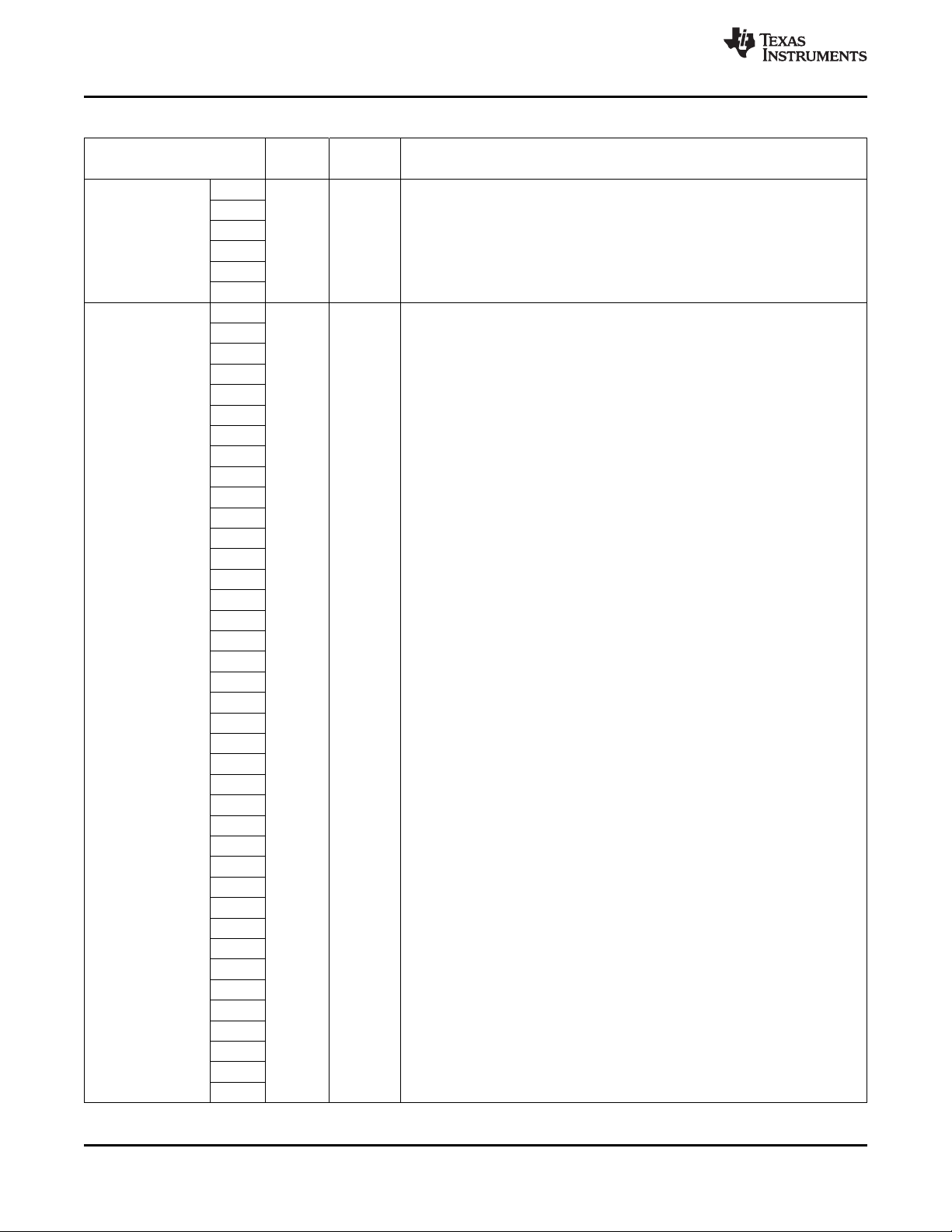
TMS320DM6467
SPRS403G–DECEMBER 2007–REVISED OCTOBER 2010
Table 3-31. Supply Terminal Functions (continued)
SIGNAL
NAME NO.
DV
DDR2
CV
DD
R18
T18
T19
U19
W21
AA20
G8
G9
G10
G11
G12
G13
G14
G15
H7
H8
H9
H14
H15
H16
J7
J8
J9
J10
J11
J13 S SmartReflex, see the Section 7.3.6, SmartReflex (Voltage Scaling).
J14
J15
J16
K8
K9
K10
K11
K13
K14
K15
K16
P7
P8
P9
P10
P11
P13
P14
P15
TYPE
S
(1)
OTHER DESCRIPTION
www.ti.com
1.8-V DDR2 I/O supply voltage
(see the Power-Supply Decoupling section of this data manual)
1.20-V core supply voltage (-594, -594A, -729 devices)
(see the Power-Supply Decoupling section of this data manual)
SmartReflex: when selected (VP_DOUT7/VADJEN = 1 at reset), the
GP[7]/CVDDADJ1 and GP[6]/CVDDADJ0 pins function as SmartReflex Control
Outputs to the adjustable core power supply. For more detailed information on
1.2-V core supply voltage (-594V, -594AV only) [GP[7]/CVDDADJ1 and
GP[6]/CVDDADJ0 = 00]
1.05-V core supply voltage (-594V, -594AV only) [GP[7]/CVDDADJ1 and
GP[6]/CVDDADJ0 = 11]
76 Device Overview Copyright © 2007–2010, Texas Instruments Incorporated
Submit Documentation Feedback
Product Folder Link(s): TMS320DM6467
Page 77

TMS320DM6467
www.ti.com
NAME NO.
CV
DD
SIGNAL
Table 3-31. Supply Terminal Functions (continued)
(1)
TYPE
R8
R9
R10
R11
R13
R14
R15
T8
T9
T10
T11
T13
T14
T15
U8
U9
U10 GP[6]/CVDDADJ0 = 00]
U14
U15
U16
V9
V10
V11
V12
V13
V14
V15
V16
S SmartReflex, see the Section 7.3.6, SmartReflex (Voltage Scaling).
OTHER DESCRIPTION
1.20-V core supply voltage (-594, -594A, -729 devices)
(see the Power-Supply Decoupling section of this data manual)
SmartReflex: when selected (VP_DOUT7/VADJEN = 1 at reset), the
GP[7]/CVDDADJ1 and GP[6]/CVDDADJ0 pins function as SmartReflex Control
Outputs to the adjustable core power supply. For more detailed information on
1.2-V core supply voltage (-594V, -594AV only) [GP[7]/CVDDADJ1 and
1.05-V core supply voltage (-594V, -594AV only) [GP[7]/CVDDADJ1 and
GP[6]/CVDDADJ0 = 11]
SPRS403G–DECEMBER 2007–REVISED OCTOBER 2010
Copyright © 2007–2010, Texas Instruments Incorporated Device Overview 77
Submit Documentation Feedback
Product Folder Link(s): TMS320DM6467
Page 78

TMS320DM6467
SPRS403G–DECEMBER 2007–REVISED OCTOBER 2010
3.7.28 Ground
Table 3-32. Ground Terminal Functions
SIGNAL
NAME NO.
A7
A14
A18
A21
B1
B19
B23
C19
D19
E19
E22
F6
F7
F19
G6
G18
H5
V
SS
(1) I = Input, O = Output, Z = High impedance, S = Supply voltage, GND = Ground, A = Analog signal
H10
H11
H12
H13
H18
H19
J5
J12
J18
K5
K12
K18
K22
L5
L6
L7
L8
L9
L10
(1)
TYPE
GND Ground pins
OTHER DESCRIPTION
GROUND PINS
www.ti.com
78 Device Overview Copyright © 2007–2010, Texas Instruments Incorporated
Submit Documentation Feedback
Product Folder Link(s): TMS320DM6467
Page 79

TMS320DM6467
www.ti.com
NAME NO.
V
SS
SIGNAL
L11
L12
L13
L14
L15
L16
L17
L18
M2
M5
M6
M7
M8
M9
M10
M11
M12
M13
M14
M15
M16
M17
M18
N5
N6
N7
N8
N9
N10
N11
N12
N13
N14
N15
N16
N17
N18
P6
P12
P16
P17
P18
P22
R6
R12
R16
SPRS403G–DECEMBER 2007–REVISED OCTOBER 2010
Table 3-32. Ground Terminal Functions (continued)
(1)
TYPE
GND Ground pins
OTHER DESCRIPTION
Copyright © 2007–2010, Texas Instruments Incorporated Device Overview 79
Submit Documentation Feedback
Product Folder Link(s): TMS320DM6467
Page 80

TMS320DM6467
SPRS403G–DECEMBER 2007–REVISED OCTOBER 2010
Table 3-32. Ground Terminal Functions (continued)
SIGNAL
NAME NO.
V
SS
T6
T12
T16
T17
U6
U11
U12
U13
U17
U18
V6
V18
V19
W19
W22
Y19
AB1
AB12
AB21
AB23
AC1
AC2
AC22
AC23
(1)
TYPE
GND Ground Pins
OTHER DESCRIPTION
www.ti.com
80 Device Overview Copyright © 2007–2010, Texas Instruments Incorporated
Submit Documentation Feedback
Product Folder Link(s): TMS320DM6467
Page 81

TMS320DM6467
www.ti.com
3.8 Device Support
3.8.1 Development Support
TI offers an extensive line of development tools for the TMS320DM646x DMSoC platform, including tools
to evaluate the performance of the processors, generate code, develop algorithm implementations, and
fully integrate and debug software and hardware modules. The tool's support documentation is
electronically available within the Code Composer Studio™ Integrated Development Environment (IDE).
The following products support development of TMS320DM646x SoC-based applications:
Software Development Tools:
Code Composer Studio™ Integrated Development Environment (IDE): including Editor
C/C++/Assembly Code Generation, and Debug plus additional development tools
Scalable, Real-Time Foundation Software (DSP/BIOS™), which provides the basic run-time target
software needed to support any SoC application.
Hardware Development Tools:
Extended Development System (XDS™) Emulator
For a complete listing of development-support tools for the TMS320DM644x DMSoC platform, visit the
Texas Instruments web site on the Worldwide Web at http://www.ti.com uniform resource locator
(URL). For information on pricing and availability, contact the nearest TI field sales office or authorized
distributor.
SPRS403G–DECEMBER 2007–REVISED OCTOBER 2010
3.8.2 Device and Development-Support Tool Nomenclature
To designate the stages in the product development cycle, TI assigns prefixes to the part numbers of all
DSP devices and support tools. Each DSP commercial family member has one of three prefixes: TMX,
TMP, or TMS (e.g.,TMX320DM6467ZUT). Texas Instruments recommends two of three possible prefix
designators for its support tools: TMDX and TMDS. These prefixes represent evolutionary stages of
product development from engineering prototypes (TMX/TMDX) through fully qualified production
devices/tools (TMS/TMDS).
Device development evolutionary flow:
TMX Experimental device that is not necessarily representative of the final device's electrical
specifications.
TMP Final silicon die that conforms to the device's electrical specifications but has not completed
quality and reliability verification.
TMS Fully-qualified production device.
Support tool development evolutionary flow:
TMDX Development-support product that has not yet completed Texas Instruments internal
qualification testing.
TMDS Fully qualified development-support product.
TMX and TMP devices and TMDX development-support tools are shipped against the following
disclaimer:
"Developmental product is intended for internal evaluation purposes."
TMS devices and TMDS development-support tools have been characterized fully, and the quality and
reliability of the device have been demonstrated fully. TI's standard warranty applies.
Copyright © 2007–2010, Texas Instruments Incorporated Device Overview 81
Submit Documentation Feedback
Product Folder Link(s): TMS320DM6467
Page 82

PREFIX
TMS
320 DM6467
ZUT
TMX = Experimental device
TMS = Qualified device
DEVICE FAMILY
320 = TMS320™ DSP family
PACKAGE TYPE
(A)
ZUT = 529-pin plastic BGA, with Pb-Free soldered balls
C64x+™ DSP:
DM6467
DEVICE
DEVICE SPEED RANGE
( )
Blank= 594-MHz DSP, 297-MHz ARM9 [Default]
7 =729-MHz DSP, 364.5-MHz ARM9
, 297-MHz DDR2
, 310.5-MHz DDR2
TEMPERATURE RANGE
AA
SILICON REVISION:
Blank = Revision 1.0
A = Revision 1.1
C = Revision 3.0
V
Blank=
A = -4
0° C to 85° C, Commercial Temperature
0° C to 105° C, Extended Temperature [-594 MHz only]
D = -40° C to 85° C, Industrial Temperature [-729 MHz only]
VOLTAGE SCALE ADJUSTMENT
Blank=
V = SmartReflex [-594 MHz only]
SmartReflex Not Supported
TMX
Blank = Revision 1.1
TMS
C = Revision 3.0
TMS320DM6467
SPRS403G–DECEMBER 2007–REVISED OCTOBER 2010
Predictions show that prototype devices (TMX or TMP) have a greater failure rate than the standard
production devices. Texas Instruments recommends that these devices not be used in any production
system because their expected end-use failure rate still is undefined. Only qualified production devices are
to be used.
TI device nomenclature also includes a suffix with the device family name. This suffix indicates the
package type (for example, ZUT), the temperature range (for example, "Blank" is the commercial
temperature range), and the device speed range in megahertz (for example, "Blank" is the default
[594-MHz DSP, 297-MHz ARM9]).
Figure 3-8 provides a legend for reading the complete device name for any TMS320DM646x DMSoC
platform member.
www.ti.com
82 Device Overview Copyright © 2007–2010, Texas Instruments Incorporated
A. BGA = Ball Grid Array
B. For actual device part numbers (P/Ns) and ordering information, see the TI website (http://www.ti.com).
(B)
Figure 3-8. Device Nomenclature
Submit Documentation Feedback
Product Folder Link(s): TMS320DM6467
Page 83

TMS320DM6467
www.ti.com
3.9 Documentation Support
3.9.1 Related Documentation From Texas Instruments
The following documents describe the TMS320DM646x Digital Media System-on-Chip (DMSoC). Copies
of these documents are available on the Internet at www.ti.com. Tip: Enter the literature number in the
search box provided at www.ti.com.
The current documentation that describes the DM646x DMSoC, related peripherals, and other technical
collateral, is available in the C6000 DSP product folder at: www.ti.com/c6000.
SPRUEP8 TMS320DM646x DMSoC DSP Subsystem Reference Guide. Describes the digital signal
processor (DSP) subsystem in the TMS320DM646x Digital Media System-on-Chip (DMSoC).
SPRUEP9 TMS320DM646x DMSoC ARM Subsystem Reference Guide. Describes the ARM
subsystem in the TMS320DM646x Digital Media System-on-Chip (DMSoC). The ARM
subsystem is designed to give the ARM926EJ-S (ARM9) master control of the device. In
general, the ARM is responsible for configuration and control of the device; including the
DSP subsystem and a majority of the peripherals and external memories.
SPRUEQ0 TMS320DM646x DMSoC Peripherals Overview Reference Guide. Provides an overview
and briefly describes the peripherals available on the TMS320DM646x Digital Media
System-on-Chip (DMSoC).
SPRAA84 TMS320C64x to TMS320C64x+ CPU Migration Guide. Describes migrating from the Texas
Instruments TMS320C64x digital signal processor (DSP) to the TMS320C64x+ DSP. The
objective of this document is to indicate differences between the two cores. Functionality in
the devices that is identical is not included.
SPRS403G–DECEMBER 2007–REVISED OCTOBER 2010
SPRU732 TMS320C64x/C64x+ DSP CPU and Instruction Set Reference Guide. Describes the CPU
architecture, pipeline, instruction set, and interrupts for the TMS320C64x and TMS320C64x+
digital signal processors (DSPs) of the TMS320C6000 DSP family. The C64x/C64x+ DSP
generation comprises fixed-point devices in the C6000 DSP platform. The C64x+ DSP is an
enhancement of the C64x DSP with added functionality and an expanded instruction set.
SPRU871 TMS320C64x+ DSP Megamodule Reference Guide. Describes the TMS320C64x+ digital
signal processor (DSP) megamodule. Included is a discussion on the internal direct memory
access (IDMA) controller, the interrupt controller, the power-down controller, memory
protection, bandwidth management, and the memory and cache.
SPRAAV0 Understanding TI's PCB Routing Rule-Based DDR Timing Specification Application
Report This application report describes the way the DDR high-speed timing requirements
are now going to be communicated to system designers. The system designer uses this
information to evaluate whether timing specifications are met and can be expected to
operate reliably.
SPRAAZ2 Enabling SmartReflex on the TMS320DM6467 Application Report This application report
describes the basic concepts of SmartReflex™ technology implemented in the DM6467
device. The goal for implementing this technology and the expected benefits are detailed,
and a reference design of the SmartReflex feature is introduced.
3.10 Community Resources
The following links connect to TI community resources. Linked contents are provided "AS IS" by the
respective contributors. They do not constitute TI specifications and do not necessarily reflect TI's views;
see TI's Terms of Use.
TI E2E Community TI's Engineer-to-Engineer (E2E) Community. Created to foster collaboration
among engineers. At e2e.ti.com, you can ask questions, share knowledge, explore ideas and
help solve problems with fellow engineers.
Copyright © 2007–2010, Texas Instruments Incorporated Device Overview 83
Submit Documentation Feedback
Product Folder Link(s): TMS320DM6467
Page 84

TMS320DM6467
SPRS403G–DECEMBER 2007–REVISED OCTOBER 2010
TI Embedded Processors Wiki Texas Instruments Embedded Processors Wiki. Established to help
developers get started with Embedded Processors from Texas Instruments and to foster
innovation and growth of general knowledge about the hardware and software surrounding
these devices.
www.ti.com
84 Device Overview Copyright © 2007–2010, Texas Instruments Incorporated
Submit Documentation Feedback
Product Folder Link(s): TMS320DM6467
Page 85

TMS320DM6467
www.ti.com
SPRS403G–DECEMBER 2007–REVISED OCTOBER 2010
4 Device Configurations
4.1 System Module Registers
The system module includes status and control registers for configuration of the device.Brief descriptions
of the various registers are shown in Table 4-1. System Module registers required for device
configurations are discussed in the following sections.
Table 4-1. System Module Register Memory Map
HEX ADDRESS RANGE REGISTER ACRONYM DESCRIPTION
0x01C4 0000 PINMUX0 Pin Multiplexing Control 0 (see Section 4.7.2.1, PINMUX0 Register).
0x01C4 0004 PINMUX1 Pin Multiplexing Control 1 (see Section 4.7.2.2, PINMUX1 Register).
0x01C4 0008 DSPBOOTADDR DSP Boot Address. Decoded by bootloader software for host boots.
0x01C4 000C SUSPSRC Emulator Suspend Source (see Section 4.7.3.13, Emulation Control).
0x01C4 0010 BOOTSTAT Boot Status (see Section 4.4.2.2, BOOTSTAT Register).
0x01C4 0014 BOOTCFG Device Boot Configuration (see Section 4.4.2.3, BOOTCFG Register).
0x01C4 0018 SMTREFLEX SmartReflex Status (see Figure 7-7, SMTREFLEX Status Register).
0x01C4 001C - 0x01C4 0020 – Reserved
0x01C4 0024 ARMBOOT ARM926 Boot Control (see Section 4.4.2.4, ARMBOOT Register).
0x01C4 0028 JTAGID Device ID Number [see Section 7.29.1, JTAG ID (JTAGID) Register
0x01C4 002C – Reserved
0x01C4 0030 HPICTL HPI Control (see Section 4.6.2.1, HPICTL Register).
0x01C4 0034 USBCTL USB Control (see Section 4.6.2.2, USBCTL Register).
0x01C4 0038 VIDCLKCTL Video Clock Control (see Section 4.3.2.1, Video Clock Control).
0x01C4 003C MSTPRI0 Bus Master Priority Control 0 (see Section 4.6.1, Switch Central
0x01C4 0040 MSTPRI1 Bus Master Priority Control 1 (see Section 4.6.1, Switch Central
0x01C4 0044 MSTPRI2 Bus Master Priority Control 2 (see Section 4.6.1, Switch Central
0x01C4 0048 VDD3P3V_PWDN VDD3.3-V I/O Powerdown Control (see Section 4.2, Power
0x01C4 004C – Reserved
0x01C4 0050 TSIFCTL TSIF Control Register (see Section 4.3.2.2, TSIF Control).
0x01C4 0054 PWMCTL PWM Control (see Section 4.6.2.3, PWM (Trigger Source) Control
0x01C4 0058 EDMATCCFG EDMA TC Configuration (see Section 4.6.2.4, EDMATCCFG
0x01C4 005C CLKCTL Oscillator and Output Clock Control (see Section 4.3.3, Clock and
0x01C4 0060 DSPINT ARM to DSP Interrupt Status (see Section 4.7.3.12, ARM/DSP
0x01C4 0064 DSPINTSET ARM to DSP Interrupt Set (see Section 4.7.3.12, ARM/DSP
0x01C4 0068 DSPINTCLR ARM to DSP Interrupt Clear (see Section 4.7.3.12, ARM/DSP
0x01C4 006C VSCLKDIS Video and TSIF Clock Disable (see Section 4.3.2.3, Video and TSIF
0x01C4 0070 ARMINT DSP to ARM Interrupt Status (see Section 4.7.3.12, ARM/DSP
0x01C4 0074 ARMINTSET DSP to ARM Interrupt Set (see Section 4.7.3.12, ARM/DSP
(See Section 4.4.2.1, DSPBOOTADDR Register.)
[Voltage Scale Adjustment (V) parts only]
Description(s)].
Resource (SCR) Bus Priorities).
Resource (SCR) Bus Priorities).
Resource (SCR) Bus Priorities).
Considerations).
Register).
Register).
Oscillator Control).
Communications Interrupts).
Communications Interrupts).
Communications Interrupts).
Clock Disable).
Communications Interrupts).
Communications Interrupts).
Copyright © 2007–2010, Texas Instruments Incorporated Device Configurations 85
Submit Documentation Feedback
Product Folder Link(s): TMS320DM6467
Page 86

TMS320DM6467
SPRS403G–DECEMBER 2007–REVISED OCTOBER 2010
www.ti.com
Table 4-1. System Module Register Memory Map (continued)
HEX ADDRESS RANGE REGISTER ACRONYM DESCRIPTION
0x01C4 0078 ARMINTCLR DSP to ARM Interrupt Clear (see Section 4.7.3.12, ARM/DSP
0x01C4 007C ARMWAIT ARM Memory Wait State Control (see Section 4.4.2.5, ARMWAIT
0x01C4 0080 - 0x01C4 03FF – Reserved
Communications Interrupts).
Register).
86 Device Configurations Copyright © 2007–2010, Texas Instruments Incorporated
Submit Documentation Feedback
Product Folder Link(s): TMS320DM6467
Page 87

TMS320DM6467
www.ti.com
4.2 Power Considerations
The DM6467 provides several means of managing power consumption.
As described in the Section 7.3.4, DM6467 Power and Clock Domains, the DM6467 has one single power
domain—the “Always On” power domain. Within this power domain, the DM6467 utilizes local clock gating
via the Power and Sleep Controller (PSC) to achieve power savings. For more details on the PSC, see
Section 7.3.5, Power and Sleep Controller (PSC) and the TMS320DM646x DMSoC ARM Subsystem
Reference Guide (literature number SPRUEP9).
Some of the DM6467 peripherals support additional power saving features. For more details on power
saving features supported, see the peripheral-specific reference guides [listed/linked in the
TMS320DM646x DMSoC Peripherals Overview Reference Guide (literature number SPRUEQ0).
Most DM6467 3.3-V I/Os can be powered-down to reduce power consumption. The VDD3P3V_PWDN
register in the System Module (see Figure 4-1 ) is used to selectively power down unused 3.3-V I/O pins.
Note: To save power, all other I/O buffers are powered down by default. Before using these pins, the user
must program the VDD3P3V_PWDN register to power up the corresponding I/O buffers.
For a list of multiplexed pins on the device and the pin mux group each pin belongs to, see Section 4.7.3,
Pin Multiplexing Details.
Note: The VDD3P3V_PWDN register only controls the power to the I/O buffers. The Power and Sleep
Controller (PSC) determines the clock/power state of the peripheral.
SPRS403G–DECEMBER 2007–REVISED OCTOBER 2010
31 29 28 27 26 25 24 23 22 21 20 19 18 17 16
RESERVED USBV CLKOUT RSV SPI VLYNQ RESERVED GMII MII MCASP1 MCASP0 PCIHPI1 PCIHPI0
R-000 R/W-1 R/W-0 R-0 R/W-1 R/W-1 R-00 R/W-1 R/W-1 R/W-1 R/W-1 R/W-0 R/W-0
15 14 13 12 11 10 9 8 7 6 5 4 3 2 1 0
GPIO WDTIM TIM23 TIM01 PWM1 PWM0 UR2FC UR2DAT UR1FC UR1DAT UR0MDM UR0DF VPIF3 VPIF2 VPIF1 VPIF0
R/W-0 R/W-0 R/W-1 R/W-1 R/W-1 R/W-1 R/W-1 R/W-1 R/W-1 R/W-1 R/W-1 R/W-1 R/W-1 R/W-0 R/W-1 R/W-1
LEGEND: R/W = Read/Write; R = Read only; -n = value after reset
Figure 4-1. VDD3P3V_PWDN Register [0x01C4 0048]
Copyright © 2007–2010, Texas Instruments Incorporated Device Configurations 87
Submit Documentation Feedback
Product Folder Link(s): TMS320DM6467
Page 88

TMS320DM6467
SPRS403G–DECEMBER 2007–REVISED OCTOBER 2010
Table 4-2. VDD3P3V_PWDN Register Bit Descriptions
BIT NAME DESCRIPTION
31:29 RESERVED Reserved. Read returns "0".
USB_DRVVBUS Powerdown Control.
28 USBV
27 CLKOUT
26 RSV Reserved. Read returns "0".
25 SPI This bit controls the six SPI interface pins: SPI_CLK, SPI_EN, SPI_CS0, SPI_CS1, SPI_SOMI, and
24 VLYNQ This bit controls the ten VLYNQ interface pins: VLYNQ_CLOCK, VLYNQ_SCRUN,
23:22 RESERVED Reserved. Read returns "0".
21 GMII This bit controls the ten pins used by GMII (Gigabit) only: RFTCLK, GMTCLK, MTXD[7:4], and
20 MII This bit controls the 17 pins used by (G)MII (10/100/1000) and MDIO interfaces: MTCLK,
19 MCASP1
18 MCASP0 This bit controls the 12 McASP0 pins: ACLKR0, AHCLKR0, AFSR0, ACLKX0, AHCLKX0, AFSX0,
17 PCIHPI1 PCI_CBE1/ATA_CS1/GP[32]/EM_A[19], PCI_CBE0/ATA_CS0/GP[33]/EM_A[18],
16 PCIHPI0
15 GPIO
14 WDTIM
13 TIM23
12 TIM01
11 PWM1
10 PWM0
9 UR2FC This bit controls the URTS2/UIRTX2/TS0_PSTIN/GP[41] and
0 = I/O cells powered up.
1 = I/O cells powered down.
This bit controls the USB_DRVVBUS/GP[22] pin.
CLKOUT0 Powerdown Control.
This bit controls the CLKOUT0 pin.
SPI Powerdown Control.
SPI_SIMO.
VLYNQ Powerdown Control.
VLYNQ_TXD[3:0], and VLYNQ_RXD[3:0].
GMII Powerdown Control.
MRXD[7:4].
MII Powerdown Control.
MTXD[3:0], MTXEN, MCOL, MCRS, MRCLK, MRXD[3:0], MRXDV, MRXER, MDCLK, and MDIO.
McASP1 Powerdown Control.
This bit controls the three McASP1 pins: ACLKX1, AHCLKX1, and AXR1[0].
McASP0 Powerdown Control.
AXR0[3:0], AMUTE0, and AMUTEIN0.
PCI/HPI/EMIFA/ATA Powerdown Control.
This bit controls the 28 pins used by the ATA or PCI`, HPI, or EMIFA. These pins include:
PCI_RST/DA2/GP[13]/EM_A[22], PCI_IDSEL/HDDIR/EM_R/W,
PCI_REQ/DMARQ/GP[11]/EM_CS5, PCI_GNT/DMACK/GP[12]/EM_CS4,
DIOW/GP[20]/EM_WAIT4/(RDY4/BSY4), IORDY/GP[21]/EM_WAIT3/(RDY3/BSY3),
DIOR/GP[19]/EM_WAIT5/(RDY5/BSY5), DA1/GP[16]/EM_A[21], DA0/GP[17]/EM_A[20],
INTRQ/GP[18]/RSV , PCI_AD[31:16]/DD[15:0]/HD[31:16]/EM_A[15:0]
Defaults to powered up for NOR boot.
PCI/HPI/EMIFA Powerdown Control.
This bit controls the 28 pins used by PCI, HPI, or EMIFA but not shared with ATA. These pins
include: PCI_CLK/GP[10], PCI_DEVSEL/HCNTL1/EM_BA[1], PCI_FRAME/HINT/EM_BA[0],
PCI_IRDY/HRDY/EM_A[17]/(CLE), PCI_TRDY/HHWIL/EM_A[16]/(ALE),
PCI_STOP/HCNTL0/EM_WE, PCI_SERR/HDS1/EM_OE, PCI_PERR/HCS/EM_DQM1,
PCI_PAR/HAS/EM_DQM0, PCI_INTA/EM_WAIT2/(RDY2/BSY2), PCI_CBE3/HR/W/EM_CS3,
PCI_CBE2/HDS2/EM_CS2, PCI_AD[15:0]/HD[15:0]/EM_D[15:0]
Defaults to powered up for NOR boot.
GPIO Powerdown Control.
This bit controls the eight GP[7:0] pins. Defaults to powered up.
WD Timer Powerdown Control.
This bit controls the WD Timer pin TOUT2.
Timer1 Powerdown Control.
This bit controls the three Timer1 pins TINP1L, TOUT1L, and TOUT1U.
Timer0 Powerdown Control.
This bit controls the four Timer0 pins TINP0L, TINP0U, TOUT0L, and TOUT0U.
PWM1 Powerdown Control.
This bit controls the PWM1/TS1_DOUT pin.
PWM0 Powerdown Control.
This bit controls the PWM0/CRG0_PO/TS1_ENAO pin.
UART2 Flow Control Powerdown Control.
UCTS2/USD2/CRG0_VCXI/GP[42]/TS1_PSTO pins.
www.ti.com
88 Device Configurations Copyright © 2007–2010, Texas Instruments Incorporated
Submit Documentation Feedback
Product Folder Link(s): TMS320DM6467
Page 89

TMS320DM6467
www.ti.com
Table 4-2. VDD3P3V_PWDN Register Bit Descriptions (continued)
BIT NAME DESCRIPTION
8 UR2DAT This bit controls the URXD2/CRG1_VCXI/GP[39]/CRG0_VCXI and
7 UR1FC This bit controls the URTS1/UIRTX1/TS0_WAITO/GP[25] and
6 UR1DAT
5 UR0MDM This bit controls the UDTR0/TS0_ENAO/GP[36], UDSR0/TS0_PSTO/GP[37],
4 UR0DF This bit controls the URXD0/TS1_DIN, UTXD0/URCTX0/TS1_PSTIN,
3 VPIF3 This bit controls the VP_DOUT[15:8]/TS1_xx, VP_CLKIN3/TS1_CLKO, and VP_CLKO3/TS0_CLKO
2 VPIF2 This bit controls the VP_DOUT[7:0], VP_CLKIN2, and VP_CLKO2 pins. (VP_DOUT[7:0] are boot
1 VPIF1
0 VPIF0 This bit controls the VP_DIN[3:0]/TS0_DOUT[3:0], VP_DIN[7:4]/TS0_DOUT[7:4]/TS1_xx, and
UART2 Data Powerdown Control.
UTXD2/URCTX2/CRG1_PO/GP[40]/CRG0_PO pins.
UART1 Flow Control Powerdown Control.
UCTS1/USD1/TS0_EN_WAITO/GP[26] pins.
UART1 Data Powerdown Control.
This bit controls the URXD1/TS0_DIN7/GP[23] and UTXD1/URCTX1/TS0_DOUT7/GP[24] pins.
UART0 Modem Control Powerdown Control.
UDCD0/TS0_WAITIN/GP[38], and URIN0/GP[8]/TS1_WAITIN pins.
UART0 Data and Flow Control Powerdown Control.
URTS0/UIRTX0/TS1_EN_WAITO, and UCTS0/USD0 pins.
VPIF MSB Output Powerdown Control.
pins.
VPIF LSB Output Powerdown Control.
configuration inputs.)
VPIF MSB Input Powerdown Control.
This bit controls the VP_DIN[15:8]/TS0_DIN[7:0] and VP_CLKIN1 pins.
VPIF LSB Input Powerdown Control.
VP_CLKIN0 pins.
SPRS403G–DECEMBER 2007–REVISED OCTOBER 2010
Copyright © 2007–2010, Texas Instruments Incorporated Device Configurations 89
Submit Documentation Feedback
Product Folder Link(s): TMS320DM6467
Page 90

TMS320DM6467
SPRS403G–DECEMBER 2007–REVISED OCTOBER 2010
4.3 Clock Considerations
Global device and local peripheral clocks are controlled by the PLL Controllers (PLLC1 and PLLC2) and
the Power and Sleep Controller (PSC). In addition, the System Module Video Clock Control (VIDCLKCTL),
TSIF Control (TSIFCTL), and Clock and Oscillator Control (CLKCTL) registers configure the clock sources
to the VPIF, TSIF, CRGEN peripherals, and the Auxiliary Oscillator.
The selected Video, TSIF, and CRGEN module input clocks are disabled using the System Module Video
Source Clock Disable (VSCLKDIS) register. Note: To ensure glitch-free operation, the clock should be
disabled before changing the clock source frequency or muxing via the VIDCLKCTL and TSIFCTL.
4.3.1 Clock Configurations after Device Reset
After device reset, the user is responsible for programming the PLL Controllers (PLLC1 and PLLC2) and
the Power and Sleep Controller (PSC) to bring the device up to the desired clock frequency and the
desired peripheral clock state (clock gating or not).
For additional power savings, some of the DM6467 peripherals support clock gating within the peripheral
boundary. For more details on clock gating and power saving features supported by a specific peripheral,
see the peripheral-specific reference/user's guides [listed/linked in the TMS320DM646x DMSoC
Peripherals Overview Reference Guide (literature number SPRUEQ0)].
4.3.1.1 Device Clock Frequency
The DM6467 defaults to PLL bypass mode. If the ROM bootloader is selected (BTMODE[3:0] ≠ 0100), the
bootloader code programs PLLC1 and PLLC2.
www.ti.com
Section 4.4.1, Boot Modes discusses the different boot modes in more detail.
The user must adhere to the various clock requirements when programming the PLLC1 and PLLC2:
• PLL multiplier and frequency ranges. For more details on PLL multiplier and frequency ranges, see
Section 7.5.1, PLL1 and PLL2.
4.3.1.2 Module Clock State
The clock and reset state for each of the modules is controlled by the Power and Sleep Controller (PSC).
Table 4-3 shows the default state of each module after a device-level global reset. The DM6467 device
has four different module states—Enable, Disable, SyncReset, or SwRstDisable. For more information on
the definitions of the module states, the PSC, and PSC programming, see Section 7.3.5, Power and Sleep
Controller (PSC) and the TMS320DM646x DMSoC ARM Subsystem Reference Guide (literature number
SPRUEP9).
90 Device Configurations Copyright © 2007–2010, Texas Instruments Incorporated
Submit Documentation Feedback
Product Folder Link(s): TMS320DM6467
Page 91
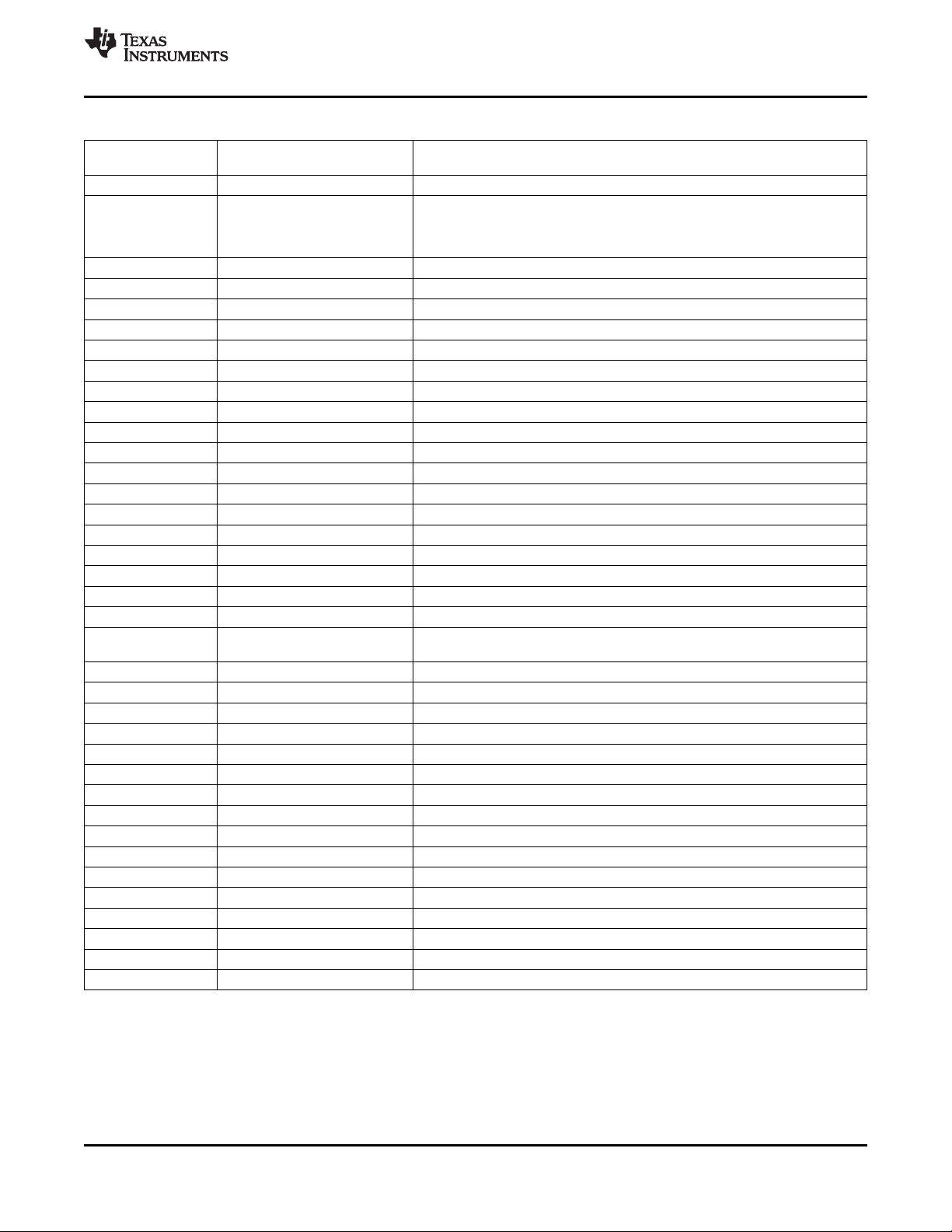
TMS320DM6467
www.ti.com
SPRS403G–DECEMBER 2007–REVISED OCTOBER 2010
Table 4-3. DM6467 Default Module States
LPSC # MODULE NAME
0 ARM Enable
DSP C64x+ If DSPBOOT = 0 then, Enable and Module Local Reset is asserted
1
2 HDVICP0 SwRstDisable
3 HDVICP1 SwRstDisable
4 EDMACC SwRstDisable
5 EDMATC0 SwRstDisable
6 EDMATC1 SwRstDisable
7 EDMATC2 SwRstDisable
8 EDMATC3 SwRstDisable
9 USB2.0 SwRstDisable
10 ATA SwRstDisable
11 VLYNQ SwRstDisable
12 HPI SwRstDisable
13 PCI SwRstDisable
14 EMAC/MDIO SwRstDisable
15 VDCE SwRstDisable
16 – 17 Video Port
18 TSIF0 SwRstDisable
19 TSIF1 SwRstDisable
20 DDR2 Memory Contoller SwRstDisable
21 EMIFA
22 McASP0 SwRstDisable
23 McASP1 SwRstDisable
24 CRGEN0 SwRstDisable
25 CRGEN1 SwRstDisable
26 UART0 SwRstDisable
27 UART1 SwRstDisable
28 UART2 SwRstDisable
29 PWM0 SwRstDisable
30 PWM1 SwRstDisable
31 I2C SwRstDisable
32 SPI SwRstDisable
33 GPIO SwRstDisable
34 TIMER0 SwRstDisable
35 TIMER1 SwRstDisable
36 – 44 Reserved Reserved
45 ARM INTC Enable
(1) The Video Port Module has a total of five clock inputs that can be controlled by the LPSC. One LPSC can support only a maximum of
four clocks; therefore, two LPSCs are assigned to the Video Port. Both Video Port LPSCs should be controlled together and should be
set to the same state.
(1)
(MDSTATn.LRST = 0).
If DSPBOOT = 1 then, Enable and Module Local Reset is deasserted
(MDSTATn.LRST = 1).
SwRstDisable
If BTMODE[3:0] ≠ 0100 and DSPBOOT = 0 then, SwRstDisable
If BTMODE[3:0] = 0100 or DSPBOOT = 1 then, Enable
DEFAULT MODULE STATE
[PSC Register MDSTATn.STATE]
Copyright © 2007–2010, Texas Instruments Incorporated Device Configurations 91
Submit Documentation Feedback
Product Folder Link(s): TMS320DM6467
Page 92
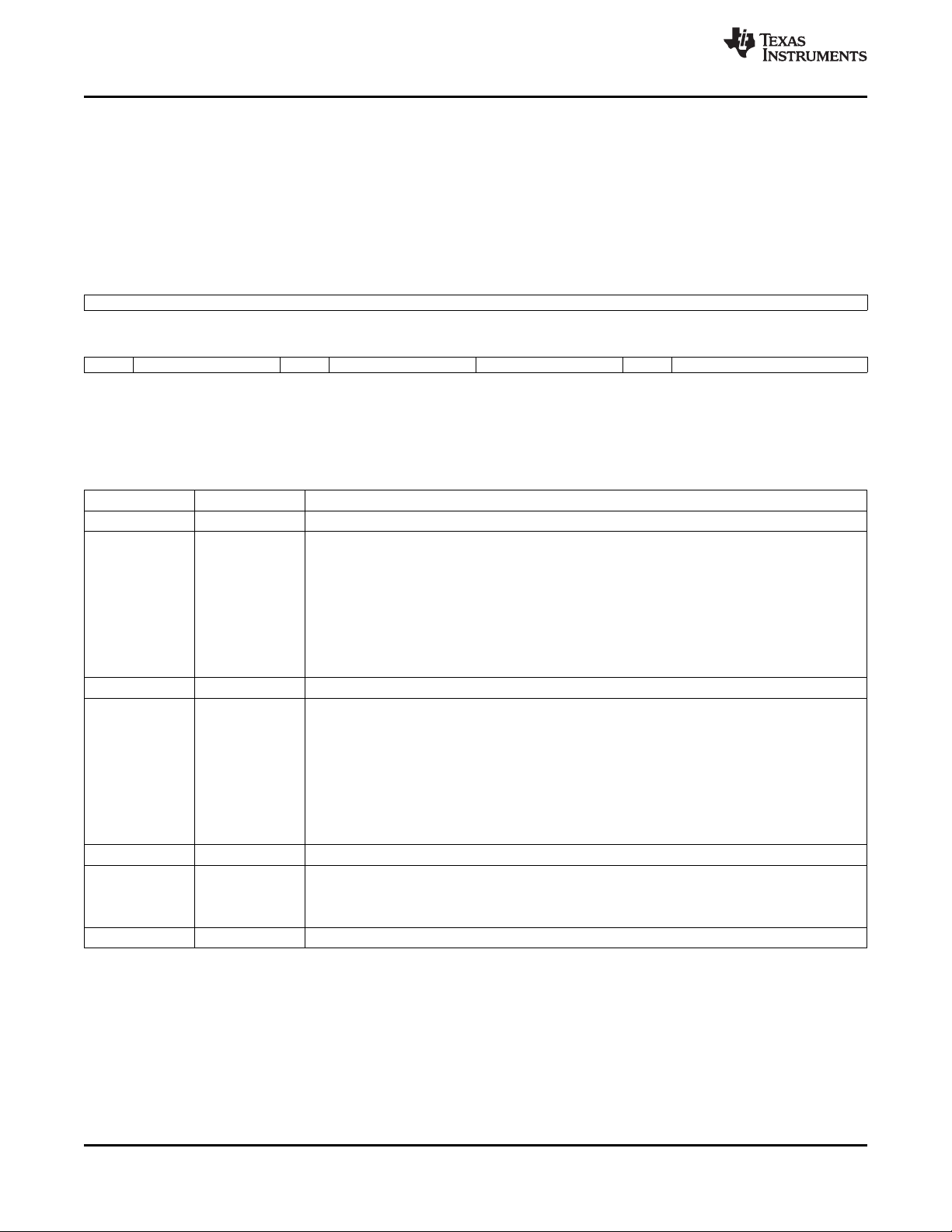
TMS320DM6467
SPRS403G–DECEMBER 2007–REVISED OCTOBER 2010
www.ti.com
4.3.2 Clock Control
This section describes the following registers: the VPIF (Video)/TSIF clock control and clock disable
registers and the Clock and Oscillator control register.
4.3.2.1 Video Clock Control Register
The Video Clock Control (VIDCLKCTL) register allows the user to select/control the clock muxing for the
video channels' (i.e., channels 1, 2, and 3) output clock source.
31 16
RESERVED
R-0000 0000 0000 0000
15 14 12 11 10 8 7 5 4 3 0
RSV VCH3CLK RSV VCH2CLK RESERVED VCH1CLK RESERVED
R-0 R/W-111 R-0 R/W-110 R-000 R/W-1 R-0000
LEGEND: R/W = Read/Write; R = Read only; -n = value after reset
Figure 4-2. VIDCLKCTL Register [0x01C4 0038]
Table 4-4. VIDCLKCTL Register Bit Descriptions
BIT NAME DESCRIPTION
31:15 RESERVED Reserved. Read returns "0".
Video Channel 3 Clock Source.
This field selects the clock source for the Channel 3 output source clock.
000 = CRG0_VCXI (external pin)
001 = CRG1_VCXI (external pin)
14:12 VCH3CLK
11 RSV Reserved. Read returns "0".
10:8 VCH2CLK
7:5 RESERVED Reserved. Read returns "0".
4 VCH1CLK
3:0 RESERVED Reserved. Read returns "0".
010 = SYSCLK8 (PLLC1)
011 = AUXCLK (PLLC1)
100 = VP_CLKIN0 (external pin)
101 = STC_CLKIN (external pin)
110 = VP_CLKIN2 (external pin)
111 = VP_CLKIN3 (external pin)
Video Channel 2 Clock Source.
This field selects the clock source for the Channel 2 output source clock.
000 = CRG0_VCXI (external pin)
001 = CRG1_VCXI (external pin)
010 = SYSCLK8 (PLLC1)
011 = AUXCLK (PLLC1)
100 = VP_CLKIN0 (external pin)
101 = STC_CLKIN (external pin)
110 = VP_CLKIN2 (external pin)
111 = Reserved
Video Channel 1 Clock Source.
This bit selects the clock source for the Channel 1 input clock.
0 = VP_CLKIN0 (external pin)
1 = VP_CLKIN1 (external pin)
92 Device Configurations Copyright © 2007–2010, Texas Instruments Incorporated
Submit Documentation Feedback
Product Folder Link(s): TMS320DM6467
Page 93

TMS320DM6467
www.ti.com
SPRS403G–DECEMBER 2007–REVISED OCTOBER 2010
4.3.2.2 TSIF Control
The TSIF Control (TSIFCTL) registers allows the user to select/control the clock muxing for the counter
and serial output of TSIF1 andthe counter and parallel/serial output for TSIF0.
31 16
RESERVED
R-0000 0000 0000 0000
15 14 12 11 8 7 6 4 3 2 0
RSV TSIF1_CNTCLK TSSO_CLK RSV TSIF0_CNTCLK RSV TSPO_CLK
R-0 R/W-000 R/W-0000 R-0 R/W-000 R-0 R/W-000
LEGEND: R/W = Read/Write; R = Read only; -n = value after reset
Figure 4-3. TSIFCTL Register [0x01C4 0050]
Table 4-5. TSIFCTL Register Bit Descriptions
BIT NAME DESCRIPTION
31:15 RESERVED Reserved. Read returns "0".
TSIF1 Counter Clock Source.
This field selects the clock source for the TSIF1 module's counter.
000 = CRG1_VCXI (external pin)
001 = STC_CLKIN (external pin)
14:12 TSIF1_CNTCLK
11:8 TSSO_CLK 0100 = VP_CLKIN0 (external pin)
7 RSV Reserved. Read returns "0".
6:4 TSIF0_CNTCLK
3 RSV Reserved. Read returns "0".
2:0 TSPO_CLK
010 = AUXCLK (PLLC1 output – 27 MHz)
011 = CRG0_VCXI (external pin)
100 = VP_CLKIN2 (external pin)
101 = VP_CLKIN3 (external pin)
110 = Reserved
111 = Reserved
TSIF1 Serial Output Clock Source.
This field selects the clock source for the TSIF1 output source clock.
0000 = CRG1_VCXI (external pin)
0001 = STC_CLKIN (external pin)
0010 = SYSCLK6 (PLLC1)
0011 = SYSCLKBP (PLLC1)
0101 = TS1_CLKIN (external pin)
0110 = VP_CLKIN2 (external pin)
0111 = Reserved
1000 = CRG0_VCXI
1001 = Reserved
1xx1 = Reserved
TSIF0 Counter Clock Source.
This field selects the clock source for the TSIF0 module's counter.
000 = CRG0_VCXI (external pin)
001 = STC_CLKIN (external pin)
010 = AUXCLK (PLLC1 output – 27 MHz)
011 = CRG1_VCXI (external pin)
100 = VP_CLKIN0 (external pin)
101 = VP_CLKIN1 (external pin)
110 = Reserved
111 = Reserved
TSIF0 Parallel/Serial Output Clock Source.
This field selects the clock source for the TSIF0 output source clock.
000 = CRG0_VCXI (external pin)
001 = STC_CLKIN (external pin)
010 = SYSCLK5 (PLLC1)
011 = SYSCLKBP (PLLC1)
100 = VP_CLKIN0 (external pin)
101 = VP_CLKIN1 (external pin)
110 = TS0_CLKIN (external pin)
111 = CRG1_VCXI (external pin)
Copyright © 2007–2010, Texas Instruments Incorporated Device Configurations 93
Submit Documentation Feedback
Product Folder Link(s): TMS320DM6467
Page 94

TMS320DM6467
SPRS403G–DECEMBER 2007–REVISED OCTOBER 2010
www.ti.com
4.3.2.3 Video and TSIF Clock Disable
The Video Source Clock Disable (VSCLKDIS) register allows the user to disable the selected Video
(VPIF), TSIF, and CRGEN module input clocks.
Note: To ensure glitch-free operation, the clock should be disabled before changing the clock source
frequency or muxing via the VIDCLKCTL and TSIFCTL.
31 16
RESERVED
R-0000 0000 0000 0000
15 12 11 10 9 8 7 6 5 4 3 2 1 0
RESERVED VID3 VID2 VID1 VID0 TSIFCNT1 TSIFCNT0 TSIFTX1 TSIFTX0 TSIFRX1 TSIFRX0 CRG1 CRG0
R-0000 R/W-1 R/W-1 R/W-1 R/W-1 R/W-1 R/W-1 R/W-1 R/W-1 R/W-1 R/W-1 R/W-1 R/W-1
LEGEND: R/W = Read/Write; R = Read only; -n = value after reset
Figure 4-4. VSCLKDIS Register [0x01C4 006C]
Table 4-6. VSCLKDIS Register Bit Descriptions
BIT NAME DESCRIPTION
31:12 RESERVED Reserved. Read returns "0".
11 VID3 0 = Clock enabled.
10 VID2 0 = Clock enabled.
9 VID1 0 = Clock enabled.
8 VID0 0 = Clock enabled.
7 TSIFCNT1 0 = Clock enabled.
6 TSIFCNT0 0 = Clock enabled.
5 TSIFTX1 0 = Clock enabled.
4 TSIFTX0 0 = Clock enabled.
3 TSIFRX1 0 = Clock enabled.
2 TSIFRX0 0 = Clock enabled.
1 CRG1 0 = Clock enabled.
0 CRG0 0 = Clock enabled.
VPIF Channel 3 Clock Disable.
1 = Clock disabled.
VPIF Channel 2 Clock Disable.
1 = Clock disabled.
VPIF Channel 1 Clock Disable.
1 = Clock disabled.
VPIF Channel 0 Clock Disable.
1 = Clock disabled.
TSIF1 Counter Clock Disable.
1 = Clock disabled.
TSIF0 Counter Clock Disable.
1 = Clock disabled.
TSIF1 Transmit Clock Disable.
1 = Clock disabled.
TSIF0 Transmit Clock Disable.
1 = Clock disabled.
TSIF1 Receive Clock Disable.
1 = Clock disabled.
TSIF0 Receive Clock Disable.
1 = Clock disabled.
CRGEN1 Clock Disable.
1 = Clock disabled.
CRGEN0 Clock Disable.
1 = Clock disabled.
94 Device Configurations Copyright © 2007–2010, Texas Instruments Incorporated
Submit Documentation Feedback
Product Folder Link(s): TMS320DM6467
Page 95

TMS320DM6467
www.ti.com
SPRS403G–DECEMBER 2007–REVISED OCTOBER 2010
4.3.3 Clock and Oscillator Control
The Clock and Oscillator Control (CLKCTL) register allows the user to disable the OSC pwrdwn and pwr
disable
31 26 25 24 23 20 19 16
RESERVED OSCPWRDN OSCDIS RESERVED CLKOUT
R-0000 00 R/W-0 R/W-1 R-0000 R/W-1000
15 12 11 8 7 4 3 0
RESERVED AUD_CLK1 RESERVED AUD_CLK0
R-0000 R/W-0000 R-0000 R/W-0000
LEGEND: R/W = Read/Write; R = Read only; -n = value after reset
Figure 4-5. CLKCTL Register [0x01C4 005C]
Table 4-7. CLKCTL Register Bit Descriptions
BIT NAME DESCRIPTION
31:26 RESERVED Reserved. Read returns "0".
25 OSCPWRDN Auxiliary Oscillator Powerdown.
24 OSCDIS Auxiliary Oscillator Disable.
23:20 RESERVED Reserved. Read returns "0".
19:16 CLKOUT CLKOUT0 Source.
15:12 RESERVED Reserved. Read returns "0".
This bit controls the internal bias resistor conection.
0 = Internal bias resistor connected (normal operation)
1 = Internal bias resistor disconnected (external bias resistor required or clock input used)
This bit disables the oscillator.
0 = Oscillator enabled (normal operation).
1 = Oscillator disabled (clock input used or no Auxiliary clock required).
This field selects the clock source for the CLKOUT0 output.
0000 = Disabled
0001 = PLL1 AUXCLK
0010 = Reserved
0011 = SYSCLK3
0100 = SYSCLK4
0101 = SYSCLK5
0110 = SYSCLK6
0111 = Reserved
1000 = SYSCLK8
1001 = SYSCLK9
1010 = AUX_MXI
1011 = Reserved
1100 = Reserved
1101 = Reserved
1110 = Reserved
1111 = Reserved
(1)
(1) The maximum frequency allowed for the CLKOUT0 pin is 148.5 MHz. For the -729 MHz device, in PLL mode, do not configure the
CLKOUT bits to SYSCLK3 (0011) because the CLKOUT0 source will exceed the maximum frequency limit allowed for CLKOUT0 pin.
For more details on the CLKOUT0 timings, see Table 7-15, Switching Characteristics Over Recommended Operating Conditions for
CLKOUT0.
Copyright © 2007–2010, Texas Instruments Incorporated Device Configurations 95
Submit Documentation Feedback
Product Folder Link(s): TMS320DM6467
Page 96

TMS320DM6467
SPRS403G–DECEMBER 2007–REVISED OCTOBER 2010
Table 4-7. CLKCTL Register Bit Descriptions (continued)
BIT NAME DESCRIPTION
11:8 AUD_CLK1 AUDIO_CLK1 Source.
This field selects the clock source for the AUDIO_CLK1 output.
0000 = Disabled
0001 = PLL1 AUXCLK
0010 = CRG0_VCXI
0011 = CRG1_VCXI
0100 = VP_CLKIN0
0101 = VP_CLKIN1
0110 = VP_CLKIN2
0111 = VP_CLKIN3
1000 = AUX_MXI
1001 = STC_CLKIN
1010 = Reserved
1011 = Reserved
1100 = Reserved
1101 = Reserved
1110 = Reserved
1111 = Reserved
7:4 RESERVED Reserved. Read returns "0".
3:0 AUD_CLK0 AUDIO_CLK0 Source.
This field selects the clock source for the AUDIO_CLK0 output.
0000 = Disabled
0001 = PLL1 AUXCLK
0010 = CRG0_VCXI
0011 = CRG1_VCXI
0100 = VP_CLKIN0
0101 = VP_CLKIN1
0110 = VP_CLKIN2
0111 = VP_CLKIN3
1000 = AUX_MXI
1001 = STC_CLKIN
1010 = Reserved
1011 = Reserved
1100 = Reserved
1101 = Reserved
1110 = Reserved
1111 = Reserved
www.ti.com
96 Device Configurations Copyright © 2007–2010, Texas Instruments Incorporated
Submit Documentation Feedback
Product Folder Link(s): TMS320DM6467
Page 97

TMS320DM6467
www.ti.com
4.4 Boot Sequence
The boot sequence is a process by which the device's memory is loaded with program and data sections,
and by which some of the device's internal registers are programmed with predetermined values. The boot
sequence is started automatically after each device-level global reset. For more details on device-level
global resets, see Section 7.7, Reset.
There are several methods by which the memory and register initialization can take place. Each of these
methods is referred to as a boot mode. The boot mode to be used is selected at reset. For more
information on the bootmode selections, see Section 4.4.1, Boot Modes.
The device is booted through multiple means—primary bootloaders within internal ROM or EMIFA, and
secondary user bootloaders from peripherals or external memories. Boot modes, pin configurations, and
register configurations required for booting the device, are described in the following subsections.
4.4.1 Boot Modes
The DM6467 boot modes are determined by these device boot and configuration pins. For information on
how these pins are sampled at device reset, see Section 7.7.1.2, Latching Boot and Configuration Pins.
• BTMODE[3:0]
• PCIEN
• CS2BW
• DSPBOOT
• VP_DOUT7/VADJEN
SPRS403G–DECEMBER 2007–REVISED OCTOBER 2010
The TMS320DM646x DMSoC ARM can boot either from asynchronous EMIF/NOR Flash or from ARM
ROM, as determined by the device boot and configuration pins at reset (BTMODE[3:0] and PCIEN). The
PCIEN pin configuration is used to select the default configuration of the EMIFA/PCI/HPI pins at reset.
This allows the DM646x DMSoC to be PCI-compliant at reset. When PCIEN = 1, the PCI module controls
the multiplexed pins with the appropriate pullup/pulldown configuration. For all other bootmodes (non-PCI
bootmodes), the PCIEN must be cleared to "0".
For a more detailed description of the ROM boot modes supported by the DM646x DMSoC, see Using the
TMS320DM646x Bootloader Application Report (literature number SPRAAS0).
4.4.2 Boot Mode Registers
The DSPBOOTADDR, BOOTCMPLT, BOOTCMD, and BOOTCFG registers are used to control boot and
device configurations.
4.4.2.1 DSPBOOTADDR Register
The DSPBOOTADDR register contains the upper 22 bits of the DSP reset vector.
31 10 9 0
BOOTADDR[21:0] RESERVED
R/W-0100 0010 0010 0000 0000 00 R-00 0000 0000
LEGEND: R/W = Read/Write; R = Read only; -n = value after reset
Figure 4-6. DSPBOOTADDR Register
Table 4-8. DSPBOOTADDR Register Bit Descriptions
BIT NAME DESCRIPTION
31:10 BOOTADDR[21:0] Upper 22 bits of the C64x+ DSP boot address.
9:0 RESERVED Reserved
Copyright © 2007–2010, Texas Instruments Incorporated Device Configurations 97
Submit Documentation Feedback
Product Folder Link(s): TMS320DM6467
Page 98

TMS320DM6467
SPRS403G–DECEMBER 2007–REVISED OCTOBER 2010
4.4.2.2 BOOTSTAT Register
The Boot Status (BOOTSTAT) register indicates the status of the device boot process (e.g., boot error,
boot complete, or watchdog timer reset).
31 30 20 19 16
WDRST RESERVED BOOTERR
R/W-0 R-000 0000 0000 R-0000
15 1 0
RESERVED BC
R-0000 0000 0000 000 R/W-0
LEGEND: R/W = Read/Write; R = Read only; -n = value after reset
Figure 4-7. BOOTSTAT Register
Table 4-9. BOOTSTAT Register Bit Descriptions
BIT NAME DESCRIPTION
Watchdog Timer Reset.
0 = Device reset was not a result of a watchdog timer timeout.
31 WDRST This is a "sticky" bit that can be used to debug WD timeout conditions. The bit is set when a WD
30:20 RESERVED Reserved. Read returns "0".
19:16 BOOTERR
15:1 RESERVED Reserved. Read returns "0".
0 BC
1 = Device reset was a result of a watchdog timer timeout.
timeout occurs (TOUT2). This bit is reset (to "0") by a POR reset only; otherwise it retains its value.
It is not cleared by a Warm Reset or Soft Reset.
The bit may be cleared by writing a "1".
Boot Error.
0000 = No boot error [default].
Others = Bootloader detected boot error.
The exact meaning of the various error codes will be determined by the bootloader software.
Boot Complete.
0 = Host has not completed the boot sequence [default].
1 = Host has completed the boot sequence.
This bit may be optionally set by a host boot device (such as PCI or HPI) to indicate that it has
finished loading code. The ARM926 can poll this bit to determine whether to continue the boot
process.
www.ti.com
98 Device Configurations Copyright © 2007–2010, Texas Instruments Incorporated
Submit Documentation Feedback
Product Folder Link(s): TMS320DM6467
Page 99

TMS320DM6467
www.ti.com
SPRS403G–DECEMBER 2007–REVISED OCTOBER 2010
4.4.2.3 BOOTCFG Register
The Boot Configuration (BOOTCFG) register is a read-only register that indicates the value of the device
bootmode and configuration pins latched at the end of reset. During a hard reset (POR or RESET pin
active [low]), the values of the CFG pins (i.e., BTMODE[3:0], CS2BW, PCIEN, DSPBOOT) are propagated
through the BOOTCFG register to the Boot Controller. When RESET or POR is de-asserted, the value of
the pins is latched. The BOOTCFG value does not change as a result of a soft reset, instead the value
latched at the end of the previous global reset is retained.
31 18 17 16
RESERVED DSP_BT PCIEN
R-0000 0000 0000 00 R-L R-L
15 13 12 11 9 8 7 4 3 0
RESERVED VADJEN RESERVED CS2_BW RESERVED BOOTMODE
R-000 R-L R-000 R-L R-0000 R-LLLL
LEGEND: R = Read only; L = Latched pin value; -n = value after reset
Figure 4-8. BOOTCFG Register
Copyright © 2007–2010, Texas Instruments Incorporated Device Configurations 99
Submit Documentation Feedback
Product Folder Link(s): TMS320DM6467
Page 100

TMS320DM6467
SPRS403G–DECEMBER 2007–REVISED OCTOBER 2010
Table 4-10. BOOTCFG Register Bit Descriptions
BIT NAME DESCRIPTION
31:18 RESERVED Reserved. Read returns "0".
DSP Boot. Latched from DSPBOOT input at the rising edge of RESET or POR.
0 = ARM boots C64x+.
17 DSP_BT
16 PCIEN 1 = PCI enabled.
15:13 RESERVED Reserved. Read returns "0".
12 VADJEN SmartReflex control output pins.
11:9 RESERVED Reserved. Read returns "0".
8 CS2_BW
7:4 RESERVED Reserved. Read returns "0".
3:0 BOOTMODE 0110 = I2C boot.
1 = C64x+ self-boots.
This bit will cause the DSP to be released from reset automatically. The C64x+ will boot from
EMIFA (default DSPBOOTADDR address 0x4220 0000). If BOOTMODE = 0010 or 0011,
or PCIEN = 1, then the C64x+ self-boot will fail since EMIFA will be disabled.
PCI Enable. Latched from PCIEN input at the rising edge of RESET or POR.
0 = PCI disabled.
PCIEN = 1 disables the internal pullup and pulldown resistors on the PCI pins and configures the
pin muxing for PCI.
Votlage Adjust Enable (SmartReflex). Latched from VADJEN input at the rising edge of RESET or
POR.
This pin determines whether GP[6]/CVDDADJ0 and GP[7]/CVDDADJ1 function as GPIO pins or as
0 = SmartReflex outputs disabled. GP[6]/CVDDADJ0 and GP[7]/CVDDADJ1 pins function as GPIO.
1 = SmartReflex outputs enabled. GP[6]/CVDDADJ0 and GP[7]/CVDDADJ1 pins function as
SmartReflex control outputs.
EMIFA EM_CS2 Default Bus Width. Latched from CS2BW input at the rising edge of RESET or
POR.
0 = Default to 8-bit operation.
1 = Default to 16-bit operation.
This bit determines the default bus width of the EMIFA EM_CS2 memory space. This ensures that
boot from EMIFA (ARM or DSP) will correctly read the attached memory.
Boot Mode Configuration Bits. Bit values latched from BTMODE[3:0] at the rising edge of RESET or
POR.
0000 = Emulation boot.
0001 = Reserved.
0010 = HPI-16 (if PCIEN = 0).
PCI without autoinitialization (if PCIEN = 1).
0011 = HPI-32 (if PCIEN = 0).
PCI with autoinitialization (if PCIEN = 1).
0100 = EMIFA direct boot (ROM/NOR) (if PCIEN = 0; error if PCIEN = 1 defaults to UART0).
0101 = Reserved.
0111 = NAND Flash boot (if PCIEN = 0; error if PCIEN = 1 defaults to UART0).
www.ti.com
1000 = UART0 boot.
1001 = Reserved.
1010 = Reserved.
1011 = Reserved.
1100 = Reserved.
1101 = Reserved.
1110 = SPI boot.
1111 = Reserved.
100 Device Configurations Copyright © 2007–2010, Texas Instruments Incorporated
Submit Documentation Feedback
Product Folder Link(s): TMS320DM6467
 Loading...