

Page 1

User's Guide
SLVUB43–September 2017
TLC6C5816-Q1EVM User's Guide
This document is the user’s guide for TLC6C5816EVM and TLC6C5816EVM GUI. TLC6C5816EVM is
designed to be controlled by TLC6C5816EVM GUI via a USB2ANY communication tool. The
TLC6C5816EVM can be powered by a Micro-USB supply, users can use a USB port to power the board
easily. The TLC6C5816EVM GUI is designed to demonstrate TLC6C5816-Q1 features which can support
both a single device and two cascading devices.
Contents
1 Introduction ................................................................................................................... 2
1.1 Features.............................................................................................................. 2
1.2 Applications.......................................................................................................... 2
1.3 Description........................................................................................................... 2
2 Test Setup and Results ..................................................................................................... 4
2.1 Hardware Setup..................................................................................................... 4
2.2 Software Installation................................................................................................ 5
2.3 GUI Function ........................................................................................................ 5
3 Board Layout................................................................................................................ 11
4 Schematic and Bill of Materials........................................................................................... 12
4.1 Schematic .......................................................................................................... 13
4.2 BOM................................................................................................................. 14
List of Figures
1 TLC6C5816EVM Kit......................................................................................................... 3
2 TLC6C5816EVM Hardware Setup ........................................................................................ 4
3 TLC6C5816EVM Key Connectors......................................................................................... 4
4 Landing Page of TLCC65916EVM GUI................................................................................... 5
5 LED Control Panel........................................................................................................... 6
6 TLC6C5816EVM GUI Connection Status ................................................................................ 7
7 Channel Turn On and Off Control ......................................................................................... 7
8 LED Diagnostics Configuration ............................................................................................ 8
9 Channel Function Selection ................................................................................................ 8
10 Status Read-Back ........................................................................................................... 8
11 ERR Indicator and Device Reset .......................................................................................... 9
12 PWM Dimming ............................................................................................................... 9
13 Cascading Device Configuration......................................................................................... 10
14 GUI for Cascading Device ................................................................................................ 10
15 TLC6C5816EVM Top Layout............................................................................................. 11
16 TLC6C5816EVM Bottom Layout......................................................................................... 12
17 Schematic ................................................................................................................... 13
List of Tables
1 TLC6C5816EVM Parameters .............................................................................................. 3
SLVUB43–September 2017
Submit Documentation Feedback
Copyright © 2017, Texas Instruments Incorporated
TLC6C5816-Q1EVM User's Guide
1
Page 2

Introduction
Trademarks
All trademarks are the property of their respective owners.
1 Introduction
The TLC6C5816-Q1 device is a 16-bit shift register LED driver designed to support automotive LED
applications. A built-in LED-open and LED-short diagnostic mechanism provides enhanced safety
protection. The device contains 16-channel power DMOS transistor outputs. Eight channels support LED
fault diagnostics by configuring corresponding registers. The diagnostics channels DIAGn must connect to
DRAINn to use the LED diagnostics. A command error fault implies that when a channel is configured for
LED diagnostics, a register write command turns on the channel at the same time. The device provides a
cyclic redundancy check to verify register values in the shift registers. In read-back mode, the device
provides 6 bits of the CRC remainder. The MCU can read back the CRC remainder and check if the
remainder is correct. This can check whether the communication loop between MCU and device is good.
1.1 Features
• Qualified for Automotive Applications
– Device Temperature Grade 1: –40°C to 125ºC Ambient Operating Temperature Range
– Device HBM ESD Classification Level H3A
– Device CDM ESD Classification Level C6
• 16-Channel Power DMOS Transistor Outputs
– Open-Drain Output up to 50 mA per Channel
– Output Turn-On Resistance: 6.2 Ω (Typ.)
– Output Voltage Maximum Rating: 45 V
– Fixed Slew Rate for Optimized EMI Performance
• Serial Interface and PWM Inputs
– Shift Register Compatible With TPIC6C596, TLC6C598-Q1, TLC6C5912-Q1
– LED Status Read-back
– 2 PWM Inputs for Group Dimming
• Diagnostics and Protection
– Overtemperature Protection
– Configurable LED Open and Short Diagnostics
– Serial-Interface Communication Error Detection
– Open-Drain Error Feedback
• Package
– 28-Pin HTSSOP
www.ti.com
1.2 Applications
• Automotive Instrumentation Clusters
• Automotive HVAC Control Panels
• Automotive Center Stacks
• Automotive E-Shifter Indicators
1.3 Description
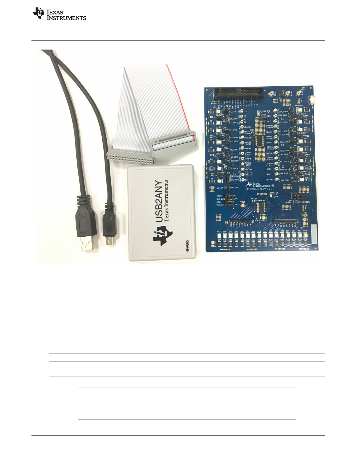
1.3.1 Kit Contents
The TLC6C516EVM kit contains a USB2ANY and TLC6C5816EVM, as showed in Figure 1.
2
TLC6C5816-Q1EVM User's Guide
Copyright © 2017, Texas Instruments Incorporated
SLVUB43–September 2017
Submit Documentation Feedback
Page 3
www.ti.com
Introduction
1.3.2 Additional Items Required
• PC on which to install the TLC6C5816EVM GUI
• DC supply or USB port for LED supply
1.3.3 EVM Parameters
Table 1 shows the typical parameters of TLC6C5816EVM.
V
CC
LED supply 12 V typical
Channel current 20 mA at 12-V LED supply
NOTE: Channel current is set at 20 mA when the LED supply voltage is 12 V. Although the
TLC6C5816-Q1 device can withstand a 40-V maximum LED supply voltage, increased LED
supply voltage increases channel output current. Make sure the channel current is within 50
mA when using higher LED supply voltage.
SLVUB43–September 2017
Submit Documentation Feedback
Figure 1. TLC6C5816EVM Kit
Table 1. TLC6C5816EVM Parameters
Copyright © 2017, Texas Instruments Incorporated
3-5.5 V
TLC6C5816-Q1EVM User's Guide
3
Page 4
LED Supply
IC Supply
Put shunt on J28
to connect
USB2ANY 3.3 V
to IC Supply
USB2ANY
Connector
Put shunt on J32
power U1 in cascading
device mode
Put shunt on J33 and remove
shunt on J31 to configure
EVM for single device mode
Put shunt on J31 and remove
shunt on J31 to configure
EVM for cascading device mode
USB2ANY
TLC6C5816EVM
DC Supply
5V
USB
Cable
V
SENSE
V
CC
GND
Put Shunt on J3 supply
VCC from USB2ANY
Test Setup and Results
2 Test Setup and Results
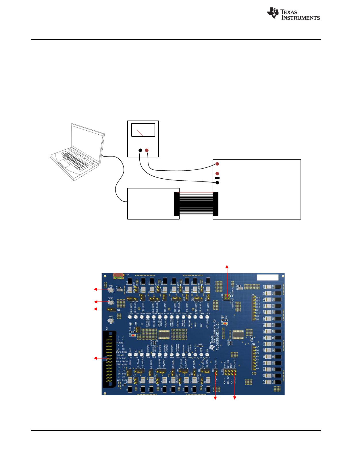
2.1 Hardware Setup
Figure 2 shows the hardware setup of the TLC6C5816EVM.
• Connect a 12-V power supply between TP31 (V
to J27 via a Micro-USB cable.
• Put a shunt on J28 to use the USB2ANY 3.3-V supply to power VCC.
• Connect USB2ANY to the computer.
• Connect the USB2ANY board to the TLC6C5816EVM.
) and TP29 (GND), or connect a 5-V power supply
SENSE
www.ti.com
Figure 2. TLC6C5816EVM Hardware Setup
Figure 3 shows the key connectors to launch the TLC6C5816EVM.
Figure 3. TLC6C5816EVM Key Connectors
4
TLC6C5816-Q1EVM User's Guide
Copyright © 2017, Texas Instruments Incorporated
SLVUB43–September 2017
Submit Documentation Feedback
Page 5
www.ti.com
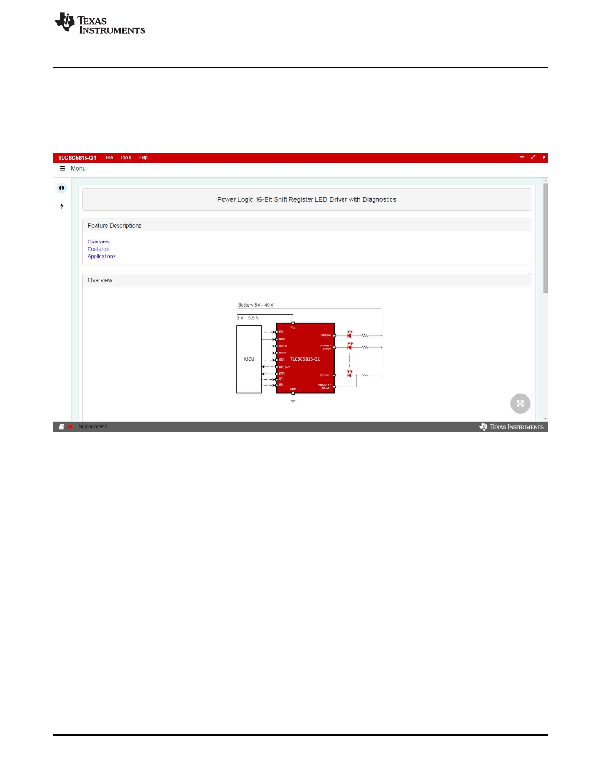
2.2 Software Installation
Download the GUI software from TLC6C5816-Q1 EVM tools folder. After downloading, install the
TLC6C5816EVM GUI on the PC. A shortcut to the GUI is found on the desktop. A shortcut can also be
found in the start-up menu under the Texas Instruments folder. Figure 4 shows the landing page of
TLC6C5816EVM GUI, which contains the TLC6C5816-Q1 introduction information and TLC6C5816EVM
information. Click Menu to show more information.
Test Setup and Results
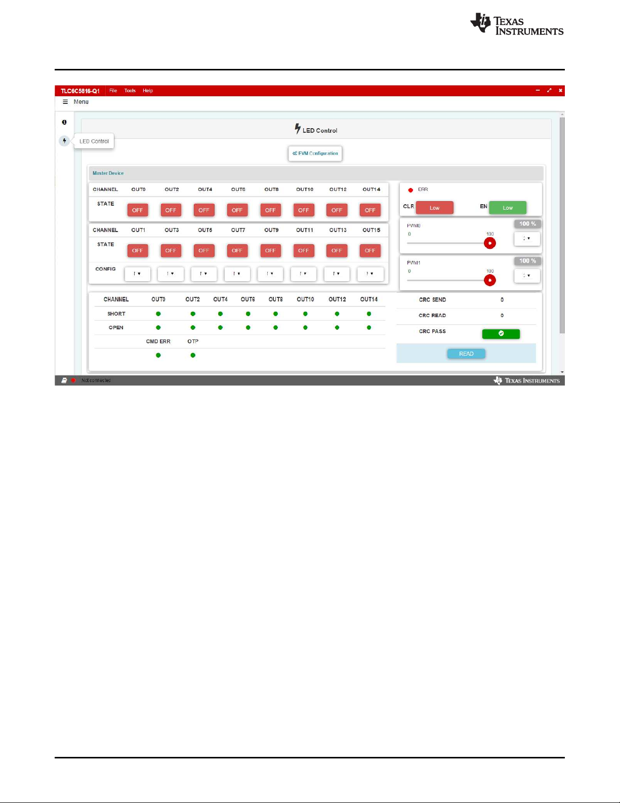
2.3 GUI Function
Click LED Control under Menu, and the GUI displays a detailed LED control panel as shown in Figure 5.
Figure 4. Landing Page of TLCC65916EVM GUI
SLVUB43–September 2017
Submit Documentation Feedback
Copyright © 2017, Texas Instruments Incorporated
TLC6C5816-Q1EVM User's Guide
5
Page 6
Test Setup and Results
www.ti.com
2.3.1 Connection Status
Before using the GUI, make sure connection status indicator in the bottom-left corner is in the green state,
which means the USB2ANY is connected to computer successfully. If the status indicator is in red state,
try to reconnect the USB2ANY cable and restart TLC6C5816EVM GUI.
Figure 5. LED Control Panel
6
TLC6C5816-Q1EVM User's Guide
Copyright © 2017, Texas Instruments Incorporated
SLVUB43–September 2017
Submit Documentation Feedback
Page 7

www.ti.com
Test Setup and Results
Figure 6. TLC6C5816EVM GUI Connection Status
2.3.2 GUI Function
The following section shows detailed information on how to use the GUI to evaluate the TLC6C5816-Q1
device.
2.3.2.1 Channel On and Off Control
Click the ON and OFF button to turn on or turn off the TLC6C5816-Q1 output channels.
Figure 7. Channel Turn On and Off Control
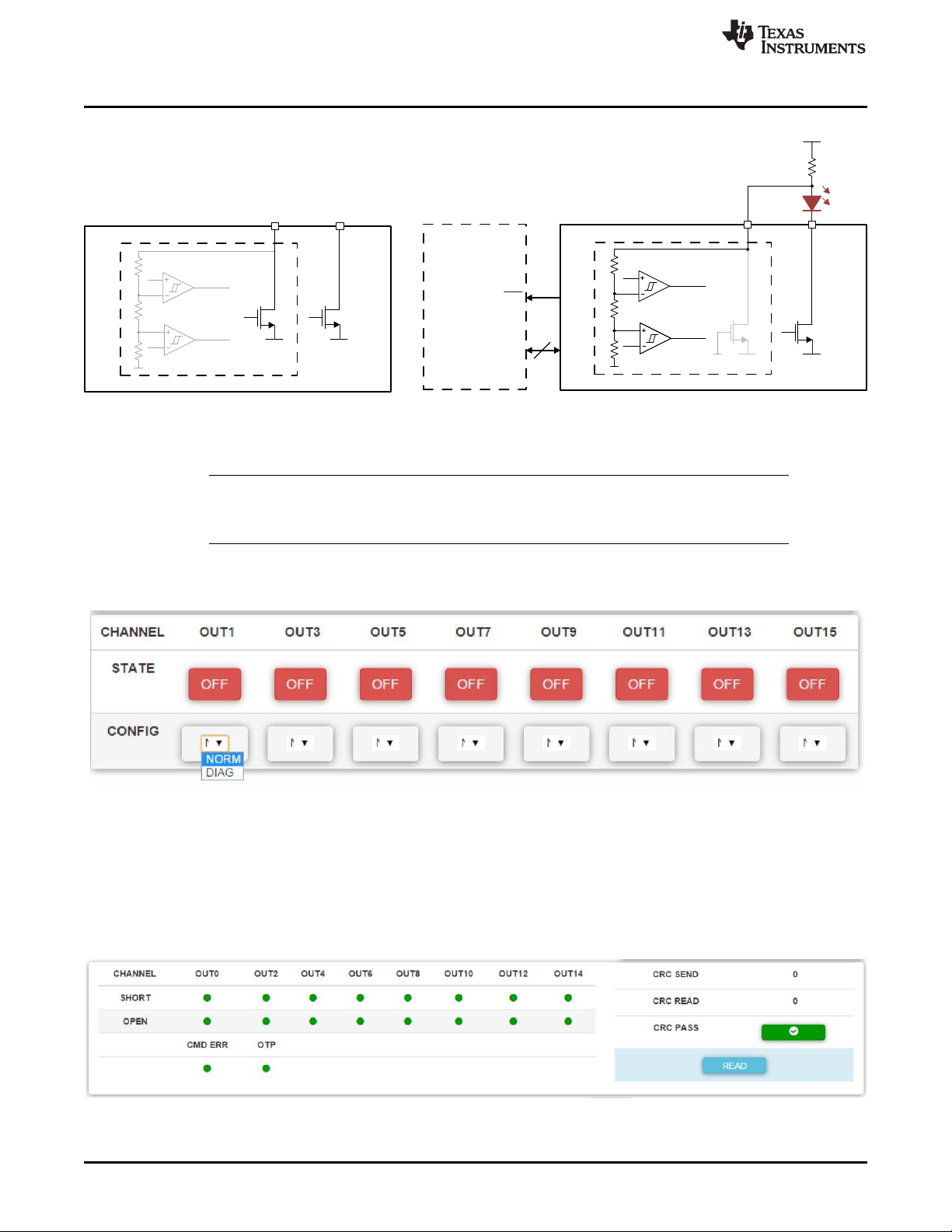
2.3.2.2 Channel Diagnostics Configuration
The even channels of the TLC6C5816-Q1 device have multiple functions. Normally the GUI can be used
for controlling Channel On and Off, but it can also be configured for the LED diagnostics function.
SLVUB43–September 2017
Submit Documentation Feedback
Copyright © 2017, Texas Instruments Incorporated
TLC6C5816-Q1EVM User's Guide
7
Page 8
REF
REF
TLC6C5816
SHORT
OPEN
8 X
Vbat
SPI
REF
REF
ERR
SHORT
OPEN
DRAIN0
8 X8 X
DRAIN1
/DOAG0
DRAIN0
DRAIN1
/DOAG0
8 X8 X
MCU
TLC6C5816
Copyright © 2017, Texas Instruments Incorporated
Test Setup and Results
NOTE: When a channel is configured for LED diagnostics, make sure that the jumpers on the
TLC6C5816EVM are configured properly for the LED diagnostics circuit. Remove the DxOPEN shunt and put on the Dx-DIAG shunt.
www.ti.com
Figure 8. LED Diagnostics Configuration
There is a CONFIG option in the GUI for the TLC6C5816-Q1 even channels. Selecting NORM means the
channel is in normal ON/OFF operation mode. Selecting DIAG enables the diagnostics function.
2.3.2.3 Status Read-Back
When the LED diagnostics function is used, the TLC6C5816EVM GUI provides a status check function.
Pressing READ reads back the TLC6C5816-Q1 status register, including LED open or short status,
command error, overtemperature status, and CRC check status. A green indicator means everything is in
the normal state. A red indicator means there is a fault.
Figure 9. Channel Function Selection
8
TLC6C5816-Q1EVM User's Guide
Figure 10. Status Read-Back
Copyright © 2017, Texas Instruments Incorporated
SLVUB43–September 2017
Submit Documentation Feedback
Page 9

www.ti.com
2.3.2.4 ERR Indicator and Device Reset
The TLC6C5816-Q1 device has an ERROR pin which can indicate when an error happens in the device.
The TLCC65816EVM GUI integrates an ERR indicator which detects the ERROR pin status
simultaneously. Red indicates ERROR pin is pulled down, green means there is no fault on the device.
Both the CLR pin and EN of TLC6C5816-Q1 are low active pins. CLR high means the voltage on CLR pin
is high, so the register clear function is disabled. CLR low means the voltage on the CLR pin is low, so the
register data is cleared.
EN low means the voltage on the EN pin is low and the device is enabled. EN high means the voltage on
the EN pin is high, so the device is disabled. EN high puts the device in low-power mode and clears all the
register data simultaneously.
Figure 11. ERR Indicator and Device Reset
2.3.2.5 PWM Dimming
PWM0 controls the G1 pin to enable the PWM dimming function on CH0–CH7. PWM1 controls the G2 pin
to enable the PWM dimming function on CH8–CH15. The PWM frequency has 5 options: 2 kHz, 1 kHz,
400 Hz, 200 Hz, 100 Hz, and the duty cycle can be configured from 0 to 100%.
Test Setup and Results
2.3.2.6 Cascading Device Mode
The TLC6C5816EVM can be configured as two devices connected in cascade by removing the shunt on
J33 and putting shunts on J31 and J32.
NOTE: The GUI only has channel-on and -off functions for devices in cascade. The GUI does not
implement the LED diagnostics function for devices in cascade. All channels of the cascaded
devices are dimmed by PWM2.
SLVUB43–September 2017
Submit Documentation Feedback
Figure 12. PWM Dimming
Copyright © 2017, Texas Instruments Incorporated
TLC6C5816-Q1EVM User's Guide
9
Page 10

Test Setup and Results
www.ti.com
Figure 13. Cascading Device Configuration
Clicking Slave Device configures the GUI to the cascading device mode.
10
TLC6C5816-Q1EVM User's Guide
Figure 14. GUI for Cascading Device
Copyright © 2017, Texas Instruments Incorporated
SLVUB43–September 2017
Submit Documentation Feedback
Page 11

www.ti.com
3 Board Layout
Board Layout
Figure 15. TLC6C5816EVM Top Layout
SLVUB43–September 2017
Submit Documentation Feedback
Copyright © 2017, Texas Instruments Incorporated
TLC6C5816-Q1EVM User's Guide
11
Page 12

Schematic and Bill of Materials
www.ti.com
Figure 16. TLC6C5816EVM Bottom Layout
4 Schematic and Bill of Materials
The following section contains the EVM schematic and BOM.
12
TLC6C5816-Q1EVM User's Guide
Copyright © 2017, Texas Instruments Incorporated
SLVUB43–September 2017
Submit Documentation Feedback
Page 13

1
2
J1
1
2
J17
1
2
3
J9
1
2
J2
1
2
J18
1
2
3
J10
1
2
J3
1
2
J19
1
2
3
J11
1
2
J4
1
2
J20
1
2
3
J12
1
2
J5
1
2
J21
1
2
3
J13
1
2
J6
1
2
J22
1
2
3
J14
1
2
J7
1
2
J23
1
2
3
J15
1
2
J8
1
2
J24
1
2
3
J16
Yellow12D3
Red12D1
Green12D2
Yellow12D7
Red12D5
Green12D6
White12D12
Yellow12D11
Red12D9
Green12D10
White12D16
Yellow12D15
Red12D13
Green12D14
White12D20
Yellow12D19
Red12D17
Green12D18
White12D24
Yellow12D23
Red12D21
Green12D22
White12D28
Yellow12D27
Red12D25
Green12D26
White
12
D32
Yellow12D31
Red12D29
Green12D30
GND
GND
VCC2
EN2
RCK2
SER_IN2
SRCK2
CLR2
SER_OUT2
ERR2
PWM2
PWM2
VCC1
EN1
RCK1
SER_IN1
SRCK1
CLR1
SER_OUT1
PWM0
PWM1
1.0k
R35
3.3k
R36
ERR2
GND
VCC2
0.1μF
C9
1.0k
R33
3.3k
R34
ERROR
GND
VCC1
0.1μF
C5
VSENSEmax 40V
VCC 3V - 5.5V
GND
VSUPPLY1
VCC1
SER_OUT1
SER_OUT
Remove the shunts for series connect, put
shunt for inden
pendent U1 control.
ERR2
RCK1
SER_IN1
SER_OUT
PWM0
PWM2
PWM1 SRCK1
GND
VCC1 3.3V
VSUPPLY1
GND
SRCK1
SER_OUT1
RCK1
SER_OUT
SRCK2
SER_IN2
RCK2
SER_OUT2
VCC2 VCC1
Headers
Singal Device
Cascade With Two Devices
Put Shunt• to Connect 3.3V
Supply to VCC
Use Micro-USB cable to Power the LED
ERR1
123456789
1011121314
15171921232527
29
16182022242628
30
J26
XG4C-3031
12345
MP1
MP1
MP2
MP2
MP3
MP3
MP4
MP4
MP5
MP5
MP6
MP6
J27
10118192-0001LF
1
2
J33
1234567
8
J31
EN1 EN2
VSUPPLY1
VSUPPLY2
123
4
J32
VSUPPLY1
VSUPPLY2
TP31
TP30
TP29
1
2
J28
Red12D34
Red12D33
Blue
12
D4
Blue12D8
CH0_2
CH1_2
CH2_2
CH3_2
CH4_2
CH5_2
CH6_2
CH7_2
CH8_2
CH9_2
CH10_2
CH11_2
CH12_2
CH13_2
CH14_2
CH15_2
CH0
CH1
CH2
CH3
CH4
CH5
CH6
CH7
CH8
CH9
CH10
CH11
CH12
CH13
CH14
CH15
TP4
TP5
TP6
TP7
TP8
TP9
TP10
TP11
TP12
TP13
TP14
TP28
TP15
TP16
TP17
TP18
TP19
TP20
TP21
TP22
TP23
TP24
TP25
TP26
TP1
TP2
TP3
TP27
VCC1 PWM0 PWM1 CH0 CH1 CH2 CH3 CH4 CH5 CH6 CH7 SER_IN1 CLR1 EN1
GND
5412367
8
J29
5412367
8
J30
CH0_2
CH1_2
CH2_2
CH3_2
CH4_2
CH5_2
CH6_2
CH7_2
CH8_2
CH9_2
CH10_2
CH11_2
CH12_2
CH13_2
CH14_2
CH15_2
RCK1 SRCK1 CH8 C H9 CH10 CH11 CH 12 CH13 CH14 CH15 GND ERR1 GND
SER_OUT1
DRAIN0
4
DRAIN1/DIAG0
5
DRAIN10
20
DRAIN11/DIAG10
21
DRAIN12
22
DRAIN13/DIAG12
23
DRAIN14
24
DRAIN15/DIAG14
25
DRAIN2
6
DRAIN3/DIAG2
7
DRAIN4
8
DRAIN5/DIAG4
9
DRAIN6
10
DRAIN7/DIAG6
11
DRAIN8
18
DRAIN9/DIAG8
19
GND
28
NC
26
RCK
16
SERIN12SEROU T
15
SRCK
17
VCC
1
CLR
13
EN
14
ERR27G12G2
3
PAD
29
U1
TLC6C5816QPWPRQ1
DRAIN0
4
DRAIN1/DIAG0
5
DRAIN10
20
DRAIN11/DIAG10
21
DRAIN12
22
DRAIN13/DIAG12
23
DRAIN14
24
DRAIN15/DIAG14
25
DRAIN2
6
DRAIN3/DIAG2
7
DRAIN4
8
DRAIN5/DIAG4
9
DRAIN6
10
DRAIN7/DIAG6
11
DRAIN8
18
DRAIN9/DIAG8
19
GND
28
NC
26
RCK
16
SER IN12SEROU T
15
SRCK
17
VCC
1
CLR
13
EN
14
ERR27G12G2
3
PAD
29
U2
TLC6C5816QPWPRQ1
220pF
C4
220pF
C8
4.7μF
C2
0.1μF
C3
4.7μF
C6
0.1μF
C7
GND
GND
VSUPPLY2
VSUPPLY1
10.0k
R37
10.0k
R38
VCC1 VCC2
CLR1 CLR2
510
R1
510
R2
510
R3
510
R4
510
R5
510
R6
510
R7
510
R8
510
R9
510
R10
510
R11
510
R12
510
R13
510
R14
510
R15
510
R16
510
R17
510
R18
510
R19
510
R20
510
R21
510
R22
510
R23
510
R24
510
R25
510
R26
510
R27
510
R28
510
R29
510
R30
510
R31
510
R32
CLR2
CLR1
30pF
C18
30pF
C19
30pF
C20
30pF
C21
30pF
C24
30pF
C22
30pF
C23
30pF
C25
30pF
C10
30pF
C11
30pF
C12
30pF
C13
30pF
C16
30pF
C14
30pF
C15
30pF
C17
GND
CH0 CH1 CH2 CH3 CH4 CH5 CH6 CH7 CH8 CH9 CH10 CH13 CH14 CH15
CH12CH11
1000pF
C1
GND
1
2
J25
ERROR ERR1
www.ti.com
Schematic and Bill of Materials
4.1 Schematic
SLVUB43–September 2017
Submit Documentation Feedback
Figure 17. Schematic
Copyright © 2017, Texas Instruments Incorporated
TLC6C5816-Q1EVM User's Guide
13
Page 14

Schematic and Bill of Materials
4.2 BOM
DESIGNATOR DESCRIPTION MANUFACTURER PART NUMBER QUANTITY
C1
C2, C6
C3, C7
C4, C8
C5, C9
C10, C11, C12, C13,
C14, C15, C16, C17,
C18, C19, C20, C21,
C22, C23, C24, C25
D1, D5, D9, D13, D17,
D21, D25, D29
D2, D6, D10, D14,
D18, D22, D26, D30
D3, D7, D11, D15,
D19, D23, D27, D31
D4, D8 LED, blue, SMD OSRAM LB T673-L2P1-25-Z 2
D12, D16, D20, D24,
D28, D32
D33, D34 LED, red, SMD Lite-On LTST-C170KRKT 2
J1, J2, J3, J4, J5, J6,
J7, J8, J17, J18, J19,
J20, J21, J22, J23,
J24, J25, J28, J33
J9, J10, J11, J12, J13,
J14, J15, J16
J26
J27
J29, J30
J31
J32
R1, R2, R3, R4, R5,
R6, R7, R8, R9, R10,
R11, R12, R13, R14,
R15, R16, R17, R18,
R19, R20, R21, R22,
R23, R24, R25, R26,
R27, R28, R29, R30,
R31, R32
R33, R35
R34, R36
R37, R38
Capacitor, ceramic, 1000 pF,
100 V, ±5%, X7R, 0603
Capacitor, ceramic, 4.7 μF, 50
V, ±10%, X6S, 1206
Capacitor, ceramic, 0.1 μF, 50
V, ±10%, X7R, 0603
Capacitor, ceramic, 220 pF,
100 V, ±10%, X7R, 0603
Capacitor, ceramic, 0.1 μF, 16
V, ±5%, X7R, 0603
Capacitor, ceramic, 30 pF, 50
V, ±5%, C0G/NP0, 0603
LED, super red, SMD OSRAM LS T67K-J1L2-1-Z 8
LED, green, SMD OSRAM LG T67K-G2K1-24-Z 8
LED, yellow, SMD OSRAM LY T67K-J2M1-26-Z 8
LED, white, SMD OSRAM
Header, 100 mil, 2×1, gold,
TH
Header, 100mil, 3×1, gold, TH Samtec TSW-103-07-G-S 8
Connector, 15 × 2, 3 A, 300 V
STRT DIP, TH
Receptacle, 0.65 mm, 5×1,
gold, R/A, SMT
Header, 100 mil, 8×1, gold,
TH
Header, 100 mil, 4×2, gold,
TH
Header, 100 mil, 2×2, gold,
TH
Resistor, 510 Ω, 5%, 0.75 W,
AEC-Q200 grade 0, 2010
Resistor, 1.0 kΩ, 5%, 0.1 W,
0603
Resistor, 3.3 kΩ, 5%, 0.1 W,
0603
Resistor, 10.0 kΩ, 1%, 0.1 W,
0603
AVX 06031C102JAT2A 1
TDK
AVX 06035C104KAT2A 2
AVX 06031C221KAT2A 2
AVX 0603YC104JAT2A 2
AVX 06035A300JAT2A 16
Samtec TSW-102-07-G-S 19
Omron XG4C-3031 1
FCI 10118192-0001LF 1
Samtec TSW-108-07-G-S 2
Samtec TSW-104-07-G-D 1
Samtec TSW-102-07-G-D 1
Vishay CRCW2010510RJNEF 32
Vishay CRCW06031K00JNEA 2
Vishay CRCW06033K30JNEA 2
Vishay CRCW060310K0FKEA 2
C3216X6S1H475K160
AB
LW T67C-S2V1-5K8L-
Z
www.ti.com
2
6
14
TLC6C5816-Q1EVM User's Guide
SLVUB43–September 2017
Submit Documentation Feedback
Copyright © 2017, Texas Instruments Incorporated
Page 15

www.ti.com
Schematic and Bill of Materials
DESIGNATOR DESCRIPTION MANUFACTURER PART NUMBER QUANTITY
SH-J1, SH-J2, SH-J3,
SH-J4, SH-J5, SH-J6,
SH-J7, SH-J8, SH-J9,
SH-J10, SH-J11, SHJ12, SH-J13, SH-J14,
SH-J15, SH-J16, SH-
J17, SH-J18, SH-J19
TP1, TP2, TP3, TP4,
TP5, TP6, TP7, TP8,
TP9, TP10, TP11,
TP12, TP13, TP14,
TP15, TP16, TP17,
TP18, TP19, TP20,
TP21, TP22, TP23,
TP24, TP25, TP26,
TP27, TP28
TP29, TP30, TP31 Terminal, turret, TH, double Keystone 1502-2 3
Shunt, 100 mil, gold plated,
black
Test point, miniature, white,
TH
3M 969102-0000-DA 19
Keystone 5002 28
SLVUB43–September 2017
Submit Documentation Feedback
Copyright © 2017, Texas Instruments Incorporated
TLC6C5816-Q1EVM User's Guide
15
Page 16

IMPORTANT NOTICE FOR TI DESIGN INFORMATION AND RESOURCES
Texas Instruments Incorporated (‘TI”) technical, application or other design advice, services or information, including, but not limited to,
reference designs and materials relating to evaluation modules, (collectively, “TI Resources”) are intended to assist designers who are
developing applications that incorporate TI products; by downloading, accessing or using any particular TI Resource in any way, you
(individually or, if you are acting on behalf of a company, your company) agree to use it solely for this purpose and subject to the terms of
this Notice.
TI’s provision of TI Resources does not expand or otherwise alter TI’s applicable published warranties or warranty disclaimers for TI
products, and no additional obligations or liabilities arise from TI providing such TI Resources. TI reserves the right to make corrections,
enhancements, improvements and other changes to its TI Resources.
You understand and agree that you remain responsible for using your independent analysis, evaluation and judgment in designing your
applications and that you have full and exclusive responsibility to assure the safety of your applications and compliance of your applications
(and of all TI products used in or for your applications) with all applicable regulations, laws and other applicable requirements. You
represent that, with respect to your applications, you have all the necessary expertise to create and implement safeguards that (1)
anticipate dangerous consequences of failures, (2) monitor failures and their consequences, and (3) lessen the likelihood of failures that
might cause harm and take appropriate actions. You agree that prior to using or distributing any applications that include TI products, you
will thoroughly test such applications and the functionality of such TI products as used in such applications. TI has not conducted any
testing other than that specifically described in the published documentation for a particular TI Resource.
You are authorized to use, copy and modify any individual TI Resource only in connection with the development of applications that include
the TI product(s) identified in such TI Resource. NO OTHER LICENSE, EXPRESS OR IMPLIED, BY ESTOPPEL OR OTHERWISE TO
ANY OTHER TI INTELLECTUAL PROPERTY RIGHT, AND NO LICENSE TO ANY TECHNOLOGY OR INTELLECTUAL PROPERTY
RIGHT OF TI OR ANY THIRD PARTY IS GRANTED HEREIN, including but not limited to any patent right, copyright, mask work right, or
other intellectual property right relating to any combination, machine, or process in which TI products or services are used. Information
regarding or referencing third-party products or services does not constitute a license to use such products or services, or a warranty or
endorsement thereof. Use of TI Resources may require a license from a third party under the patents or other intellectual property of the
third party, or a license from TI under the patents or other intellectual property of TI.
TI RESOURCES ARE PROVIDED “AS IS” AND WITH ALL FAULTS. TI DISCLAIMS ALL OTHER WARRANTIES OR
REPRESENTATIONS, EXPRESS OR IMPLIED, REGARDING TI RESOURCES OR USE THEREOF, INCLUDING BUT NOT LIMITED TO
ACCURACY OR COMPLETENESS, TITLE, ANY EPIDEMIC FAILURE WARRANTY AND ANY IMPLIED WARRANTIES OF
MERCHANTABILITY, FITNESS FOR A PARTICULAR PURPOSE, AND NON-INFRINGEMENT OF ANY THIRD PARTY INTELLECTUAL
PROPERTY RIGHTS.
TI SHALL NOT BE LIABLE FOR AND SHALL NOT DEFEND OR INDEMNIFY YOU AGAINST ANY CLAIM, INCLUDING BUT NOT
LIMITED TO ANY INFRINGEMENT CLAIM THAT RELATES TO OR IS BASED ON ANY COMBINATION OF PRODUCTS EVEN IF
DESCRIBED IN TI RESOURCES OR OTHERWISE. IN NO EVENT SHALL TI BE LIABLE FOR ANY ACTUAL, DIRECT, SPECIAL,
COLLATERAL, INDIRECT, PUNITIVE, INCIDENTAL, CONSEQUENTIAL OR EXEMPLARY DAMAGES IN CONNECTION WITH OR
ARISING OUT OF TI RESOURCES OR USE THEREOF, AND REGARDLESS OF WHETHER TI HAS BEEN ADVISED OF THE
POSSIBILITY OF SUCH DAMAGES.
You agree to fully indemnify TI and its representatives against any damages, costs, losses, and/or liabilities arising out of your noncompliance with the terms and provisions of this Notice.
This Notice applies to TI Resources. Additional terms apply to the use and purchase of certain types of materials, TI products and services.
These include; without limitation, TI’s standard terms for semiconductor products http://www.ti.com/sc/docs/stdterms.htm), evaluation
modules, and samples (http://www.ti.com/sc/docs/sampterms.htm).
Mailing Address: Texas Instruments, Post Office Box 655303, Dallas, Texas 75265
Copyright © 2017, Texas Instruments Incorporated
Page 17

Mouser Electronics
Authorized Distributor
Click to View Pricing, Inventory, Delivery & Lifecycle Information:
Texas Instruments:
TLC6C5816EVM
 Loading...