

Page 1
User's Guide
TIDU982–June 2015
SimpleLink™ Wi-Fi® CC3200 Smart Plug User's Guide
TIDU982–June 2015 SimpleLink™ Wi-Fi® CC3200 Smart Plug User's Guide
Submit Documentation Feedback
1
Copyright © 2015, Texas Instruments Incorporated
Page 2
www.ti.com
General Texas Instruments High Voltage CC3200 Smart Plug User Safety Guidelines
WARNING
Always follow TI’s setup and application instructions, including
use of all interface components within their recommended
electrical rated voltage and power limits. Always use electrical
safety precautions to help ensure your personal safety and those
working around you. Contact TI’s Product Information Center at
http://support/ti./com for further information.
Save all warnings and instructions for future reference.
Failure to follow warnings and instructions may result in personal injury, property damage, or
death due to electrical shock and burn hazards.
The enclosed CC3200 Smart Plug is intended strictly for customer demonstration purposes under the
direct control of authorized TI field sales personnel with knowledge of electrical safety risks. In order to
minimize risk of personal injury and property damage, at no time shall the CC3200 Smart Plug be
operated or otherwise demonstrated by anyone other than a TI authorized field sales representative. The
CC3200 Smart Plug should NEVER be left with a customer at any time for their own use or any other
evaluation purpose, nor operated in an unintended manner without the direct presence or participation of
the authorized TI field sales representative.
The customer should always be reminded that the final application design circuits are solely the
responsibility of the customer and at no time allow GERBER plots of the CC3200 Smart Plug printed
circuit board layout be provided to customers.
Any other use or application of the CC3200 Smart Plug is strictly prohibited by Texas Instruments.
When demonstrating the CC3200 Smart Plug the following practices and guidelines shall be followed:
1. Work Area Safety:
(a) Keep work area clean and orderly.
(b) Have qualified observers present anytime circuits are energized.
(c) Effective barriers and signage must be present in the area where the CC3200 Smart Plug and its
interface electronics are energized, indicating operation and/or presence of high voltages, for the
purpose of protecting inadvertent access.
(d) All interface circuits including but not limited to power supplies, evaluation modules, instruments,
meters, scopes, and other related apparatus used in a development or demonstration environment
exceeding 50 V
(EPO) protected power strip.
(e) Use stable and non-conductive work surface.
(f) Use adequately insulated clamps and wires to attach measurement probes and instruments. No
freehand testing whenever possible.
/75-V DC must be electrically located within a protected Emergency Power Off
RMS
2
SimpleLink™ Wi-Fi® CC3200 Smart Plug User's Guide TIDU982–June 2015
Copyright © 2015, Texas Instruments Incorporated
Submit Documentation Feedback
Page 3
www.ti.com
2. Electrical Safety:
3. Personal Safety:
Limitation for safe use:
The CC3200 Smart Plug is intended only for demonstration purposes and not to be used at all as part of a
production unit.
As a precautionary measure, it is always a good engineering practice to assume that the entire
CC3200 Smart Plug may have fully accessible and active high voltages.
(a) De-energize the CC3200 Smart Plug and all its interface outputs and electrical loads before
performing any electrical or other diagnostic measurements. Revalidate that the CC3200 Smart
Plug power has been safely de-energized.
(b) With the CC3200 Smart Plug confirmed de-energized, proceed with required electrical circuit
configurations or other CC3200 Smart Plug interface hook-ups, while still assuming the load circuit
connected to the CC3200 Smart Plug and accompanying measuring instruments are electrically
live.
(c) Once the CC3200 Smart Plug readiness is complete, proceed with energization as intended.
WARNING
While the CC3200 Smart Plug is energized, never touch any of its
electrical circuits or controlled interface loads as they could be at
high voltages capable of causing electrical shock hazard.
(a) Wear personal protective equipment such as latex gloves or safety glasses with side shields, or
protect the EVM in an adequate lucent plastic box with interlocks from accidental touch.
TIDU982–June 2015 SimpleLink™ Wi-Fi® CC3200 Smart Plug User's Guide
Submit Documentation Feedback
3
Copyright © 2015, Texas Instruments Incorporated
Page 4

www.ti.com
Contents
1 Introduction ................................................................................................................... 5
2 Requirements ................................................................................................................ 5
3 Demo Overview.............................................................................................................. 6
4 Smart Plug.................................................................................................................... 7
5 Key Components............................................................................................................. 8
6 Install Android App......................................................................................................... 10
7 Network Connection ....................................................................................................... 10
8 Starting the Demo — Android Application .............................................................................. 11
9 Starting the Demo — Exosite Website .................................................................................. 18
10 Software Files............................................................................................................... 20
List of Figures
1 Main Interface ................................................................................................................ 6
2 Main Components of Smart Plug.......................................................................................... 7
3 Provisioning by Using Wi-Fi Starter App.................................................................................. 9
4 Sign-In Screen.............................................................................................................. 11
5 Menu......................................................................................................................... 11
6 mDNS With Device Found ................................................................................................ 12
7 Adding Current Device to Exosite Account ............................................................................. 12
8 Device is Already Listed................................................................................................... 12
9 Adding a Device Manually by Entering Information.................................................................... 13
10 Main List With Smart Plug Running in Local Connection............................................................. 13
11 Device Screen With Cloud Connection Running....................................................................... 14
12 Plotting With Apparent Power Selected................................................................................. 14
13 Scheduling Table........................................................................................................... 15
14 Editing Detail................................................................................................................ 15
15 Displaying Device Details ................................................................................................. 15
16 Calibration Screen (Local Connection Only)............................................................................ 16
17 Enable/Disable Cloud Secure Connection (Local Connection Only) ................................................ 16
18 Certificate Update Screen................................................................................................. 16
19 Signed-Out Screen......................................................................................................... 17
20 Application Exit ............................................................................................................. 17
21 Exosite Start Page ......................................................................................................... 18
22 Metrology Data Monitoring Options...................................................................................... 19
23 Device Menu in Android................................................................................................... 20
24 Delete Device from Exosite Website .................................................................................... 20
1 Status LED Behavior Chart................................................................................................. 8
2 Smart Plug Provisioning .................................................................................................... 9
3 mDNS Options.............................................................................................................. 12
4 Adding New Device Setup ................................................................................................ 13
4
SimpleLink™ Wi-Fi® CC3200 Smart Plug User's Guide TIDU982–June 2015
List of Tables
Copyright © 2015, Texas Instruments Incorporated
Submit Documentation Feedback
Page 5

www.ti.com
1 Introduction
There is an increasing application requirement for Wi-Fi-enabled energy measurement and control. This
increase is manifested in end products like smart plugs, smart receptacles, and in general application
spaces such as home appliance, smart grid, and building automation. The goal was to offer a form-factor
reference design and application software that could very quickly be turned into a production Smart Plug.
The deliverables would also address application requirements in connected energy measurement and any
cloud-connected device. Updated information will be posted on the C3200 Smart Plug product page.
2 Requirements
Hardware:
• CC3200 Smart Plug
• Android™ device with Android 4.1 (Jelly Bean, API level 16) or above
• Access point with internet connection
Software:
• Smart Plug Android application in the package
• Exosite account
Introduction
TIDU982–June 2015 SimpleLink™ Wi-Fi® CC3200 Smart Plug User's Guide
Submit Documentation Feedback
5
Copyright © 2015, Texas Instruments Incorporated
Page 6
Demo Overview
3 Demo Overview
3.1 Android Application
The Smart Plug Android application is a user-friendly tool to interface with the CC3200 Smart Plug. All
features mentioned in the introduction can be accessed in this application. The source code of this
application is also available for download in the product’s wiki page:
http://processors.wiki.ti.com/index.php/CC31xx_%26_CC32xx_Provisioning.
www.ti.com
3.2 Exosite® Website
Exosite is the cloud service to be used with the CC3200 Smart Plug. The service provides not only the
storage for metrology data or an alternative platform to monitor the Smart Plug, but also a communication
bridge between the Smart Plug and the Android application. When a mobile device is not in the same local
network as the Smart Plug, the user can still access all the readings and most controlling features
because the cloud service is doing all the work, making it almost seamless.
Figure 1. Main Interface
6
SimpleLink™ Wi-Fi® CC3200 Smart Plug User's Guide TIDU982–June 2015
Copyright © 2015, Texas Instruments Incorporated
Submit Documentation Feedback
Page 7
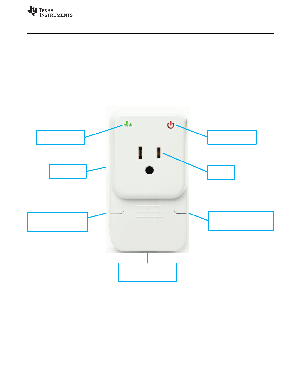
Status Indicator
(Back) Plug
(Right Side Wall)
Relay Control Button
(Bottom Side Wall)
Reset Button
Power Indicator
Socket
(Left Side Wall)
Provisioning Button
www.ti.com
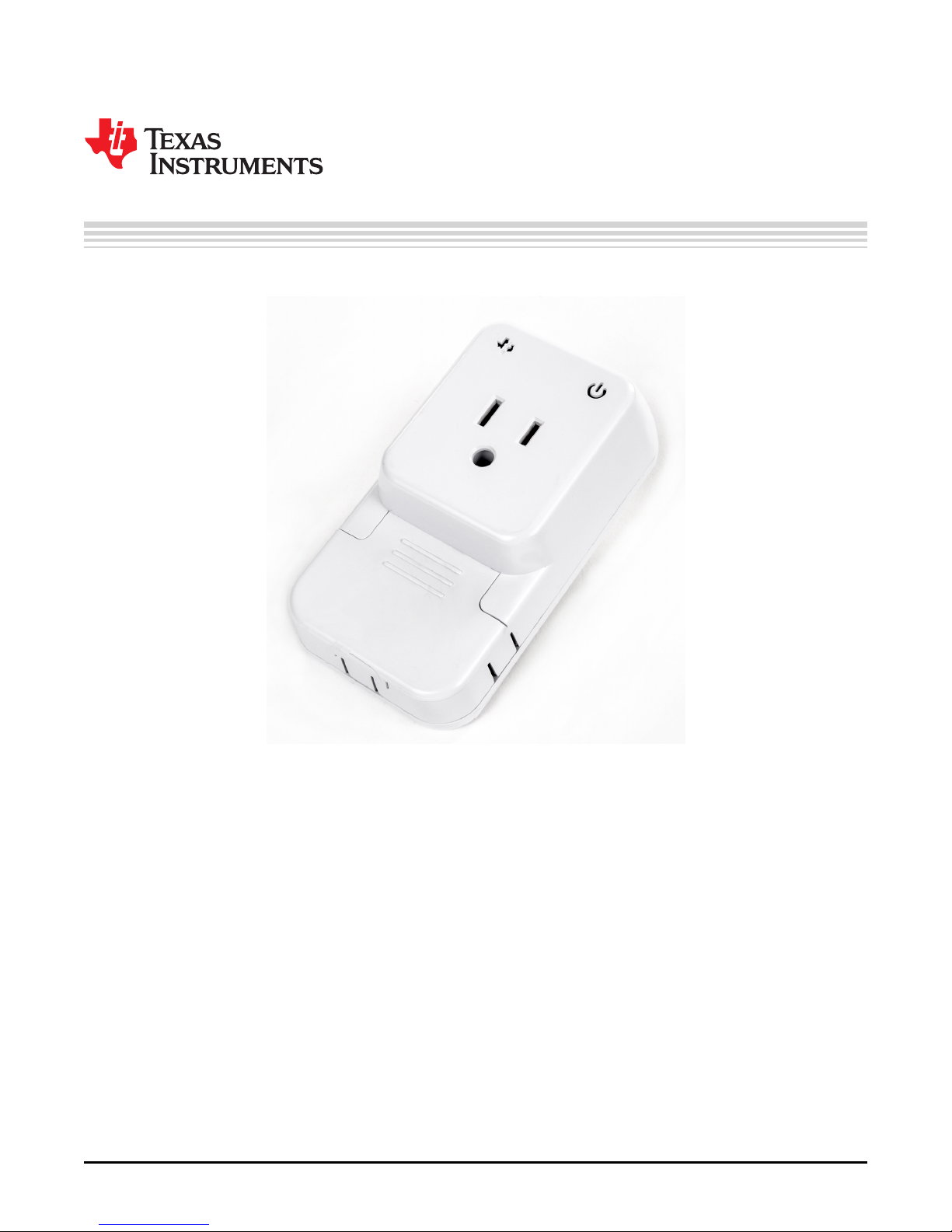
4 Smart Plug
The Smart Plug has a very simple look which simplifies the user experience. The main components are:
• Plug: On the back side of the Smart Plug, for plugging into a wall outlet.
• Socket: For plugging a device in the appliance.
• Power Indicator: LED indicator telling whether the Smart Plug is powered or not.
• Status Indicator: LED indicator telling the status of the Smart Plug.
• Provisioning Control Button: Performs provisioning.
• Relay Control Button: Manually controls the relay status of the Smart Plug.
• Reset Button: Resets the device forcefully.
Smart Plug
Figure 2. Main Components of Smart Plug
TIDU982–June 2015 SimpleLink™ Wi-Fi® CC3200 Smart Plug User's Guide
Submit Documentation Feedback
7
Copyright © 2015, Texas Instruments Incorporated
Page 8

Key Components
5 Key Components
5.1 Plug
The plug is located on the back side of the Smart Plug. Plug it into a wall outlet to receive power. The
device is capable of loading 100 to 240 V and 50- or 60-Hz power supply. If needed, use an adapter to fit
your local socket type.
5.2 Socket
Plug the appliance into the socket to read power values. Use an adapter to fit if needed.
5.3 Power Indicator
Power light is represented by a red LED on the top right-hand corner. Being on means the Smart Plug is
powered, off otherwise.
5.4 Status Indicator
The status indicator is represented by the three-color green-blue-red LED with a TI logo. This light tells the
user the status of the Smart Plug to make sure the device is functioning the way the user intends. Table 1
lists all possible statuses.
LEFT LED BEHAVIOR STATUS
Red
Blue
Magenta
Green
Flashing slowly, then steady The device is powering up, then fully powered
Table 1. Status LED Behavior Chart
Flashing quickly Any error indication
Flashing quickly The device is in Smart Config mode
Flashing slowly Trying to connect to a Wi-Fi network
Connected to Wi-Fi with IP address
Steady
Steady Connected to the mobile app
Flashing NOTE: If the Smart Plug is transferring data to both the cloud and the android
Steady Internet connection available or connected to the cloud
Flashing During data transfer
NOTE: If the device is unable to connect to the AP, LED blinks slowly during this
period and the Smart Config button can be pressed
During data transfer
app, the cloud’s representation dominates.
www.ti.com
8
SimpleLink™ Wi-Fi® CC3200 Smart Plug User's Guide TIDU982–June 2015
Copyright © 2015, Texas Instruments Incorporated
Submit Documentation Feedback
Page 9

www.ti.com
5.5 Provisioning Button
On a new Smart Plug, since there is no Wi-Fi profile stored on the device, provisioning becomes important
in order for the Smart Plug to connect to the AP of your desire.
The Smart Plug supports three types of provisioning:
PROVISIONING METHOD PROVISIONING BUTTON ACTION HOW TO USE
Smart Config Hold for 1 to 3 seconds Wi-Fi Starter App
AP Hold for 3 to 10 seconds Webpage
WPS Hold for >10 seconds WPS compatible router
Key Components
Table 2. Smart Plug Provisioning
Figure 3. Provisioning by Using Wi-Fi Starter App
For more information about provisioning, visit the CC31xx and CC32xx Provisioning wiki page:
http://processors.wiki.ti.com/index.php/CC31xx_%26_CC32xx_Provisioning.
Once the Smart Plug is connected to the AP, the green LED will light up, indicating a successful
connection.
5.6 Relay Control Button
Press this button to control the relay status forcefully. This button overrides any scheduled relay from the
software. Users will have to re-enter the scheduling if desiring this feature.
5.7 Reset Button
Press this button to reset the device. Please be aware that all existing connections will be terminated.
Stored Wi-Fi profiles are not affected.
TIDU982–June 2015 SimpleLink™ Wi-Fi® CC3200 Smart Plug User's Guide
Submit Documentation Feedback
9
Copyright © 2015, Texas Instruments Incorporated
Page 10

Exosite Cloud
with Web Interface
Exosite
Cloud
Install Android App
6 Install Android App
The companion Android app SmartPlug.apk is included in the package. However, since this app is not
released on Google Play, users will need to use an alternative way to install the .apk file onto their
devices. Please visit this website for instruction on how to install the .apk file: http://www.cnet.com/how-
to/how-to-install-apps-outside-of-google-play/
7 Network Connection
To read the Smart Plug data, a user may choose to use the Android app or the Exosite website for this
task. However, the Android app is capable of monitoring under a local network connection and cloud
connection. One convenient feature for this dual connection mode is that the user does not necessarily
need an internet connection or a cloud account to bring up the demo. If a local network is the only
environment to work with, use the Android app to be the sole monitoring device.
7.1 Local Connection with Android App
When both the Smart Plug and the Android app are located in the same local network, the app can
directly monitor the values without any external internet connection.
www.ti.com
7.2 Cloud Connection With Android App
There are scenarios when the Smart Plug and the Android app are not located in the same local network.
In such case, cloud connection becomes very useful because users can monitor the data at anywhere, as
long as an internet connection exists. The Android app has Exosite API integrated into it so all data
reported to the cloud server can be seen directly on the app.
7.3 Cloud Connection with Exosite Website
Whether or not the user uses the Android app to monitor Smart Plug data, all values are recorded on the
Exosite server for users to login through a web browser and see the values.
10
SimpleLink™ Wi-Fi® CC3200 Smart Plug User's Guide TIDU982–June 2015
Copyright © 2015, Texas Instruments Incorporated
Submit Documentation Feedback
Page 11

www.ti.com
8 Starting the Demo — Android Application
8.1 Signing in With an Exosite Account
Upon entering the app the first time, the user may sign up or use an existing account. To sign up for a free
account, simply provide an email address and a password. For new and existing accounts, passwords
must meet these requirements:
• At least six (6) characters
• Contains at least one number
• Contains at least one letter
• Contains at least one non number or capital letter
• Cannot begin or end with spaces
• Must be different from current password
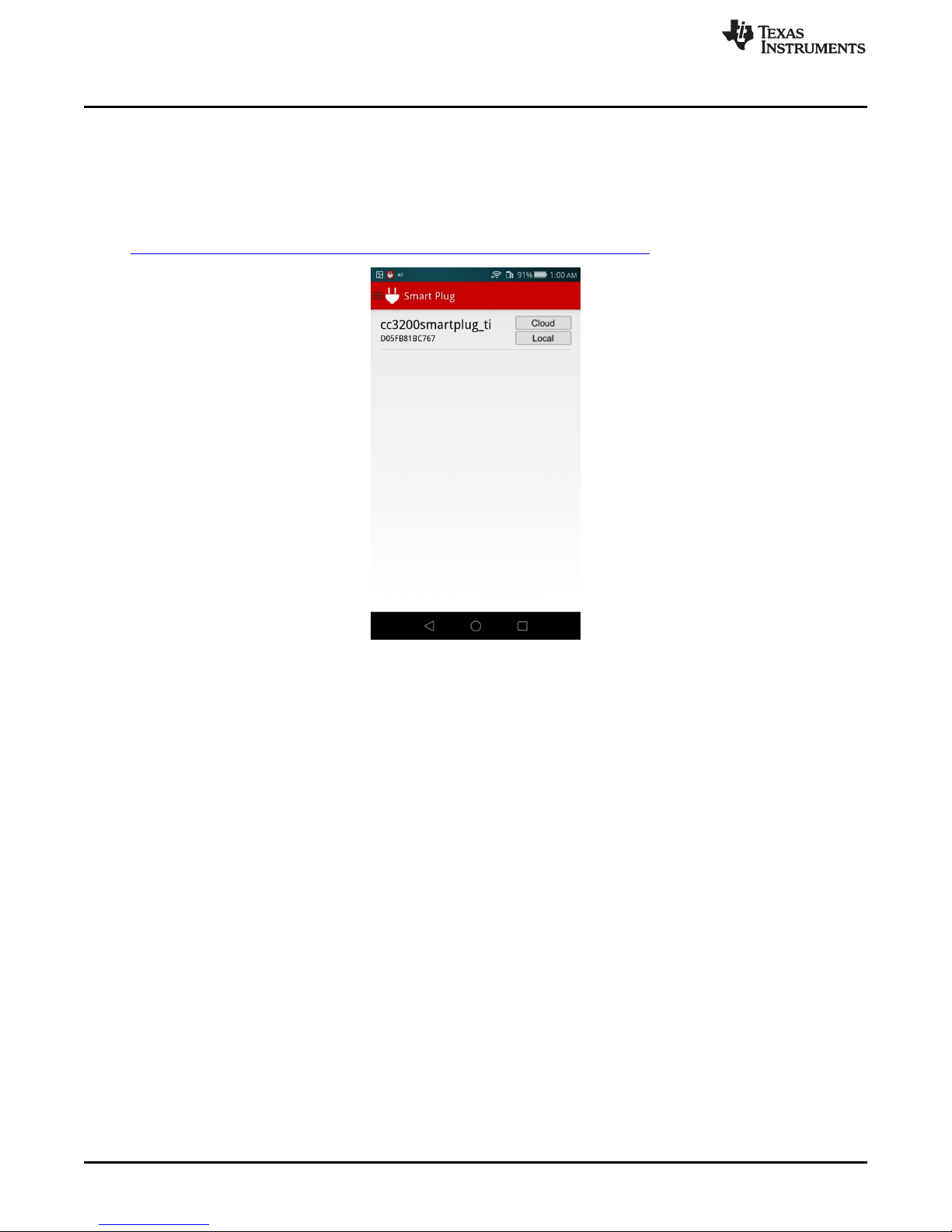
Once signed in, the app will take the user to the main page with a list of devices that is either stored on
the cloud or locally. The list may be empty if there are not any known devices added. The user may also
choose to skip the sign-in process and proceed directly to the list; however, this will prevent the user from
communicating with the device through the Exosite cloud service. Metrology data monitor and other
controls are only accessible through local connection.
The main menu can be brought onto the screen by swiping from the left edge of the screen or by touching
the application icon at the top of the screen. The menu provides access to all essential functionalities to
navigate inside the app easier (Figure 5).
There are three ways to add a new device:
• Add a Device: Add a device manually by entering relevant information (see Figure 8).
• mDNS Search: Search for local devices using mDNS (see Figure 6).
• Sync Devices: If the user has added devices to an Exosite account before, this option will retrieve all of
them and list them here.
Starting the Demo — Android Application
Figure 4. Sign-In Screen Figure 5. Menu
TIDU982–June 2015 SimpleLink™ Wi-Fi® CC3200 Smart Plug User's Guide
Submit Documentation Feedback
11
Copyright © 2015, Texas Instruments Incorporated
Page 12

Starting the Demo — Android Application
8.2 Adding a New Device Through mDNS
When the CC3200 Smart Plug and mobile device are in the same local network, mDNS searching is the
easiest way to add a new device. mDNS resolves host names to IP addresses within small networks that
do not include a local DNS server. It allows the Android device to discover the Smart Plug and ultimately
connects to it without manually entering IP addresses.
When a Smart Plug is found within the same network, one of these options will show up:
Table 3. mDNS Options
OPTION DESCRIPTION
The device is not in the main list. Click this button to add the device to the list. A confirmation
screen will show up, asking the user whether to add this device to the cloud account or not
(see Figure 7). This screen will not be shown if the user is not signed into a cloud account.
This image is not clickable. It indicates that the device is already listed in the app (see Figure 8).
Check the main screen to see the device.
This button will show if the device is already in the main list, but has an unmatched IP address.
Click on this to update the IP address.
www.ti.com
Figure 6. mDNS With Device Found Figure 7. Adding Current Device to Figure 8. Device is Already Listed
12
SimpleLink™ Wi-Fi® CC3200 Smart Plug User's Guide TIDU982–June 2015
Exosite Account
Copyright © 2015, Texas Instruments Incorporated
Submit Documentation Feedback
Page 13

www.ti.com
8.3 Adding a New Device Manually
Another way to add a device is by entering all the information manually. This method is particularly useful
if the user is adding a Smart Plug that will be used in the future but does not have it running at the
moment. Table 4 describes all fields in the page.
FIELD REQUIRED DESCRIPTION
Name Yes Name of the device
Serial Number MAC address of the device. This is also known as the serial number for the
(MAC Address) Exosite cloud.
Local Connection Address — IP address of the device for local connection
Auto
Cloud Connection Only —
Local Connection Only
Yes
Starting the Demo — Android Application
Table 4. Adding New Device Setup
Connection policy for the device:
• Auto: Using cloud as the default, but will switch to local connection if the
cloud connection is lost
• Cloud Connection Only: Forced cloud connection
• Local Connection Only: Forced local connection
Portal —
Vendor —
Model — purpose. This is also required if the user adds the current Smart Plug into the
Local Add Only — the cloud account will not be able to communicate with it. If the user is not signed
The portal in the account to which the Smart Plug will be added. No modification is
needed if the user has only one portal.
The name of the vendor. This field is not modifiable due to demonstration purpose.
This is required if the user adds the current Smart Plug into the cloud account.
The name of the model. This field is not modifiable due to its demonstration
cloud account.
Enable this check box to add this Smart Plug to the mobile device only. It means
in, this field makes no difference.
Figure 9. Adding a Device Manually by Figure 10. Main List With Smart Plug Running in
Entering Information Local Connection
TIDU982–June 2015 SimpleLink™ Wi-Fi® CC3200 Smart Plug User's Guide
Submit Documentation Feedback
13
Copyright © 2015, Texas Instruments Incorporated
Page 14

Starting the Demo — Android Application
8.4 Metrology Data Monitoring
One of the main features of the Smart Plug reference design is the monitoring of metrology data. It
currently displays the following metrology data:
• Active Power
• Average Power
• Reactive Power
• Apparent Power
• Voltage
• Current
• Frequency
• Power Factor
• Total Energy Consumption
Besides monitoring, it also has the ability to send data to the Smart Plug to improve user experience.
Functionality includes the following:
• Device Powering Status
• Scheduling
• Power & Energy Threshold
• Power Saving Status
• 24-Hour Energy Summary
• Calibration
• Enable/Disable Secure Cloud Connection (SSL/TLS)
• Cloud Connection Certificate Update
Refer to the CC3200 Smart Plug design guide for implementation details (TIDU983).
www.ti.com
Figure 11. Device Screen With Cloud Figure 12. Plotting With Apparent Power Selected
Connection Running
14
SimpleLink™ Wi-Fi® CC3200 Smart Plug User's Guide TIDU982–June 2015
Copyright © 2015, Texas Instruments Incorporated
Submit Documentation Feedback
Page 15

www.ti.com
• Device Powering Status
• Scheduling
• Editing Details
• Device Details
• Threshold Status
• Power Saving Status
Starting the Demo — Android Application
This is also known as "relay". This option controls whether or not to supply power to the device
plugged into the Smart Plug. Toggling this field will override the Scheduling setting.
Also called "switch table" in the code, this option schedules the relay on weekly bases. The days are
divided into three categories: weekdays, Saturday, and Sunday. Each category has four time fields to
modify. Users can specify the wake-up time (to turn on), leaving time (to turn off), returning time (to
turn on), and sleeping time (to turn off), simulating a daily routine of a typical person (see Figure 13).
This item is located in the drawer menu on the left side of the screen. The user can make changes to
fields as shown in Figure 14. There are currently three connection options: Auto, Cloud Connection
Only, and Local Connection Only.
A dialog box will pop up when the user clicks on the Device Details button (see Figure 15). This dialog
shows all essential information to the user about the Smart Plug, mainly for debugging purposes.
This sets the threshold values for power and energy. Once a value exceeds the specified threshold
value, the corresponding metrology value will start blinking red, and the user will receive email alerts if
the Smart Plug is connected to the user’s cloud account.
The user has the option to enable or disable power saving. Once enabled, the metrology reporting
period can be changed to report data every 5 to 60 seconds.
Figure 13. Scheduling Table Figure 14. Editing Detail Figure 15. Displaying Device Details
TIDU982–June 2015 SimpleLink™ Wi-Fi® CC3200 Smart Plug User's Guide
Submit Documentation Feedback
15
Copyright © 2015, Texas Instruments Incorporated
Page 16

Starting the Demo — Android Application
8.5 Local versus Cloud Connection
The followings options can only be changed under a local connection:
• 24-Hour Energy Summary
The 24-Hour Average button displays the hourly average energy summary in the past 24 hours.
• Calibration
This option calibrates voltage and current readings if the displayed values are not shown correctly.
This also displays scale factors and noises information (see Figure 16).
• Enable/Disable Secure Cloud Connection (SSL/TLS)
This is a demonstration to show the ability to communicate with the cloud service with a non-secure
connection or with an SSL/TLS connection.
• Certificate Update
Certificates come with expiration dates. Once expired, SSL/TLS communication will no longer be
working. Having the ability to update the certificate is crucial to make the Smart Plug able to work in
the future if the user has not used it for a long time. Click on the button to browse the certificate file to
update.
As of right now, only the X509 file extension format is supported (.der extension).
www.ti.com
Figure 16. Calibration Screen Figure 17. Enable/Disable Cloud Figure 18. Certificate Update Screen
(Local Connection Only) Secure Connection
16
SimpleLink™ Wi-Fi® CC3200 Smart Plug User's Guide TIDU982–June 2015
(Local Connection Only)
Copyright © 2015, Texas Instruments Incorporated
Submit Documentation Feedback
Page 17

www.ti.com
8.6 Application Termination
Upon pressing the back or home button on the bottom of the screen, the app interface will exit, but the
application is still running as a service in the background. Any established communication will sustain and
receive metrology updates constantly. To exit the application, select "Exit Application" from the menu
(see Figure 20).
8.7 Troubleshooting and Bug Report
Due to the Android application being used for demonstration purposes and not for end-user distribution, it
may contain some bugs. This section briefly describes several problematic scenarios and possible
resolutions:
• Cloud Synchronization
– If the user cannot add a device to the cloud account, contact the local FAE. This device may have
been registered by other users before and have not been removed from their account.
– If a device cannot be deleted (it may show a short message saying "Error"). Manually delete all
data by going to Settings → Apps → All → Smart Plug → Clear Data. This path may vary among
different Android devices.
• Application Crash
– When encountering application crash, a dialog will show up and asks the user to report the bug to
the developer. Send the report to the local FAE so TI can improve the robustness of the application.
– When encountering an application crash, the application may restart automatically. However,
application stability is not guaranteed at this point. Exit the application through the "Exit Application"
option in the menu and restart.
Starting the Demo — Android Application
Figure 19. Signed-Out Screen Figure 20. Application Exit
TIDU982–June 2015 SimpleLink™ Wi-Fi® CC3200 Smart Plug User's Guide
Submit Documentation Feedback
17
Copyright © 2015, Texas Instruments Incorporated
Page 18

Starting the Demo — Exosite Website
9 Starting the Demo — Exosite Website
An alternative way to monitor the Smart Plug is by using the cloud website. Exosite is the default cloud
service provider for Smart Plug. Exosite cloud allows the user to monitor and manipulate the Smart Plug
even if user’s Android device is not within the same local network of the Smart Plug. Register a free
account by using the Android application or through the following link to the TI-Exosite Site:
https://ti.exosite.com/login.
Once signed in, two columns of information panels and a menu appear on the left side of the screen (see
Figure 21). If the user has any existing device that was added before through the Android application or
on the website, the user can see them all in the "Device List" panel on the right. Note that devices listed
here may not be all Smart Plugs. This page is essentially a portal to all TI devices, and Smart Plug is one
of them. However, the Android application will only display Smart Plug (specifically, Smart Plug V2)
devices.
www.ti.com
9.1 Adding a New Device
To add a new device, click the link in the Step 2 shown on the left panel in Figure 21.
1. Check "Select a supported device" and choose "Smart Plug V2".
2. Click Continue.
3. Enter MAC address and name of the device. The location field is optional.
4. Click Continue.
Once the device is successfully added, the user will be given a CIK number as a reference. This number
is generated based on the MAC address. If an error appears saying that the device cannot be added,
check with the local FAE to make sure the device is not registered to another account.
Going back to the home screen, the new device is in the list on the right. Click on the device name to start
monitoring.
Figure 21. Exosite Start Page
18
SimpleLink™ Wi-Fi® CC3200 Smart Plug User's Guide TIDU982–June 2015
Copyright © 2015, Texas Instruments Incorporated
Submit Documentation Feedback
Page 19

www.ti.com
9.2 Metrology Data Monitoring
The Exosite cloud webpage provides basic monitoring that closely resembles the Android application. The
website is mainly used an alternative monitoring interface in case an Android device is not available.
Starting the Demo — Exosite Website
Figure 22. Metrology Data Monitoring Options
TIDU982–June 2015 SimpleLink™ Wi-Fi® CC3200 Smart Plug User's Guide
Submit Documentation Feedback
19
Copyright © 2015, Texas Instruments Incorporated
Page 20

Starting the Demo — Exosite Website
9.3 Removing Device from Exosite
If the same Smart Plug needs to be used by someone else in the future, delete the MAC address stored
on the cloud to allow the next user to register the same device in his or her account. Only one MAC
address can be registered by one user at the same time.
There are two ways to delete the device from the cloud:
1. If the Smart Plug was added to your cloud
account via the Android application, you can
simply delete the device from the App menu
by choosing the "Delete Device" option (see
Figure 23). Synchronization will be done
automatically.
2. To delete the device from the cloud website,
go to the menu on the left side of the page
and click "Devices" → your Smart Plug
device. Under the "Delete Device" section,
type "confirm" in the box and click "DELETE"
(see Figure 24).
www.ti.com
10 Software Files
To download the software files for this reference design, refer to http://www.ti.com/tool/TIDC-
CC3200smartplug.
Figure 23. Device Menu in Android
Figure 24. Delete Device from Exosite Website
20
SimpleLink™ Wi-Fi® CC3200 Smart Plug User's Guide TIDU982–June 2015
Copyright © 2015, Texas Instruments Incorporated
Submit Documentation Feedback
Page 21

IMPORTANT NOTICE
Texas Instruments Incorporated and its subsidiaries (TI) reserve the right to make corrections, enhancements, improvements and other
changes to its semiconductor products and services per JESD46, latest issue, and to discontinue any product or service per JESD48, latest
issue. Buyers should obtain the latest relevant information before placing orders and should verify that such information is current and
complete. All semiconductor products (also referred to herein as “components”) are sold subject to TI’s terms and conditions of sale
supplied at the time of order acknowledgment.
TI warrants performance of its components to the specifications applicable at the time of sale, in accordance with the warranty in TI’s terms
and conditions of sale of semiconductor products. Testing and other quality control techniques are used to the extent TI deems necessary
to support this warranty. Except where mandated by applicable law, testing of all parameters of each component is not necessarily
performed.
TI assumes no liability for applications assistance or the design of Buyers’ products. Buyers are responsible for their products and
applications using TI components. To minimize the risks associated with Buyers’ products and applications, Buyers should provide
adequate design and operating safeguards.
TI does not warrant or represent that any license, either express or implied, is granted under any patent right, copyright, mask work right, or
other intellectual property right relating to any combination, machine, or process in which TI components or services are used. Information
published by TI regarding third-party products or services does not constitute a license to use such products or services or a warranty or
endorsement thereof. Use of such information may require a license from a third party under the patents or other intellectual property of the
third party, or a license from TI under the patents or other intellectual property of TI.
Reproduction of significant portions of TI information in TI data books or data sheets is permissible only if reproduction is without alteration
and is accompanied by all associated warranties, conditions, limitations, and notices. TI is not responsible or liable for such altered
documentation. Information of third parties may be subject to additional restrictions.
Resale of TI components or services with statements different from or beyond the parameters stated by TI for that component or service
voids all express and any implied warranties for the associated TI component or service and is an unfair and deceptive business practice.
TI is not responsible or liable for any such statements.
Buyer acknowledges and agrees that it is solely responsible for compliance with all legal, regulatory and safety-related requirements
concerning its products, and any use of TI components in its applications, notwithstanding any applications-related information or support
that may be provided by TI. Buyer represents and agrees that it has all the necessary expertise to create and implement safeguards which
anticipate dangerous consequences of failures, monitor failures and their consequences, lessen the likelihood of failures that might cause
harm and take appropriate remedial actions. Buyer will fully indemnify TI and its representatives against any damages arising out of the use
of any TI components in safety-critical applications.
In some cases, TI components may be promoted specifically to facilitate safety-related applications. With such components, TI’s goal is to
help enable customers to design and create their own end-product solutions that meet applicable functional safety standards and
requirements. Nonetheless, such components are subject to these terms.
No TI components are authorized for use in FDA Class III (or similar life-critical medical equipment) unless authorized officers of the parties
have executed a special agreement specifically governing such use.
Only those TI components which TI has specifically designated as military grade or “enhanced plastic” are designed and intended for use in
military/aerospace applications or environments. Buyer acknowledges and agrees that any military or aerospace use of TI components
which have not been so designated is solely at the Buyer's risk, and that Buyer is solely responsible for compliance with all legal and
regulatory requirements in connection with such use.
TI has specifically designated certain components as meeting ISO/TS16949 requirements, mainly for automotive use. In any case of use of
non-designated products, TI will not be responsible for any failure to meet ISO/TS16949.
Products Applications
Audio www.ti.com/audio Automotive and Transportation www.ti.com/automotive
Amplifiers amplifier.ti.com Communications and Telecom www.ti.com/communications
Data Converters dataconverter.ti.com Computers and Peripherals www.ti.com/computers
DLP® Products www.dlp.com Consumer Electronics www.ti.com/consumer-apps
DSP dsp.ti.com Energy and Lighting www.ti.com/energy
Clocks and Timers www.ti.com/clocks Industrial www.ti.com/industrial
Interface interface.ti.com Medical www.ti.com/medical
Logic logic.ti.com Security www.ti.com/security
Power Mgmt power.ti.com Space, Avionics and Defense www.ti.com/space-avionics-defense
Microcontrollers microcontroller.ti.com Video and Imaging www.ti.com/video
RFID www.ti-rfid.com
OMAP Applications Processors www.ti.com/omap TI E2E Community e2e.ti.com
Wireless Connectivity www.ti.com/wirelessconnectivity
Mailing Address: Texas Instruments, Post Office Box 655303, Dallas, Texas 75265
Copyright © 2015, Texas Instruments Incorporated
 Loading...