

Page 1

User’s Guide
SNLU108 – July 2012
SERDESUB-16OVT EVM User’s Guide
SNLU108 – July 2012 SERDESUB-16OVT EVM User’s Guide 1
TABLE OF CONTENTS
TABLE OF CONTENTS.................................................................................................. 1
1. DESCRIPTION......................................................................................................... 2
2. KIT CONTENTS....................................................................................................... 3
3. SYSTEM REQUIREMENTS .................................................................................... 3
4. SETUP INSTRUCTIONS ......................................................................................... 4
5. BLOCK DIAGRAMS................................................................................................ 5
6. OPERATION............................................................................................................ 6
7. BOM (BILL OF MATERIALS)..................................................................................8
8. APPENDIX............................................................................................................. 10
Serializer and Deserializer PCB Schematics......................................................... 10
Page 2

2 SERDESUB-16OVT EVM User’s Guide SNLU108 – July 2012
1. DESCRIPTION
The SERDESUB-16OVT is an evaluation kit designed to demonstrate performance and
capabilities of the DS90UB901Q and DS90UB902Q FPD-Link III Serializer/Deserializer
Chipset for use with the OmniVision sensors. This serves as an add-on to the
OmniVision development systems by providing a serialized digital interface between
camera and controller. The chipset enables transmission of a high-speed video data
along with a low latency bi-directional control bus simultaneously over a single twisted
pair cable. The bidirectional control channel of the DS90UB901Q/902Q provides
seamless communication between the camera and Host Controller.
The Serializer board provides LVCMOS inputs and a bidirectional control channel (I2C
compatible) from the Image Sensor and is converted to a FPD-Link III LVDS data pair
on the DS90UB901Q Tx board. The DS90UB902Q Rx board receives the FPD-Link III
LVDS serialized data stream and converts it back into parallel LVCMOS signals and
clock together with the bidirectional control channel (I2C). The Host Controller
processes the video data from the image sensor and shows it on a display.
This manual is intended for developers who want a convenient way to begin system
development. It is assumed that the reader has a basic understanding of digital video
and still capturing concepts.
Description
Page 3
SNLU108 – July 2012 SERDESUB-16OVT EVM User’s Guide 3
2. KIT CONTENTS
o One SERDESUB-16OVT Serializer Board with the DS90UB901Q
o One SERDESUB-16OVT Deserializer Board with the DS90UB902Q
3. SYSTEM REQUIREMENTS
The following items are required in order to use the SERDESUB-16OVT EVM kit:
o OmniVision camera sensor module
− OV10620, OV7710, OV9715
o Host Controller with I2C interface bus (I2C master)
− FPGA, Electronic Control Unit (ECU), Video Processor, Microcontroller
− Slave clock stretching must be supported by the I2C master controller
o CAT6 cable
o External +5VDC 1A Power Supply
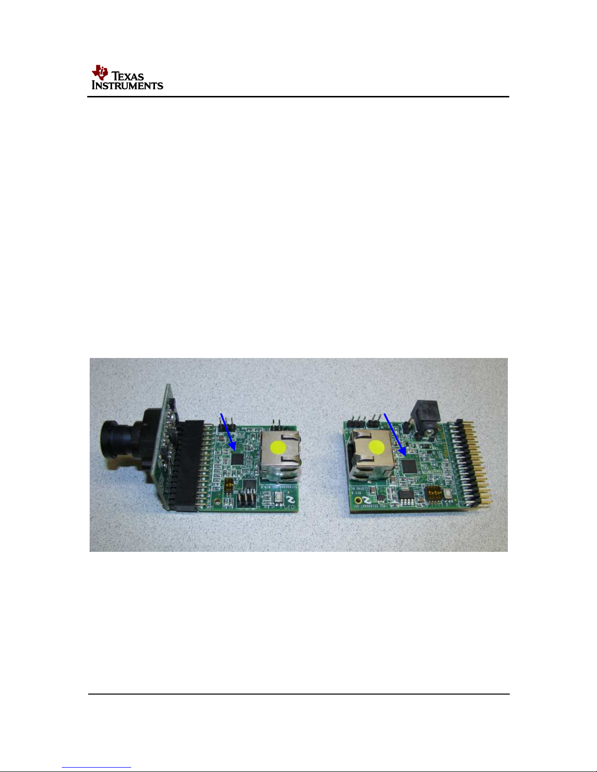
Figure 1: Imager Sensor – Serializer and Deserializer Board Connections
OVT
SER DES
+5VDC
Kit Contents
Page 4

4 SERDESUB-16OVT EVM User’s Guide SNLU108 – July 2012
4. SETUP INSTRUCTIONS
1. Connect the DS90UB901Q Serializer board to the Omnivision module via the J1
32-pin header (16 x 2 x 0.1"). Ensure that the camera module and the Serializer
board are connected properly by matching the ground (GND) pins.
2. Connect the DS90UB902Q Deserializer board to the Host Controller.
3. Connect the DS90UB901Q Serializer board to the DS90UB902Q Deserializer
board via CAT6 cable on the RJ45 connectors.
4. Apply 5V power supply to the Deserializer board J10 power jack.
5. Push “ON” button (S4) on Deserializer board. Green light should now be visible
on RJ45 connectors at Serializer (J4) board and Deserializer (J7) board to
indicate power is applied to the boards.
6. Initialize the Deserializer. Refer to the DS90UB901Q/902Q datasheet for startup
procedure and the definition of each register.
7. Verify that LOCK LED on D5 and the RJ45 orange lights are lit. This indicates the
chipset is Locked and ready to begin I2C communication with the image sensor.
8. Initialize the OmniVision image sensor. Refer to the appropriate sensor
datasheet for specific information.
9. Start video capture (or alternate control application).
Setup Instructions
Page 5
SNLU108 – July 2012 SERDESUB-16OVT EVM User’s Guide 5
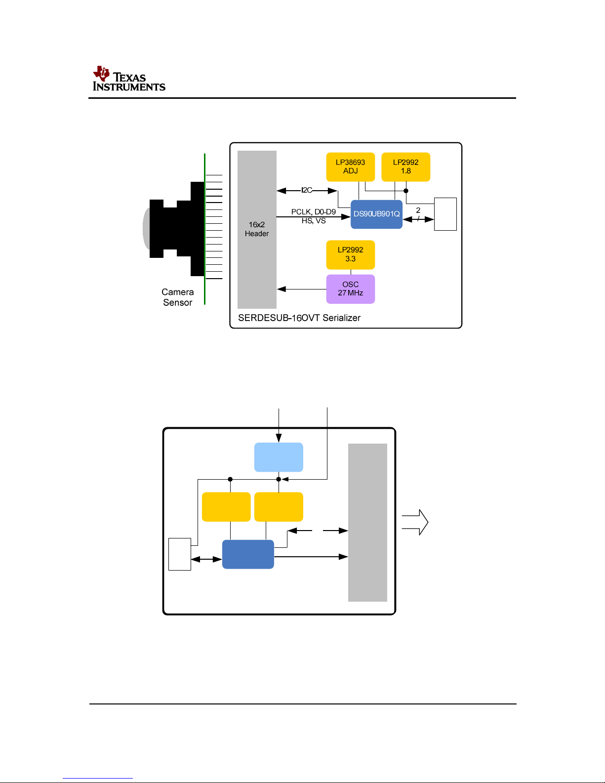
5. BLOCK DIAGRAMS
RJ45
Figure 2. Serializer Board Block Diagram
LP2992
1.8
RJ45
16x2
Header
2
/
I2C
PCLK, D0-D9
HS, VS
SERDESUB-16OVT Deserializer
DS90UB902Q
LM22671
5.0
LP38693
ADJ
12V 5V
To Processor
Figure 3. Deserializer Board Block Diagram
Block Diagrams
Page 6

6 SERDESUB-16OVT EVM User’s Guide SNLU108 – July 2012
6. OPERATION
This section describes how to I2C instructions between Host and image sensor through
the DS90UB902Q and DS90UB901Q pair function in a camera system application.
Figure 4 shows the configuration of evaluation boards for I2C communication with a
Host controller. Note a Host controller requires an I2C interface with slave clock
stretching support.
In Camera mode, I2C transactions originate from the Master controller at the
Deserializer side (Figure 4). The I2C slave core in the Deserializer will detect if a
transaction is intended for the Serializer or the camera sensor (slave device) at the
Serializer. Commands are sent over the bidirectional control channel to initiate the
transactions. The Serializer will receive the command and generate an I2C transaction
on its local I2C bus. At the same time, the Serializer will capture the response on the
I2C bus and return the response on the high speed forward channel. The Deserializer
parses the response and passes the appropriate response onto the Deserializer I2C
bus.
Figure 4. Typical System Block Diagram
Operation
Page 7

SNLU108 – July 2012 SERDESUB-16OVT EVM User’s Guide 7
TROUBLESHOOTING CHART
Problem…
Solution…
No image Check that RJ45 green lights are on
No green light on RJ45
connectors
Check that 5V power supply is applied, and CAT
cable connection is good
Cycle “ON” button on Deserializer
board
All lights on, but no image Check that orientation of board
connections is correct
No image Check that lens cap is removed from
camera
Power, ground, input data and
input clock are connected
correctly, but no outputs.
Check the Power Down pins of both Serializer and
Deserializer boards to make sure that the devices are
enabled (PDB=Vdd) for operation.
Operation
Page 8

8 SERDESUB-16OVT EVM User’s Guide SNLU108 – July 2012
7. BOM (BILL OF MATERIALS)
Item Quantity Reference Part PCB Footprint
______________________________________________________________________________________
1
1
C1 5pF_open CAP_HDC_0603
2
1
C2 5pF_open CAP_HDC_0603
3
5
C3,C4,C5,C28,C29 0.1uF CAP_HDC_0603
4
2
C6,C30 10uF CAP_HDC_0603
5
3
C7,C35,C52 1uF CAP_HDC_0603
6
9
C8,C16,C18,C57,C59,C70, 10uF CAP_HDC_1206
C72,C73,C75
7
1
C9 10uF CAP_HDC_1206
8
14
C10,C11,C13,C19,C20,C22, 0.01uF CAP_HDC_0603
C24,C31,C32,C36,C38,C43,
C47,C60
9
25
C12,C14,C15,C17,C21,C23, 0.1uF CAP_HDC_0603
C25,C33,C37,C39,C44,C45,
C46,C48,C51,C53,C55,C56,
C58,C61,C63,C64,C69,C71,
C74
10
2
C26,C27 100pF CAP_HDC_0603
11
1
C34 22uF 805
12
1
C40 22uF Radial_Surface_Mount
13
1
C41 0.1uF CAP_0603
14
1
C42 1uF CAP_HDC_0805
15
1
C49 100uF 3216_12_EIA_1206
16
1
C50 0.01uF CAP_HDC_0603
17
2
C54,C62 10uF CAP_HDC_0805
18
4
C65,C66,C67,C68 4.7uF CAP_HDC_0805
19
1
D1 Green_LED,0603 603
20
1
D2 DIODE SCHOTTKY SC_90_SOD_323F
21
2
D3,D4 DIODE SCHOTTKY S_Mini_2P
22
1
D5 Orange_LED,0603 603
23
1
J1 HEADER 16X2 Through_Hole_Right_Angle
24
2
J2,J6 IDC1X3 Header_1X3P
25
1
J3 2x3-Pin Header Header_2X3P
26
2
J4,J7 RJ45 RJ45_LED
27
1
J5 HEADER 16X2 hdr_100mil_16X2
28
3
J8,J9,J11 CON2 CON2
29
1
J10 CONN JACK PWR 3_terminal_thru_hole_power_jack
30
1
L1 39uH Surface_Mount_
31
1
L2 100uH 100uH
32
11
L3,L4,L5,L6,L7,L8,L9,L10, FB 1000 Ohm,0402 RES_HDC-0402
L11,L12,L13
33
1
P1 HSD_2X2_open CON_HSD-4P_1
34
1
P2 HSD_2X2_open CON_HSD-4P
35
2
Q1,Q2 MN1382N SC_75
36
1
Q3 PMOSFET PMOSFET
Bill of Materials
Page 9

SNLU108 – July 2012 SERDESUB-16OVT EVM User’s Guide 9
Item Quantity Reference Part PCB Footprint
______________________________________________________________________________________
37
9
R1,R10,R12,R15,R32,R33, 10K
RES_0603
R35,R37,R46
38
4
R2,R3,R19,R29 4.7K RES_0603
39
6
R4,R18,R20,R28,R31,R41 220 ohm RES_0603
40
9
R5,R7,R8,R9,R23,R24,R25, 33 ohm RES_0603
R26,R27
41
1
R6 33 ohm RES_0603
42
5
R11,R13,R34,R36,R38 1.0K RES_0603
43
1
R14 1K RES_0603
44
2
R16,R17 33 ohm_open RES_0603
45
2
R21,R22 1.8K RES_0603
46
2
R30,R54 75 ohm,0603 RES_0603
47
1
R39 0 Ohm RES_HDC_0603
48
1
R40 1.0K_open RES_0603
49
1
R42 0ohm RES_HDC_0603
50
1
R43 976_open RES_HDC_0603
51
1
R44 10K RES_HDC_0402
52
1
R45 470K RES_HDC_060
53
2
R47,R51 9.31K RES_HDC_0603
54
2
R48,R52 5.62K RES_HDC_0603
55
2
R49,R53 51K RES_HDC_0603
56
1
R50 0ohm_open RES_HDC_0603
57
2
R58,R59 0 ohm_open RES_0402
58
1
S1 SW DIP-2 Surface_Mount
59
2
S2,S4 SW PUSHBUTTON SPST_NO
60
1
S3 SW DIP-4 CT2184LPST
61
1
U1 DS90UB901Q 32ld_LLP
62
1
U2 ATtiny25 8_SOIC
63
2
U3,U7 MN1382N, 3.4-3.7V Mini_3P
64
1
U4 LP2992AIM5-3.3 SOT_23_5
65
2
U5,U11 LP2992AIM5-1.8 SOT_23_5
66
1
U6 DS90UB902Q 40ld_LLP
67
1
U8 LM22671MRE-5.0 8_PSOP
68
1
U9 NC7SZ14/SOT23 SC70_5
69
1
U10 NC7SZ74 US8_8_VSSOP
70
2
U12,U13 LP38693MP-ADJ SOT223-4
71
1
Y1 OSC4/SM 4_PIN_SMT
Bill of Materials
Page 10

10 SERDESUB-16OVT EVM User’s Guide SNLU108 – July 2012
8. APPENDIX
Serializer and Deserializer PCB Schematics
Appendix
Page 11

SNLU108 – July 2012 SERDESUB-16OVT EVM User’s Guide 11
Page 12

12 SERDESUB-16OVT EVM User’s Guide SNLU108 – July 2012
Page 13

SNLU108 – July 2012 SERDESUB-16OVT EVM User’s Guide 13
Page 14

14 SERDESUB-16OVT EVM User’s Guide SNLU108 – July 2012
Page 15

SNLU108 – July 2012 SERDESUB-16OVT EVM User’s Guide 15
Page 16

FCC Warning
This evaluation board/kit is intended for use for ENGINEERING DEVELOPMENT, DEMONSTRATION, OR EVALUATION
PURPOSES ONLY and is not considered by TI to be a finished end-product fit for general customer use. It generates, uses, and
can radiate radio frequency energy and has not been tested for compliance with the limits of computing devices pursuant to part 15
of FCC rules, which are designed to provide reasonable protection against radio frequency interference. Operation of this equipment
in other environments may cause interference with radio communications, in which case the user at his own expense will be
required to take whatever measures may be required to correct this interference.
EVALUATION BOARD/KIT IMPORTANT NOTICE
Texas Instruments (TI) provides the enclosed product(s) under the following conditions:
This evaluation board/kit is intended for use for ENGINEERING DEVELOPMENT, DEMONSTRATION, OR EVALUATION
PURPOSES ONLY and is not considered by TI to be a finished end-product fit for general consumer use. Persons handling the
product(s) must have electronics training and observe good engineering practice standards. As such, the goods being provided are
not intended to be complete in terms of required design-, marketing-, and/or manufacturing-related protective considerations,
including product safety and environmental measures typically found in end products that incorporate such semiconductor
components or circuit boards. This evaluation board/kit does not fall within the scope of the European Union directives regarding
electromagnetic compatibility, restricted substances (RoHS), recycling (WEEE), FCC, CE or UL, and therefore may not meet the
technical requirements of these directives or other related directives.
Should this evaluation board/kit not meet the specifications indicated in the User’s Guide, the board/kit may be returned within 30
days from the date of delivery for a full refund. THE FOREGOING WARRANTY IS THE EXCLUSIVE WARRANTY MADE BY
SELLER TO BUYER AND IS IN LIEU OF ALL OTHER WARRANTIES, EXPRESSED, IMPLIED, OR STATUTORY, INCLUDING
ANY WARRANTY OF MERCHANTABILITY OR FITNESS FOR ANY PARTICULAR PURPOSE.
The user assumes all responsibility and liability for proper and safe handling of the goods. Further, the user indemnifies TI from all
claims arising from the handling or use of the goods. Due to the open construction of the product, it is the user’s responsibility to
take any and all appropriate precautions with regard to electrostatic discharge.
EXCEPT TO THE EXTENT OF THE INDEMNITY SET FORTH ABOVE, NEITHER PARTY SHALL BE LIABLE TO THE OTHER
FOR ANY INDIRECT, SPECIAL, INCIDENTAL, OR CONSEQUENTIAL DAMAGES.
TI currently deals with a variety of customers for products, and therefore our arrangement with the user is not exclusive.
TI assumes no liability for applications assistance, customer product design, software performance, or infringement of
patents or services described herein.
Please read the User’s Guide and, specifically, the Warnings and Restrictions notice in the User’s Guide prior to handling the
product. This notice contains important safety information about temperatures and voltages. For additional information on TI’s
environmental and/or safety programs, please contact the TI application engineer or visit www.ti.com/esh.
No license is granted under any patent right or other intellectual property right of TI covering or relating to any machine, process, or
combination in which such TI products or services might be or are used.
EVM WARNINGS AND RESTRICTIONS
Exceeding the specified input range may cause unexpected operation and/or irreversible damage to the EVM. If there are questions
concerning the input range, please contact a TI field representative prior to connecting the input power.
Applying loads outside of the specified output range may result in unintended operation and/or possible permanent damage to the
EVM. Please consult the EVM User's Guide prior to connecting any load to the EVM output. If there is uncertainty as to the load
specification, please contact a TI field representative.
During normal operation, some circuit components may have case temperatures greater than 85° C. The EVM is designed to
operate properly with certain components above 60° C as long as the input and output ranges are maintained. These components
include but are not limited to linear regulators, switching transistors, pass transistors, and current sense resistors. These types of
devices can be identified using the EVM schematic located in the EVM User's Guide. When placing measurement probes near
these devices during operation, please be aware that these devices may be very warm to the touch.
Mailing Address: Texas Instruments, Post Office Box 655303, Dallas, Texas 75265
Copyright © 2012, Texas Instruments Incorporated
Page 17

IMPORTANT NOTICE FOR TI REFERENCE DESIGNS
Texas Instruments Incorporated ("TI") reference designs are solely intended to assist designers (“Buyers”) who are developing systems that
incorporate TI semiconductor products (also referred to herein as “components”). Buyer understands and agrees that Buyer remains
responsible for using its independent analysis, evaluation and judgment in designing Buyer’s systems and products.
TI reference designs have been created using standard laboratory conditions and engineering practices. TI has not conducted any
testing other than that specifically described in the published documentation for a particular reference design. TI may make
corrections, enhancements, improvements and other changes to its reference designs.
Buyers are authorized to use TI reference designs with the TI component(s) identified in each particular reference design and to modify the
reference design in the development of their end products. HOWEVER, NO OTHER LICENSE, EXPRESS OR IMPLIED, BY ESTOPPEL
OR OTHERWISE TO ANY OTHER TI INTELLECTUAL PROPERTY RIGHT, AND NO LICENSE TO ANY THIRD PARTY TECHNOLOGY
OR INTELLECTUAL PROPERTY RIGHT, IS GRANTED HEREIN, including but not limited to any patent right, copyright, mask work right,
or other intellectual property right relating to any combination, machine, or process in which TI components or services are used.
Information published by TI regarding third-party products or services does not constitute a license to use such products or services, or a
warranty or endorsement thereof. Use of such information may require a license from a third party under the patents or other intellectual
property of the third party, or a license from TI under the patents or other intellectual property of TI.
TI REFERENCE DESIGNS ARE PROVIDED "AS IS". TI MAKES NO WARRANTIES OR REPRESENTATIONS WITH REGARD TO THE
REFERENCE DESIGNS OR USE OF THE REFERENCE DESIGNS, EXPRESS, IMPLIED OR STATUTORY, INCLUDING ACCURACY OR
COMPLETENESS. TI DISCLAIMS ANY WARRANTY OF TITLE AND ANY IMPLIED WARRANTIES OF MERCHANTABILITY, FITNESS
FOR A PARTICULAR PURPOSE, QUIET ENJOYMENT, QUIET POSSESSION, AND NON-INFRINGEMENT OF ANY THIRD PARTY
INTELLECTUAL PROPERTY RIGHTS WITH REGARD TO TI REFERENCE DESIGNS OR USE THEREOF. TI SHALL NOT BE LIABLE
FOR AND SHALL NOT DEFEND OR INDEMNIFY BUYERS AGAINST ANY THIRD PARTY INFRINGEMENT CLAIM THAT RELATES TO
OR IS BASED ON A COMBINATION OF COMPONENTS PROVIDED IN A TI REFERENCE DESIGN. IN NO EVENT SHALL TI BE
LIABLE FOR ANY ACTUAL, SPECIAL, INCIDENTAL, CONSEQUENTIAL OR INDIRECT DAMAGES, HOWEVER CAUSED, ON ANY
THEORY OF LIABILITY AND WHETHER OR NOT TI HAS BEEN ADVISED OF THE POSSIBILITY OF SUCH DAMAGES, ARISING IN
ANY WAY OUT OF TI REFERENCE DESIGNS OR BUYER’S USE OF TI REFERENCE DESIGNS.
TI reserves the right to make corrections, enhancements, improvements and other changes to its semiconductor products and services per
JESD46, latest issue, and to discontinue any product or service per JESD48, latest issue. Buyers should obtain the latest relevant
information before placing orders and should verify that such information is current and complete. All semiconductor products are sold
subject to TI’s terms and conditions of sale supplied at the time of order acknowledgment.
TI warrants performance of its components to the specifications applicable at the time of sale, in accordance with the warranty in TI’s terms
and conditions of sale of semiconductor products. Testing and other quality control techniques for TI components are used to the extent TI
deems necessary to support this warranty. Except where mandated by applicable law, testing of all parameters of each component is not
necessarily performed.
TI assumes no liability for applications assistance or the design of Buyers’ products. Buyers are responsible for their products and
applications using TI components. To minimize the risks associated with Buyers’ products and applications, Buyers should provide
adequate design and operating safeguards.
Reproduction of significant portions of TI information in TI data books, data sheets or reference designs is permissible only if reproduction is
without alteration and is accompanied by all associated warranties, conditions, limitations, and notices. TI is not responsible or liable for
such altered documentation. Information of third parties may be subject to additional restrictions.
Buyer acknowledges and agrees that it is solely responsible for compliance with all legal, regulatory and safety-related requirements
concerning its products, and any use of TI components in its applications, notwithstanding any applications-related information or support
that may be provided by TI. Buyer represents and agrees that it has all the necessary expertise to create and implement safeguards that
anticipate dangerous failures, monitor failures and their consequences, lessen the likelihood of dangerous failures and take appropriate
remedial actions. Buyer will fully indemnify TI and its representatives against any damages arising out of the use of any TI components in
Buyer’s safety-critical applications.
In some cases, TI components may be promoted specifically to facilitate safety-related applications. With such components, TI’s goal is to
help enable customers to design and create their own end-product solutions that meet applicable functional safety standards and
requirements. Nonetheless, such components are subject to these terms.
No TI components are authorized for use in FDA Class III (or similar life-critical medical equipment) unless authorized officers of the parties
have executed an agreement specifically governing such use.
Only those TI components that TI has specifically designated as military grade or “enhanced plastic” are designed and intended for use in
military/aerospace applications or environments. Buyer acknowledges and agrees that any military or aerospace use of TI components that
have not been so designated is solely at Buyer's risk, and Buyer is solely responsible for compliance with all legal and regulatory
requirements in connection with such use.
TI has specifically designated certain components as meeting ISO/TS16949 requirements, mainly for automotive use. In any case of use of
non-designated products, TI will not be responsible for any failure to meet ISO/TS16949.
Mailing Address: Texas Instruments, Post Office Box 655303, Dallas, Texas 75265
Copyright © 2014, Texas Instruments Incorporated
Page 18

Mouser Electronics
Authorized Distributor
Click to View Pricing, Inventory, Delivery & Lifecycle Information:
Texas Instruments:
SERDESUB-16OVT/NOPB
 Loading...