

Page 1
Getting started with the new PSpice® for TI
design and simulation tool
Ian Williams
APP – LP – LDO
Page 2

About me – Ian Williams
Business lead, Low-Voltage LDOs
• Career
– BSEE University of Texas at Dallas, 2009
– TI since 2009, LDO since July 2020
• Expertise
– 11 years working with various types of amplifiers
– Co-creator of GWL amplifier SPICE model architecture
– Co-creator of TI Precision Labs – Op Amps
• Fun fact
– Big music guy – have performed at festivals, DJ’d at
clubs and on FM radio, and even met my wife at
Coachella 2013
2
Page 3
Agenda
• TI simulation tools overview – 10 min.
• PSpice® for TI deep dive – 10 min.
– Features and limitations
– Built-in model library
• Setup and simulation examples – 25 min.
– Operational amplifier: OPA211
– Power supply: TPS7A52
– Modeling Application: Power MOSFET
• Additional resources
?
?
Please ask your questions
in the chat!
?
3
Page 4

Part 1
TI simulation tools overview
Tip: SPICE stands for “Simulation Program
with Integrated Circuit Emphasis”
4
Page 5
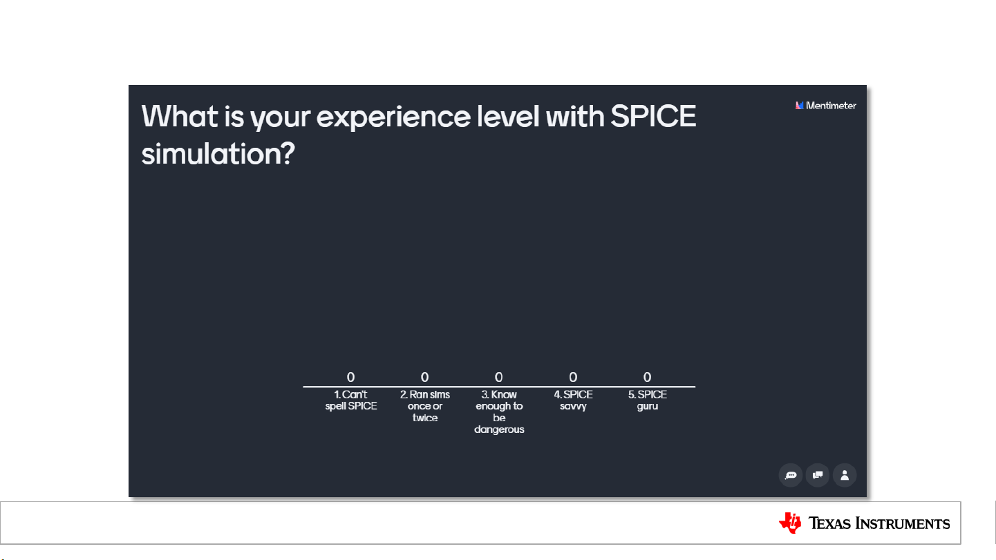
Time for some audience participation…
5
Page 6

Introducing PSpice® for TI
PSpice for TI will help engineers speed time to
market and reduce development costs, delivering:
• Full-featured simulation of entire systems.
– Advanced capabilities, including Monte Carlo and
worst-case analysis.
– Synchronized library of >5,700 models and counting.
– No design size limitations.
– Easy transition to layout and prototype.
• Integrated design resources.
– Quick access to TI product information.
– No need to manually upload new TI models.
6
Page 7
Why is TI partnering with Cadence?
Short design timelines
Today’s design engineers must
produce accurate designs on tight
deadlines — in many cases,
reducing the prototyping and
evaluation phases of their designs.
Growing demand
There is an increased need for
simulation software to test new
design concepts, accelerate product
development and demonstrate
regulatory compliance.
Source: ABI Research
“Tools that are intuitive and include system-level simulation capabilities can
cut the development time and speed time to market.” – Kevin Anderson, Omdia
Desire for more
advanced simulation
Existing simulation tools in the
market lack advanced analysis
capabilities, model portability and
flexibility, and easy library
synchronization.
7
Page 8
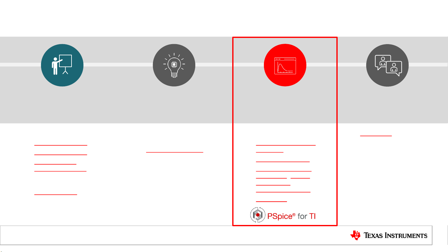
Is PSpice for TI replacing other TI tools?
Fundamentals
& skill-building
• Educational e-books
• Technical articles
• TI Precision Labs
• Power Supply
Design Seminars
(PSDS)
• Additional videos at
training.ti.com
Investigation &
brainstorming
• Easy part selection
on TI.com
• Reference designs
for specific
applications
• Application notes
and technical white
papers
Design &
simulation
• Evaluation modules
• WEBENCH® Power
Designer
• Filter Design Tool
• Analog Engineer’s
Calculator, Circuit
Cookbooks &
Pocket Reference
• TINA-TI™
Design
support
• e2e.ti.com
• Forums for expert
answers to technical
questions
8
Page 9
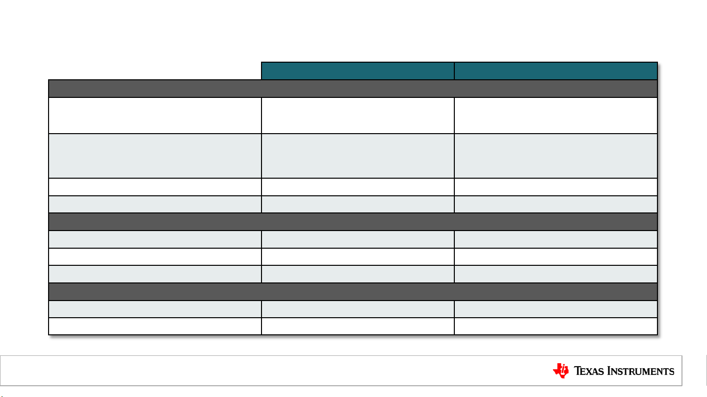
PSpice for TI vs. TINA-TI
Analysis / simulation
AC, Noise, BIAS point, DC sweep,
Transient, Fourier
Variable sweeps
Monte Carlo analysis
Worst case analysis
Libraries / components
Internal libraries
Automatic library updates
in modeling application
Schematics
Create hierarchical schematic
Multipage schematics
PSpice for TI TINA-TI
Yes Yes
Built-
Temperature,
component,
parametric
Yes No
Yes No
~5700 ~1300
Yes No
Yes No
Yes No
Yes No
Temperature,
component
9
Page 10

Part 2
PSpice for TI deep dive
Tip: PSpice for TI runs offline!
10
Page 11

Software features and limitations FAQ
Q. Does PSpice for TI work offline?
A. Yes, an internet connection is not required to run.
Q. Is there a maximum number of nodes?
A. No, there are no design size limitations. You can also use multi-page schematics and
hierarchical blocks.
Q. Are there any other limits to be aware of?
A. Yes. The tool is designed primarily as a SPICE simulation environment for use with the built-in TI
models. If third-party models are imported, then only three nodes can be probed simultaneously.
11
Page 12

Built-in TI model library
Matches the product
tree on TI.com
Includes device-specific test benches
To accelerate your development
12
Page 13

How do I update the TI model library?
• Updates to the model library are automatically detected and performed at
software startup.
– The user can choose not to update.
• The model library is installed locally
on the user’s hard drive. Models can be
copied and imported into other tools
if desired.
– Location: C:\SPB_Data\cdssetup\pspTILibDir
13
Page 14

Are models editable?
• Models are text files and may be edited with a text editor (I recommend
Notepad++) from the library directory
– Note: editing TI models breaks their signature, causing the tool to treat them as 3rd-party
• Some models have user-
editable parameters. Editing
these does not break signature.
• If you edit a model and save it
in the same location, it will get
over-written during the next
library update.
Model file example
14
Page 15

Modeling application
• Used to add customizable, parameterized components to your design:
– Power MOSFETs
– Power diodes
– Passives with parasitics
– Independent sources
– Switches
– Transformers
• Click Place PSpice Component…
Modeling Application in the top
menu bar
• Note: these components do not
trigger the probe limit
15
Page 16

Modeling application, cont.
• A simple UI opens for each type of component with editable fields
• Customize each parameter to your liking, then click Place to drop in schematic
– Note: Device parameters can still be edited from their properties once in the schematic
Power MOSFET window Power NMOS in schematic
16
Page 17

Additional included model libraries
Description
Analog behavioral models for various math functions
Passives, dependent sources, switches, transmission lines
Customizable versions of many device types
Digital timing control, pull
Logic gates, flip
Independent voltage and current sources
Parameters, simulation control, library management, utilities
• These standard PSpice libraries are also included:
Library
ABM
ANALOG
BREAKOUT
DIG_MISC
-up / pull-down resistors
DIG_PRIM
-flops
SOURCE
• Note: components from these libraries do not trigger the probe limit
SPECIAL
17
Page 18

Importing third-party or custom models
• With your project (.opj) selected, click Tools Generate Part
• Browse to your model file in the new window, make your selections, and click OK
• The new model appears in your project’s library
18
Page 19

Types of models on TI.com
Description
Analog / mixed
in a way to be easy to import and use in PSpice / Cadence / OrCAD.
Analog / mixed
in a way to be easy to import and use in TINA
Analog / mixed
simulators. HSPICE is
a branch of SPICE similar to PSpice, but models are not directly compatible.
Switch
I/O Buffer Information Specification model, typically used for digital pin timing
analysis. Compatible with a broad range of industry simulators.
Type
-signal model for use in PSpice-based simulators. Packaged
PSpice
TINA-TI
-signal model for use in PSpice-based simulators. Packaged
HSPICE
(uncommon)
SIMPLIS
IBIS
-mode power supply model for use in SIMPLIS.
-signal model for use in HSPICE-based
-TI.
19
Page 20

Part 3
Setup and simulation examples
Tip: Enabling AutoConverge in your sim
profile can fix a broad range of
convergence issues.
20
Page 21

Operational amplifier example – OPA211
Schematic capture
AC simulation result
21
Page 22

Power supply example – TPS7A52
Schematic capture
Transient simulation result
22
Page 23

Modeling Application – Power MOSFET
Schematic capture
DC simulation result
23
Page 24

Part 4
Additional Resources
Tip: Choose the “Last Plot” setting in your
sim profile to preserve results display
settings between runs.
24
Page 25

Additional resources
Hands-on training manual
• Self-guided, step-by-step tutorial that walks
the user through the entire tool workflow
• Includes basic and more advanced
content
• Includes debugging and troubleshooting
• Available from the PSpice for TI start page:
• Click Training Course
25
Page 26

Additional resources, cont.
Overview content
How to simulate complex
analog power and signalchain circuits with
PSpice® for TI
[Link]
PSpice for TI
overview video
[Link]
Technical training videos
[Link to videos]
TI.com/pspice-for-ti
26
Page 27

“Trust, but verify” SPICE models
• Series of articles that covers verifying parameters of amplifier models:
– Part 1: Output impedance
– Part 2: Small-signal bandwidth
– Part 3: Input-referred errors
– Part 4: Noise
Page 28

Direct support from TI
• For tool-related support: Simulation, hardware & system design tools forum
• For specific model or product support: post to that product’s forum
– i.e. For amplifier support, post to the Amplifiers forum
Note: these forums are all supported by TI applications engineers who are
graded on responsiveness and quality of support. You should get an initial reply in
24h.
28
Page 29

SPICE tips – analysis parameters
Effect
Relaxes multiple parameters if
needed to enable convergence
Sets the absolute
nodal currents between DC
iterations
Sets the relative tolerance of the
nodal voltages
iteration compared to the first
Adds
every p
Adds capacitance from every
node to ground
Option Default Relaxed
AutoConverge Off On
ABSTOL 1e-12 1e-10
RELTOL 1e-3 3e-3
GMIN 1e-12 1e-10
CSHUNT 0 1e-15
tolerance of
at each DC
conductance parallel to
-n junction
29
Page 30

SPICE tips – DC path to GND
MID MID
MID MID
IN-_ESD+
IN+_ESD+
IN+_ESD-
IN-_ESD-
R34 250
R35 250
R52 1G
R53 1G
C_CM+ 4e-12
C_CM- 4e-12
C_DIFF 4e-12
IN+
IN-
• Ensure DC path to ground at every node
– Can force a path with large resistors (1T, etc.) that don’t affect electrical performance
– Try to use the smallest value possible
30
Page 31

MID
SW_OL
OL_SENSE
COM
SW+OLN
OLP
OL_SENSE
R31 1
R32 100
C12 10e-12
-
+
I
H3
-
+
I
H2
OLN
OLP
OL_SENSE
SPICE tips – linear circuits
• Design functional blocks with as linear behavior as possible
– Sharp transitions or discontinuities cause issues with convergence checks
– Use R-C filter networks to reduce bandwidth of subcircuits for smooth transitions
– Use voltage inputs and current outputs wherever possible
Voltage inputs Current output
R-C filter slows edges of
subcircuit output
Resistor converts current to
voltage and provides DC
path to GND
31
Page 32

SPICE tips – bounded matrix
MID
VCCS_LIM
VC+
VC- IOUT+
IOUT-
VCCS_LIM_1
R44 1e6
Out
• Keep matrix equations as tightly bounded as possible
– Place limits on gain and buffer stages
– Use only as much gain as required
– Scale resistances to keep node voltages and currents in similar ranges
32
Page 33

SPICE tips – simplified components
V_B
V_B
-+-
+
VCVS 2 1
+
V_B+ 5
-
+
-
+
VCVS1 1
+
V_B- 5
V_AV_B- V_B+
D1 D2
V_B
V_B
-+-
+
VCVS 2 1
+
V_B+ 5
-
+
-
+
VCVS1 1
+
V_B- 5
V_AV_B- V_B+
-
+
®
SW- 0
-
+
®
SW+ 0
• Replace complex components with simple approximations if exact component
modeling isn’t necessary
– Example: ideal diode voltage-controlled switch
Diode equation:
33
Page 34

Thank you!
34
Page 35

SLYP725
Page 36

IMPORTANT NOTICE AND DISCLAIMER
TI PROVIDES TECHNICAL AND RELIABILITY DATA (INCLUDING DATASHEETS), DESIGN RESOURCES (INCLUDING REFERENCE
DESIGNS), APPLICATION OR OTHER DESIGN ADVICE, WEB TOOLS, SAFETY INFORMATION, AND OTHER RESOURCES “AS IS”
AND WITH ALL FAULTS, AND DISCLAIMS ALL WARRANTIES, EXPRESS AND IMPLIED, INCLUDING WITHOUT LIMITATION ANY
IMPLIED WARRANTIES OF MERCHANTABILITY, FITNESS FOR A PARTICULAR PURPOSE OR NON-INFRINGEMENT OF THIRD
PARTY INTELLECTUAL PROPERTY RIGHTS.
These resources are intended for skilled developers designing with TI products. You are solely responsible for (1) selecting the appropriate
TI products for your application, (2) designing, validating and testing your application, and (3) ensuring your application meets applicable
standards, and any other safety, security, or other requirements. These resources are subject to change without notice. TI grants you
permission to use these resources only for development of an application that uses the TI products described in the resource. Other
reproduction and display of these resources is prohibited. No license is granted to any other TI intellectual property right or to any third
party intellectual property right. TI disclaims responsibility for, and you will fully indemnify TI and its representatives against, any claims,
damages, costs, losses, and liabilities arising out of your use of these resources.
TI’s products are provided subject to TI’s Terms of Sale (www.ti.com/legal/termsofsale.html) or other applicable terms available either on
ti.com or provided in conjunction with such TI products. TI’s provision of these resources does not expand or otherwise alter TI’s applicable
warranties or warranty disclaimers for TI products.
Mailing Address: Texas Instruments, Post Office Box 655303, Dallas, Texas 75265
Copyright © 2020, Texas Instruments Incorporated
 Loading...