

Page 1

MC-1000WU-20A High-Resolution
B/W Camera
User’s Guide
Literature No. SOCU007
May 1998
Printed on Recycled Paper
Page 2

IMPORTANT NOTICE
T exas Instruments and its subsidiaries (TI) reserve the right to make changes to their products or to discontinue
any product or service without notice, and advise customers to obtain the latest version of relevant information
to verify, before placing orders, that information being relied on is current and complete. All products are sold
subject to the terms and conditions of sale supplied at the time of order acknowledgement, including those
pertaining to warranty, patent infringement, and limitation of liability.
TI warrants performance of its semiconductor products to the specifications applicable at the time of sale in
accordance with TI’s standard warranty. Testing and other quality control techniques are utilized to the extent
TI deems necessary to support this warranty . Specific testing of all parameters of each device is not necessarily
performed, except those mandated by government requirements.
CERT AIN APPLICATIONS USING SEMICONDUCTOR PRODUCTS MA Y INVOLVE POTENTIAL RISKS OF
DEATH, PERSONAL INJURY, OR SEVERE PROPERTY OR ENVIRONMENTAL DAMAGE (“CRITICAL
APPLICATIONS”). TI SEMICONDUCTOR PRODUCTS ARE NOT DESIGNED, AUTHORIZED, OR
WARRANTED TO BE SUITABLE FOR USE IN LIFE-SUPPORT DEVICES OR SYSTEMS OR OTHER
CRITICAL APPLICA TIONS. INCLUSION OF TI PRODUCTS IN SUCH APPLICATIONS IS UNDERST OOD TO
BE FULLY AT THE CUSTOMER’S RISK.
In order to minimize risks associated with the customer’s applications, adequate design and operating
safeguards must be provided by the customer to minimize inherent or procedural hazards.
TI assumes no liability for applications assistance or customer product design. TI does not warrant or represent
that any license, either express or implied, is granted under any patent right, copyright, mask work right, or other
intellectual property right of TI covering or relating to any combination, machine, or process in which such
semiconductor products or services might be or are used. TI’s publication of information regarding any third
party’s products or services does not constitute TI’s approval, warranty or endorsement thereof.
Copyright 1998, Texas Instruments Incorporated
Page 3

About This Manual
This User’s Guide provides installation, operation, and maintenance information for the MC-1000WU-20A black and white video camera.
How to Use This Manual
This document contains the following chapters:
-
-
Preface
Read This First
Chapter 1 – Introduction
Chapter 2 – Specifications
-
Chapter 3 – Installation
-
Chapter 4 – Operation
-
Chapter 5 – CCD Circuit Description
-
Chapter 6 – Cleaning Instructions
-
Appendix A – Functional Block Diagram
-
Appendix B – Timing Diagrams
Refer to the appropriate chapter for more information or for instructions concerning procedures or practices.
Information About Cautions and Warnings
This book may contain cautions and warnings.
This is an example of a caution statement.
A caution statement describes a situation that could potentially
damage your software or equipment.
iii
Page 4

About This Manual
This is an example of a warning statement.
A warning statement describes a situation that could potentially
cause harm to you
.
The information in a caution or a warning is provided for your protection.
Please read each caution and warning carefully.
Trademarks
TI is a trademark of Texas Instruments Incorporated.
iv
Page 5

If Y ou Need Assistance
If You Need Assistance . . .
-
World-Wide Web Sites
TI Online http://www.ti.com
Semiconductor Product Information Center (PIC) http://www.ti.com/sc/docs/pic/home.htm
-
North America, South America, Central America
Product Information Center (PIC) (972) 644-5580
TI Literature Response Center U.S.A. (800) 477-8924
Software Registration/Upgrades (214) 638-0333 Fax: (214) 638-7742
U.S.A. Factory Repair/Hardware Upgrades (281) 274-2285
U.S. T echnical T raining Organization (972) 644-5580
-
Europe, Middle East, Africa
European Product Information Center (EPIC) Hotlines:
Multi-Language Support +33 1 30 70 11 69 Fax: +33 1 30 70 10 32
Email: epic@ti.com
Deutsch +49 8161 80 33 11 or +33 1 30 70 11 68
English +33 1 30 70 11 65
Francais +33 1 30 70 11 64
Italiano +33 1 30 70 11 67
EPIC Modem BBS +33 1 30 70 11 99
European Factory Repair +33 4 93 22 25 40
Europe Customer Training Helpline Fax: +49 81 61 80 40 10
-
Asia-Pacific
Literature Response Center +852 2 956 7288 Fax: +852 2 956 2200
-
Japan
Product Information Center +0120-81-0026 (in Japan) Fax: +0120-81-0036 (in Japan)
+03-3457-0972 or (INTL) 813-3457-0972 Fax: +03-3457-1259 or (INTL) 813-3457-1259
-
Documentation
When making suggestions or reporting errors in documentation, please include the following information that is on the title
page: the full title of the book, the publication date, and the literature number.
Mail: Texas Instruments Incorporated
Technical Documentation Services, MS 702
P.O. Box 1443
Houston, Texas 77251-1443
Note: When calling a Literature Response Center to order documentation, please specify the literature number of the
book.
Read This First
v
Page 6

vi
Page 7

Running Title—Attribute Reference
Contents
1 General Description 1-1. . . . . . . . . . . . . . . . . . . . . . . . . . . . . . . . . . . . . . . . . . . . . . . . . . . . . . . . . . . . .
1.1 Features 1-2. . . . . . . . . . . . . . . . . . . . . . . . . . . . . . . . . . . . . . . . . . . . . . . . . . . . . . . . . . . . . . . . . .
1.2 Introduction 1-3. . . . . . . . . . . . . . . . . . . . . . . . . . . . . . . . . . . . . . . . . . . . . . . . . . . . . . . . . . . . . . . .
1.3 Physical Description 1-4. . . . . . . . . . . . . . . . . . . . . . . . . . . . . . . . . . . . . . . . . . . . . . . . . . . . . . . .
1.4 Equipment Supplied 1-5. . . . . . . . . . . . . . . . . . . . . . . . . . . . . . . . . . . . . . . . . . . . . . . . . . . . . . . .
1.5 Equipment Required But Not Supplied 1-6. . . . . . . . . . . . . . . . . . . . . . . . . . . . . . . . . . . . . . . . .
2 Specifications 2-1. . . . . . . . . . . . . . . . . . . . . . . . . . . . . . . . . . . . . . . . . . . . . . . . . . . . . . . . . . . . . . . . . . .
2.1 Specifications 2-2. . . . . . . . . . . . . . . . . . . . . . . . . . . . . . . . . . . . . . . . . . . . . . . . . . . . . . . . . . . . . .
2.2 Interface Circuit 2-4. . . . . . . . . . . . . . . . . . . . . . . . . . . . . . . . . . . . . . . . . . . . . . . . . . . . . . . . . . . .
3 Installation 3-1. . . . . . . . . . . . . . . . . . . . . . . . . . . . . . . . . . . . . . . . . . . . . . . . . . . . . . . . . . . . . . . . . . . . .
3.1 Interface Assignments 3-2. . . . . . . . . . . . . . . . . . . . . . . . . . . . . . . . . . . . . . . . . . . . . . . . . . . . . . .
3.2 Installation Procedure 3-4. . . . . . . . . . . . . . . . . . . . . . . . . . . . . . . . . . . . . . . . . . . . . . . . . . . . . . .
3.2.1 Mounting the Camera 3-4. . . . . . . . . . . . . . . . . . . . . . . . . . . . . . . . . . . . . . . . . . . . . . . .
3.2.2 Connecting an Auto-Iris Lens 3-4. . . . . . . . . . . . . . . . . . . . . . . . . . . . . . . . . . . . . . . . .
3.2.3 Connecting a Standard Lens 3-4. . . . . . . . . . . . . . . . . . . . . . . . . . . . . . . . . . . . . . . . . .
3.2.4 Connecting the AC/DC Power Supply 3-4. . . . . . . . . . . . . . . . . . . . . . . . . . . . . . . . . .
3.2.5 Connecting the Monitor 3-4. . . . . . . . . . . . . . . . . . . . . . . . . . . . . . . . . . . . . . . . . . . . . . .
3.3 Post-Installation Test 3-5. . . . . . . . . . . . . . . . . . . . . . . . . . . . . . . . . . . . . . . . . . . . . . . . . . . . . . . .
4 Operation 4-1. . . . . . . . . . . . . . . . . . . . . . . . . . . . . . . . . . . . . . . . . . . . . . . . . . . . . . . . . . . . . . . . . . . . . .
4.1 General Operating Procedures 4-2. . . . . . . . . . . . . . . . . . . . . . . . . . . . . . . . . . . . . . . . . . . . . . .
4.1.1 Turn-On Procedure 4-2. . . . . . . . . . . . . . . . . . . . . . . . . . . . . . . . . . . . . . . . . . . . . . . . . .
4.1.2 Turn-Off Procedure 4-2. . . . . . . . . . . . . . . . . . . . . . . . . . . . . . . . . . . . . . . . . . . . . . . . . .
4.1.3 Focusing 4-2. . . . . . . . . . . . . . . . . . . . . . . . . . . . . . . . . . . . . . . . . . . . . . . . . . . . . . . . . . .
4.1.4 Adjusting Image Brightness 4-2. . . . . . . . . . . . . . . . . . . . . . . . . . . . . . . . . . . . . . . . . . .
4.2 External Operation (See Appendix B) 4-3. . . . . . . . . . . . . . . . . . . . . . . . . . . . . . . . . . . . . . . . .
5 CCD Circuit Description 5-1. . . . . . . . . . . . . . . . . . . . . . . . . . . . . . . . . . . . . . . . . . . . . . . . . . . . . . . . .
5.1 The CCD Array 5-2. . . . . . . . . . . . . . . . . . . . . . . . . . . . . . . . . . . . . . . . . . . . . . . . . . . . . . . . . . . . .
6 Cleaning Instructions 6-1. . . . . . . . . . . . . . . . . . . . . . . . . . . . . . . . . . . . . . . . . . . . . . . . . . . . . . . . . . . .
6.1 Cleaning 6-2. . . . . . . . . . . . . . . . . . . . . . . . . . . . . . . . . . . . . . . . . . . . . . . . . . . . . . . . . . . . . . . . . . .
A Functional Block Diagram A-1. . . . . . . . . . . . . . . . . . . . . . . . . . . . . . . . . . . . . . . . . . . . . . . . . . . . . . . .
A.1 Functional Block Diagram A-2. . . . . . . . . . . . . . . . . . . . . . . . . . . . . . . . . . . . . . . . . . . . . . . . . . . .
B Timing Diagrams B-1. . . . . . . . . . . . . . . . . . . . . . . . . . . . . . . . . . . . . . . . . . . . . . . . . . . . . . . . . . . . . . . .
B.1 Timing Diagrams B-2. . . . . . . . . . . . . . . . . . . . . . . . . . . . . . . . . . . . . . . . . . . . . . . . . . . . . . . . . . .
Chapter Title—Attribute Reference
vii
Page 8

Tables
Figures
1–1 MC-1000WU-20A Interface Options and Mode Selection 1-3. . . . . . . . . . . . . . . . . . . . . . . . . . .
2–1 Input Interface Circuit of VD, HD, and MCK 2-4. . . . . . . . . . . . . . . . . . . . . . . . . . . . . . . . . . . . . . .
2–2 Output Interface Circuit of Pixel and Shutter Monitor 2-4. . . . . . . . . . . . . . . . . . . . . . . . . . . . . . .
A–1 Functional Block Diagram A-2. . . . . . . . . . . . . . . . . . . . . . . . . . . . . . . . . . . . . . . . . . . . . . . . . . . . . .
B–1 TV Internal Mode (see Note) B-2. . . . . . . . . . . . . . . . . . . . . . . . . . . . . . . . . . . . . . . . . . . . . . . . . . . .
B–2 TV External Mode B-3. . . . . . . . . . . . . . . . . . . . . . . . . . . . . . . . . . . . . . . . . . . . . . . . . . . . . . . . . . . . .
B–3 The Relationship of Vertical Sync Out and Mechanical Shutter or Strobe Light B-3. . . . . . . .
B–4 The Relationship of Horizontal Drive Input and Video Output B-4. . . . . . . . . . . . . . . . . . . . . . . .
B–5 Shutter Internal Mode B-4. . . . . . . . . . . . . . . . . . . . . . . . . . . . . . . . . . . . . . . . . . . . . . . . . . . . . . . . . .
B–6 Shutter External Mode B-5. . . . . . . . . . . . . . . . . . . . . . . . . . . . . . . . . . . . . . . . . . . . . . . . . . . . . . . . .
B–7 The Relationship of VD Input and HD Input B-5. . . . . . . . . . . . . . . . . . . . . . . . . . . . . . . . . . . . . . .
B–8 HD Input Waveform B-6. . . . . . . . . . . . . . . . . . . . . . . . . . . . . . . . . . . . . . . . . . . . . . . . . . . . . . . . . . .
B–9 The Relationship of VD Input and C-Sync B-6. . . . . . . . . . . . . . . . . . . . . . . . . . . . . . . . . . . . . . . .
T ables
2–1 Specifications 2-2. . . . . . . . . . . . . . . . . . . . . . . . . . . . . . . . . . . . . . . . . . . . . . . . . . . . . . . . . . . . . . . .
3–1 Auto Iris Connector Pin Assignment 3-2. . . . . . . . . . . . . . . . . . . . . . . . . . . . . . . . . . . . . . . . . . . . .
3–2 Power Connector Pin Assignment 3-2. . . . . . . . . . . . . . . . . . . . . . . . . . . . . . . . . . . . . . . . . . . . . . .
3–3 Video Connector (BNC Connector) 3-2. . . . . . . . . . . . . . . . . . . . . . . . . . . . . . . . . . . . . . . . . . . . . .
3–4 AUX Connector Pin Assignment 3-3. . . . . . . . . . . . . . . . . . . . . . . . . . . . . . . . . . . . . . . . . . . . . . . .
viii
Page 9

Chapter 1
General Description
This User’s Guide describes installation, operation, and maintenance for the
MC-1000WU-20A video camera.
Topic Page
1.1 Features 1-2. . . . . . . . . . . . . . . . . . . . . . . . . . . . . . . . . . . . . . . . . . . . . . . . . . . . .
1.2 Introduction 1-3. . . . . . . . . . . . . . . . . . . . . . . . . . . . . . . . . . . . . . . . . . . . . . . . . .
1.3 Physical Description 1-4. . . . . . . . . . . . . . . . . . . . . . . . . . . . . . . . . . . . . . . . . .
1.4 Equipment Supplied 1-5. . . . . . . . . . . . . . . . . . . . . . . . . . . . . . . . . . . . . . . . . . .
1.5 Equipment Required But Not Supplied 1-6. . . . . . . . . . . . . . . . . . . . . . . . . .
General Description
1-1
Page 10

Features
1.1 Features
The Texas Instruments MC-1000WU-20A camera features the Texas
Instruments TC215 solid-state monochrome charge-coupled-device (CCD)
image sensor. The camera is for vision system applications requiring highresolution and high-sensitivity operation. The camera features include:
-
TV frame rate, 15 Hz
-
High sensitivity, 0.35 lux typical
-
12 mm square pixel
-
TI-Virtual Phase CCD technology
-
High blue response
-
High near-IR response
-
Electron-hole recombination antiblooming
-
100% optical fill factor
1-2
General Description
Page 11
1.2 Introduction
Introduction
The MC-1000WU-20A is one of a series of high-resolution video cameras that
employs TI’s mega-pixel CCD image sensors. The cameras are intended for
scientific and industrial imaging applications where image data processing is
required.
The MC-1000WU-20A camera employs the TI TC215 full-frame CCD image
sensor, which features 1,017,000 active photosites, resulting in a very-highresolution image. The TC215 sensor provides high sensitivity and good
spectral response as a result of the TI patented Virtual Phase technology.
The TC215 sensor measures 17.2 mm diagonally and features 12-mm square
pixels. The square pixels permit symmetrical image measurement in both the
X and Y axis. The photosite has a 100% fill factor and is responsive to wavelengths in the ultraviolet through the visible and into the near-infrared spectral
regions. The camera outputs composite analog video at a 20-mega-pixel per
second data rate. Two operating options can be selected - a normal operating
mode and a programmable shutter mode. In addition, the camera provides for
auto-iris control.
A mechanical shutter or strobe light is recommended for most
MC-1000WU-20A camera applications. The shutter operation is synchronized
to the camera by supplying an external shutter command signal. The shutter
may operate from a minimum integration time of 1/2500 second to 1/125
second or 10 frames/s maximum. Figure 1–1 shows the camera interface
options and mode selection.
Figure 1–1.MC-1000WU-20A Interface Options and Mode Selection
MCK (20 MHz)
HD
VD
SHT Command
SHT Monitor
Video
Camera Interface Signals
Internal
X’T AL
20 MHz
EXT Pixel
MCK
20 MHz
I/E
80 MHz
Digital
Multiplexer
General Description
1-3
Page 12

Physical Description
1.3 Physical Description
The MC-1000WU-20A camera is housed in an aluminum case 210.6 mm long
(excluding lens) by 68.0 mm high by 68.0 mm wide. It is self-contained except
for power supply and monitor. The camera weighs 2.09 pounds.
The MC-1000WU-20A offers a standard TV C-mount lens attachment with an
adjustable lens locking ring to allow precise adjustment of the lens back focal
length. A variety of lenses or mechanical shutters may be used.
(??Page 3–4 says three ??)Two standard 1/420 threaded tripod mounting
holes on the baseplate allow secure mounting.
1-4
General Description
Page 13

1.4 Equipment Supplied
After unpacking the camera and before discarding the packaging materials,
inventory the shipment for the following items:
-
MC-1000WU-20A CCD camera
-
Lens (optional) (not supplied)(??If not supplied, it won’t be in the inventory??)
-
MC-1000WU-20A CCD Camera User’s Guide
-
Auto iris connector
-
Power connector (optional power supply)
-
I/O interface connector (not supplied)(??If not supplied, it won’t be in
the inventory??)
Equipment Supplied
General Description
1-5
Page 14

Equipment Required But Not Supplied
1.5 Equipment Required But Not Supplied
The MC-1000WU-20A camera uses the full-frame TC215 CCD image sensor.
This full-frame format sensor requires a mechanical shutter or an electronic
light strobe to prevent image smear. The shutter or strobe light allows scene
information to be captured during either the open time of the shutter or on-time
of the strobe light. The transfer or read-out of the captured scene information
is performed during the closed time of the shutter or off-time of the strobe.
Once the shutter or strobe light is chosen, an appropriate lens may also be
selected.
The MC-1000WU-20A camera supplies analog video at either a 15-Hz frame
rate in the TV mode or a 10-Hz frame rate in the shutter mode and can be
displayed directly to a video monitor capable of those frame rates. However,
many applications require the addition of a custom or commercially available
frame-buffer or other video processing equipment. This hardware will enable
the user to capture and digitally process the scene information. The
MC-1000WU-20A is presently supported by several manufacturers of video
processing hardware and software systems. Most manufacturers have
application notes available describing the interface required.
1-6
General Description
Page 15

Chapter 2
Specifications
This chapter lists specifications for the MC-1000WU-20A camera and
describes the interface circuit.
Topic Page
2.1 Specifications 2-2. . . . . . . . . . . . . . . . . . . . . . . . . . . . . . . . . . . . . . . . . . . . . . . .
2.2 Interface Circuit 2-4. . . . . . . . . . . . . . . . . . . . . . . . . . . . . . . . . . . . . . . . . . . . . . .
Specifications
2-1
Page 16

2.1 Specifications
Table 2–1 lists the specifications for the MC-1000WU-20A camera.
Table 2–1.Specifications
Item Specification
Imager Texas Instruments TC215 Full-Frame CCD
Resolution 1024(H)1024(V) (total imager)
1000(H)1017(V) (active pixels)
Pixel size 12 mm12 mm
Imager size H: 12.2 mm
V: 12.0 mm
Synchronization Internal/external (jumper selectable)
TV mode
Shutter mode
Sensitivity 0.29 lux (max)
S/N ratio 48 dB
MTF 10 MHz chart, 35% (typ), 500 nm
White clip 0.90 ±0.05 V
Setup level 50 ±10 mV
Output dc level 0.30 ±0.05 V
Sync level 0.30 ±0.015 V
Supply voltage +5 ±0.15 Vdc
Power consumption (typical) +5 V at 0.820 A
Non-uniformities Total black and white pixel non-uniformities, less than 20. Vertical line non-
Shading (maximum)
Horizontal
Vertical
Vertical frequency 15.46 Hz
Horizontal frequency 16.234 kHz
Gamma
1050 lines/frame (33 blank lines)
15 frames/sec
non-interlace
1050 lines/frame (33 blank lines)
10 frames/sec (max)
0.35 lux (typ)
0.41 lux (min)
1/30 integration
Video output: 100 IRE
S/N ratio: 48 dB
Light source: T=2870°K
–12 ±0.4 Vdc
+12 ±0.4 Vdc
+12 V at 0.180 A
–12 V at 0.150 A
uniformities, less than 5.
10% 100%
15 mV 50 mV
20 mV 70 mV
1.0
2-2
Specifications
Page 17

Table 2–1.Specifications (Continued)
Item Specification
Operating temperature –10_C to +45_C
Storage temperature –30_C to +85_C
Dimensions 68 (W)68 (H)210.6 (D) mm
Weight
2.09 lbs
Specifications
2-3
Page 18

Interface Circuit
2.2 Interface Circuit
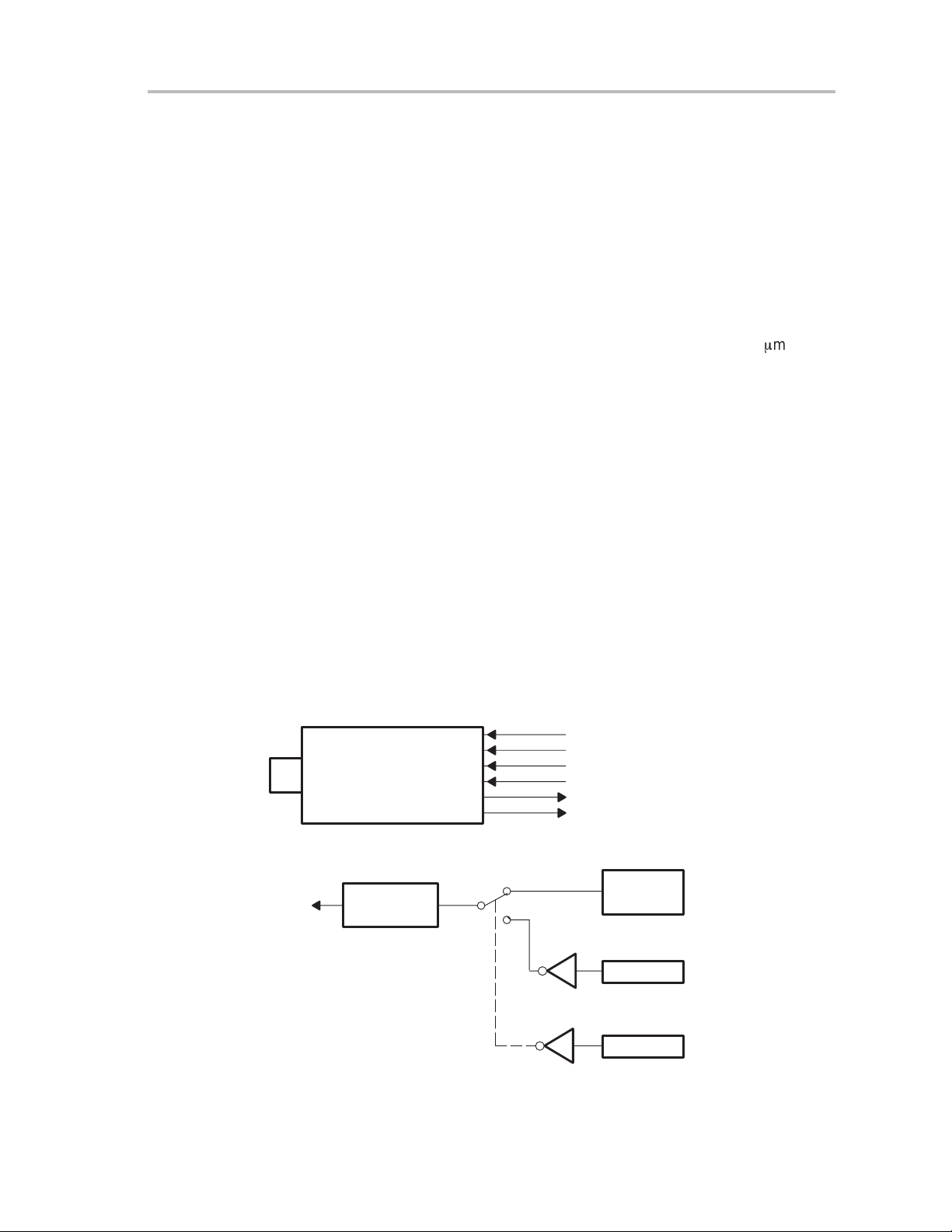
The input interface circuit of VD, HD, and MCK shown in Figure 2–1, consists
of one SN75124 input gate pulled up through a 4.7-kW resistor to 5 Vdc and
pulled down to ground through an optional 100-W resistor. The optional pull
down is selected by jumpers JP1 (MCK), JP2 (HD), and JP3 (VD).
Figure 2–1.Input Interface Circuit of VD, HD, and MCK
VD
4.7 kΩ
JP3
100 Ω
GND
5 V
HD
75124
100 Ω
GND
5 V
4.7 kΩ
MCK
75124
JP2
100 Ω
Figure 2–2.Output Interface Circuit of Pixel and Shutter Monitor
Pixel Out
Shutter
75123
NOTE A. For pixel clock receiving, pull domain resistor 100 Ω is recommended.
470 Ω
Monitor
470 Ω
5 V
4.7 kΩ
75124
JP1
GND
(see Note A)
100 Ω
2-4
Specifications
Page 19

Chapter 3
Installation
This chapter describes interface assignments and gives instructions for
installing and testing the camera.
Topic Page
3.1 Interface Assignments 3-2. . . . . . . . . . . . . . . . . . . . . . . . . . . . . . . . . . . . . . . .
3.2 Installation Procedure 3-4. . . . . . . . . . . . . . . . . . . . . . . . . . . . . . . . . . . . . . . . .
3.3 Post-Installation Test 3-5. . . . . . . . . . . . . . . . . . . . . . . . . . . . . . . . . . . . . . . . . .
Installation
3-1
Page 20

Interface Assignments
3.1 Interface Assignments
Depending upon the application, it may be necessary to build a camera cable
that contains some combination of the signals listed below:
Table 3–1.Auto Iris Connector Pin Assignment
Pin Number Signal Name
A Video signal
B GND
C +12 V
DNC
E
Note: Connectors
Camera side: PRC05-R5M (Tagimi)
Cable side: PRC05-P5F (Tagimi)
Table 3–2.Power Connector Pin Assignment
Pin Number Signal Name
A +12 V
B +12 V
C GND
D +5 V
E +5 V
F GND
G –12 V
H
NC
GND
Note: Connectors
Camera side: R03-R8F (Tagimi)
Cable side: R03-PB8M (Tagimi)
Table 3–3.Video Connector (BNC Connector)
Pin Signal Name
Center pin Composite video
Shell Video RTN
3-2
Installation
Page 21

Table 3–4.AUX Connector Pin Assignment
Pin Signal Name I/O Trigger Interface
1 MCK RTN
2 Horizontal Drive RTN
3 Vertical Drive RTN
4 Pixel Clk Out RTN
5 Shutter RTN
6 Shutter Monitor RTN
7 Internal/External RTN
8 GND
9 MCK IN I SN75124N
10 Horizontal Drive I Negative SN75124N
11 Vertical Drive I Negative SN75124N
12 Pixel Clk Out O SN75123N
Interface Assignments
13 Shutter CMD I SN74LS14N
14 Shutter Monitor OUT O Negative SN75123N
Internal/External I
15
Note: Connector Information
External mode: short 7 pin––––15 pin
Internal mode: open 7 pin––––15 pin
Connectors: Dsub 15 pin female connector, #4-40 (cable side)
Installation
3-3
Page 22

Installation Procedure
3.2 Installation Procedure
The following paragraphs describe installation procedures for the
MC-1000WU-20A camera.
3.2.1 Mounting the Camera
The camera can be mounted using any one of (??T wo on page 1–4??) three
1/420-thread mounting holes located on the camera base plate.
3.2.2 Connecting an Auto-Iris Lens
Most auto-iris lenses can be used with MC-1000 series cameras. Connect the
auto-iris lens to the MC-1000WU-20A camera per the auto-iris connector pinout table in Section 3.1 and the lens wiring schematic provided by the lens
manufacturer.
3.2.3 Connecting a Standard Lens
A number of standard C-mount or shutter attachments may be used with the
camera. The camera employs a lens locking ring to fix the minimum distance
between the rear lens element and the CCD imager.
3.2.4 Connecting the AC/DC Power Supply
The PS-1000 power supply is recommended for use with the camera, because
it already has the proper power connector installed. A bench supply can also
be used, provided that the bench supply output meets the power requirements
of the camera listed in Chapter 2.
3.2.5 Connecting the Monitor
Video may be viewed directly from the camera by attaching a video cable to
the video input jack of a TV monitor. The monitor must be capable of 15 Hz
vertical synchronization. The video may also be the input source to commercially available frame-buffer or other video processing hardware. The video
signal should be properly terminated into a 75-ohm load. A mechanical shutter
or strobe light will be required in most applications.
3-4
Installation
Page 23

3.3 Post-Installation Test
When the power and monitor connections have been made, test the camera
by applying power to the monitor and the external power supply (if used). The
green power-on LED on the camera rear panel should light and an image
should appear on the display . It may be necessary to operate the shutter control or frame-buffer hardware to obtain an image. In addition, the lens may require focus adjustment to obtain a sharp picture.
Post-Installation Test
Installation
3-5
Page 24

3-6
Installation
Page 25

Chapter 4
Operation
This chapter describes general and external operating procedures for the
MC-1000WU-20A camera.
Topic Page
4.1 General Operating Procedures 4-2. . . . . . . . . . . . . . . . . . . . . . . . . . . . . . . . .
4.2 External Operation (See Appendix B) 4-3. . . . . . . . . . . . . . . . . . . . . . . . . . .
Operation
4-1
Page 26

General Operating Procedures
4.1 General Operating Procedures
The MC-1000WU-20A camera features high-resolution, stable, very sensitive,
linear images from an array of 1000(H) by 1017(V) picture elements. The camera operates as one unit of a user-defined imaging system. Other components
typically consist of a mechanical shutter or strobe light, a TV frame-buffer or
frame-storage computer or hardware system, an optical system (lens), and a
power supply . The MC-1000WU-20A camera operates with little or no operator adjustment after the initial setup period. The following paragraphs give operating procedures for the camera.
4.1.1 Turn-On Procedure
The camera does not have a power switch; as soon as power is applied by the
power supply, the camera becomes operable. The green LED on the rear
panel signals that power is applied to the camera. After connection of the
power supply, a picture should appear on a monitor screen within a few
seconds. If additional frame-buffer hardware is used in the application, verify
that the hardware is working properly.
4.1.2 Turn-Off Procedure
T o turn off the camera, remove the power connector from the camera, or switch
off the appropriate system power supply.
4.1.3 Focusing
The MC-1000 series cameras use a lens-locking ring to set the minimum distance between the rear lens element and the CCD imager. Focus the lens by
rotating the front lens barrel clockwise or counterclockwise until the image is
sharp. If a sharp image cannot be obtained, do the following steps:
1) Check lens surface for smears, smudges, or dust. Clean lens surface per
lens manufacturer’s instructions.
2) Check glass cover on CCD imager for smears, smudges, or dust. Clean
glass cover with alcohol and a cotton swab. See Chapter 6, Maintenance
Instructions, for details.
3) Check the distance between the rear lens element and the CCD imager.
If necessary, adjust the distance by loosening the lens-locking ring.
Remember to tighten the lens-locking ring after adjusting to fix the new
distance setting.
4.1.4 Adjusting Image Brightness
Image brightness is a function of exposure time (which is fixed in standard TV
applications) and lens aperture (F number). The sensitivity of the CCD sensor
and the amount of light reaching the sensor through the optical system is a
function of scene illumination, optical alignment, and magnification. In most
cases, the image brightness can be adjusted by varying the lens aperture. If
an image is too dark, rotate the lens aperture ring to a smaller number. This
selects a larger lens aperture, allowing more light through the lens.
4-2
Operation
Page 27

4.2 External Operation (See Appendix B)
-
Figure B–1. TV Internal Mode
-
Figure B–2. TV External Mode
-
Figure B–3. The Relationship of Vertical Sync Out and Mechanical Shutter
or Strobe Light.
-
Figure B–4. The Relationship of Horizontal Drive Input and Video Output
-
Figure B–5. Shutter Internal Mode
-
Figure B–6. Shutter External Mode
-
Figure B–7. The Relationship of VD Input and HD Input
-
Figure B–8. HD Input Waveforms
-
Figure B–9. The Relationship of VD Input and C-Sync
General Operating Procedures
Operation
4-3
Page 28

4-4
Operation
Page 29

Chapter 5
CCD Circuit Description
This chapter describes the TC215 CCD image sensor circuit used in the
camera.
Topic Page
5.1 The CCD Array 5-2. . . . . . . . . . . . . . . . . . . . . . . . . . . . . . . . . . . . . . . . . . . . . . . .
CCD Circuit Description
5-1
Page 30

The CCD Array
5.1 The CCD Array
The TC215 is a full-frame charge-coupled device (CCD) image sensor that
provides very-high-resolution image acquisition for image processing
applications such as robotics vision, medical x-ray analysis, and metrology.
The image format of the sensor measures 12.0 mm horizontally by 12.2 mm
vertically; the image area diagonal is 17.2 mm. The image area contains 1017
active lines with 1000 active pixels per line. Six additional dark reference lines
give a total of 1024 lines in the image area, and twenty-four additional dark
reference pixels per line give a total of 1024 pixels per horizontal line. The
pixels are 12 mm square and form precise rows and columns, horizontally and
vertically, allowing precise image geometry measurements.
The CCD is a solid-state device, which requires no external adjustment or
regular maintenance. Unlike a conventional pickup tube, there are no
electromagnetic alignment routines to be observed because there is no
electron beam involved.
The full-frame image sensor should be used with a shutter or with strobed
illumination to prevent smearing of the image during readout. After image
capture (integration time), the readout is accomplished by transferring the
charge one line at a time into two serial registers, each of which contains 512
data elements and 12 dummy elements. The typical pixel rate is
20 mega-pixels per second using both serial registers. Operating the TC215
at the typical data rate of one field per frame generates video at a continuous
15 frames per second in the TV mode of operation.
5-2
CCD Circuit Description
Page 31

Chapter 6
Cleaning Instructions
This chapter gives instructions for cleaning the camera.
Topic Page
6.1 Cleaning 6-2. . . . . . . . . . . . . . . . . . . . . . . . . . . . . . . . . . . . . . . . . . . . . . . . . . . . .
Cleaning Instructions
6-1
Page 32

Cleaning
6.1 Cleaning
The camera body , lens, and the CCD imager optical glass window should be
kept clean and free of dust and grime. Keeping the lens and the CCD imager
window clean enhances the picture, ensuring better results in the camera
application. These surfaces can be cleaned with denatured alcohol and a
cotton swab. Extreme care should be taken when cleaning the optical glass
CCD imager window to avoid breaking the glass.
6-2
Cleaning Instructions
Page 33

Running Title—Attribute Reference
Appendix A
Functional Block Diagram
This appendix contains the functional block diagram for the camera.
Topic Page
A.1 Functional Block Diagram A-2. . . . . . . . . . . . . . . . . . . . . . . . . . . . . . . . . . . . .
Chapter Title—Attribute Reference
A-1
Page 34

Functional Block Diagram
A.1 Functional Block Diagram
Figure A–1.Functional Block Diagram
3 AM
Interface Board
(20M)
3 AJ
Logic Board
3 AD
CCD Board
3 AK Board
3 AR
Video Process
Board
3 AH
Power/Driver
Board
3 AN
Connector
Board
Power In
Auto IRIS
A-2
Page 35

Running Title—Attribute Reference
Appendix B
Timing Diagrams
This appendix contains timing diagrams for the camera.
Topic Page
B.1 Timing Diagrams B-2. . . . . . . . . . . . . . . . . . . . . . . . . . . . . . . . . . . . . . . . . . . . . .
Chapter Title—Attribute Reference
B-1
Page 36

Timing Diagrams
B.1 Timing Diagrams
Figure B–1.TV Internal Mode (see Note)
1050H
SYNC (Internal)
Mechanical Shutter
†
No output. This timing indicates CCD state which can be the integration. Shutter or strobe timing have to be synchronized
with this window period.
Note: This mode is used for camera operation verification.
Vertical
Shutter
Window
or Strobe Light
Composite
Video (Out)
3H
†
27H
30H
Vertical
Blank
Read Out
1017H
3H
30H
Vertical
Blank
1050H
27H
Read Out
1017H
3H
B-2
Page 37

Figure B–2.TV External Mode
Timing Diagrams
Vertical
Drive (IN)
Vertical
SYNC (Internal)
Shutter
Window
Mechanical Shutter
or Strobe Light
Composite
Video (Out)
30H
Vertical
Blank
1050H 1050H
3H
27H 27H
Read Out
1017H
3H
30H
Vertical
Blank
Read Out
1017H
3H
Figure B–3.The Relationship of Vertical Sync Out and Mechanical Shutter or Strobe Light
Vertical
Drive (IN)
3H 3H
Mechanical Shutter
or Strobe Light
27H 27H
Timing Diagrams
B-3
Page 38

Timing Diagrams
Figure B–4.The Relationship of Horizontal Drive Input and Video Output
HD (Input)
Active
Vedio
Video (Output)
(See B–1–8)
Figure B–5.Shutter Internal Mode
Integrate Frame Read Out Frame
Shutter Command
(Input)
525H 1050H
Shutter Monitor
Vertical SYNC
Shutter Window
Mechanical Shutter
or Strobe Light
†
Fall edge shows starting of CCD integration state. Rise edge shows AB capability state change. The integrate time
does not change, but changes AB capability.
†
(Out)
Flush
(Internal)
Continuous
AB Clock
Recomended Timing For High Dynamic Range XXXX Source Due to The Capability State.
Composite
Video (Out)
30H
Vertical
Blank
Integrate (Flex Timing)
AB Capability High
AB Capability Low
34H
Read Out
1017H
3H
30H
Vertical
Blank
30H
Vertical
Blank
3H
Read Out
1017H
Read Out
1017H
3H
3H
Vertical
Blank
B-4
Page 39

Figure B–6.Shutter External Mode
Integrate Frame Read Out Frame
Shutter Command
(Input)
Timing Diagrams
525H 1050H
Vertical Drive
Shutter Monitor
Vertical SYNC
Shutter Window
Mechanical Shutter
or Strobe Light
(IN)
(Out)
(Internal)
Composite
Video (Out)
Integrate
Flush
34H
For High Dynamic Range Input.
30H
Vertical
Blank
525H
30H
Vertical
Blank
3H
Vertical
Blank
Figure B–7.The Relationship of VD Input and HD Input
TV External Mode
VD (Input)
30H
Read Out
1017H
Read Out
1017H
3H
Vertical
Blank
3H
HD (Input)
SHUTTER (Input)
VD (Input)
HD (Input)
± 50 ns
Shutter External Mode
5 to 50 ns
± 50 ns
Shutter Pulse Width
(380 µs to 10 µs)
Timing Diagrams
B-5
Page 40

Timing Diagrams
Figure B–8.HD Input Waveform
1/F (H)
HD (Input)
3 to 10 µs
Figure B–9.The Relationship of VD Input and C-Sync
VD (Input)
C–SYNC
TTL Level
1 to 9H
B-6
Page 41

IMPORTANT NOTICE
T exas Instruments and its subsidiaries (TI) reserve the right to make changes to their products or to discontinue
any product or service without notice, and advise customers to obtain the latest version of relevant information
to verify, before placing orders, that information being relied on is current and complete. All products are sold
subject to the terms and conditions of sale supplied at the time of order acknowledgement, including those
pertaining to warranty, patent infringement, and limitation of liability.
TI warrants performance of its semiconductor products to the specifications applicable at the time of sale in
accordance with TI’s standard warranty. Testing and other quality control techniques are utilized to the extent
TI deems necessary to support this warranty . Specific testing of all parameters of each device is not necessarily
performed, except those mandated by government requirements.
CERT AIN APPLICATIONS USING SEMICONDUCTOR PRODUCTS MA Y INVOLVE POTENTIAL RISKS OF
DEATH, PERSONAL INJURY, OR SEVERE PROPERTY OR ENVIRONMENTAL DAMAGE (“CRITICAL
APPLICATIONS”). TI SEMICONDUCTOR PRODUCTS ARE NOT DESIGNED, AUTHORIZED, OR
WARRANTED TO BE SUITABLE FOR USE IN LIFE-SUPPORT DEVICES OR SYSTEMS OR OTHER
CRITICAL APPLICA TIONS. INCLUSION OF TI PRODUCTS IN SUCH APPLICATIONS IS UNDERST OOD TO
BE FULLY AT THE CUSTOMER’S RISK.
In order to minimize risks associated with the customer’s applications, adequate design and operating
safeguards must be provided by the customer to minimize inherent or procedural hazards.
TI assumes no liability for applications assistance or customer product design. TI does not warrant or represent
that any license, either express or implied, is granted under any patent right, copyright, mask work right, or other
intellectual property right of TI covering or relating to any combination, machine, or process in which such
semiconductor products or services might be or are used. TI’s publication of information regarding any third
party’s products or services does not constitute TI’s approval, warranty or endorsement thereof.
Copyright 1998, Texas Instruments Incorporated
 Loading...