

Page 1

10 mV/Div
500 MHz BW
1 µs/Div
COUT = 10 F 10V 0805 X5R
VOUT RIPPLE
0.0 0.1 0.2 0.3 0.4 0.5 0.6 0.7
20
30
40
50
60
70
80
90
100
EFFICIENCY (%)
LOAD CURRENT (A)
VOUT = 1.2V
VOUT = 1.8V
VOUT = 2.5V
VOUT = 3.3V
LMZ10500
www.ti.com
SNVS723C –OCTOBER 2011–REVISED MARCH 2013
LMZ10500 650mA SIMPLE SWITCHER® Nano Module with 5.5V Maximum Input Voltage
Check for Samples: LMZ10500
1
FEATURES
2
• Integrated Inductor
• Miniature Form Factor (3.0mm x 2.5mm x
1.425mm)
• 8-pin LLP Footprint
• –40°C to 125°C Junction Temperature Range
• Adjustable Output Voltage
• 2.0MHz Fixed PWM Switching Frequency
• Integrated Compensation
• Soft Start Function
• Current Limit Protection
• Thermal Shutdown Protection
• Input Voltage UVLO for Power-up, Powerdown, and Brown-out Conditions
• Only 5 External Components — Resistor
Divider and 3 Ceramic Capacitors
DESCRIPTION
The LMZ10500 SIMPLE SWITCHER® nano module
is an easy-to-use step-down DC-DC solution capable
of driving up to 650mA load in space-constrained
applications. Only an input capacitor, an output
capacitor, a small V
resistors are required for basic operation. The nano
module comes in 8-pin POS footprint package with
an integrated inductor. Internal current limit based
softstart function, current overload protection, and
thermal shutdown are also provided.
System Performance
(Quick Overview Links: V
3.3V)
Typical Efficiency at VIN= 3.6V
filter capacitor, and two
CON
= 1.2V, 1.8V, 2.5V,
OUT
APPLICATIONS
• Point of Load Conversions from 3.3V and 5V
Rails
• Space Constrained Applications
• Low Output Noise Applications
ELECTRICAL SPECIFICATIONS
• Up to 650mA Output Current
• Input Voltage Range 2.7V to 5.5V
• Output Voltage Range 0.6V to 3.6V
• Efficiency up to 95%
PERFORMANCE BENEFITS
• Small Solution Size
• Low output Voltage Ripple
• Easy Component Selection and Simple PCB
Layout
• High Efficiency Reduces System Heat
Generation
1
Please be aware that an important notice concerning availability, standard warranty, and use in critical applications of
Texas Instruments semiconductor products and disclaimers thereto appears at the end of this data sheet.
2All trademarks are the property of their respective owners.
PRODUCTION DATA information is current as of publication date.
Products conform to specifications per the terms of the Texas
Instruments standard warranty. Production processing does not
necessarily include testing of all parameters.
Output Voltage Ripple
VIN= 5.0V, V
Copyright © 2011–2013, Texas Instruments Incorporated
OUT
= 1.8V, I
OUT
= 650mA
Page 2

PAD
PAD
PAD
0 200 400 600 800 1000
0
10
20
30
40
50
60
70
80
RADIATED EMISSIONS (dBV/m)
FREQUENCY (MHz)
Emissions
CISPR 22 Class B Limit
CISPR 22 Class A Limit
LMZ10500
SNVS723C –OCTOBER 2011–REVISED MARCH 2013
VIN= 5.0V, V
Connection Diagram
Radiated EMI (CISPR22)
OUT
= 1.8V, I
= 650mA
OUT
www.ti.com
Pin # Name Description
1 EN Enable Input. Set this digital input higher than 1.2V for normal operation. For shutdown, set low. Pin is
internally pulled up to VIN and can be left floating for always-on operation.
2 VCON Output voltage control pin. Connect to analog voltage from resisitve divider or DAC/controller to set the VOUT
voltage. V
filtering.
OUT
3 FB Feedback of the error amplifier. Connect directly to output capacitor to sense V
4 SGND Ground for analog and control circuitry. Connect to PGND at a single point.
5 VOUT Output Voltage. Connected to one terminal of the integrated inductor. Connect output filter capacitor between
VOUT and PGND.
6 PGND Power ground for the power MOSFETs and gate-drive circuitry.
7 VIN Voltage supply input. Connect ceramic capacitor between VIN and PGND as close as possible to these two
pins. Typical capacitor values are between 4.7µF and 22µF.
8 VREF 2.35V voltage reference output. Typically connected to VCON pin through a resistive divider to set the output
voltage.
PAD The 3 pads underneath the module are not internally connected to any node. These pads should be
connected to the ground plane for improved thermal performance.
2 Submit Documentation Feedback Copyright © 2011–2013, Texas Instruments Incorporated
These devices have limited built-in ESD protection. The leads should be shorted together or the device placed in conductive foam
during storage or handling to prevent electrostatic damage to the MOS gates.
Figure 1. Package Number NQB0008A
Pin Descriptions
= 2.5 x V
. Connect a small (470pF) capacitor from this pin to SGND to provide noise
CON
Product Folder Links: LMZ10500
OUT
.
Page 3

LMZ10500
www.ti.com
Absolute Maximum Ratings
(1)(2)
SNVS723C –OCTOBER 2011–REVISED MARCH 2013
VIN, VREF to SGND −0.2V to +6.0V
PGND to SGND −0.2V to +0.2V
EN, FB, VCON (SGND −0.2V)
to (VIN +0.2V)
w/6.0V max
VOUT (PGND −0.2V)
to (VIN +0.2V)
w/6.0V max
Junction Temperature (T
) +150°C
J-MAX
Storage Temperature Range −65°C to +150°C
Maximum Lead Temperature +260°C
ESD Susceptibility
(3)
±2kV
(1) Absolute Maximum Ratings are limits beyond which damage to the device may occur. Operating Ratings are conditions under which
operation of the device is intended to be functional. For guaranteed specifications and test conditions, see the Electrical Characteristics.
(2) If Military/Aerospace specified devices are required, please contact the Texas Instruments Sales Office/ Distributors for availability and
specifications.
(3) The human body model is a 100pF capacitor discharged through a 1.5 kΩ resistor into each pin. Test method is per JESD-22-114.
Operating Ratings
(1)
Input Voltage Range 2.7V to 5.5V
Recommended Load Current 0 mA to 650mA
Junction Temperature (TJ) Range −40°C to +125°C
(1) Absolute Maximum Ratings are limits beyond which damage to the device may occur. Operating Ratings are conditions under which
operation of the device is intended to be functional. For guaranteed specifications and test conditions, see the Electrical Characteristics.
Thermal Properties
Junction-to-Ambient Thermal 120°C/W
Resistance (θJA), NQB0008A Package
(1)
(1) Junction-to-ambient thermal resistance (θJA) is based on 4 layer board thermal measurements, performed under the conditions and
guidelines set forth in the JEDEC standards JESD51-1 to JESD51-11. θJAvaries with PCB copper area, power dissipation, and airflow.
Electrical Characteristics
Specifications with standard typeface are for TJ= 25°C only; Limits in bold face type apply over the operating junction
temperature range TJof -40°C to 125°C. Minimum and maximum limits are guaranteed through test, design, or statistical
correlation. Typical values represent the most likely parametric norm at TJ= 25°C, and are provided for reference purposes
only. Unless otherwise stated the following conditions apply: VIN= 3.6V, VEN= 1.2V.
Symbol Parameter Conditions Units
SYSTEM PARAMETERS
V
x GAIN Reference voltage x VCON to VIN= VEN= 5.5V, V
REF
GAIN VCON to FB Gain VIN= 5.5V, V
VIN
UVLO
VIN
UVLO
I
SHDN
I
q
R
DROPOUT
FB Gain
VIN rising threshold 2.4 V
VIN falling theshold 2.25 V
Shutdown supply current VIN= 3.6V, VEN= 0.5V
DC bias current into VIN VIN= 5.5V, V
VINto V
(1)
resistance I
OUT
Min Typ Max
(1) (2) (1)
= 1.44V
CON
= 1.44V 2.4375 2.5 2.5750 V/V
CON
(3)
= 1.6V, I
0A
OUT
CON
= 200 mA 285 425 mΩ
OUT
5.7575 5.875 5.9925 V
11 18 µA
=
6.5 8.5 mA
(1) Min and Max limits are 100% production tested at 25°C. Limits over the operating temperature range are guaranteed through correlation
using Statistical Quality Control (SQC) methods. Limits are used to calculate the Average Outgoing Quality Level (AOQL).
(2) Typical numbers are at 25°C and represent the most likely parametric norm.
(3) Shutdown current includes leakage current of the high side PFET.
Copyright © 2011–2013, Texas Instruments Incorporated Submit Documentation Feedback 3
Product Folder Links: LMZ10500
Page 4

LMZ10500
SNVS723C –OCTOBER 2011–REVISED MARCH 2013
Electrical Characteristics
(1)
(continued)
www.ti.com
Specifications with standard typeface are for TJ= 25°C only; Limits in bold face type apply over the operating junction
temperature range TJof -40°C to 125°C. Minimum and maximum limits are guaranteed through test, design, or statistical
correlation. Typical values represent the most likely parametric norm at TJ= 25°C, and are provided for reference purposes
only. Unless otherwise stated the following conditions apply: VIN= 3.6V, VEN= 1.2V.
Symbol Parameter Conditions Units
SYSTEM PARAMETERS
I
LIM
F
OSC
V
IH,ENABLE
V
IL,ENABLE
T
SD
T
SD-HYST
D
MAX
T
ON-MIN
θ
JA
DC Output Current Limit VCON = 0.24V
(4)
Internal oscillator frequency 1.75 2.0 2.25 MHz
Enable logic HIGH voltage 1.2 V
Enable logic LOW voltage 0.5 V
Thermal shutdown Rising Threshold 150 °C
Thermal shutdown hysteresis 20 °C
Maximum duty cycle 100 %
Minimum on-time 50 ns
Package Thermal Resistance 20mm x 20mm board
2 layers, 2 oz copper, 0.5W, no 118
airlow
15mm x 15mm board
2 layers, 2 oz copper, 0.5W, no 132 °C/W
airlow
10mm x 10mm board
2 layers, 2 oz copper, 0.5W, no 157
airlow
(4) Current limit is built-in, fixed, and not adjustable.
Min Typ Max
(1) (2) (1)
800 1000 mA
System Characteristics
The following specifications are guaranteed by design providing the component values in the Typical Application Circuit are
used (CIN= C
testing. Unless otherwise stated the following conditions apply: TA= 25°C.
Symbol Parameter Conditions Min Typ Max Units
ΔV
OUT/VOUT
ΔV
OUT/VOUT
ΔV
OUT/VOUT
VREF T
RISE
η %
V
Ripple Output voltage ripple VIN= 5.0V, V
OUT
Line
Transient
= 10 µF, 6.3V, 0603, TDK C1608X5R0J106K). These parameters are not guaranteed by production
OUT
Output Voltage Regulation Over V
Line Voltage and Load Current ΔVIN=2.7V to 4.2V ±1.23 %
Output Voltage Regulation Over V
Line Voltage and Load Current ΔVIN= 2.7V to 5.5V ±0.56 %
Output Voltage Regulation Over V
Line Voltage and Load Current ΔVIN= 4.0V to 5.5V ±0.24 %
Rise time of reference voltage EN = Low to High, VIN= 4.2V
Peak Efficiency 95
Full Load Efficiency VIN= 5.0V, V
= 0.6V
OUT
ΔI
= 0A to 650mA
OUT
= 1.5V
OUT
ΔI
= 0A to 650mA
OUT
= 3.6V
OUT
ΔI
= 0A to 650 mA
OUT
V
= 2.7V, I
OUT
VIN= 5.0V, V
I
= 200 mA
OUT
I
= 650 mA
OUT
I
= 650 mA
OUT
OUT
OUT
OUT
OUT
(1)
= 650 mA
= 3.3V
= 3.6V
= 1.8V
10 µs
93
8 mV pk-pk
VIN = 2.7V to 5.5V,
Line transient response TR= TF= 10 µs, 25 mV pk-pk
VOUT = 1.8V, I
OUT
= 650 mA
(1) Ripple voltage should be measured across C
4 Submit Documentation Feedback Copyright © 2011–2013, Texas Instruments Incorporated
on a well-designed PC board using the suggested capacitors.
OUT
Product Folder Links: LMZ10500
Page 5

LMZ10500
www.ti.com
SNVS723C –OCTOBER 2011–REVISED MARCH 2013
System Characteristics (continued)
The following specifications are guaranteed by design providing the component values in the Typical Application Circuit are
used (CIN= C
testing. Unless otherwise stated the following conditions apply: TA= 25°C.
Symbol Parameter Conditions Min Typ Max Units
Load TR= TF= 40 µs,
Transient V
= 10 µF, 6.3V, 0603, TDK C1608X5R0J106K). These parameters are not guaranteed by production
OUT
VIN = 5.0V
Load transient response 25 mV pk-pk
= 1.8V
OUT
I
= 65mA to 650mA
OUT
Copyright © 2011–2013, Texas Instruments Incorporated Submit Documentation Feedback 5
Product Folder Links: LMZ10500
Page 6

60 70 80 90 100 110 120 130
0.0
0.1
0.2
0.3
0.4
0.5
0.6
0.7
OUTPUT CURRENT (A)
AMBIENT TEMPERATURE (°C)
VIN = 4.0V
VIN = 4.5V
VIN = 5.0V
VIN = 5.5V
0 200 400 600 800 1000
0
10
20
30
40
50
60
70
80
RADIATED EMISSIONS (dBV/m)
FREQUENCY (MHz)
Emissions
CISPR 22 Class B Limit
CISPR 22 Class A Limit
60 70 80 90 100 110 120 130
0.0
0.1
0.2
0.3
0.4
0.5
0.6
0.7
OUTPUT CURRENT (A)
AMBIENT TEMPERATURE (°C)
VIN = 3.3V
VIN = 3.6V
VIN = 5.0V
VIN = 5.5V
60 70 80 90 100 110 120 130
0.0
0.1
0.2
0.3
0.4
0.5
0.6
0.7
OUTPUT CURRENT (A)
AMBIENT TEMPERATURE (°C)
VIN = 3.3V
VIN = 3.6V
VIN = 5.0V
VIN = 5.5V
0.0 0.1 0.2 0.3 0.4 0.5 0.6 0.7
0.00
0.05
0.10
0.15
0.20
0.25
0.30
0.35
DROPOUT VOLTAGE (V)
LOAD CURRENT (A)
VIN = 2.7V
VIN = 3.3V
VIN = 3.6V
VIN = 4.0V
60 70 80 90 100 110 120 130
0.0
0.1
0.2
0.3
0.4
0.5
0.6
0.7
OUTPUT CURRENT (A)
AMBIENT TEMPERATURE (°C)
VIN = 3.3V
VIN = 3.6V
VIN = 5.0V
VIN = 5.5V
LMZ10500
SNVS723C –OCTOBER 2011–REVISED MARCH 2013
Typical Performance Characteristics
Unless otherwise specified the following conditions apply: VIN= 3.6V, TA= 25°C
Dropout Voltage
Load Current and Input Voltage Thermal Derating V
Thermal Derating V
vs
Figure 2. Figure 3.
= 1.8V, θJA= 120°C/W Thermal Derating V
OUT
= 1.2V, θJA= 120°C/W
OUT
= 2.5V, θJA= 120°C/W
OUT
www.ti.com
Figure 4. Figure 5.
Thermal Derating V
6 Submit Documentation Feedback Copyright © 2011–2013, Texas Instruments Incorporated
= 3.3V, θJA= 120°C/W Default evaluation board BOM
OUT
Figure 6. Figure 7.
Product Folder Links: LMZ10500
Radiated EMI (CISPR22)
VIN= 5.0V, V
OUT
= 1.8V, I
OUT
= 650mA
Page 7
100m 1 10 100
0
10
20
30
40
50
60
70
80
CONDUCTED EMISSIONS (dBV)
FREQUENCY (MHz)
Conducted Emissions
CISPR 22 Quasi Peak
CISPR 22 Average
10 µs/Div
500 mV/Div
500 mV/Div
200 mA/Div
200 mA/Div
VCON
IL
IOUT
VOUT
LMZ10500
www.ti.com
Typical Performance Characteristics (continued)
Unless otherwise specified the following conditions apply: VIN= 3.6V, TA= 25°C
Default evaluation board BOM with additional 1µH 1µF LC
VIN= 5.0V, V
Conducted EMI
OUT
= 1.8V, I
OUT
= 650mA
input filter Startup
Figure 8. Figure 9.
SNVS723C –OCTOBER 2011–REVISED MARCH 2013
Copyright © 2011–2013, Texas Instruments Incorporated Submit Documentation Feedback 7
Product Folder Links: LMZ10500
Page 8
0.0 0.1 0.2 0.3 0.4 0.5 0.6 0.7
1.20
1.21
1.22
1.23
1.24
OUTPUT VOLTAGE (V)
LOAD CURRENT (A)
VIN = 2.7V
VIN = 3.3V
VIN = 3.6V
VIN = 5.0V
VIN = 5.5V
2.5 3.0 3.5 4.0 4.5 5.0 5.5
0.6
0.7
0.8
0.9
1.0
1.1
DC CURRENT LIMIT (A)
INPUT VOLTAGE (V)
TA= 85°C
10 mV/Div
500 MHz BW 1 µs/Div
COUT = 10 F 10V 0805 X5R
VOUT RIPPLE
30 mV/Div
250 MHz BW 500 µs/Div
COUT = 10 F 10V 0805 X5R
LOAD CURRENT
OUTPUT VOLTAGE
500 mA/Div
0.0 0.1 0.2 0.3 0.4 0.5 0.6 0.7
20
30
40
50
60
70
80
90
100
EFFICIENCY (%)
LOAD CURRENT (A)
VIN = 2.7V
VIN = 3.3V
VIN = 3.6V
VIN = 5.0V
VIN = 5.5V
FB
EN
V
REF
SGND
PGND
1.2V
V
OUT
V
IN
C
OUT
C
IN
V
OUT
V
CON
V
IN
C
VC
R
B
R
T
C
IN
C
OUT
C
VC
R
T
R
B
243 k: 1% 0603
63.4 k: 1% 0603
10 P)86.3V 0805 X7R or X5R
10 PF 86.3V 0805 X7R or X5R
470 pF 86.3V 0603 X7R or X5R
LMZ10500
SNVS723C –OCTOBER 2011–REVISED MARCH 2013
Schematic V
= 1.2V Efficiency V
OUT
Figure 10. Figure 11.
Output Ripple V
= 1.2V Load Transient V
OUT
1.2V
OUT
= 1.2V
OUT
www.ti.com
= 1.2V
Figure 12. Figure 13.
Line and Load Regulation V
8 Submit Documentation Feedback Copyright © 2011–2013, Texas Instruments Incorporated
Figure 14. Figure 15.
= 1.2V DC Current Limit V
OUT
Product Folder Links: LMZ10500
OUT
= 1.2V
Page 9

0.0 0.1 0.2 0.3 0.4 0.5 0.6 0.7
1.77
1.78
1.79
1.80
1.81
OUTPUT VOLTAGE (V)
LOAD CURRENT (A)
VIN = 2.7V
VIN = 3.3V
VIN = 3.6V
VIN = 5.0V
VIN = 5.5V
2.5 3.0 3.5 4.0 4.5 5.0 5.5
0.7
0.8
0.9
1.0
1.1
1.2
1.3
DC CURRENT LIMIT (A)
INPUT VOLTAGE (V)
TA= 85°C
30 mV/Div
250 MHz BW 500 µs/Div
COUT = 10 F 10V 0805 X5R
LOAD CURRENT
OUTPUT VOLTAGE
500mA/Div
10 mV/Div
500 MHz BW
1 µs/Div
COUT = 10 F 10V 0805 X5R
VOUT RIPPLE
0.0 0.1 0.2 0.3 0.4 0.5 0.6 0.7
20
30
40
50
60
70
80
90
100
EFFICIENCY (%)
LOAD CURRENT (A)
VIN = 2.7V
VIN = 3.3V
VIN = 3.6V
VIN = 5.0V
VIN = 5.5V
FB
EN
V
REF
SGND
PGND
1.8V
V
OUT
V
IN
C
OUT
C
IN
V
OUT
V
CON
V
IN
C
VC
R
B
R
T
C
IN
C
OUT
C
VC
R
T
R
B
187 k: 1% 0603
82.5 k: 1% 0603
10 P)86.3V 0805 X7R or X5R
10 PF 86.3V 0805 X7R or X5R
470 pF 86.3V 0603 X7R or X5R
LMZ10500
www.ti.com
SNVS723C –OCTOBER 2011–REVISED MARCH 2013
1.8V
Schematic V
Figure 16. Figure 17.
Output Ripple V
= 1.8V Efficiency V
OUT
= 1.8V Load Transient V
OUT
OUT
= 1.8V
OUT
= 1.8V
Figure 18. Figure 19.
Line and Load Regulation V
Copyright © 2011–2013, Texas Instruments Incorporated Submit Documentation Feedback 9
Figure 20. Figure 21.
= 1.8V DC Current Limit V
OUT
Product Folder Links: LMZ10500
OUT
= 1.8V
Page 10

0.0 0.1 0.2 0.3 0.4 0.5 0.6 0.7
2.50
2.50
2.51
2.52
2.53
OUTPUT VOLTAGE (V)
LOAD CURRENT (A)
VIN = 3.3V
VIN = 3.6V
VIN = 5.0V
VIN = 5.5V
2.5 3.0 3.5 4.0 4.5 5.0 5.5
0.7
0.8
0.9
1.0
1.1
1.2
1.3
DC CURRENT LIMIT (A)
INPUT VOLTAGE (V)
TA= 85°C
10 mV/Div
500 MHz BW
1 Ps/Div
COUT = 10 PF 10V 0805 X5R
VOUT RIPPLE
30 mV/Div
250 MHz BW
500 µs/Div
COUT = 10 F 10V 0805 X5R
LOAD CURRENT
OUTPUT VOLTAGE
500 mA/Div
0.0 0.1 0.2 0.3 0.4 0.5 0.6 0.7
20
30
40
50
60
70
80
90
100
EFFICIENCY (%)
LOAD CURRENT (A)
VIN = 3.3V
VIN = 3.6V
VIN = 5.0V
VIN = 5.5V
FB
EN
V
REF
SGND
PGND
2.5V
V
OUT
V
IN
C
OUT
C
IN
V
OUT
V
CON
V
IN
C
VC
R
B
R
T
10 P)86.3V 0805 X7R or X5R
C
IN
C
OUT
C
VC
R
T
R
B
10 PF 86.3V 0805 X7R or X5R
470 pF 86.3V 0603 X7R or X5R
150 k: 1% 0603
118 k: 1% 0603
LMZ10500
SNVS723C –OCTOBER 2011–REVISED MARCH 2013
Schematic V
= 2.5V Efficiency V
OUT
Figure 22. Figure 23.
Output Ripple V
= 2.5V Load Transient V
OUT
2.5V
OUT
= 2.5V
OUT
www.ti.com
= 2.5V
Figure 24. Figure 25.
Line and Load Regulation V
10 Submit Documentation Feedback Copyright © 2011–2013, Texas Instruments Incorporated
Figure 26. Figure 27.
= 2.5V DC Current Limit V
OUT
Product Folder Links: LMZ10500
OUT
= 2.5V
Page 11

0.0 0.1 0.2 0.3 0.4 0.5 0.6 0.7
3.22
3.24
3.26
3.28
3.30
OUTPUT VOLTAGE (V)
LOAD CURRENT (A)
VIN = 3.6V
VIN = 4.0V
VIN = 4.5V
VIN = 5.0V
VIN = 5.5V
2.5 3.0 3.5 4.0 4.5 5.0 5.5
0.6
0.7
0.8
0.9
1.0
1.1
DC CURRENT LIMIT (A)
INPUT VOLTAGE (V)
TA= 85°C
10 mV/Div
500 MHz BW 1 µs/Div
COUT = 10 F 10V 0805 X5R
VOUT RIPPLE
30 mV/Div
250 MHz BW 500 µs/Div
COUT = 10 F 10V 0805 X5R
LOAD CURRENT
OUTPUT VOLTAGE
500 mA/Div
0.0 0.1 0.2 0.3 0.4 0.5 0.6 0.7
20
30
40
50
60
70
80
90
100
EFFICIENCY (%)
LOAD CURRENT (A)
VIN = 3.6V
VIN = 4.0V
VIN = 4.5V
VIN = 5.0V
VIN = 5.5V
FB
EN
V
REF
SGND
PGND
3.3V
V
OUT
V
IN
C
OUT
C
IN
V
OUT
V
CON
V
IN
C
VC
R
B
R
T
C
IN
C
OUT
C
VC
R
T
R
B
118 k: 1% 0603
150 k: 1% 0603
10 P)86.3V 0805 X7R or X5R
10 PF 86.3V 0805 X7R or X5R
470 pF 86.3V 0603 X7R or X5R
LMZ10500
www.ti.com
SNVS723C –OCTOBER 2011–REVISED MARCH 2013
3.3V
Schematic V
Figure 28. Figure 29.
Output Ripple V
= 3.3V Efficiency V
OUT
= 3.3V Load Transient V
OUT
OUT
= 3.3V
OUT
= 3.3V
Figure 30. Figure 31.
Line and Load Regulation V
Copyright © 2011–2013, Texas Instruments Incorporated Submit Documentation Feedback 11
Figure 32. Figure 33.
= 3.3V DC Current Limit V
OUT
Product Folder Links: LMZ10500
OUT
= 3.3V
Page 12

MOSFET
CONTROL
LOGIC
CURRENT
COMP
ERROR
AMPLIFIER
V
CON
FB
MAIN CONTROL
EN
VIN
PGND
VREF
SGND
VOUT
Integrated
Inductor
REFERENCE
VOLTAGE
OSCILLATOR
VIN
UVLO
L
COMP
CURRENT SENSE
UVLO
TSD
LMZ10500
SNVS723C –OCTOBER 2011–REVISED MARCH 2013
www.ti.com
BLOCK DIAGRAM
Figure 34. Functional Block Diagram
12 Submit Documentation Feedback Copyright © 2011–2013, Texas Instruments Incorporated
Product Folder Links: LMZ10500
Page 13

LMZ10500
www.ti.com
SNVS723C –OCTOBER 2011–REVISED MARCH 2013
OVERVIEW
The LMZ10500 SIMPLE SWITCHER® nano module is an easy-to-use step-down DC-DC solution capable of
driving up to 650mA load in space-constrained applications. Only an input capacitor, an output capacitor, a small
V
filter capacitor, and two resistors are required for basic operation. The nano module comes in 8-pin POS
CON
footprint package with an integrated inductor. The LMZ10500 operates in fixed 2.0MHz PWM (Pulse Width
Modulation) mode, and is designed to deliver power at maximum efficiency. The output voltage is typically set by
using a resistive divider between the built-in reference voltage V
and the control pin V
REF
CON
. The V
CON
pin is the
positive input to the error amplifier. The output voltage of the LMZ10500 can also be dynamically adjusted
between 0.6V and 3.6V by driving the V
pin externally. Internal current limit based softstart function, current
CON
overload protection, and thermal shutdown are also provided.
CIRCUIT OPERATION
The LMZ10500 is a synchronous Buck power module using a PFET for the high side switch and an NFET for the
synchronous rectifier switch. The output voltage is regulated by modulating the PFET switch on-time. The circuit
generates a duty-cycle modulated rectangular signal. The rectangular signal is averaged using a low pass filter
formed by the integrated inductor and an output capacitor. The output voltage is equal to the average of the dutycycle modulated rectangular signal. In PWM mode, the switching frequency is constant. The energy per cycle to
the load is controlled by modulating the PFET on-time, which controls the peak inductor current. In current mode
control architecture, the inductor current is compared with the slope compensated output of the error amplifier. At
the rising edge of the clock, the PFET is turned ON, ramping up the inductor current with a slope of (VINV
)/L. The PFET is ON until the current signal equals the error signal. Then the PFET is turned OFF and
OUT
NFET is turned ON, ramping down the inductor current with a slope of V
clock, the cycle repeats. An increase of load pulls the output voltage down, resulting in an increase of the error
signal. As the error signal goes up, the peak inductor current is increased, elevating the average inductor current
and responding to the heavier load. To ensure stability, a slope compensation ramp is subtracted from the error
signal and internal loop compensation is provided.
/L. At the next rising edge of the
OUT
INPUT UNDER VOLTAGE DETECTION
The LMZ10500 implements an under voltage lock out (UVLO) circuit to ensure proper operation during startup,
shutdown and input supply brownout conditions. The circuit monitors the voltage at the VINpin to ensure that
sufficient voltage is present to bias the regulator. If the under voltage threshold is not met, all functions of the
controller are disabled and the controller remains in a low power standby state.
SHUTDOWN MODE
To shutdown the LMZ10500, pull the EN pin low (<0.5V). In the shutdown mode all internal circuits are turned
OFF.
EN PIN OPERATION
The EN pin is internally pulled up to VINthrough a 790kΩ (typ.) resistor. This allows the nano module to be
enabled by default when the EN pin is left floating. In such cases VINwill set EN high when VINreaches 1.2V. As
the input voltage continues to rise, operation will start once VINexceeds the under-voltage lockout (UVLO)
threshold. To set EN high externally, pull it up to 1.2V or higher. Note that the voltage on EN must remain at less
than VIN+ 0.2V due to absolute maximum ratings of the device.
INTERNAL SYNCHRONOUS RECTIFICATION
The LMZ10500 uses an internal NFET as a synchronous rectifier to minimize the switch voltage drop and
increase efficiency. The NFET is designed to conduct through its intrinsic body diode during the built-in dead time
between the PFET on-time and the NFET on-time. This eliminates the need for an external diode. The dead time
between the PFET and NFET connection prevents shoot through current from VINto PGND during the switching
transitions.
Copyright © 2011–2013, Texas Instruments Incorporated Submit Documentation Feedback 13
Product Folder Links: LMZ10500
Page 14

10 µs/Div
500 mV/Div
500 mV/Div
200 mA/Div
200 mA/Div
VCON
IL
IOUT
VOUT
LMZ10500
SNVS723C –OCTOBER 2011–REVISED MARCH 2013
www.ti.com
CURRENT LIMIT
The LMZ10500 current limit feature protects the module during an overload condition. The circuit employs
positive peak current limit in the PFET and negative peak current limit in the NFET switch. The positive peak
current through the PFET is limited to 1.2A (typ.). When the current reaches this limit threshold the PFET switch
is immediately turned off until the next switching cycle. This behavior continues on a cycle-by-cycle basis until the
overload condition is removed from the output. The typical negative peak current limit through the NFET switch is
-0.6A (typ.).
The ripple of the inductor current depends on the input and output voltages. This means that the DC level of the
output current when the peak current limiting occurs will also vary over the line voltage and the output voltage
level. Refer to the DC Output Current Limit plots in the Typical Performance Characteristics section for more
information.
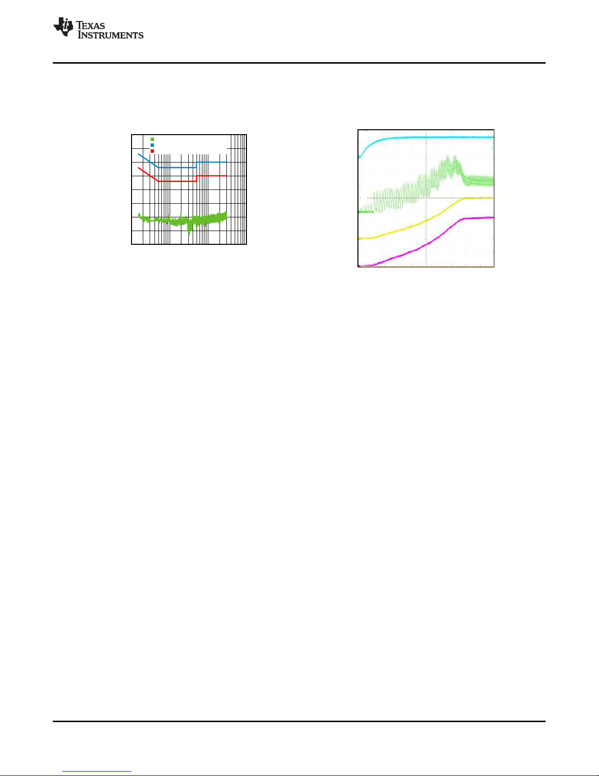
STARTUP BEHAVIOR AND SOFTSTART
The LMZ10500 features a current limit based soft start circuit in order to prevent large in-rush current and output
overshoot as V
final operating value as the output voltage ramps during startup. The maximum allowed current in the inductor is
stepped up in a staircase profile for a fixed number of switching periods in each step. Additionally, the switching
frequency in the first step is set at 450kHz and is then increased for each of the following steps until it reaches
2MHz at the final step of current limiting. This current limiting behavior is illustrated in Figure 35 and allows for a
smooth V
OUT
is ramping up. This is achieved by gradually increasing the PFET current limit threshold to the
OUT
ramp up.
Figure 35. Startup behavior of current limit based softstart.
The soft start rate is also limited by the V
down device before startup occurs. This is done to deplete any residual charge on the V
allow the V
voltage to ramp up from 0V when the part is started. The events that cause V
CON
ramp up rate. The V
CON
pin is discharged internally through a pull
CON
filter capacitor and
CON
discharge are
CON
thermal shutdown, UVLO, EN low, or output short circuit detection. The minimum recommended capacitance on
V
is 220pF and the maximum is 1nF. The duration of startup current limiting sequence takes approximately
CON
75µs. After the sequence is completed, the feedback voltage is monitored for output short circuit events.
OUTPUT SHORT CIRCUIT PROTECTION
In addition to cycle by cycle current limit, the LMZ10500 features a second level of short circuit protection. If the
load pulls the output voltage down and the feedback voltage falls to 0.375V, the output short circuit protection will
engage. In this mode the internal PFET switch is turned OFF after the current limit comparator trips and the
beginning of the next cycle is inhibited for approximately 230µs. This forces the inductor current to ramp down
and limits excessive current draw from the input supply when the output of the regulator is shorted. The
synchronous rectifier is always OFF in this mode. After 230µs of non-switching a new startup sequence is
initiated. During this new startup sequence the current limit is gradually stepped up to the nominal value as
illustrated in the STARTUP BEHAVIOR AND SOFTSTART section. After the startup sequence is completed
again, the feedback voltage is monitored for output short circuit. If the short circuit is still persistent after the new
startup sequence, switching will be stopped again and there will be another 230µs off period. A persistent output
short condition results in a hiccup behavior where the LMZ10500 goes through the normal startup sequence,
then detects the output short at the end of startup, terminates switching for 230µs, and repeats this cycle until the
output short is released. This behavior is illustrated in Figure 36.
14 Submit Documentation Feedback Copyright © 2011–2013, Texas Instruments Incorporated
Product Folder Links: LMZ10500
Page 15

1V/Div
20 MHz BW
5 µs/Div
SWITCH NODE
INPUT VOLTAGE
1V/Div
100 µs/Div
1V/Div
1V/Div
0.3A/Div
50 mA/Div
VCON
IL
IIN
VOUT
LMZ10500
www.ti.com
SNVS723C –OCTOBER 2011–REVISED MARCH 2013
Figure 36. Hiccup behavior with persistent output short circuit.
Since the output current is limited during normal startup by the softstart function, the current charging the output
capacitor is also limited. This results in a smooth V
large output capacitance or V
capacitance under normal conditions can prevent the output voltage from
CON
ramp up to nominal voltage. However, using excessively
OUT
reaching 0.375V at the end of the startup sequence. In such cases the module will maintain the described above
hiccup mode and the output voltage will not ramp up to final value. To cause this condition, one would have to
use unnecessarily large output capacitance for 650mA load applications. See the INPUT AND OUTPUT
CAPACITOR SELECTION section for guidance on maximum capacitances for different output voltage settings.
HIGH DUTY CYCLE OPERATION
The LMZ10500 features a transition mode designed to extend the output regulation range to the minimum
possible input voltage. As the input voltage decreases closer and closer to V
smaller and smaller and the duty cycle eventually needs to reach 100% to support the output voltage. The input
voltage at which the duty cycle reaches 100% is the edge of regulation. When the LMZ10500 input voltage is
lowered, such that the off-time of the PFET reduces to less than 35ns, the LMZ10500 doubles the switching
period to extend the off-time for that VINand maintain regulation. If VINis lowered even more, the off-time of the
PFET will reach the 35ns mark again. The LMZ10500 will then reduce the frequency again, achieving less than
100% duty cycle operation and maintaining regulation. As VINis lowered even more, the LMZ10500 will continue
to scale down the frequency, aiming to maintain at least 35ns off time. Eventually, as the input voltage decreases
further, 100% duty cycle is reached. This behavior of extending the VINregulation range is illustrated in the
following plot.
, the off-time of the PFET gets
OUT
Figure 37. High duty cycle operation and switching frequency reduction.
Copyright © 2011–2013, Texas Instruments Incorporated Submit Documentation Feedback 15
Product Folder Links: LMZ10500
Page 16

10 PF
FB
FB
PGND
SGND
EN
10 PF
R
T
R
B
C
VC
V
CON
V
IN
V
REF
V
OUT
C
IN
C
OUT
LMZ10500
SNVS723C –OCTOBER 2011–REVISED MARCH 2013
www.ti.com
THERMAL OVERLOAD PROTECTION
The junction temperature of the LMZ10500 should not be allowed to exceed its maximum operating rating of
125°C. Thermal protection is implemented by an internal thermal shutdown circuit which activates at 150°C (typ).
When this temperature is reached, the device enters a low power standby state. In this state switching remains
off causing the output voltage to fall. Also, the V
temperature falls back below 130 °C (typ) normal startup occurs and V
capacitor is discharged to SGND. When the junction
CON
rises smoothly from 0V. Applications
OUT
requiring maximum output current may require derating at elevated ambient temperature. See the Typical
Performance Characteristics section for thermal derating plots for various output voltages.
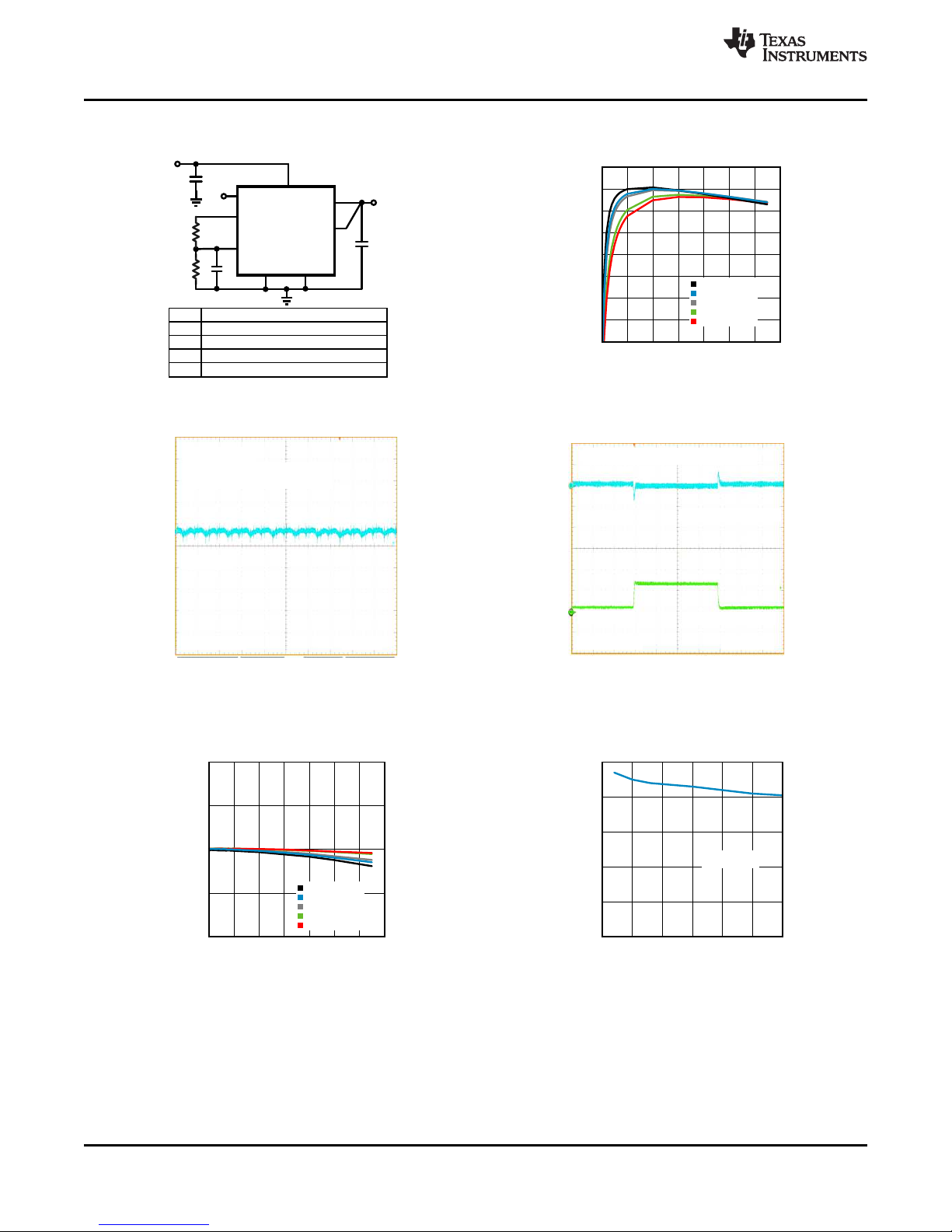
Application Information
Figure 38. Typical Application Circuit
SETTING THE OUTPUT VOLTAGE
The LMZ10500 provides a fixed 2.35V V
formed by RTand RBsets the V
following relationship:
V
= GAIN x V
OUT
CON
where
• GAIN is 2.5V/V from V
This equation is valid for output voltages between 0.6V and 3.6V and corresponds to V
0.24V and 1.44V, respectively.
RTand RBSelection for Fixed V
The parameters affecting the output voltage setting are the RT, RB, and the product of the V
The V
voltage is typically 2.35V. Since V
REF
V
= V
CON
x RB/ (RB+ RT) (2)
REF
After substitution,
V
= V
OUT
RT= ( GAIN x V
The ideal product of GAIN x V
x GAIN x RB/ (RB+ RT) (3)
REF
/ V
OUT
– 1 ) x R
REF
REF
Choose RTto be between 80kΩ and 300kΩ. Then, RBcan be calculated using Equation 5 below.
RB= ( V
/ (5.875V – V
OUT
OUT
) ) x R
Note that the resistance of RTshould be ≥ 80kΩ. This ensures that the V
exceeded and the reference voltage is maintained. The current loading on V
µA.
16 Submit Documentation Feedback Copyright © 2011–2013, Texas Instruments Incorporated
voltage output. As shown in Figure 38 above, a resistive divider
REF
pin voltage level. The V
CON
to VFB. (1)
CON
OUT
is derived from V
CON
B
voltage tracks V
OUT
via RTand RB,
REF
and is governed by the
CON
voltage between
CON
voltage x GAIN.
REF
= 5.875V.
T
output current loading is not
REF
should not be greater than 30
REF
Product Folder Links: LMZ10500
(4)
(5)
Page 17

LMZ10500
www.ti.com
SNVS723C –OCTOBER 2011–REVISED MARCH 2013
OUTPUT VOLTAGE ACCURACY OPTIMIZATION
Each nano module is optimized to achieve high V
voltage is a function of the V
V
. Therefore, as shown in Equation 3, the accuracy of the output voltage is a function of the V
REF
voltage and the gain from V
CON
product as well as the tolerance of the RTand RBresistors. The typical V
Each nano module's V
possible, achieving high V
voltage is trimmed so that this product is as close to the ideal 5.875V value as
REF
accuracy. See the Electrical Specifications for the V
OUT
accuracy. Equation 1 shows that, by design, the output
OUT
to VFB. The voltage at V
CON
x GAIN product by design is 5.875V.
REF
is derived from
CON
REF
x GAIN product tolerance
REF
x GAIN
limits.
DYNAMIC OUTPUT VOLTAGE SCALING
The V
output voltage V
in series with the V
pin on the LMZ10500 can be driven externally by a DAC to scale the output voltage dynamically. The
CON
= 2.5V/V x V
OUT
CON
. When driving V
CON
with a source different than V
CON
pin. Current limiting the external V
place a 1.5kΩ resistor
helps to protect this pin and allows the V
CON
REF
CON
capacitor to be fully discharged to 0V after fault conditions.
INTEGRATED INDUCTOR
The LMZ10500 uses a Low Temperature Co-fired Ceramic (LTCC) type 2.6 µH inductor with over 1.2A DC
current rating and soft saturation profile for up to 2A. This inductor allows for the 1.425mm maximum package
height providing an easy to use, compact solution with reduced EMI.
INPUT AND OUTPUT CAPACITOR SELECTION
The LMZ10500 is designed for use with low ESR multi-layer ceramic capacitors (MLCC) for its input and output
filters. Using a 10 µF 0603 or 0805 with 6.3V or 10V rating ceramic input capacitor typically provides sufficient
VINbypass. Use of multiple 4.7 µF or 2.2µF capacitors can also be considered. Ceramic capacitors with X5R and
X7R temperature characteristics are recommended for both input and output filters. These provide an optimal
balance between small size, cost, reliability, and performance for space sensitive applications.
The DC voltage bias characteristics of the capacitors must be considered when selecting the DC voltage rating
and case size of these components. The effective capacitance of an MLCC is typically reduced by the DC
voltage bias applied across its terminals. For example, a typical 0805 case size X5R 6.3V 10 µF ceramic
capacitor may only have 4.8 µF left in it when a 5.0V DC bias is applied. Similarly, a typical 0603 case size X5R
6.3V 10 µF ceramic capacitor may only have 2.4 µF at the same 5.0V DC. Smaller case size capacitors may
have even larger percentage drop in value with DC bias.
The optimum output capacitance value is application dependent. Too small output capacitance can lead to
instability due to lower loop phase margin. On the other hand, if the output capacitor is too large, it may prevent
the output voltage from reaching the 0.375V required voltage level at the end of the startup sequence. In such
cases, the output short circuit protection can be engaged and the nano module will enter a hiccup mode as
described in the OUTPUT SHORT CIRCUIT PROTECTION section. Table 1 sets the minimum output
capacitance for stability and maximum output capacitance for proper startup for various output voltage settings.
Note that the maximum C
recommended value of 1nF and the RTresistor value is less than 300kΩ. Lower V
the maximum C
range. There is no great performance benefit in using excessive C
OUT
value in Table 1 assumes that the filter capacitance on V
OUT
is the maximum
CON
capacitance can extend
CON
values.
OUT
Output Voltage Minimum Suggested Maximum
C
0.6V 4.7µF 10µF 33µF
1.0V 3.3µF 10µF 33µF
1.2V 3.3µF 10µF 33µF
1.8V 3.3µF 10µF 47µF
2.5V 3.3µF 10µF 68µF
3.3V 3.3µF 10µF 68µF
Copyright © 2011–2013, Texas Instruments Incorporated Submit Documentation Feedback 17
Table 1. Output Capacitance Range
OUT
Product Folder Links: LMZ10500
C
OUT
C
OUT
Page 18

LMZ10500
SNVS723C –OCTOBER 2011–REVISED MARCH 2013
www.ti.com
Use of multiple 4.7 µF or 2.2µF output capacitors can be considered for reduced effective ESR and smaller
output voltage ripple. In addition to the main output capacitor, small 0.1µF – 0.01µF parallel capacitors can be
used to reduce high frequency noise.
PACKAGE CONSIDERATIONS
The nano module package includes an LTCC inductor on the bottom and a micro SMD die mounted on top. The
die has exposed edges and can be sensitive to ambient light. For applications with direct high intensity ambient
red, infrared, LED, or natural light it is recommended to have the device shielded from the light source to avoid
abnormal behavior.
Since the die is exposed on top of the package, care should be taken when picking and placing the module on
the board.
Use the following recommendations when utilizing machine placement:
• Use 1.06mm (42mil) or smaller nozzle size so that the nozzle head does not touch the outer area of the
exposed die.
• Use a soft tip pick and place head.
• Add 0.05mm to the component thickness so that the device will be released 0.05mm (2mil) into the solder
paste without putting pressure or splashing the solder paste.
• Slow the pick arm when picking the part from the tape and reel carrier and when depositing the IC on the
board.
• If the machine releases the component by force, use minimum force or no more than 3 Newtons.
• For PCBs with surface mount components on both sides, it is suggested to put the LMZ10500 on the top
side. In case the application requires bottom side placement, a reflow fixture may be required to protect the
module during the second reflow.
For manual placement:
• Use a vacuum pick up hand tool with soft tip head.
• If vacuum pick up tool is not available, use non-metal tweezers and hold the part by the inductor body side
terminals rather than the micro SMD die on top.
• Use minimal force when picking and placing the module on the board.
• In case a heat gun is required for rework, make sure that the heat source is pointing at the interface between
the inductor and the PCB. Do not apply heat gun directly on top of the component since it may affect the
solder joint between the micro SMD and the inductor. Using hot air station provides better temperature control
and better controlled air flow than a heat gun.
• Go to the video section at www.ti.com/product/lmz10500 for a quick video on how to solder rework the
LMZ10500.
18 Submit Documentation Feedback Copyright © 2011–2013, Texas Instruments Incorporated
Product Folder Links: LMZ10500
Page 19

INPUT
CAPACITOR
OUTPUT
CAPACITOR
FEEDBACK
TRACE
VIN
VOUT
VCON
CAPACITOR
VREF
VIN
PGND
VOUT
SGND
FB
SGND CONNECTION TO
QUIET PGND PLANE
VCON
EN
RT
RESISTOR
RB
RESISTOR
HIGH di/dt LOOP
KEEP IT SMALL
PGND
LMZ10500
www.ti.com
Board Layout Considerations
SNVS723C –OCTOBER 2011–REVISED MARCH 2013
Figure 39. Example Top Layer Board Layout
The board layout of any DC-DC switching converter is critical for the optimal performance of the design. Bad
PCB layout design can disrupt the operation of an otherwise good schematic design. Even if the regulator still
converts the voltage properly, the board layout can mean the difference between passing or failing EMI
regulations. In a Buck converter, the most critical board layout path is between the input capacitor ground
terminal and the synchronous rectifier ground. The loop formed by the input capacitor and the power FETs is a
path for the high di/dt switching current during each switching period. This loop should always be kept as short
as possible when laying out a board for any Buck converter.
The LMZ10500 integrates the inductor and simplifies the DC-DC converter board layout. Refer to the example
layout in Figure 39. There are a few basic requirements to achieve a good LMZ10500 layout.
1. Place the input capacitor CINas close as possible to the VINand PGND terminals. VIN(pin 7) and PGND
(pin 6) on the LMZ10500 are next to each other which makes the input capacitor placement simple.
2. Place the V
SGND terminals.The CVCcapacitor (not RB) should be the component closer to the V
Figure 39. This allows for better bypass of the control voltage set at V
3. Run the feedback trace (from V
4. Connect SGND to a quiet GND plane.
5. Provide enough PCB area for proper heatsinking. Refer to the Electrical Characteristics table for example
θ
values for different board areas. Also, refer to AN-2020 for additional thermal design hints.
JA
Refer to the evaluation board application note AN-2166 for a complete board layout example.
CON
filter capacitor CVCand the RBRTresistive divider as close as possible to the V
to FB) away from noise sources.
OUT
CON
pin, as shown in
CON
.
CON
and
Copyright © 2011–2013, Texas Instruments Incorporated Submit Documentation Feedback 19
Product Folder Links: LMZ10500
Page 20

LMZ10500
SNVS723C –OCTOBER 2011–REVISED MARCH 2013
www.ti.com
REVISION HISTORY
Changes from Revision B (March 2013) to Revision C Page
• Changed layout of National Data Sheet to TI format .......................................................................................................... 19
20 Submit Documentation Feedback Copyright © 2011–2013, Texas Instruments Incorporated
Product Folder Links: LMZ10500
Page 21

PACKAGE OPTION ADDENDUM
www.ti.com
31-May-2013
Addendum-Page 1
PACKAGING INFORMATION
Orderable Device Status
(1)
Package Type Package
Drawing
Pins Package
Qty
Eco Plan
(2)
Lead/Ball Finish MSL Peak Temp
(3)
Op Temp (°C) Device Marking
(4/5)
Samples
LMZ10500SH/NOPB ACTIVE POS NQB 8 1000 Pb-Free (RoHS
Exempt)
Call TI Level-3-260C-168 HR -40 to 85
LMZ10500SHE/NOPB ACTIVE POS NQB 8 250 Pb-Free (RoHS
Exempt)
Call TI Level-3-260C-168 HR -40 to 85
LMZ10500SHX/NOPB ACTIVE POS NQB 8 3000 Pb-Free (RoHS
Exempt)
Call TI Level-3-260C-168 HR -40 to 85
(1)
The marketing status values are defined as follows:
ACTIVE: Product device recommended for new designs.
LIFEBUY: TI has announced that the device will be discontinued, and a lifetime-buy period is in effect.
NRND: Not recommended for new designs. Device is in production to support existing customers, but TI does not recommend using this part in a new design.
PREVIEW: Device has been announced but is not in production. Samples may or may not be available.
OBSOLETE: TI has discontinued the production of the device.
(2)
Eco Plan - The planned eco-friendly classification: Pb-Free (RoHS), Pb-Free (RoHS Exempt), or Green (RoHS & no Sb/Br) - please check http://www.ti.com/productcontent for the latest availability
information and additional product content details.
TBD: The Pb-Free/Green conversion plan has not been defined.
Pb-Free (RoHS): TI's terms "Lead-Free" or "Pb-Free" mean semiconductor products that are compatible with the current RoHS requirements for all 6 substances, including the requirement that
lead not exceed 0.1% by weight in homogeneous materials. Where designed to be soldered at high temperatures, TI Pb-Free products are suitable for use in specified lead-free processes.
Pb-Free (RoHS Exempt): This component has a RoHS exemption for either 1) lead-based flip-chip solder bumps used between the die and package, or 2) lead-based die adhesive used between
the die and leadframe. The component is otherwise considered Pb-Free (RoHS compatible) as defined above.
Green (RoHS & no Sb/Br): TI defines "Green" to mean Pb-Free (RoHS compatible), and free of Bromine (Br) and Antimony (Sb) based flame retardants (Br or Sb do not exceed 0.1% by weight
in homogeneous material)
(3)
MSL, Peak Temp. -- The Moisture Sensitivity Level rating according to the JEDEC industry standard classifications, and peak solder temperature.
(4)
There may be additional marking, which relates to the logo, the lot trace code information, or the environmental category on the device.
(5)
Multiple Device Markings will be inside parentheses. Only one Device Marking contained in parentheses and separated by a "~" will appear on a device. If a line is indented then it is a continuation
of the previous line and the two combined represent the entire Device Marking for that device.
Important Information and Disclaimer:The information provided on this page represents TI's knowledge and belief as of the date that it is provided. TI bases its knowledge and belief on information
provided by third parties, and makes no representation or warranty as to the accuracy of such information. Efforts are underway to better integrate information from third parties. TI has taken and
continues to take reasonable steps to provide representative and accurate information but may not have conducted destructive testing or chemical analysis on incoming materials and chemicals.
TI and TI suppliers consider certain information to be proprietary, and thus CAS numbers and other limited information may not be available for release.
Page 22

PACKAGE OPTION ADDENDUM
www.ti.com
31-May-2013
Addendum-Page 2
In no event shall TI's liability arising out of such information exceed the total purchase price of the TI part(s) at issue in this document sold by TI to Customer on an annual basis.
Page 23

PACKAGE MATERIALS INFORMATION
www.ti.com 26-Mar-2013
TAPE AND REEL INFORMATION
*All dimensions are nominal
Device Package
Type
LMZ10500SH/NOPB POS NQB 8 1000 178.0 12.4 3.8 3.8 2.2 8.0 12.0 Q1
LMZ10500SHE/NOPB POS NQB 8 250 178.0 12.4 3.8 3.8 2.2 8.0 12.0 Q1
LMZ10500SHX/NOPB POS NQB 8 3000 330.0 12.4 3.8 3.8 2.2 8.0 12.0 Q1
Package
Drawing
Pins SPQ Reel
Diameter
(mm)
Reel
Width
W1 (mm)
A0
(mm)B0(mm)K0(mm)P1(mm)W(mm)
Pin1
Quadrant
Pack Materials-Page 1
Page 24

PACKAGE MATERIALS INFORMATION
www.ti.com 26-Mar-2013
*All dimensions are nominal
Device Package Type Package Drawing Pins SPQ Length (mm) Width (mm) Height (mm)
LMZ10500SH/NOPB POS NQB 8 1000 210.0 185.0 35.0
LMZ10500SHE/NOPB POS NQB 8 250 210.0 185.0 35.0
LMZ10500SHX/NOPB POS NQB 8 3000 367.0 367.0 35.0
Pack Materials-Page 2
Page 25

Page 26

Page 27

Page 28

IMPORTANT NOTICE
Texas Instruments Incorporated and its subsidiaries (TI) reserve the right to make corrections, enhancements, improvements and other
changes to its semiconductor products and services per JESD46, latest issue, and to discontinue any product or service per JESD48, latest
issue. Buyers should obtain the latest relevant information before placing orders and should verify that such information is current and
complete. All semiconductor products (also referred to herein as “components”) are sold subject to TI’s terms and conditions of sale
supplied at the time of order acknowledgment.
TI warrants performance of its components to the specifications applicable at the time of sale, in accordance with the warranty in TI’s terms
and conditions of sale of semiconductor products. Testing and other quality control techniques are used to the extent TI deems necessary
to support this warranty. Except where mandated by applicable law, testing of all parameters of each component is not necessarily
performed.
TI assumes no liability for applications assistance or the design of Buyers’ products. Buyers are responsible for their products and
applications using TI components. To minimize the risks associated with Buyers’ products and applications, Buyers should provide
adequate design and operating safeguards.
TI does not warrant or represent that any license, either express or implied, is granted under any patent right, copyright, mask work right, or
other intellectual property right relating to any combination, machine, or process in which TI components or services are used. Information
published by TI regarding third-party products or services does not constitute a license to use such products or services or a warranty or
endorsement thereof. Use of such information may require a license from a third party under the patents or other intellectual property of the
third party, or a license from TI under the patents or other intellectual property of TI.
Reproduction of significant portions of TI information in TI data books or data sheets is permissible only if reproduction is without alteration
and is accompanied by all associated warranties, conditions, limitations, and notices. TI is not responsible or liable for such altered
documentation. Information of third parties may be subject to additional restrictions.
Resale of TI components or services with statements different from or beyond the parameters stated by TI for that component or service
voids all express and any implied warranties for the associated TI component or service and is an unfair and deceptive business practice.
TI is not responsible or liable for any such statements.
Buyer acknowledges and agrees that it is solely responsible for compliance with all legal, regulatory and safety-related requirements
concerning its products, and any use of TI components in its applications, notwithstanding any applications-related information or support
that may be provided by TI. Buyer represents and agrees that it has all the necessary expertise to create and implement safeguards which
anticipate dangerous consequences of failures, monitor failures and their consequences, lessen the likelihood of failures that might cause
harm and take appropriate remedial actions. Buyer will fully indemnify TI and its representatives against any damages arising out of the use
of any TI components in safety-critical applications.
In some cases, TI components may be promoted specifically to facilitate safety-related applications. With such components, TI’s goal is to
help enable customers to design and create their own end-product solutions that meet applicable functional safety standards and
requirements. Nonetheless, such components are subject to these terms.
No TI components are authorized for use in FDA Class III (or similar life-critical medical equipment) unless authorized officers of the parties
have executed a special agreement specifically governing such use.
Only those TI components which TI has specifically designated as military grade or “enhanced plastic” are designed and intended for use in
military/aerospace applications or environments. Buyer acknowledges and agrees that any military or aerospace use of TI components
which have not been so designated is solely at the Buyer's risk, and that Buyer is solely responsible for compliance with all legal and
regulatory requirements in connection with such use.
TI has specifically designated certain components as meeting ISO/TS16949 requirements, mainly for automotive use. In any case of use of
non-designated products, TI will not be responsible for any failure to meet ISO/TS16949.
Products Applications
Audio www.ti.com/audio Automotive and Transportation www.ti.com/automotive
Amplifiers amplifier.ti.com Communications and Telecom www.ti.com/communications
Data Converters dataconverter.ti.com Computers and Peripherals www.ti.com/computers
DLP® Products www.dlp.com Consumer Electronics www.ti.com/consumer-apps
DSP dsp.ti.com Energy and Lighting www.ti.com/energy
Clocks and Timers www.ti.com/clocks Industrial www.ti.com/industrial
Interface interface.ti.com Medical www.ti.com/medical
Logic logic.ti.com Security www.ti.com/security
Power Mgmt power.ti.com Space, Avionics and Defense www.ti.com/space-avionics-defense
Microcontrollers microcontroller.ti.com Video and Imaging www.ti.com/video
RFID www.ti-rfid.com
OMAP Applications Processors www.ti.com/omap TI E2E Community e2e.ti.com
Wireless Connectivity www.ti.com/wirelessconnectivity
Mailing Address: Texas Instruments, Post Office Box 655303, Dallas, Texas 75265
Copyright © 2013, Texas Instruments Incorporated
 Loading...