

Page 1
LMX9838DONGLE Hardware User Guide
LMX9838DONGLE Hardware User Guide
February 2007
Revision 0.3
1.0 Scope
National Semiconductor LMX9838 Bluetooth™ serial dongle reference design ki t is a plug and play serial a dap ter for
serial cable replacement applications and more. It is able
to support more profiles than just the Serial Port Profile
(including audio support with external codec boards). By
using the enclosed Simply Blue Commander software, it
allows user to develop their own SW applications easily
given the built in interpreter for HEX commands. SBSmart
is a higher level application tool that provides buttons with
the built in commands to easily set up or demonstrate different profile support using the Simply Blue SPP package.
2.0 General Description
2.1 REFERENCE DESIGN KIT CONTENTS
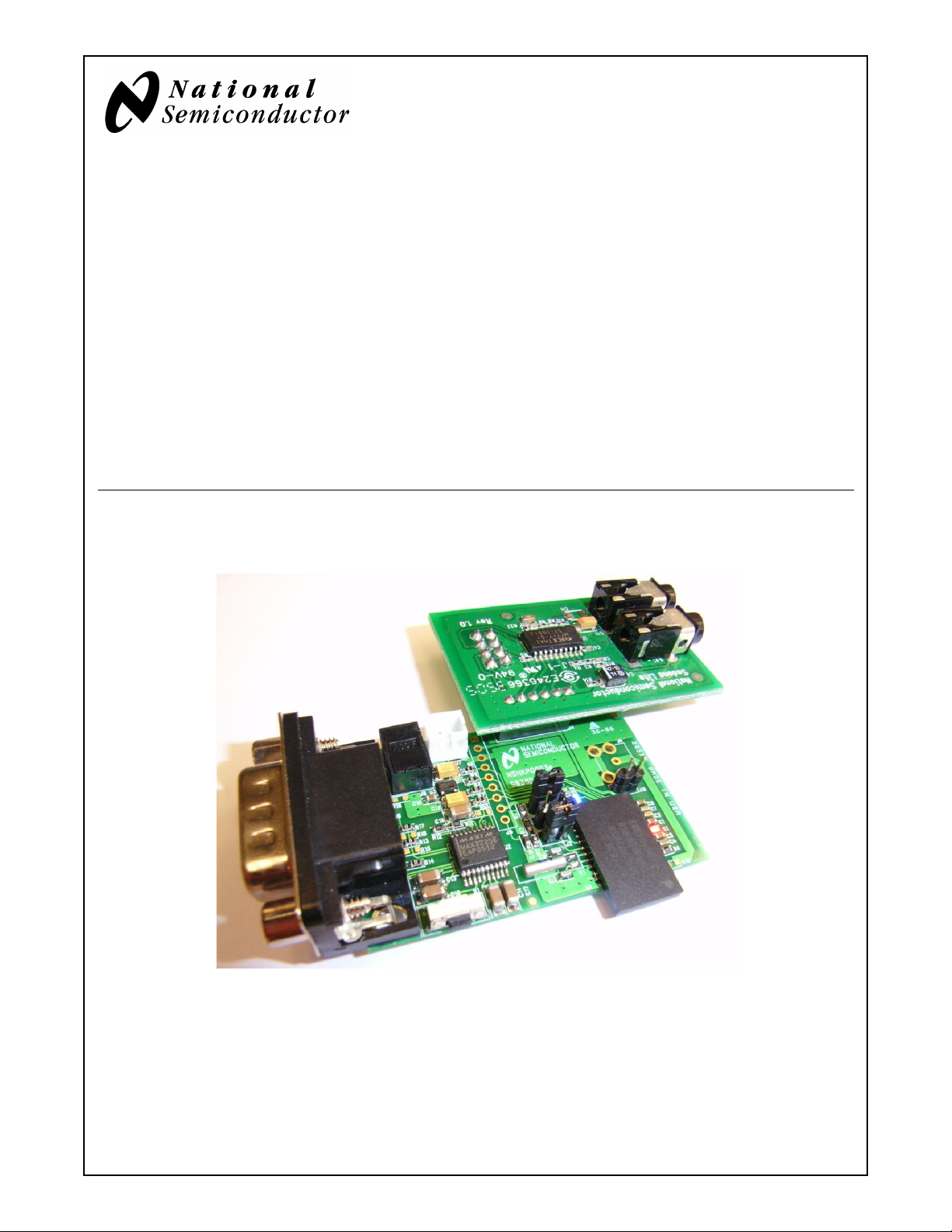
■ LMX9838 Bluetooth serial adapter reference board
■ USB Dongle and application software stack
■ Null modem cabl e
■ Sedona Lite board (Audio CODEC Board)
■ 110V to 240V AC to 5V DC power adapter and pigtail
■ CDROM with design documents and Simply Blue soft-
ware Application tools.
2.2 LMX9838 BLUETOOTH SERIAL
ADAPTER REFERENCE BOARD
Figure 1. Reference Board and Sedona Lite Board
Bluetooth is a trademark of Bluetooth SIG, Inc. and is used under license by National Semiconductor.
© 2006 National Semiconductor Corporation www.national.com
Page 2
3.0 Qualification
■ FCC certified:
— FCC ID: ED9LMX9838
■ FCC compliance (see Section 13.0): The device com-
plies with Part 15 of FCC Rules. Operation is subject to
the following two conditions:
— This device may not ca use harmful interference
— This device must accept any interference received,
including interference that may cause undesired
operation
■ IC certified:
— IC: 1520A-LMX9838
■ Bluetooth SIG QD ID: B012394
4.0 Requirement and Setup
4.1 BASIC REQUIREMENT
LMX9838DONGLE Hardware User Guide
■ X86 PC with serial port.
■ One of the following operating system is required.
— Windows 2000
—Windows XP
4.2 APPLICATION SOFTWARE
4.2.1 Simply Blue Commander
Applicatio n com man d or ien ted t ool to ge ner ate comm ands
and watch events in the Simply Blue Command interface
window. Reference the Simply Blue Commander User
Guide document for details.
4.2.2 SBSmart
Easy to use Windows based tool to demonstrate additional
profile support of the Simply Blue functionality. Reference
the SBSmart User Guide for additional details.
4.2.3 Patch Programming
LMX9838 allows for patch programming for firmware
update if necessary. Reference the LMX9838 SW User
Guide document for details. This can also be done with the
Simply Blue Commander and SBSmart tools.
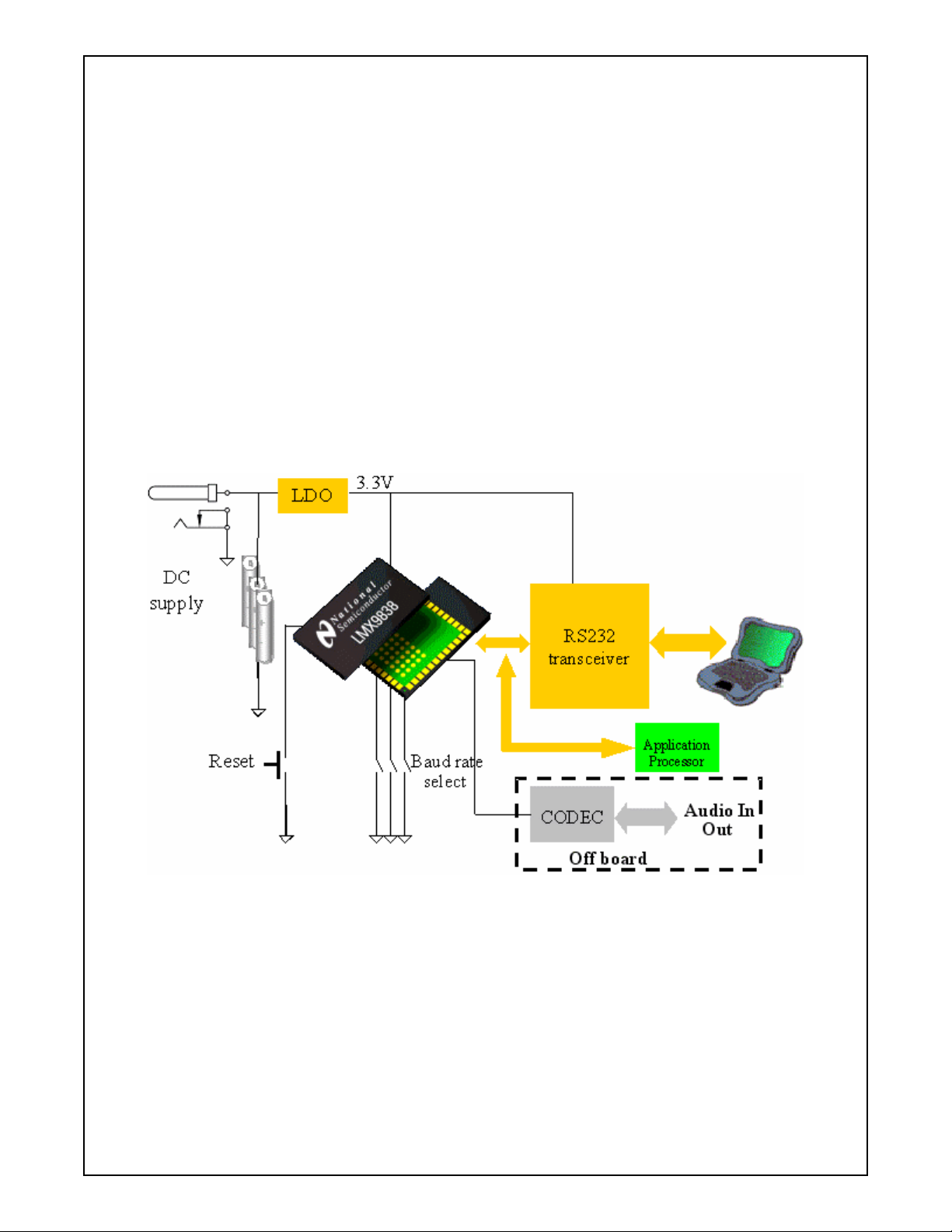
Figure 2. System Block Diagram
5.0 Functional Description
5.1 POWER SUPPLY
■ DC Power Jack (6V max)
■ Battery Holder (6V max)
5.2 MAIN SYSTEM
■ Reset button for manual Reset
■ Jumper option for Baud rate selection
www.national.com 2
5.3 UART INTERFACE
DB9 connector for RS232 standard PC interface using Onboard level shifter IC for handling LMX9838 module’s 3.3V
UART interface.
5.4 ADVANCE AUDIO INTERFACE
■ Support Audio applications
■ PCM codec interface (support linear and A-law)
■ PCM Master or Slave operation (SW configurable)
■ Direct connection to Sedona Lite Board (A-law only)
Page 3
LMX9838DONGLE Hardware User Guide
6.0 Design Consideration
6.1 POWER MANAGEMENT
■ 3.3V output single LDO is used to provide power for
RS232 interface chi p and Digital porti on of the LMX983 8.
7.0 Layout Consideration
The LMX9838 reference design is split into 2 sections, one
section is RS232 transceiver circuit for PC connection,
another section is LMX9838 main circuit for Host processor. (Fig ure 3)
7.1 PCB REQUIREMENT
■ 2 layers PCB required
■ 1 mm overall thickness
7.2 LAYERS CLASSIFICATION
■ Top layer is the components and main signals layer
■ Bottom layer is interface signals and ground plane
■ RF circuit requirement
■ Large ground plane with ground via’s is must for good
RF performance
8.0 AUDIO CODEC Board
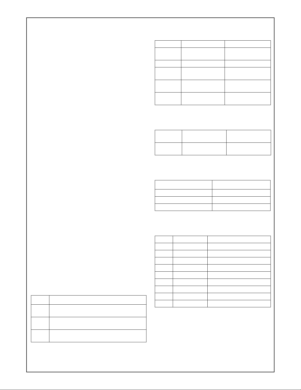
Table 2 Connectors Summary
Connector Description Details
J7 Battery Connector
2mm pitch
J6 DC jack Same as above
J8 DP9 serial connec-
tor (male)
J5 External processor
interface
J4 Advance Audio
interface
Table 3 Jumper and Test Point Summary
Jumper /
Test Point
J1, J2 and J3Clock & UART set-
Description Details
ting jumper
Maximum input voltage is 6V
See Table 5
See Table 6
See Table 7
See Table 8
Table 4 Switch and LEDs
Switch/LED Description
S1 Reset button
D1 Operation Status
D2 Data Traffic (TX/RX)
Sedona Lite Board c on t ai ns an audio codec a nd two phone
jacks. This board can be used in conjuction with
LMX9838DONGLE to realize the audio (SCO) transmission and reception capabilities. (See Table 9)
9.0 Board components and Pin Assignments
A summary of t he configuration and se lection jumpers is
provided in the tables that follow. Reference both the schematic and PCB layout (included on the CD in the kit)
Table 1 Major Components List
Device Description
National LMX9838 Serial Port Module - Refer-
U1
ence the device datasheet.
National LP3985 Low-Dropout Voltage Regula-
U3
tor
Maxim MAX3225 1 Mbps High Speed UART
U2
Driver
Table 5 J8 DP9 (male) Pin Assignments
Pin # Signal name Description
1 NC No connection
2 RxD Receive Data (inp ut)
3 TxD Transmit Data (output)
4 NC No connection
5 GND Ground
6 NC No connection
7 RTS Ready to send (output)
8 CTS Clear to send (input)
9 NC No connection
3 www.national.com
Page 4

Table 6 J5 External Processor Interface
Table 8 UART interface setting
Pin # Signal name Description
1 POWER_D# ON/OFF control of LMX9838
2 VCC LDO output (3.3V)
3 GND Ground
4 TXD Transmit Data (output)
5 CTS# Clear to send (input)
6 RXD Receive Data (input)
7 RTS# Ready to send (output)
8 VCC_CORE
_IN
9 RESET# Reset (input)
LMX9838DONGLE Hardware User Guide
Table 7 J4
Pin # Signal name Description
1VCC
2SCLK
3STD
4SFS
5SRD
6GND
1.8V voltage regulator input/output
Advance Audio Interface
LDO output (3.3V)
Advanced Audio Interface Clock
Advanced Audio Interface
Transmit Data
Advanced Audio Interface Frame
Synchronization
Advanced Audio Interface
Receive Data
Ground
J2 J3 J1 UA RT baud rate
Short Short Short 921600bps
Short Open Short 115200bps(default)
Open Short Short 9600bps
Open Open Short NVS (Default 9600bps)
Table 9 J4 (Audio CODEC Board)
Pin # Signal name Description
1Vcc
2SCLK
3STD
4SFS
5SRD
6GND
Table 10 Audio C onnection
P17 For PC Microphone
P15 For PC Headphone
3.3V Input
PCM Clock
PCM Input Data
PCM Frame Synchronization
PCM Output Data
Ground
Figure 3. Top view of Reference board
www.national.com 4
Page 5

10.0 Bill of materials (Reference Board)
Item Name Description Vendor Part Number
C5,C6 Capacitor 22p 0603 C0G 50V MuRata GRM39C0G220J50
C1,C3,C8,
C10
C2,C4,C7 Capacitor 2u2F 0603 Y5V 10V MuRata GRM39Y5V225Z10
C9 Capacitor 100p 0603 C0G 50V MuRata GRM39C0G101J50
C11,C12 TANT CAP 1uF 16V SIZE A Any
C13,C14,C15,
C16,C17
C19 Capacitor 1uF 0603 Y5V 10V MuRata GRM39Y5V105Z10
J7 Battery hol der (2mm pitc h) Any
S1 TACK SWITCH TS-1135HS RAINBOW
Y1 Tuning fork crystal 32.768KHz Any
J6 DC POWER JACK Morning star limited DC-015
D1 Red Color LED 0603 Size Any
D2 Blue Color LED 0603 Size Any
J8 DB9 (male) serial connector Any
J4 2mm Socket (6 poles) Any
U1 Bluetooth SPP Micro Module National Semiconductor LMX9838SM
U3 Low Dropout Regulator National Semiconductor LP3985IM5X-3.3
U2 High Speed RS232 Transceivers Maxim MAX3225EEAP+
R1,R2,R3 Resistor 0603 Size, 1K Any
R11,R12 Resistor 0603 Size, 10K Any
R6,R7,R8,R9,
R13,R14,R17
R4,R5 Resistor 0603 Size, 330R Any
J3,J10 2mm header Any
J1,J2 2mm header (with jumper) Any
Capacitor 100n 0603 Y5V 50V MuRata GRM39Y5V104Z50
Capacitor 1uF 1206 X7R 25V MuRata GRM42-6X7R105K25
Resistor 0603 Size, 0R Any
LMX9838DONGLE Hardware User Guide
11.0 Bill of Materials (Sedona Lite Board)
Item Name Description Vendor Part Number
C3,C4,C5,C6 Capacitor 100nF Any Ceramic cap
C6 Capacitor 1uF Any Ceramic cap
C12 TANT CAP 10uF, 10V Any
C40 TANT CAP 47uF, 6.3V Any
C11 Not mount
J1 2mm socket (6 poles) Any
J2 2.54mm sock et (2 x 4 poles) Any
P15 Socket for speaker (mono) Morning Star MSJ-1537
P17 Socket for microphone (mono) Morning Star MSJ-1537
R10 Resistor 0402 Size, 10R Any
R13,R14 Resistor 0402 Size, 1K Any
R5,R22 Resistor 0402 Size, 4.7K Any
5 www.national.com
Page 6

Item Name Description Vendor Part Number
R3 Resistor 0402 Size, 10K Any
R4,R8,R9 Resistor 0402 Size, 47K Any
U2 Single Rail Codec OKI MSM7717-01MS-K
12.0 References
■ LMX9838 Bluetooth Serial Port Module data sheet
LMX9838DONGLE Hardware User Guide
■ LMX9838 Blu etooth Serial Port Module - Sof tware Users
Guide
■ SBSmart user guide
Figure 4. Sedona Board
www.national.com 6
Page 7

13.0 Appendix: FCC instructions
13.1 SAFETY INFORMATION FOR RF
EXPOSURE
13.1.1 FCC Radiation Exposure Statement:
This equipment complies with FCC radiation exposure limits set forth for an uncontrolled environment. End users
must follow the specific operating instructions for satisfying
RF exposure complia nc e.
This device is intended only form OEM integrators under
the following conditions:
1. The anten na must be installed su ch that 20c m is main-
tained between the antenna and users;
and
2. The transmitter module may not be co-located with any
other transmitter or antenna.
IMPORTANT NOTE: In the event that these conditions can
not be met (for examp le ce rtain laptop con fig urat ion s or c olocation with another transmitter), then the FCC authorization is no longer considered valid and the FCC ID can not
be used on the final product. In these circumstances, the
OEM integrator will be responsible for re-evaluating the
end product (includ ing th e transmitter) and obtaining a separate FCC authorization.
13.1.2 End Product Labeling
This transmitter module is authorized only for use in
devices where the antenna may be installed such that 20
cm may be maintained between the antenna and users.
The final end product must be labeled in visible area with
the following:
“Contains TX FCC ID: ED9LMX9838”
13.1.3 End Product Manual Information
LMX9838DONGLE Hardware User Guide
rect the interference by one or more of the following measures:
■ Reorient or relocate the receiving antenna.
■ Increase the separation between the equipment and re-
ceiver.
■ Connect the equipment i nto an outlet of a c ircuit different
from that to which the receiver is connected.
■ Consult the dealer or an experienced radio/TV technician for assistance.
Changes or modification not expressly approved by the
party responsible for Compliance could void the user’s
authority to operate the equipment. Connecting of peripherals requires the use of grounded shielded signal cables.
13.2.2 FCC Compliance Information
This device complies with Part 15 of FCC Rules.
Operation is subject to the following two conditions:
1) This device may not cause harmful interference, and
2) This device must accept any interference received,
including interference that may cause undesired operation.
The user manual for end users must include the following
information in a prominent location:
“IMPORTANT NOTE:
To comply with FCC RF exposure compliance require-
ments, the antenna used for this transmitter must be
installed to provide a s eparation distance of a t least 20 cm
from all persons and mus t no t be c o-l oc ated or op erat ing in
conjunction with any other ante nna or transm itte r.”
13.2 RADIO FREQUENCY INTERFERENCE
STATEMENT
13.2.1 INFORMATION TO THE USER
NOTE : This equipm en t h as been tested and fou nd to comply with the limits for a Class B digital device pursuant to
Part 15 of the FCC Rules.
These limits are designed to provide reasonable protection
against harmful Interference in a residential installation
This equipment generates, uses, and can radiate radio frequency energy and, i f Not inst a lled and used in accord ance
with the instructions, may cause harmful Interference to
radio communicati ons . H owe ver, th ere i s n o g uara nte e th at
interference will not occur in a particular Installation. If this
equipment does caus e harm ful int erferenc e to rad io or television reception, which can be determined by turning the
equipment off and on, the user is encouraged to try to cor-
7 www.national.com
Page 8

LMX9838DONGLE Designer Guide
LIFE SUPPORT POLICY
NATIONAL’S PRODUCTS ARE NOT AUTHORIZED FOR USE AS CRITICAL COMPONENTS IN LIFE SUPPORT
DEVICES OR SYSTEMS WITHOUT THE EXPRESS WRITTEN APPROVAL OF THE PRESIDENT AND GENERAL
COUNSEL OF NATIONAL SEMICONDUCTOR CORPORATION. As used herein:
1. Life support devices or systems are devices or systems which,
(a) are intended for surgical implant into the body, or (b) support
or sustain life, and whose failure to perform, when properly used
in accordance with instructions for use provided in the labeling,
can be reasonably expected to result in a significant injury to the
user.
2. A critical component is any component of a life support device
or system whose failure to perform can be reasonably expected
to cause the failure of the life support device or system, or to affect its safety or effectiveness.
BANNED SUBSTANCE COMPLIANCE
National Semiconductor certifies that the products and packing materi als meet the provisions of the Customer Products Stewardship
Specification (CSP-9-111C2) and the Banned Substances and Materials of Interest Specification (CSP-9-111S2) and contain no “Banned
Substances” as defined in CSP-9-111S2.
Leadfree products are RoHS compliant.
National Semiconductor
Corporation
Tel: 1-800-272-9959
Fax: 1-800-737-7018
Email: support@nsc.com
www.national.com
National does not assume any responsibility for use of any circuitry described, no circuit patent licenses are implied and National reserves the right at any time without notice to change said circuitry and specifications.
National Semiconductor
Europe
Fax: +49 (0) 180-530 85 86
Email: europe.support@nsc.com
Deutsch Tel: +49 (0) 69 9508 6208
English Tel: +44 (0) 870 24 0 2171
Francais Tel: +33 (0) 1 41 91 8790
National Semiconductor
Asia Pacific
Customer Response Group
Tel: 65-254-4466
Fax: 65-250-4466
Email: ap.support@nsc.com
National Semiconductor
Japan Ltd.
Tel: 81-3-5639-7560
Fax: 81-3-5639-7507
 Loading...