

Page 1

LAUNCHXL-F28027 C2000 Piccolo LaunchPad
Experimenter Kit
User's Guide
Literature Number: SPRUHH2A
July 2012–Revised January 2014
Page 2
Contents
1 LAUNCHXL-F28027 Overview ............................................................................................... 4
1.1 Overview .................................................................................................................. 4
1.2 Kit Contents .............................................................................................................. 5
1.3 Revisions ................................................................................................................. 5
2 Installation ......................................................................................................................... 5
2.1 Download the Required Software ..................................................................................... 5
2.2 Install the Software ...................................................................................................... 6
2.3 Install the Hardware ..................................................................................................... 6
3 Getting Started with the LAUNCHXL-F28027 ........................................................................... 6
3.1 Getting Started ........................................................................................................... 6
3.2 Demo Application, Internal Temperature Measurement ............................................................ 6
3.3 Program and Debug the Temperature Measurement Demo Application ........................................ 6
4 Hardware Configuration ....................................................................................................... 6
4.1 Power Domain ........................................................................................................... 7
4.2 Serial Connectivity ...................................................................................................... 7
4.3 Boot Mode Selection .................................................................................................... 7
4.4 Connecting a Crystal .................................................................................................... 7
4.5 Connecting a Satellite Board .......................................................................................... 7
4.6 Device Migration Path .................................................................................................. 8
5 LAUNCHXL-F28027 Hardware ............................................................................................... 8
5.1 Device Pin Out ........................................................................................................... 8
5.2 Schematics ............................................................................................................... 9
5.3 PCB Layout ............................................................................................................. 11
5.4 Bill of Materials (BOM) ................................................................................................ 12
6 Suggested Reading ........................................................................................................... 13
7 Frequently Asked Questions (FAQ) ...................................................................................... 14
2
Table of Contents SPRUHH2A–July 2012–Revised January 2014
Copyright © 2012–2014, Texas Instruments Incorporated
Submit Documentation Feedback
Page 3

www.ti.com
1 LAUNCHXL-F28027 Board Overview.................................................................................... 5
2 C2000 LaunchPad Schematic—Sheet 1 of 2 ........................................................................... 9
3 C2000 LaunchPad Schematic—Sheet 2 of 2.......................................................................... 10
4 LAUNCHXL-F28027 PCB Layout—Top Layer ........................................................................ 11
5 LAUNCHXL-F28027 PCB Layout—Bottom Layer .................................................................... 11
6 LAUNCHXL-F28027 PCB Layout—Silkscreen Image................................................................ 11
1 C2000 LaunchPad Pin Out and Pin Mux Options ...................................................................... 8
2 LAUNCHXL-F28027 Bill of Materials ................................................................................... 12
List of Figures
List of Tables
SPRUHH2A–July 2012–Revised January 2014 List of Figures
Submit Documentation Feedback
3
Copyright © 2012–2014, Texas Instruments Incorporated
Page 4
SPRUHH2A–July 2012–Revised January 2014
LAUNCHXL-F28027 C2000 Piccolo LaunchPad
Experimenter Kit
1 LAUNCHXL-F28027 Overview
1.1 Overview
The C2000™ Piccolo™ LaunchPad™, LAUNCHXL-F28027, is a complete low-cost experimenter board
for the Texas Instruments Piccolo F2802x devices. The LAUNCHXL-F28027 kit features all the hardware
and software necessary to develop applications based on the F2802x microprocessor. The LaunchPad is
based on the superset F28027 device, and easily allows users to migrate to lower cost F2802x devices
once the design needs are known. It offers an on-board JTAG emulation tool allowing direct interface to a
PC for easy programming, debugging, and evaluation. In addition to JTAG emulation, the USB interface
provides a UART serial connection from the F2802x device to the host PC.
Users can download an unrestricted version of Code Composer Studio™ IDE version 5 to write,
download, and debug applications on the LAUNCHXL-F28027 board. The debugger is unobtrusive,
allowing the user to run an application at full speed with hardware breakpoints and single stepping
available while consuming no extra hardware resources.
As shown in Figure 1, the LAUNCHXL-F28027 C2000 LaunchPad features include:
• USB debugging and programming interface via a high-speed galvanically isolated XDS100v2 emulator
featuring a USB/UART connection.
• Superset F28027 device that allows applications to easily migrate to lower cost devices.
• Nibble (4-bit) wide LED display.
• Two push buttons for user feedback and device reset.
• Easily accessible device pins for debugging purposes or as sockets for adding customized extension
boards.
• Boot selection and USB and UART disconnect switches.
User's Guide
C2000, Piccolo, LaunchPad, Code Composer Studio, controlSUITE are trademarks of Texas Instruments.
Windows is a registered trademark of Microsoft Corporation in the United States and/or other countries.
All other trademarks are the property of their respective owners.
4
LAUNCHXL-F28027 C2000 Piccolo LaunchPad Experimenter Kit SPRUHH2A–July 2012–Revised January 2014
Copyright © 2012–2014, Texas Instruments Incorporated
Submit Documentation Feedback
Page 5
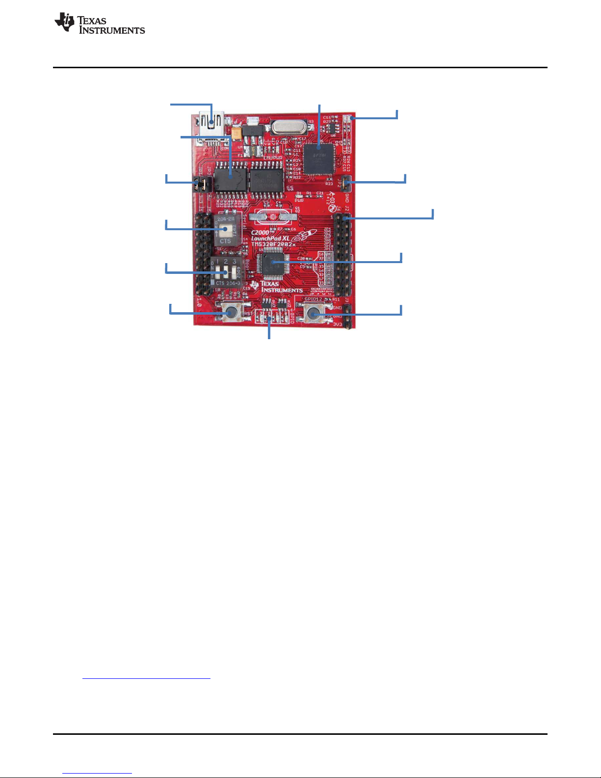
USB Connection
JTAG
Isolation
Jumpers:
JP1 and JP3
S4 Serial
Connection Switch
S1 Boot
Selection Switch
CPU Reset
Push Button
JTAG Emulator
Circuitry
Four LEDs
Serial
TX/RX
LEDs
Jumper: JP2
20 PCB Pins
(doubled-sided male connectors)
Pre-Programmed C2000
Piccolo TMS320F28027
MCU
Programmable
Push Button:
GPIO12
www.ti.com
Installation
Figure 1. LAUNCHXL-F28027 Board Overview
1.2 Kit Contents
The LAUNCHXL-F28027 C2000 LaunchPad experimenter kit includes the following items:
• C2000 LaunchPad Board (LAUNCHXL-F28027)
• Mini USB-B Cable, 0.5m
• Quick Start Guide
1.3 Revisions
The first production revision of the LAUNCHXL-F28027 C2000 Piccolo LaunchPad, version 1.0, was
released in July of 2012 and is currently the only revision available.
2 Installation
The C2000 LaunchPad installation consists of three easy steps:
1. Download Code Composer Studio and controlSUITE™.
2. Install Code Composer Studio and controlSUITE.
3. Connect and install the C2000 LaunchPad to the PC.
Now the LaunchPad is ready to develop applications or run the pre-programmed demo.
2.1 Download the Required Software
Code Composer Studio IDE is available for free without any restriction when used with the XDS100
emulator on the C2000 LaunchPad. The software can be downloaded from the C2000 LaunchPad page at
www.ti.com/c2000-launchpad. At this site, you can also download a copy of controlSUITE that includes
drivers, examples, and other support software needed to get started.
SPRUHH2A–July 2012–Revised January 2014 LAUNCHXL-F28027 C2000 Piccolo LaunchPad Experimenter Kit
Submit Documentation Feedback
5
Copyright © 2012–2014, Texas Instruments Incorporated
Page 6

Getting Started with the LAUNCHXL-F28027
2.2 Install the Software
Once downloaded, install Code Composer Studio and the controlSUITE package.
2.3 Install the Hardware
After Code Composer Studio is installed, plug the supplied USB cable into the C2000 LaunchPad board
and into an available USB port on your computer.
Windows®will automatically detect the hardware and ask you to install software drivers. Let Windows run
a search for the drivers and automatically install them. After Windows successfully installs the drivers for
the integrated XDS100v2 emulator, your LaunchPad is now ready for use.
3 Getting Started with the LAUNCHXL-F28027
3.1 Getting Started
The first time the LAUNCHXL-F28027 is used, a demo application automatically starts when the board is
powered from a USB host. If your board does not start the demo application, try placing S1 in the following
positions and resetting the board: UP - UP - DOWN. To start the demo, connect the LAUNCHXL-F28027
with the included mini-USB cable to a free USB port. The demo application starts with the LEDs flashing
to show the device is active.
3.2 Demo Application, Internal Temperature Measurement
The LAUNCHXL-F28027 includes a pre-programmed TMS320F28027 device. When the LaunchPad is
connected via USB, the demo starts with an LED flash sequence that points toward S3. Press S3 to start
the temperature measurement mode.
A reference temperature is taken at the beginning of this mode and the LEDs of the LaunchPad are used
to display any difference between the current temperature and the reference temperature. Initially, the
LED connected to GPIO3 is lit to indicate an 8 in binary, which corresponds to the current temperature
being equal to the reference temperature. As the temperature drifts away from the reference, the
difference is displayed as a binary increment or decrement of the nibble wide LED display. For instance, if
the reference temperature was 30ºC and the current temperature is 33ºC, the LEDs would be (from left to
right) ON, OFF, ON, and ON which would be 11 in binary (33-30=3 and 11-8=3). A new reference
temperature may be set at any time by pressing S3 again.
In addition to the LED display, temperature information is also displayed on your PC through the
USB/UART connection. To view the UART information on your PC, first figure out the COM port
associated with the LaunchPad. To do this in Windows, right click on My Computer and click on
Properties. In the dialog box that appears, click on the Hardware tab and open Device Manager. Look for
an entry under Ports (COM & LPT) titled "USB Serial Port (COMX)", where X is a number. Remember this
number for when you open a serial terminal. The demo applications UART data was written and debugged
using PuTTY, and for the best user experience we recommend you use PuTTY to view the UART data.
Open your serial terminal program and open the COM port you found previously in device manager with
the following settings: 115200 Baud, 8 data bits, no parity, 1 stop bit. After opening the serial port in your
serial terminal, reset the Launchpad with the reset push button and observe the serial terminal for a
surprise.
www.ti.com
3.3 Program and Debug the Temperature Measurement Demo Application
The project and associated source code for the C2000 Piccolo LaunchPad demo is included in the
controlSUITE software package and should automatically be found by the TI Resource Explorer in Code
Composer Studio v5. In the resource explorer, open the controlSUITE folder and then the Development
Tools entry and look for the C2000 LaunchPad line item. Expand this item and LAUNCHXL-F28027, then
select the LaunchPad Demo Application. Follow the steps in the main pane of the resource explorer to
import, build, debug, and run this application.
4 Hardware Configuration
The C2000 LaunchPad gives users several options as to how to configure the board.
6
LAUNCHXL-F28027 C2000 Piccolo LaunchPad Experimenter Kit SPRUHH2A–July 2012–Revised January 2014
Copyright © 2012–2014, Texas Instruments Incorporated
Submit Documentation Feedback
Page 7

www.ti.com
4.1 Power Domain
The C2000 LaunchPad has two separate power domains for the purpose of allowing JTAG isolation.
Jumpers JP1, JP2, and JP3 configure whether the USB power is passed to the target device.
4.2 Serial Connectivity
The LAUNCHXL-F28027 has a USB to UART adapter built in. This makes it easy to print debug
information back to the host PC even in isolated environments. However, in some cases the user may
wish to connect the Piccolo SCI peripheral (C2000 UART peripheral) to a BoosterPack or other hardware
via the header pins. If the SCI pins are connected to both the header pins, the XDS100 UART channel
contention would exist and the pins would not be driven to the correct voltage levels. To solve this issue
we have included a switch to allow the user to disconnect the Piccolo serial pins from the XDS100 UART
connection. When S4 is in the up position, the Piccolo device's SCI is connected to the XDS100 and you
are able to receive and send serial information from or to the board. When S4 is in the down position, the
Piccolo device's SCI is disconnected from the XDS100 and BoosterPacks, which use serial
communication, and can communicate with the Piccolo device.
4.3 Boot Mode Selection
The LaunchPad's F28027 device includes a boot ROM that performs some basic start-up checks and
allows for the device to boot in many different ways. Most users will either want to perform an emulation
boot or a boot to flash (if they are running the application standalone). S1 has been provided to allow
users to easily configure the pins that the bootROM checks to make this decision. The switches on S1
correspond to:
Hardware Configuration
Jumper Power Domain
JP1 3.3 V
JP2 Ground
JP3 5 V
Keep in mind that the debugger does not connect if the device is not in the emulation boot mode (TRST
switch in the up position). More information about boot mode selection can be found in the
TMS320x2802x Piccolo Boot ROM Reference Guide (SPRUFN6).
4.4 Connecting a Crystal
Although the Piccolo device present on the LAUNCHXL-F28027 has an internal oscillator — and for most
applications this is sufficient — the LaunchPad offers a footprint for surface mount or through-hole HC-49
crystals for users who require a more precise clock. If you wish to use an external crystal, solder the
crystal to the Q1/Q2 footprint and appropriate load capacitors to the C3 and C4 footprints. You also need
to configure the device to use the external oscillator in software.
4.5 Connecting a Satellite Board
The C2000 LaunchPad is the perfect experimenter board to start hardware development with the F2802x
devices. Connectors J1, J2, J5, and J6 and the power supply at J3 are aligned in a 0.1-in (2.54-mm) grid
to allow an easy and inexpensive development of a breadboard extension module. These satellite boards
can access all of the GPIO and analog signals. The alignment of the connectors and the pin out can be
found in Section 5.
Switch Function
1 GPIO34
2 GPIO37
3 TRSTn
SPRUHH2A–July 2012–Revised January 2014 LAUNCHXL-F28027 C2000 Piccolo LaunchPad Experimenter Kit
Submit Documentation Feedback
7
Copyright © 2012–2014, Texas Instruments Incorporated
Page 8
LAUNCHXL-F28027 Hardware
www.ti.com
4.6 Device Migration Path
Applications developed on the LAUNCHXL-F28027 can easily be migrated to any of these lower cost
devices in the F2802x family:
Part Number Description
TMS320F28027
TMS320F28026 32-bit Real Time Microcontroller, 60 MHz, 16K Flash, 6K RAM, 4 HRPWM
TMS320F28023 32-bit Real Time Microcontroller, 50 MHz, 32K Flash, 6K RAM, 4 HRPWM
TMS320F28022 32-bit Real Time Microcontroller, 50 MHz, 16K Flash, 6K RAM, 4 HRPWM
TMS320F28021 32-bit Real Time Microcontroller, 40 MHz, 32K Flash, 5K RAM
TMS320F28020 32-bit Real Time Microcontroller, 40 MHz, 16K Flash, 3K RAM
TMS320F280200 32-bit Real Time Microcontroller, 40 MHz, 8K Flash, 3K RAM
(1)
This device is present on the LAUNCHXL-F28027.
(1)
32-bit Real Time Microcontroller, 60 MHz, 32K Flash, 6K RAM, 4 HRPWM
5 LAUNCHXL-F28027 Hardware
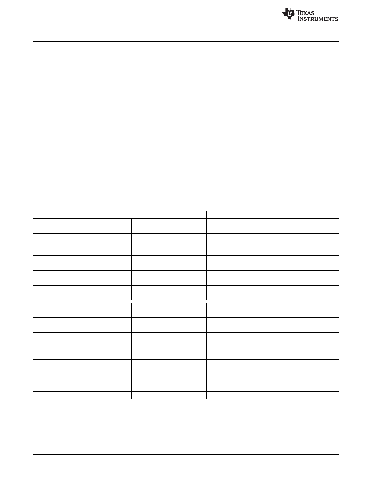
5.1 Device Pin Out
Table 1 lists the pin out and pin mux options for the C2000 LaunchPad.
Table 1. C2000 LaunchPad Pin Out and Pin Mux Options
Mux Value Mux Value
3 2 1 0 J1 Pin J5 Pin 0 1 2 3
+3.3V 1 1 +5V
ADCINA6 2 2 GND
TZ2 SDAA SCIRXDA GPIO28 3 3 ADCINA7
TZ3 SCLA SCITXDA GPIO29 4 4 ADCINA3
Rsvd Rsvd COMP2OUT GPIO34 5 5 ADCINA1
ADCINA4 6 6 ADCINA0
SCITXDA SPICLK GPIO18 7 7 ADCINB1
ADCINA2 8 8 ADCINB3
ADCINB2 9 9 ADCINB7
ADCINB4 10 10 NC
3 2 1 0 J6 Pin J2 Pin 0 1 2 3
Rsvd Rsvd EPWM1A GPIO0 1 1 GND
COMP1OUT Rsvd EPWM1B GPIO1 2 2 GPIO19 SPISTEA SCIRXDA ECAP1
Rsvd Rsvd EPWM2A GPIO2 3 3 GPIO12 TZ1 SCITXDA Rsvd
COMP2OUT Rsvd EPWM2B GPIO3 4 4 NC
Rsvd Rsvd EPWM3A GPIO4 5 5 RESET#
ECAP1 Rsvd EPWM3B GPIO5 6 6 GPIO16/32 SPISIMOA/ Rsvd/ TZ2/
TZ2/ Rsvd/ SPISIMOA/ GPIO16/32 7 7 GPIO17/33 SPISOMIA/ Rsvd/ TZ3/
ADCSOCA EPWMSYNCI SDAA SCLA EPWMSYNCO ADCSOCB
TZ3/ Rsvd/ SPISOMIA/ GPIO17/33 8 8 GPIO6 EPWM4A EPWMSYNCI EPWMSYNCO
ADCSOCB EPWMSYNCO SCLA
NC 9 9 GPIO7 EPWM4B SCIRXDA Rsvd
NC 10 10 ADCINB6
SDAA EPWMSYNCI ADCSOCA
8
LAUNCHXL-F28027 C2000 Piccolo LaunchPad Experimenter Kit SPRUHH2A–July 2012–Revised January 2014
Copyright © 2012–2014, Texas Instruments Incorporated
Submit Documentation Feedback
Page 9

Emulator - XDS100v2
1.0C2000_LaunchPad.sch
10k
2.2k
3.3u
0.1u
93
0.1u0.1u0.1u
12k
1k
ISO7231
ISO7240
AGND
AGND
AGND
AGND
AGND
AGND
GND
GND
AGND
1u 0.1u
AGND
AGND
1k
AGND
330
330
12M
36p 36p
+3V3
0
0
0
0
0
0
0
0
0
TLV1117-33
100u
AGND
+3V3
AGND
AGND
AGND
AGND
4.7u 4.7u
AGND
AGND
820
AGND
500mA
+5V
R29
R31
C15
C16
6
2
CLK
4
DO
1
DI
3
CS
5
VCC
GND
U8
VREGIN
P$50
USBDM
P$7
USBDP
P$8
REF
P$6
RESET#
P$14
OSCI
P$2
OSCO
P$3
EECS
P$63
EECLK
P$62
EEDATA
P$61
TEST
P$13
AGND
P$10
GND1
P$1
GND2
P$5
GND3
P$11
GND4
P$15
PWREN#
P$60
SUSPEND#
P$36
BCBUS3
P$54
BCBUS2
P$53
BCBUS1
P$52
BCBUS0
P$48
BDBUS7
P$46
BDBUS6
P$45
BDBUS5
P$44
BDBUS4
P$43
BDBUS3
P$41
BDBUS2
P$40
BDBUS1
P$39
BDBUS0
P$38
ACBUS3
P$29
ACBUS2
P$28
ACBUS1
P$27
ACBUS0
P$26
ADBUS7
P$24
ADBUS6
P$23
ADBUS5
P$22
ADBUS4
P$21
ADBUS3
P$19
ADBUS2
P$18
ADBUS1
P$17
ADBUS0
P$16
VCCIO1
P$20
VCORE2
P$37
VCORE1
P$12
VPHY
P$4
U6
FT2232H
ACBUS4
P$30
ACBUS5
P$32
ACBUS6
P$33
ACBUS7
P$34
BCBUS4
P$55
BCBUS5
P$57
BCBUS6
P$58
BCBUS7
P$59
GND5
P$25
GND6
P$35
GND7
P$47
GND8
P$51
VREGOUT
P$49
VPLL
P$9
VCORE3
P$64
VCCIO2
P$31
VCCIO3
P$42
VCCIO4
P$56
TH
TH
C14C13C12
R24
R22
1
2
3
4
5
VCC1
1
VCC2
16
GND1
2
GND1
8
GND2
15
GND2
9
INA
3
INB
4
OUTC
5
NC1
6
EN1
7
EN2
10
OUTA
14
OUTB
13
INC
12
NC2
11
U7
VCC1
1
VCC2
16
GND1
2
GND1
8
GND2
15
GND2
9
INA
3
INB
4
INC
5
IND
6
NC
7
EN
10
OUTA
14
OUTB
13
OUTC
12
OUTD
11
U5
C7 C9
R23
D7
D8
R26
R27
Q3
C17 C18
R21
R20
R19
R18
R16
R28
R30
R32
R25
VIN
3
VOUT1
2
VOUT2
4
ADJ/GND
1
U4
C8
1
JP1
2
1
JP2
2
C10 C11
L2
L1
D6
R17
F1
1
JP3
2
D-
D-
D+
D+
USBVCC
USBVCC
USBVCC
TCK
TDI
TDO
TMS
FTDI_CS
FTDI_CS
FTDI_CLK
FTDI_CLK
FTDI_DATA
FTDI_DATA
FTDI_DATA
FTDI_1V8
PWREN#
SUSPEND#
SCI_RX
SCI_TX
FTDI_3V3
FTDI_3V3
FTDI_3V3
FTDI_3V3
FTDI_3V3
FTDI_3V3
FTDI_3V3
FTDI_3V3
JTAG_TRST
Array
EEPROM
A
B
C
D
E
A
B
C
D
E
1 2 3 4 5 6
www.ti.com
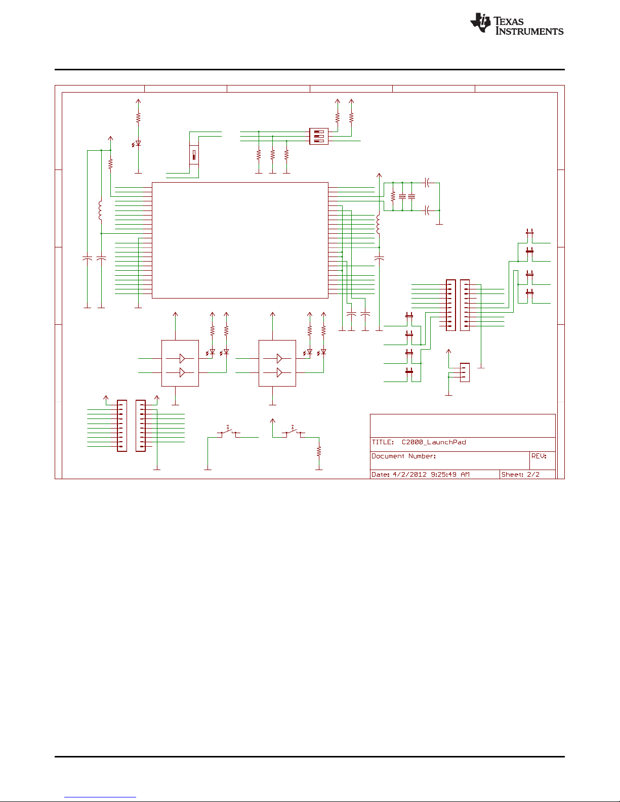
5.2 Schematics
Figure 2 and Figure 3 show the C2000 LaunchPad schematics sheets.
LAUNCHXL-F28027 Hardware
Figure 2. C2000 LaunchPad Schematic—Sheet 1 of 2
SPRUHH2A–July 2012–Revised January 2014 LAUNCHXL-F28027 C2000 Piccolo LaunchPad Experimenter Kit
Submit Documentation Feedback
Copyright © 2012–2014, Texas Instruments Incorporated
9
Page 10
SCI_RX
SCI_TX
SPI_CLK
SPI_MISO
SPI_MOSI
SPI_MISO
SPI_MOSI
1.0
Piccolo F2802x
C2000_LaunchPad.sch
+3V3
TMS320F28027PT
36p
36p
1M
GND
GND
+3V3
GND
2.2k
2.2k
2.2k
820
820
+3V3
+3V3
GND GND
2.2u 2.2u
GND GND
FSMJSMAFSMJSMA
10k
+3V3
GNDGND
SN74LVC2G07
330
330
+3V3
+3V3
+3V3
GND
SN74LVC2G07
330
330
+3V3
+3V3
+3V3
GND
820
+3V3
GND
219-03
2.2k
GND
204-1
2.2u
GND
2.2u
GND
2.2u
GND
GND
+3V3
+3V3
+5V
GND
GND
GPIO29/SCITXD A/SCLA/TX3#
1
TRST#
2
XRS#
3
ADCINA6/AIO6
4
ADCINA4/COMP 2A/AIO4
5
ADCINA7
6
ADCINA3
7
ADCINA1
8
ADCINA2/COMP 1A/AIO2
9
ADCINA0/VREF HI
10
VDDA
11
VSSA/VREFLO
12
ADCINB1
13
ADCINB2/COMP 1B/AIO10
14
ADCINB3
15
ADCINB4/COMP 2B/AIO12
16
ADCINB6/AIO14
17
ADCINB7
18
GPIO34/COMP2 OUT
19
TDI
20
TMS
21
TDO
22
TCK
23
GPIO18/SPICLKA /SCITXDA/XCLKOUT
24
GPIO19/XCLKIN /SPISTEA#/SCIRXDA/ECAP1
25
GPIO17/SPISOM IA/TZ3#
26
GPIO16/SPISIMO A/TZ2#
27
GPIO1/EPW M1B/COMP1OUT
28
GPIO0/EPW M1A
29
TEST
30
GPIO32/SDAA/E PWMSYNCI/ADCSOCAO#
31
VDD1
32
VSS1
33
VREGENZ#
34
VDDIO
35
GPIO33/SCLA/EP WMSYNCO/ADCSOCBO #
36
GPIO2/EPW M2A
37
GPIO3/EPW M2B/COMP2OUT
38
GPIO4/EPW M3A
39
GPIO5/EPW M3B/ECAP1
40
GPIO6/EPW M4A/EPWMSYNCI/EPW MSYNCO
41
GPIO7/EPW M4B/SCIRXDA
42
VDD2
43
VSS2
44
X1
45
X2
46
GPIO12/TZ1#/SC ITXDA
47
GPIO28/SCIRXD A/SDAA/TZ2#
48
U1
Q1
Q2
C4
C3
R7
R6
R8
R9
R4
R5
C5 C 6
S3S2
D2
D4
R11
1A
1
2A
3
2Y
4
1Y
6
VCC
5
GND
2
U2
R12
R13
D3
D5
1A
1
2A
3
2Y
4
1Y
6
VCC
5
GND
2
U3
R14
R15
D1
R1
4
5
61
2
3
S1
R10
P$2
P$1
S4
P$3
P$4
L3
L4
C19 C20C21
1
2
3
J3
1
2
3
4
5
6
7
8
9
10
J1
1
2
3
4
5
6
7
8
9
10
J5
1
2
3
4
5
6
7
8
9
10
J6
1
2
3
4
5
6
7
8
9
10
J2
1
JP4
2
1
JP5
2
1
JP6
2
1
JP7
2
1
JP8
2
1
JP9
2
1
JP10
2
1
JP11
2
TCK
TDI
TDO
TDO
TMS
SCI_RX
SCI_TX
TRST
TRST
RESET#
RESET#
RESET#
GPIO34
GPIO34
GPIO34
GPIO19
GPIO19GPIO17
GPIO17
GPIO17
GPIO16
GPIO16
GPIO16
GPIO1
GPIO1
GPIO1
GPIO0
GPIO0
GPIO0
GPIO32
GPIO32
GPIO32
GPIO2
GPIO2
GPIO2
GPIO3
GPIO3
GPIO3
GPIO4
GPIO4
GPIO5
GPIO5
GPIO6
GPIO6
GPIO7
GPIO7
GPIO12
GPIO12
GPIO12
GPIO28
GPIO28
GPIO28
GPIO29
GPIO29
GPIO29
ADCINA6
ADCINA6
ADCINA4
ADCINA4
ADCINA1
ADCINA1
ADCINA2
ADCINA2
ADCINB1
ADCINB1
ADCINB2
ADCINB2
ADCINB4
ADCINB4
ADCINB6
ADCINB6
GPIO18
GPIO18
GPIO33
GPIO33
GPIO33
JTAG_TRST
ADCINA7
ADCINA7
ADCINA3
ADCINA3
ADCINA0
ADCINA0
ADCINB3
ADCINB3
ADCINB7
ADCINB7
123
ON
1
ON
A
B
C
D
E
A
B
C
D
E
1 2 3 4 5 6
LAUNCHXL-F28027 Hardware
www.ti.com
10
LAUNCHXL-F28027 C2000 Piccolo LaunchPad Experimenter Kit SPRUHH2A–July 2012–Revised January 2014
Figure 3. C2000 LaunchPad Schematic—Sheet 2 of 2
Copyright © 2012–2014, Texas Instruments Incorporated
Submit Documentation Feedback
Page 11

www.ti.com
5.3 PCB Layout
Figure 4, Figure 5, and Figure 6 show the LAUNCHXL-F28027 PCB layout.
LAUNCHXL-F28027 Hardware
Figure 4. LAUNCHXL-F28027 PCB Layout—Top Layer
Figure 5. LAUNCHXL-F28027 PCB Layout—Bottom Layer
Figure 6. LAUNCHXL-F28027 PCB Layout—Silkscreen Image
SPRUHH2A–July 2012–Revised January 2014 LAUNCHXL-F28027 C2000 Piccolo LaunchPad Experimenter Kit
Submit Documentation Feedback
11
Copyright © 2012–2014, Texas Instruments Incorporated
Page 12

LAUNCHXL-F28027 Hardware
5.4 Bill of Materials (BOM)
Table 2 lists the LAUNCHXL-F28027 bill of materials.
Reference Board Description
R12, R13, R14, R15, R26, R27 6 RES 330 Ω 1/10W 5% 0402 SMD
R1, R4, R5, R17 4 RES 820 Ω 1/10W 5% 0402 SMD
R22, R23 2 RES 1.0K Ω 1/10W 5% 0402 SMD
R6, R8, R9, R10, R31 5 RES 2.2K Ω 1/10W 5% 0402 SMD
R11, R29 2 RES 10K Ω 1/10W 5% 0402 SMD
R24 1 RES 12K Ω 1/16W .5% 0402 SMD
R7 1 RES 1.0M Ω 1/10W 5% 0402 SMD
R16, R18, R19, R20, R21, R25, R28, R30, 9 RES 0.0 Ω 1/4W 1206 SMD
R32
L1, L2 2 FERRITE BEAD 600 Ω 0402
L3 1 FERRITE BEAD 220 Ω 0402
L4 1 FERRITE CHIP 60 Ω 1.5A 0402
C9, C12, C13, C14, C16 5 CAP .10 µF 16 V CERAMIC Y5V 0402
C7 1 CAP CER 1.0 µF 6.3 V X5R 20% 0402
C5, C6, C19, C20, C21 5 CAP CER 2.2 µF 6.3 V 20% X5R 0402
C15 1 CAP CER 3.3 µF 4.0 V X5R 0402
C10, C11 2 CAP CER 4.7 µF 4 V X5R 0402
C3, C4 2 CAP CER 36PF 50 V C0G 0402
C17, C18 2 CAP CER 36PF 50 V C0G 0402
C8 1 CAP TANTALUM 100 µF 6.3 V 10% SMD
F1 1 PTC RESETTABLE .50A 15 V 1812
S1 1 SWITCH DIP 3POS TOP SLIDE SMT
S4 1 SWITCH DIP DPST 1POS SMT
S2, S3 2 SW TACT SPST-NO MOM 160GF SMD
Q1, Q2 1 Crystal
Q3 1 CRYSTAL 12.0000 MHZ 18PF SMD
D6 1 LED RED HIGH BRIGHT ESS SMD
D1 1 LED GREEN HIGH BRIGHT ESS SMD
D2, D3, D4, D5, D7, D8 6 LED BLUE HIGH BRIGHT ESS SMD
JP1, JP2, JP3 3 BERGSTIK II .100" SR STRAIGHT
J1 and J5, J2 and J6 2 CONN HEADER .100 DUAL STR 20POS
J3 1 CONN HEADER .100 SNGL STR 3POS
CON1 1 CONN RECEPT MINI-USB TYPE B SMT
U4 1 IC LDO REG 800MA 3.3 V SOT223-4
U2, U3 2 IC BUFF/DVR DL NON-INV SOT236
U5 1 ISOLAT DGTL 2.5 KVRMS 4CH 16-SOIC
U7 1 ISOLAT DGTL 3 KVRMS 3CH 16-SOIC
U6 1 IC USB HS DUAL UART and FIFO 64-QFN
U8 1 IC EEPROM 2KBIT 3 MHZ SOT23-6
U1 1 IC MCU 32 BIT 64KB FLASH 48LQFP
www.ti.com
Table 2. LAUNCHXL-F28027 Bill of Materials
Quantity
per
12
LAUNCHXL-F28027 C2000 Piccolo LaunchPad Experimenter Kit SPRUHH2A–July 2012–Revised January 2014
Submit Documentation Feedback
Copyright © 2012–2014, Texas Instruments Incorporated
Page 13

www.ti.com
6 Suggested Reading
The following documents describe the C2000 devices. Copies of these documents are available on the
Internet at http://www.ti.com/c2000 and www.ti.com/c2000-launchpad, or click on the links below:
• TMS320F28027/28026/28023/28022/28021/28020/280200 Piccolo Microcontrollers Data Manual
(SPRS523)
• TMS320F28027/28026/28023/28022/28021/28020/2802x0 Piccolo MCU Silicon Errata (SPRZ292)
• TMS320x2802x, 2803x Piccolo Analog-to-Digital Converter (ADC) and Comparator Reference Guide
(SPRUGE5)
• TMS320x2802x, 2803x Piccolo High Resolution Pulse Width Modulator (HRPWM) Reference Guide
(SPRUGE8)
• TMS320x2802x, 2803x Piccolo Inter-Integrated Circuit (I2C) Reference Guide (SPRUFZ9)
• TMS320x2802x, 2803x Piccolo Enhanced Pulse Width Modulator (ePWM) Module Reference Guide
(SPRUGE9)
• TMS320x2802x/TMS320F2802xx Piccolo System Control and Interrupts Reference Guide (SPRUFN3)
• TMS320x2802x Piccolo Boot ROM Reference Guide (SPRUFN6)
• TMS320x2802x, 2803x Piccolo Serial Communications Interface (SCI) Reference Guide (SPRUGH1)
• TMS320x2802x, 2803x Piccolo Enhanced Capture (eCAP) Module Reference Guide (SPRUFZ8)
• TMS320C28x Instruction Set Simulator Technical Overview (SPRU608)
• TMS320C28x Optimizing C/C++ Compiler v6.1 User's Guide (SPRU514)
• TMS320C28x Assembly Language Tools v6.1 User's Guide (SPRU513)
Suggested Reading
SPRUHH2A–July 2012–Revised January 2014 LAUNCHXL-F28027 C2000 Piccolo LaunchPad Experimenter Kit
Submit Documentation Feedback
13
Copyright © 2012–2014, Texas Instruments Incorporated
Page 14

Frequently Asked Questions (FAQ)
7 Frequently Asked Questions (FAQ)
1. Can other programming and debug tools (such as an XDS510 emulator) be used with the C2000
LaunchPad?
While a user could potentially connect an external emulator to the F28027 device present on the
LaunchPad, it would require some rework of the board. It is recommended that users who want to use
an external emulator purchase a controlCard and docking station that includes an external JTAG
connector.
2. What versions of Code Composer Studio can be used to develop software for the C2000 LaunchPad?
It is highly recommend that novice users develop applications with Code Composer Studio v5. The
drivers, examples, and other associated software are tailored to make the user experience as smooth
as possible in Code Composer Studio v5. However, there is nothing to prevent a user from creating
projects in Code Composer Studio v3 or v4 with the source files available in controlSUITE. Keep in
mind that all the projects for the C2000 LaunchPad are Code Composer Studio v5 projects and will not
import into Code Composer Studio v3 or v4. Only expert users should attempt to use the LaunchPad
with Code Composer Studio v3 or v4.
3. Why can’t I connect to the LaunchPad in Code Composer Studio?
There are a number of things that could cause this and they all have an easy fix.
• Is S1 switch 3 in the down position?
This is the TRST pin that enables and disables JTAG functionality on the chip. This switch must be
in the up position for the emulator to be able to connect.
• Are both power LEDs lit?
The board has two power domains because of the isolated JTAG interface. For low-voltage
application development, JTAG isolation is not needed and the power domains can be combined to
allow for convenience (that is, the board can be powered completely through the USB). Ensure that
jumpers are placed on the posts of JP1, JP2, and JP3.
• Are drivers correctly installed for the XDS100v2 present on the LaunchPad?
Right click on My Computer and select properties. Navigate to the Hardware tab in the dialog box
and open the device manager. Scroll to the bottom of the list and expand the USB Serial Bus
controllers item. Are there two entries for TI XDS100 Channel A/B? If not, try unplugging and
replugging in the board. Does Windows give you any messages in the system tray? In Device
Manger, do either of the entries have a yellow exclamation mark over their icon? If so, try
reinstalling the drivers.
4. Why is the serial connection not working?
There are a few things that could cause this and they are easy to fix.
• Is S4 in the up position?
S4 connects the F28027 device serial peripheral to the XDS100 serial port, so this switch must be
turned on (up) for serial connectivity to function.
• Are you using the correct COM port?
Right click on My Computer and select properties. Navigate to the Hardware tab in the dialog box
and open the device manager. Scroll to Ports (COM & LPT) and expand this entry. Is there a USB
Serial Port listed? If so, read the COM number to the right of the entry; this is the COM number you
should be using.
• Are you using the correct baud rate?
Most, if not all, of the examples are configured for a baud rate of 115200 when the CPU is running
at 60 MHz. If you have changed the PLL settings or written your own application you may have to
recalculate the baud rate for your specific application. For information on how to do this, see the
TMS320x2802x, 2803x Piccolo Serial Communications Interface (SCI) Reference Guide
(SPRUGH1).
www.ti.com
14
LAUNCHXL-F28027 C2000 Piccolo LaunchPad Experimenter Kit SPRUHH2A–July 2012–Revised January 2014
Copyright © 2012–2014, Texas Instruments Incorporated
Submit Documentation Feedback
Page 15

IMPORTANT NOTICE
Texas Instruments Incorporated and its subsidiaries (TI) reserve the right to make corrections, enhancements, improvements and other
changes to its semiconductor products and services per JESD46, latest issue, and to discontinue any product or service per JESD48, latest
issue. Buyers should obtain the latest relevant information before placing orders and should verify that such information is current and
complete. All semiconductor products (also referred to herein as “components”) are sold subject to TI’s terms and conditions of sale
supplied at the time of order acknowledgment.
TI warrants performance of its components to the specifications applicable at the time of sale, in accordance with the warranty in TI’s terms
and conditions of sale of semiconductor products. Testing and other quality control techniques are used to the extent TI deems necessary
to support this warranty. Except where mandated by applicable law, testing of all parameters of each component is not necessarily
performed.
TI assumes no liability for applications assistance or the design of Buyers’ products. Buyers are responsible for their products and
applications using TI components. To minimize the risks associated with Buyers’ products and applications, Buyers should provide
adequate design and operating safeguards.
TI does not warrant or represent that any license, either express or implied, is granted under any patent right, copyright, mask work right, or
other intellectual property right relating to any combination, machine, or process in which TI components or services are used. Information
published by TI regarding third-party products or services does not constitute a license to use such products or services or a warranty or
endorsement thereof. Use of such information may require a license from a third party under the patents or other intellectual property of the
third party, or a license from TI under the patents or other intellectual property of TI.
Reproduction of significant portions of TI information in TI data books or data sheets is permissible only if reproduction is without alteration
and is accompanied by all associated warranties, conditions, limitations, and notices. TI is not responsible or liable for such altered
documentation. Information of third parties may be subject to additional restrictions.
Resale of TI components or services with statements different from or beyond the parameters stated by TI for that component or service
voids all express and any implied warranties for the associated TI component or service and is an unfair and deceptive business practice.
TI is not responsible or liable for any such statements.
Buyer acknowledges and agrees that it is solely responsible for compliance with all legal, regulatory and safety-related requirements
concerning its products, and any use of TI components in its applications, notwithstanding any applications-related information or support
that may be provided by TI. Buyer represents and agrees that it has all the necessary expertise to create and implement safeguards which
anticipate dangerous consequences of failures, monitor failures and their consequences, lessen the likelihood of failures that might cause
harm and take appropriate remedial actions. Buyer will fully indemnify TI and its representatives against any damages arising out of the use
of any TI components in safety-critical applications.
In some cases, TI components may be promoted specifically to facilitate safety-related applications. With such components, TI’s goal is to
help enable customers to design and create their own end-product solutions that meet applicable functional safety standards and
requirements. Nonetheless, such components are subject to these terms.
No TI components are authorized for use in FDA Class III (or similar life-critical medical equipment) unless authorized officers of the parties
have executed a special agreement specifically governing such use.
Only those TI components which TI has specifically designated as military grade or “enhanced plastic” are designed and intended for use in
military/aerospace applications or environments. Buyer acknowledges and agrees that any military or aerospace use of TI components
which have not been so designated is solely at the Buyer's risk, and that Buyer is solely responsible for compliance with all legal and
regulatory requirements in connection with such use.
TI has specifically designated certain components as meeting ISO/TS16949 requirements, mainly for automotive use. In any case of use of
non-designated products, TI will not be responsible for any failure to meet ISO/TS16949.
Products Applications
Audio www.ti.com/audio Automotive and Transportation www.ti.com/automotive
Amplifiers amplifier.ti.com Communications and Telecom www.ti.com/communications
Data Converters dataconverter.ti.com Computers and Peripherals www.ti.com/computers
DLP® Products www.dlp.com Consumer Electronics www.ti.com/consumer-apps
DSP dsp.ti.com Energy and Lighting www.ti.com/energy
Clocks and Timers www.ti.com/clocks Industrial www.ti.com/industrial
Interface interface.ti.com Medical www.ti.com/medical
Logic logic.ti.com Security www.ti.com/security
Power Mgmt power.ti.com Space, Avionics and Defense www.ti.com/space-avionics-defense
Microcontrollers microcontroller.ti.com Video and Imaging www.ti.com/video
RFID www.ti-rfid.com
OMAP Applications Processors www.ti.com/omap TI E2E Community e2e.ti.com
Wireless Connectivity www.ti.com/wirelessconnectivity
Mailing Address: Texas Instruments, Post Office Box 655303, Dallas, Texas 75265
Copyright © 2014, Texas Instruments Incorporated
Page 16

Mouser Electronics
Authorized Distributor
Click to View Pricing, Inventory, Delivery & Lifecycle Information:
Texas Instruments:
LAUNCHXL-F28027
 Loading...