

Page 1

Maintenance Manual
E
xtensa
TM
60x & 65x Series
Notebook Computers
9813564-0001, Rev. A
October 1996
Page 2

Model 60x Maintenance Data
A.1 Introduction
This section contains model-dependent maintenance data for the Extensa Model 60x
Series Notebook Computers. For information common to all members of the Extensa
600 Series, refer to Sections 1 through 6 of this manual.
A.2 Model 60x Features Summary
The Extensa 60x Series Notebook Computers has either a 10.4-inch VGA or 12.1-inch
SVGA Display, comes standard with a 810 MB Hard Drive and is powered by a 120
MHz Pentium processor. Refer to Section 1 for a more detailed description of Extensa
600 Series features.
A.3 Field-Replaceable Units (FRUs)
Table A-1 lists and describes the various FRUs for the Extensa 60x Series. For FRU
removal/replacement procedures, refer to Section 6 of this manual.
A
As shown in Figure A-1, all members of the Extensa 60x Series Notebook Computers
contain two major assemblies:
♦ System Base Assembly
♦ Cover-Display Assembly
Model 60x Maintenance Data A-1
Page 3

Figure A-1 Extensa 600 Series Assemblies
A.3.1 Cover-Display Assembly
The Cover-Display Assembly shown in Figure A-2, contains the LCD screen, DC-AC
Inverter Board, DC-DC Inverter Board, bezel LCD cover and various other components
as listed in Table A-1.
Display Assembly
Base Assembly
A-2 Model 60x Maintenance Data
Page 4

.
LCD Panel
DC-AC Inverter
Board Assembly
DC-DC Inverter
Board
Display Cable
Display Assembly
Shown with
Bezel Removed
Figure A-2 Display FRUs
Table A-1 Top Cover Assembly Field-Replaceable Units (FRUs)
FRU Description Assembly/
Disassembly
Paragraph
LCD Panel, 10.3", ASTN 6.5.24 9813525-0001
Display Back Cover, 10.4" Ref 9813503-0001
Display Back Cover, 12.1" Ref 9813548-0001
LCD Round Bumper Ref 9813550-0001
AC-DC Inverter Board 6.5.23 9811361-0001
DC-DC Inverter Board 6.5.23 9813531-0001
Display Cable Assembly, 10.4" Display Ref 9813502-0001
Display Cable Assembly, 12.1" Display Ref 9813548-0001
TI Part No.
Display Bezel, 10.4" 6.5.22 9804448-0003
Model 60x Maintenance Data A-3
Page 5

Table A-1 Top Cover Assembly Field-Replaceable Units (FRUs)
FRU Description Assembly/
TI Part No.
Disassembly
Paragraph
Display Bezel, 12.1" 6.5.22 9813480-0001
LCD Screw Cover Right Ref 9813551-0001
LCD Screw Cover Left Ref 9813552-0001
Left Hinge, ASTN 10.4" Ref 9813526-0001
Right Hinge, DSTN, 12.1" Ref 9813521-0001
A.3.2 System Base Assembly
As shown in Figure A-3, the System Base Assembly houses a variety of field-replaceable
subassemblies and components. The various assemblies and reference paragraph
numbers containing removal/replacement procedures are listed in Table A-2.
A-4 Model 60x Maintenance Data
Page 6

Keyboard
Assembly
Touchpad
Assembly
Heat Sin k
Assembly
Motherboard
Assembly
Power Supply
Board Assembly
Internal
Drive (FDD
or CD- ROM )
Top Cover
Assembly
Inside Fra m e
Assembly
Battery
Pack
VGA Video
Board Assembly
Fan Assembly
Intern al
Drive (FDD
or CD- ROM )
Bottom of Unit
Model 60x Maintenance Data A-5
Figure A-3 Base Assembly FRUs
Page 7

Table A-2 Base Assembly Field-Replaceable Units (FRUs)
Base Assembly FRU Description Assembly/
TI Part No.
Disassembly
Paragraph
PWB Assemblies
Motherboard PWB Assembly 6.5.17 9813528-0001
Power Supply PWB Assembly 6.5.16 9813534-0001
Battery Connector PWB W/Cable Ref 9813529-0001
Keyboard Transfer PWB Assembly Ref 9813532-0001
VGA Video PWB Assembly 6.5.19 9804437-0001
Touchpad Assembly 6.5.21 9813516-0001
Button Board w/Cable Assembly Ref 9813501-0001
Keyboard Assemblies
Keyboard Assembly (U.S.) 6.5.4 9805758-0001
Keyboard Assembly (UK) 6.5.4 9805758-0002
Keyboard Assembly (German) 6.5.4 9805758-0003
Keyboard Assembly (French) 6.5.4 9805758-0004
Keyboard Assembly (Spanish) 6.5.4 9805758-0005
Keyboard Assembly (Swiss/German) 6.5.4 9805758-0006
Keyboard Assembly (Italian) 6.5.4 9805758-0007
Keyboard Assembly (Portuguese) 6.5.4 9805758-0008
Keyboard Assembly (Sweden) 6.5.4 9805758-0010
Keyboard Assembly (Danish) 6.5.4 9805758-0012
Keyboard Assembly (Norwegian) 6.5.4 9805758-0013
Keyboard Assembly (Finnish) 6.5.4 9805758-0014
Keyboard Assembly (Belgian) 6.5.4 9805758-0015
Keyboard Assembly (Chinese) 6.5.4 9805758-0019
Keyboard Assembly (Korean) 6.5.4 9805758-0020
Keyboard Assembly (Japanese) 6.5.4 9805758-0021
A-6 Model 60x Maintenance Data
Page 8
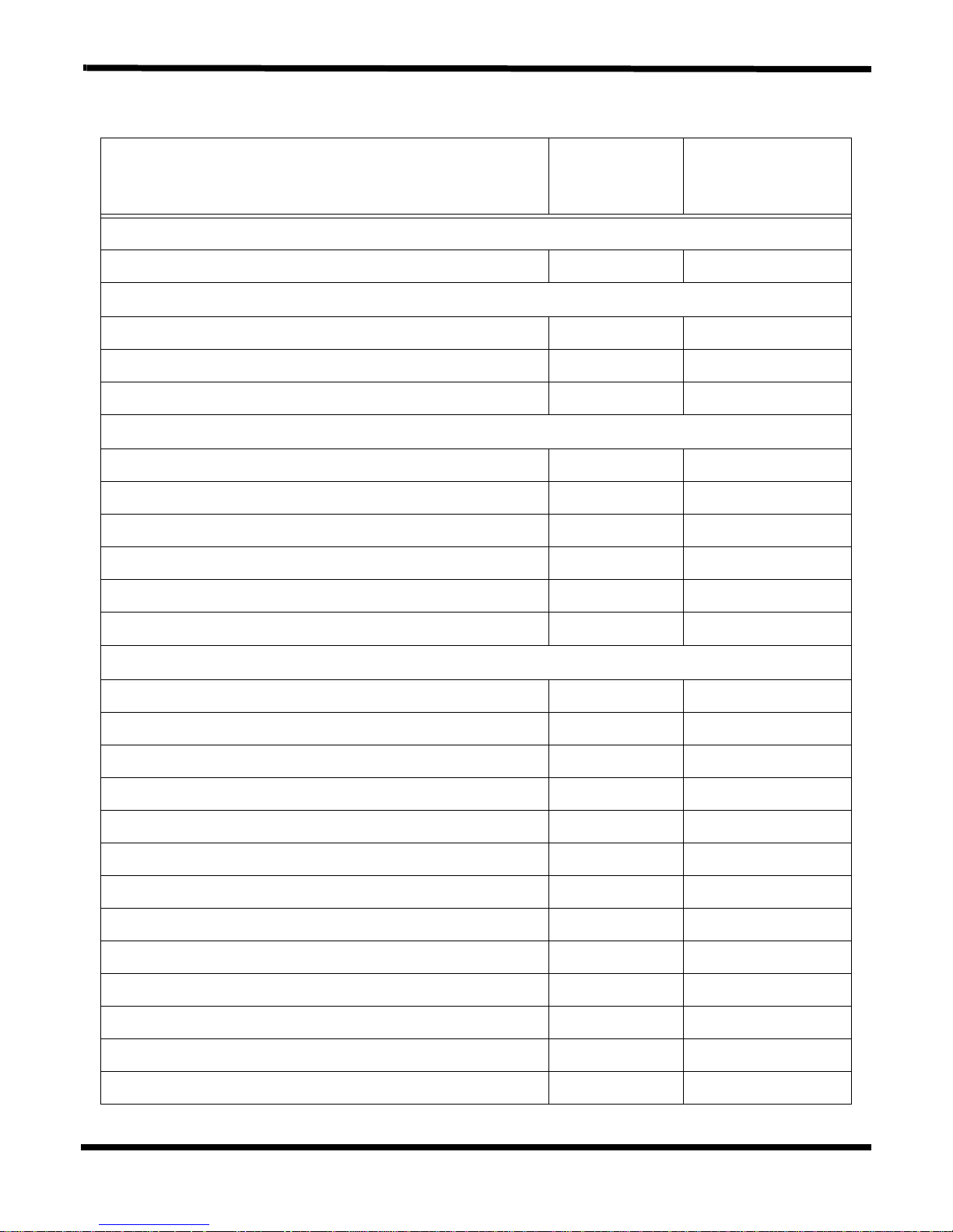
Table A-2 Base Assembly Field-Replaceable Units (FRUs)
Base Assembly FRU Description Assembly/
TI Part No.
Disassembly
Paragraph
Cables
CD-ROM Cable 6.5.8 9813523-0001
Peripherals
Microfloppy Drive (FDD) 6.5.8 9813513-0001
HDD, 810 MB 6.5.3 9813517-0001
CD-ROM Drive, 6X 6.5.8 9813486-0001
Covers, Doors, Buttons
Top Cover Assembly 6.5.10 9813511-0001
Memory Expansion Cover 6.5.5 9813510-0001
Left Hinge Cover 6.5.4 9813508-0001
Right Hinge Cover 6.5.4 9813509-0001
Hinge Cable Cover Ref 9813507-0001
HDD Cover 6.5.3 9813506-0001
Misc
Base Assembly 6.5.9 9813499-0001
Battery, Duracell, Ni-MH, SMB, (10.8V, 2800 mah) 6.5.1 9813495-0001
AC Power Adapter, 45W, ADP-45HB Ref 9813497-0001
Nameplate Label Ref
Fan with connector cable 6.5.11 9813538-0001
Inside Frame 6.5.14 9813522-0001
Heat Sink Assembly 6.5.6 9813519-0001
CPU IC (P54CSLM-120 MHz, 3.1V 6.5.7 9813526-0001
FDD/CD-ROM Latch 6.5.8 9813524-0001
Mouse Buttons 6.5.21 9813527-0001
Nameplate, Extensa 600 Ref 9813553-0001
Nameplate, Extensa 600CD Ref 9813553-0002
Nameplate, Extensa 605CD Ref 9813553-0003
Model 60x Maintenance Data A-7
Page 9

Table A-2 Base Assembly Field-Replaceable Units (FRUs)
Base Assembly FRU Description Assembly/
TI Part No.
Disassembly
Paragraph
PCMCIA Connector Module 6.5.20 9813549-0001
Left Speaker with cable Ref 9813535-0001
Cover-closed switch Ref 9813537-0001
A.4 Logic Diagrams
Logic diagrams for the Extensa 60x Series Motherboard PWB Assembly are provided in
Figure A-4.
A-8 Model 60x Maintenance Data
Page 10
Model 65x Maintenance Data
B.1 Introduction
This section contains model-dependent maintenance data for the Extensa Model 65x
Series Notebook Computers. For information common to all members of the Extensa
60x and 65x Series, refer to Sections 1 through 6 of this manual.
B.2 Model 65x Features Summary
The Extensa 65x Series Notebook Computers comes standard with either a 11.3-inch
or 12.1-inch Super VGA Display, 1.3 GB or larger Hard Drive and is powered by a 133
MHz Pentium processor. Refer to Section 1 for a more detailed description of Extensa
65x Series features.
B.3 Field-Replaceable Units (FRUs)
Note: For FRU removal/replacement procedures, refer to Section 6 of this
manual.
B
As shown in Figure B-1, all members of the Extensa 65x Series Notebook Computers
contain two major assemblies:
♦ System Base Assembly
♦ Cover-Display Assembly
Model 65x Maintenance Data B-1
Page 11
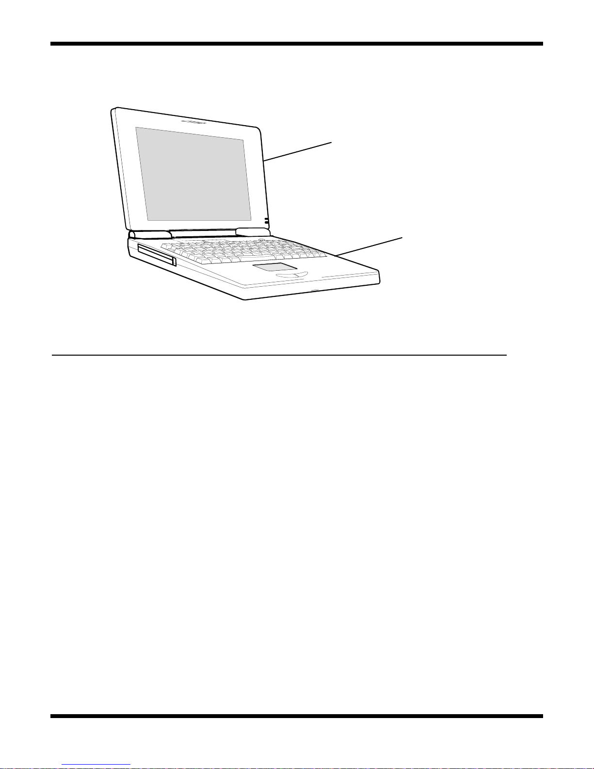
Figure B-1 Extensa 65x Series Assemblies
B.3.1 Cover-Display Assembly
The Cover-Display Assembly shown in Figure B-2, contains the LCD screen, DC-AC
Inverter Board Logic, DC-DC Inverter Board Logic, bezel LCD cover and various other
components as listed in Table B-1.
Display Assembly
Base Assembly
B-2 Model 65x Maintenance Data
Page 12

.
LCD Panel
DC-AC Inverter
Board Assembly
DC-DC Inverter
Board
Display Cable
Display Assembly
Shown with
Bezel Removed
Figure B-2 Display FRUs
Table B-1 Top Cover Assembly Field-Replaceable Units (FRUs)
FRU Description Assembly/
Disassembly
Paragraph
LCD Panel, 11.3", TFT 6.5.24 9813488-0001
LCD Panel, 12.1", DSTN 6.5.24 9813483-0001
Display Back Cover, 12.1" 6.5.19 9813480-0001
Display Bezel, 11.3" 6.5.22 9813482-0001
Display Bezel, 12.1" 6.5.22 9813547-0001
LCD Round Bumper Ref 9813550-0001
TFT DC-DC Inverter PWB Assembly 6.5.23 9813493-0001
Inverter Board PWB Assembly, Ext. 500/505/
510/515
6.5.23 9811361-0001
TI Part No.
ASTN/DSTN DC-DC Inverter PWB Assembly 6.5.23 9813531-0001
Model 65x Maintenance Data B-3
Page 13

Table B-1 Top Cover Assembly Field-Replaceable Units (FRUs)
FRU Description Assembly/
TI Part No.
Disassembly
Paragraph
Display Cable Assembly, 12.1" Display 6.5.9 9813548-0001
Display Cable Assembly, 11.3" Display 6.5.9 9813476-0001
Display Bezel, 11.3" 6.5.22 9813482-0001
Display Bezel, 12.1" 6.5.22 9813547-0001
LCD Screw Cover Right Ref 9813551-0001
LCD Screw Cover Left Ref 9813552-0001
Left Hinge, ASTN 10.4" Ref 9813520-0001
Right Hinge, DSTN, 12.1" Ref 9813521-0001
B-4 Model 65x Maintenance Data
Page 14

B.3.2 System Base Assembly
As shown in Figure B-3, the System Base Assembly houses a variety of field-replaceable
subassemblies and components. The various assemblies and reference paragraph
numbers containing removal/replacement procedures are listed in Table B-2.
Keyboard
Assembly
CD-ROM Drive Module
or FDD Module
Battery Pack
Touchpad
Assembly
HDD Assembly
(Underneath)
LED
Assembly
Fan
Assembly
Motherboard
Assembly
Power Supply
Board Assembly
FIR/Audio
Board
Battery
Board
Model 65x Maintenance Data B-5
Figure B-3 Base Assembly FRUs
Page 15

Table B-2 Base Assembly Field-Replaceable Units (FRUs)
Base Assembly FRU Description Assembly/
TI Part No.
Disassembly
Paragraph
PWB Assemblies
Motherboard Logic PWB Assembly 6.5.17 9813490-0001
FIR/Audio PWB Assembly 6.5.18 9813491-0001
LED PWB Assembly 6.5.12 9813492-0001
Power Supply PWB Assembly 6.5.16 9813534-0001
Battery Connector PWB W/Cable Ref 9813529-0001
KeyBoard Logic Transfer PWB Assembly Ref 9813532-0001
Touchpad Assembly 6.5.21 9813516-0001
Button Board Logic w/Cable Assembly Ref 9813501-0001
KeyBoard Logic Assemblies
KeyBoard Logic Assembly (U.S.) 6.5.4 9805758-0001
KeyBoard Logic Assembly (UK) 6.5.4 9805758-0002
KeyBoard Logic Assembly (German) 6.5.4 9805758-0003
KeyBoard Logic Assembly (French) 6.5.4 9805758-0004
KeyBoard Logic Assembly (Spanish) 6.5.4 9805758-0005
KeyBoard Logic Assembly (Swiss/German) 6.5.4 9805758-0006
KeyBoard Logic Assembly (Italian) 6.5.4 9805758-0007
KeyBoard Logic Assembly (Portuguese) 6.5.4 9805758-0008
KeyBoard Logic Assembly (Sweden) 6.5.4 9805758-0010
KeyBoard Logic Assembly (Danish) 6.5.4 9805758-0012
KeyBoard Logic Assembly (Norwegian) 6.5.4 9805758-0013
KeyBoard Logic Assembly (Finnish) 6.5.4 9805758-0014
KeyBoard Logic Assembly (Belgian) 6.5.4 9805758-0015
KeyBoard Logic Assembly (Chinese) 6.5.4 9805758-0019
KeyBoard Logic Assembly (Korean) 6.5.4 9805758-0020
KeyBoard Logic Assembly (Japanese) 6.5.4 9805758-0021
B-6 Model 65x Maintenance Data
Page 16

Table B-2 Base Assembly Field-Replaceable Units (FRUs)
Base Assembly FRU Description Assembly/
TI Part No.
Disassembly
Paragraph
Cables
CD-ROM Cable 6.5.8 9813523-0001
Peripherals
FDD Assy, 1.44 MB 6.5.8 9813484-0001
HDD, 1.44 GB 6.5.3 9813536-0001
CD-ROM Drive, 8X 6.5.8 9813543-0001
Covers, Doors, Buttons
Top Cover Assembly 6.5.11 9813481-0001
Memory Expansion Cover 6.5.5 9813510-0001
Left Hinge Cover Ref 9813508-0001
Right Hinge Cover Ref 9813509-0001
Hinge Cable Cover Ref 9813507-0001
HDD Cover 6.5.4 9813479-0001
Battery Door, 600 Series 6.5.1 9813576-0001
Misc
Base Assembly, 65x 6.5.10 9813477-0001
Battery, Duracell, Ni-MH, SMB, (10.8V, 2800 mah) 6.5.1 9813495-0001
AC Power Adapter, 45W, ADP-45HB Ref 9813497-0001
Fan with connector cable 6.5.11 9813538-0001
Inside Frame Assembly 6.5.15 9813487-0001
Heat Sink Assembly, 65x 6.5.7 9813475-0001
CPU IC (P54CSLM-133 MHz, 3.1V 6.5.8 9813530-0001
Mouse Buttons 6.5.21 9813527-0001
PCMCIA Connector Module 6.5.20 9813549-0001
Right Speaker with cable Ref 9813494-0001
Model 65x Maintenance Data B-7
Page 17

Table B-2 Base Assembly Field-Replaceable Units (FRUs)
Base Assembly FRU Description Assembly/
TI Part No.
Disassembly
Paragraph
Left Speaker with cable Ref 9813535-0001
Cover-closed switch Ref 9813537-0001
Cover, FIR/Audio Board 6.5.18 9813504-0001
Microphone W/Cable Ref 9813489-0001
B.4 65x Logic Diagrams
The remainder of this section contains logic diagrams for the Extensa Model 65x Series.
Figure B-4 (36 sheets) contains the logic diagrams for the main board; FigureB-5
contains the logic diagrams for the VGA Board.
B-8 Model 65x Maintenance Data
 Loading...